

Page 1

Pub. 42003-230A
GAI-TRONICS® CORPORATION
A HUBBELL COMPANY
Keypad Seal Kit
for 246C, 256C, 246-001 & 256-001 Phones
Model 12613-001
Confidentiality Notice
This manual is provided solely as an operational, installation, and maintenance guide and contains
sensitive business and technical information that is confidential and proprietary to GAI-Tronics.
GAI-Tronics retains all intellectual property and other rights in or to the information contained herein,
and such information may only be used in connection with the operation of your GAI-Tronics product or
system. This manual may not be disclosed in any form, in whole or in part, directly or indirectly, to any
third party.
General Information
The Model 12613-001 Keypad Seal Door Kit is for use on the GAI-Tronics Model 246C, 256C, 246-001
and 256-001 Industrial Phones. This kit includes the following components:
Item Qty. Description
A 1 Keypad mounting panel assembly
B 8
C 1 Keypad seal
D 1 Keypad spacer plate
E 2 .062-inch flat nylon washer
PPHTF screws #4 × ¼-inch
Installation
Unpack the material and compare the included parts to the list above to ensure that all parts are present.
N
OTE: Large and small tip Phillips head screw drivers and ¼-inch nut driver are required for installation
of this kit.
Disassembly
1. Unscrew front panel of phone from enclosure/back box and carefully disconnect the field wiring.
Please make note of all field wiring connections.
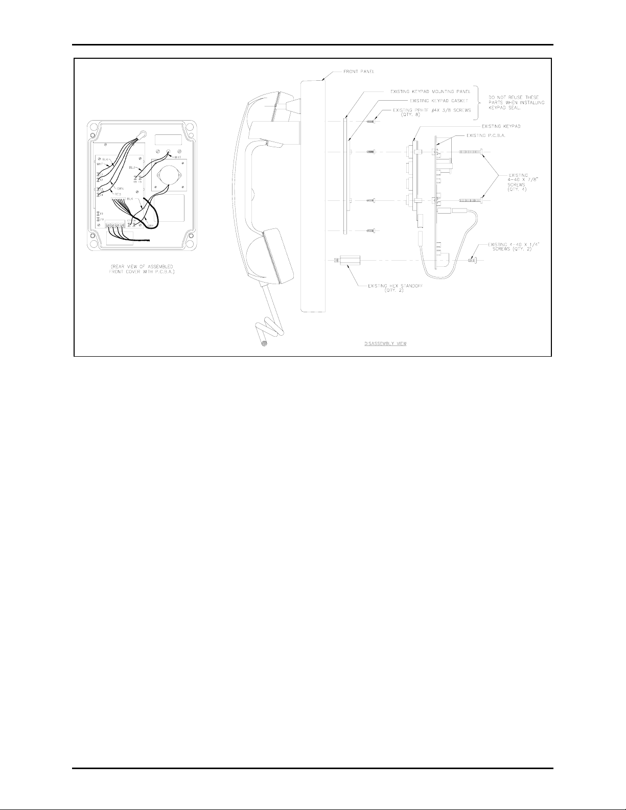
2. See Figure 1. The printed circuit board assembly (PCBA) is mounted with six screws. Four screws
mount to the keypad mounting panel below and two mount to standoffs on the phone front panel.
Remove the two 4-40 × ¼-inch screws from the hex standoffs and save for reassembly later.
Unscrew the other four screws about ¼ inch or until they disengage from the keypad mounting panel
below. (These screws will also be reused when re-assembly later.)
GAI-Tronics Corporation 400 E. Wyomissing Ave. Mohnton, PA 19540 USA
610-777-1374 800-492-1212 Fax: 610-796-5954
V
ISIT WWW.GAI-TRONICS.COM FOR PRODUCT LITERATURE AND MANUALS
Page 2
Pub. 42003-230A
ODEL 12613-001 KEYPAD SEAL KIT Page: 2 of 3
M
Figure 1. Disassembly View
3. Carefully flip PCBA up and away from obstructing access to the keypad and keypad mounting panel.
4. Lift keypad off the keypad mounting panel. There may be some resistance due to the keypad sticking
to the gasket on the keypad mounting panel.
5. Remove the eight screws holding the keypad mounting panel to the phone front panel. These screws
will NOT be reused in reassembling the keypad assembly.
6. The keypad mounting panel may be stuck to another gasket on the phone front panel and may require
some force to lift it up and off. Once dislodged from the phone, the front panel it will NOT be
reused.
Reassembly
1. See Figure 2. Install supplied keypad mounting panel (A) with eight supplied PPHTF #4 × ¼-inch
screws (B) as shown in Figure 2. Make sure that screws are uniformly tightened in a crisscross
pattern to ensure even pressure with the phone front panel gasket.
2. Press keypad seal (C) into the keypad mounting panel grid (A). Make sure that keypad seal numbers
are in the correct orientation with the phone front panel. Verify that each key position of the seal is
seated completely in each grid square and around the standoffs on the keypad mounting plate.
3. Place keypad spacer plate (D) over the keypad seal and standoffs on the keypad mounting panel.
4. Unscrew the two ¼-inch hex standoffs mounted to the phone front panel. Place one nylon washer (E)
under each standoff and screw the standoffs back into position on the phone front panel.
f:\standard ioms - current release\42003 kit manuals\42003-230a.doc
04/10
Page 3

Pub. 42003-230A
ODEL 12613-001 KEYPAD SEAL KIT Page: 3 of 3
M
5. Place keypad onto keypad spacer plate.
6. Carefully flip PCBA back over and into place lining up the four long mounting screws through the
mounting holes in the keypad and into the keypad mounting bracket (A). Make sure all four screws
are engaged before tightening. Once they are all engaged tighten in a crisscross pattern to ensure
even pressure with the keypad spacer plate (D) and keypad seal (C).
7. Install the two 4-40 × ¼-inch screws from step 2 of the disassembly procedure.
8. Hold phone panel in upright position and press each key on keypad to verify that each button has
movement.
9. Check for any loose wire connections on the PCBA.
10. Connect field wiring from step 1 of disassembly procedure and screw the front panel to
enclosure/back box.
Figure 2. Reassembly View
f:\standard ioms - current release\42003 kit manuals\42003-230a.doc
04/10
Page 4

Warranty
Equipment. GAI-Tronics warrants for a period of one (1) year from the date of shipment, that any
GAI-Tronics equipment supplied hereunder shall be free of defects in material and workmanship, shall
comply with the then-current product specifications and product literature, and if applicable, shall be fit
for the purpose specified in the agreed-upon quotation or proposal document. If (a) Seller’s goods prove
to be defective in workmanship and/or material under normal and proper usage, or unfit for the purpose
specified and agreed upon, and (b) Buyer’s claim is made within the warranty period set forth above,
Buyer may return such goods to GAI-Tronics’ nearest depot repair facility, freight prepaid, at which time
they will be repaired or replaced, at Seller’s option, without charge to Buyer. Repair or replacement shall
be Buyer’s sole and exclusive remedy. The warranty period on any repaired or replacement equipment
shall be the greater of the ninety (90) day repair warranty or one (1) year from the date the original
equipment was shipped. In no event shall GAI-Tronics warranty obligations with respect to equipment
exceed 100% of the total cost of the equipment supplied hereunder. Buyer may also be entitled to the
manufacturer’s warranty on any third-party goods supplied by GAI-Tronics hereunder. The applicability
of any such third-party warranty will be determined by GAI-Tronics.
Services. Any services GAI-Tronics provides hereunder, whether directly or through subcontractors,
shall be performed in accordance with the standard of care with which such services are normally
provided in the industry. If the services fail to meet the applicable industry standard, GAI-Tronics will
re-perform such services at no cost to buyer to correct said deficiency to Company's satisfaction provided
any and all issues are identified prior to the demobilization of the Contractor’s personnel from the work
site. Re-performance of services shall be Buyer’s sole and exclusive remedy, and in no event shall GAITronics warranty obligations with respect to services exceed 100% of the total cost of the services
provided hereunder.
Warranty Periods. Every claim by Buyer alleging a defect in the goods and/or services provided
hereunder shall be deemed waived unless such claim is made in writing within the applicable warranty
periods as set forth above. Provided, however, that if the defect complained of is latent and not
discoverable within the above warranty periods, every claim arising on account of such latent defect shall
be deemed waived unless it is made in writing within a reasonable time after such latent defect is or
should have been discovered by Buyer.
Limitations / Exclusions. The warranties herein shall not apply to, and GAI-Tronics shall not be
responsible for, any damage to the goods or failure of the services supplied hereunder, to the extent
caused by Buyer’s neglect, failure to follow operational and maintenance procedures provided with the
equipment, or the use of technicians not specifically authorized by GAI-Tronics to maintain or service the
equipment. THE WARRANTIES AND REMEDIES CONTAINED HEREIN ARE IN LIEU OF AND
EXCLUDE ALL OTHER WARRANTIES AND REMEDIES, WHETHER EXPRESS OR IMPLIED BY
OPERATION OF LAW OR OTHERWISE, INCLUDING ANY WARRANTIES OF
MERCHANTABILITY OR FITNESS FOR A PARTICULAR PURPOSE.
Return Policy
If the equipment requires service, contact your Regional Service Center for a return authorization number
(RA#). Equipment should be shipped prepaid to GAI-Tronics with a return authorization number and a
purchase order number. If the equipment is under warranty, repairs or a replacement will be made in
accordance with the warranty policy set forth above. Please include a written explanation of all defects to
assist our technicians in their troubleshooting efforts.
Call 800-492-1212 (inside the USA) or 610-777-1374 (outside the USA) for help identifying the
Regional Service Center closest to you.
(Rev. 10/06)
 Loading...