

Page 1

Pub. 42003-174
GAI-TRONICS® CORPORATION
A HUBBELL COMPANY
Party-Li ne Selector Knob Replacement Kit
MODEL 12607-002
Confidentiality Notice
This manual is pr ovided s olely as a n op erat ional, installation, and maintenance guide and contains sens itive
bus ines s and t echnic al infor ma tion tha t is confident ial and prop rieta ry to GAI - Tr onic s. GAI- Tr onic s retains
all intellectual prop erty a nd other r ights in or to the information contained herein, and s uch infor ma tion may
only be used in connection with t he op erat ion of your GAI-T ronics produ c t or s ystem. This manu al may not
be disclos ed in any form, in whole or in pa rt, direct ly or indirectly, t o any third party.
General Information
The Model 12607-002 Replacement Kit is provided to replace the party line selector knob on the
GAI-Tronics Model 7115-102, 7165-102, and 7265-101 Page/Party
following components :
®
su bsets. T h i s kit incl udes the
Qty Description
1 Knob
1 Knob Cap
1 Selector Switch Assembly (includes P CBA)
Installation
Model 7115-102 Desk-edge and 7165-102 Flush-Mount Subsets
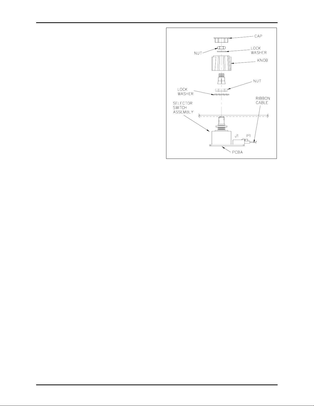
Refer to Figure 1.
1. Remove the four screws securing the side cover of the Model 7115-102 or the rear cover of the Model
7165-102. Save for re-assembly.
2. Disconnect the ribbon cable fr om the s elector s wit c h ass embly PCBA.
3. Pop the cap out of the top of the knob and discard the cap.
4. Remove the nut and the lock washer from the knob and save for re-assembly. D i scard the knob.
Note the p ointer position when r emoving a nd ens ure that t he p ointer on new knob is reinst alled in the
same position.
5. Remove the remaining nu t and lock washer and remove the old selector s wit ch assembly. S ave the nut
and lock washer for re-assembly.
GAI-Tronics Corporation P.O. Box 1060, Reading, PA 19607-1060 USA
610-777-1374 800-492-1212 Fax : 610-796-5954
ISIT WWW.GAI-TRONICS.COM FOR PRODUCT LITERATURE AND MANUALS
V
Page 2
Pub. 42003-174
M
ODEL 12607-002 PARTY-LINE SELECTOR REPLACEMENT KIT Page: 2 of 2
6. Insert the new selector switch assembly through
the panel.
7. Insert a lock washer over the switch shaft and
secure with a nut.
8. Pla c e the new knob over the selector switch
assembly.
9. Adjust the knob point er posi tion.
10. Tighten the nut against the lock washer in the
knob.
11. Insert the new cap into the top of the knob .
12. Reconnec t the ribbon ca ble to the s elect or switc h
assembly PCBA.
13. R epla ce the four cover screws.
Figure 1. Knob Assembly View
Model 7265-101 Desktop Subset
Refer to Figure 1.
1. Remove the top c hass i s from t he b ase of the unit b y removing the four screws from the bottom of the
subset. Save for re-assembly.
2. Disconnect the ribbon cable fr om the s elector s wit c h ass embly PCBA.
3. Pop the cap out of the top of the knob and discard the cap.
4. Remove the nut, lock wa sher, and knob. Note p ointer position when removing and ensure tha t the
pointer is reinstalled in the same position.
5. Remove the remaining nu t and t he lock washer and remove the old selector s wit c h ass embly. Save the
nut and lock washer for re- ass embly.
6. Inser t the new selector switc h ass embly t hrough t he front p anel.
7. Insert the lock washer over the selector switch assembly shaft and secure with the nut.
8. Pla c e the new knob over the s elector s witch as sembly.
9. Adjust the knob point er posi tion.
10. Tighten the nu t against the lock was her in the knob.
11. Insert the new cap into the top of the knob .
12. Reconnect the r ibbon ca ble to the select or swit c h assembly PCBA.
13. Secure the chassis to the base using the four screws.
\\s_eng\gtc proddoc s \ s tandard ioms - current release\ 42003 k it m anuals \42003-174.doc
5/99
Page 3

Warranty
Equipment. GAI-Tronics warrants for a period of one (1) year from the date of shipment, that any
GAI-Tronics equipment supplied hereunder shall be free of defects in material and workmanship, shall
comply with the then-current product specifications and product literature, and if applicable, shall be fit
for the purpose specified in the agreed-upon quotation or proposal document. If (a) Seller’s goods prove
to be defective in workmanship and/or material under normal and proper usage, or unfit for the purpose
specified and agreed upon, and (b) Buyer’s claim is made within the warranty period set forth above,
Buyer may return such goods to GAI-Tronics’ nearest depot repair facility, freight prepaid, at which time
they will be repaired or replaced, at Seller’s option, without charge to Buyer. Repair or replacement shall
be Buyer’s sole and exclusive remedy. The warranty period on any repaired or replacement equipment
shall be the greater of the ninety (90) day repair warranty or one (1) year from the date the original
equipment was shipped. In no event shall GAI-Tronics warranty obligations with respect to equipment
exceed 100% of the total cost of the equipment supplied hereunder. Buyer may also be entitled to the
manufacturer’s warranty on any third-party goods supplied by GAI-Tronics hereunder. The applicability
of any such third-party warranty will be determined by GAI-Tronics.
Services. Any services GAI-Tronics provides hereunder, whether directly or through subcontractors,
shall be performed in accordance with the standard of care with which such services are normally
provided in the industry. If the services fail to meet the applicable industry standard, GAI-Tronics will
re-perform such services at no cost to buyer to correct said deficiency to Company's satisfaction provided
any and all issues are identified prior to the demobilization of the Contractor’s personnel from the work
site. Re-performance of services shall be Buyer’s sole and exclusive remedy, and in no event shall GAITronics warranty obligations with respect to services exceed 100% of the total cost of the services
provided hereunder.
Warranty Periods. Every claim by Buyer alleging a defect in the goods and/or services provided
hereunder shall be deemed waived unless such claim is made in writing within the applicable warranty
periods as set forth above. Provided, however, that if the defect complained of is latent and not
discoverable within the above warranty periods, every claim arising on account of such latent defect shall
be deemed waived unless it is made in writing within a reasonable time after such latent defect is or
should have been discovered by Buyer.
Limitations / Exclusions. The warranties herein shall not apply to, and GAI-Tronics shall not be
responsible for, any damage to the goods or failure of the services supplied hereunder, to the extent
caused by Buyer’s neglect, failure to follow operational and maintenance procedures provided with the
equipment, or the use of technicians not specifically authorized by GAI-Tronics to maintain or service the
equipment. THE WARRANTIES AND REMEDIES CONTAINED HEREIN ARE IN LIEU OF AND
EXCLUDE ALL OTHER WARRANTIES AND REMEDIES, WHETHER EXPRESS OR IMPLIED BY
OPERATION OF LAW OR OTHERWISE, INCLUDING ANY WARRANTIES OF
MERCHANTABILITY OR FITNESS FOR A PARTICULAR PURPOSE.
Return Policy
If the equipment requires service, contact your Regional Service Center for a return authorization number
(RA#). Equipment should be shipped prepaid to GAI-Tronics with a return authorization number and a
purchase order number. If the equipment is under warranty, repairs or a replacement will be made in
accordance with the warranty policy set forth above. Please include a written explanation of all defects to
assist our technicians in their troubleshooting efforts.
Call 800-492-1212 (inside the USA) or 610-777-1374 (outside the USA) for help identifying the
Regional Service Center closest to you.
(Rev. 10/06)
 Loading...