

Page 1

Pub. 42003-117B
GAI-TRONICS® CORPORATION
A HUBBELL COMPANY
Multi-Party Switch Kits and Harness
Assemblies
PRODUCT INFORMATION UPDATE
Confidentiality Notice
This manual is pr ovided s olely as a n op erat ional, installation, and maintenance guide and contains sens itive
bus ines s and t echnic al infor ma tion which is conf idential and propriet ary to GAI-Tronics. GAI - Tronic s
retains a ll intellectual pr operty and other rights in or to t he inf ormation c ontained herein, and s uch
informa tion may only be used in connection wit h the operation of you r GAI- Tronic s pr oduct or system.
This ma nual may not be disclosed in any form, in whole or in p art, dir ec tly or indirectly, to any t hird pa rty.
General Information
The infor ma tion in this publication a pplies to the following kits:
Kit Number Description
12607-001 5-Party Line Switch Kit for Indoor Sta tions
12609-001 Harness Assembly/Switch for 5-Party Line Weatherproof Stations
12609-002 Harness Assembly/Switch for 5-Party Line Indoor S tat ions
Application
5-Par ty Syst ems
In response to customer f eedback, GAI-T ronics has improved the 5-P arty Line Switch. The switch has
been improved to withstand twice a s much pressure as the old switch. As a result of this c hange, the
var i able “stop” was removed. We hope that t his change meets with your approval.
2, 3, and 4-Party Systems
GAI-Tronics has made available a resistor kit, Model 12509-002, designed for installation in 2, 3, and
4-part y systems. Inst allat ion of this kit will eliminate the need for a “st op ” on the party-line select or
switch. When insta lled, this kit will also p revent feedback to the hands et if the party-line selector switc h is
ina d v ert en tly turned t o an unused par ty lin e.
GAI-Tronics Corporation P.O. Box 1060, Reading, PA 19607-1060 USA
610-777-1374 800-492-1212 Fax : 610-796-5954
ISIT WWW.GAI-TRONICS.COM FOR PRODUCT LITERATURE AND MANUALS
V
Page 2
Pub. 42003-117B
M
ULTI-PARTY SWITCH AND HARNESS REPLACEMENT KIT Page: 2 of 2
Installation
Model 12607-001 5-Party Line Switch Kit for Indoor Stations
1
1. Remove the knob a nd the old switch. Use a
wrench t o loosen the 2 s et screws in the s elector knob . One sc rew
is to the right of the party-line indicator; the ot her screw is in the
end of the knob. After loosening the screws, lift the knob off, and
set it and the screws aside. Save t he knob .
2. Write down where all t he wires and jumpers are connected.
3. Remove all the wir es and jumper s from the old s witch.
Note: Keep the wires as long as pos sible.
/16
-inch (#21) Allen
4. J-hook a ll the connections before soldering on the new switc h. This
proc es s will ensur e a good mechanica l c onnection. See Figur e 1 .
Knob Installation
Suggested Tools
1
/16
•
• Adjustable Torque Driver
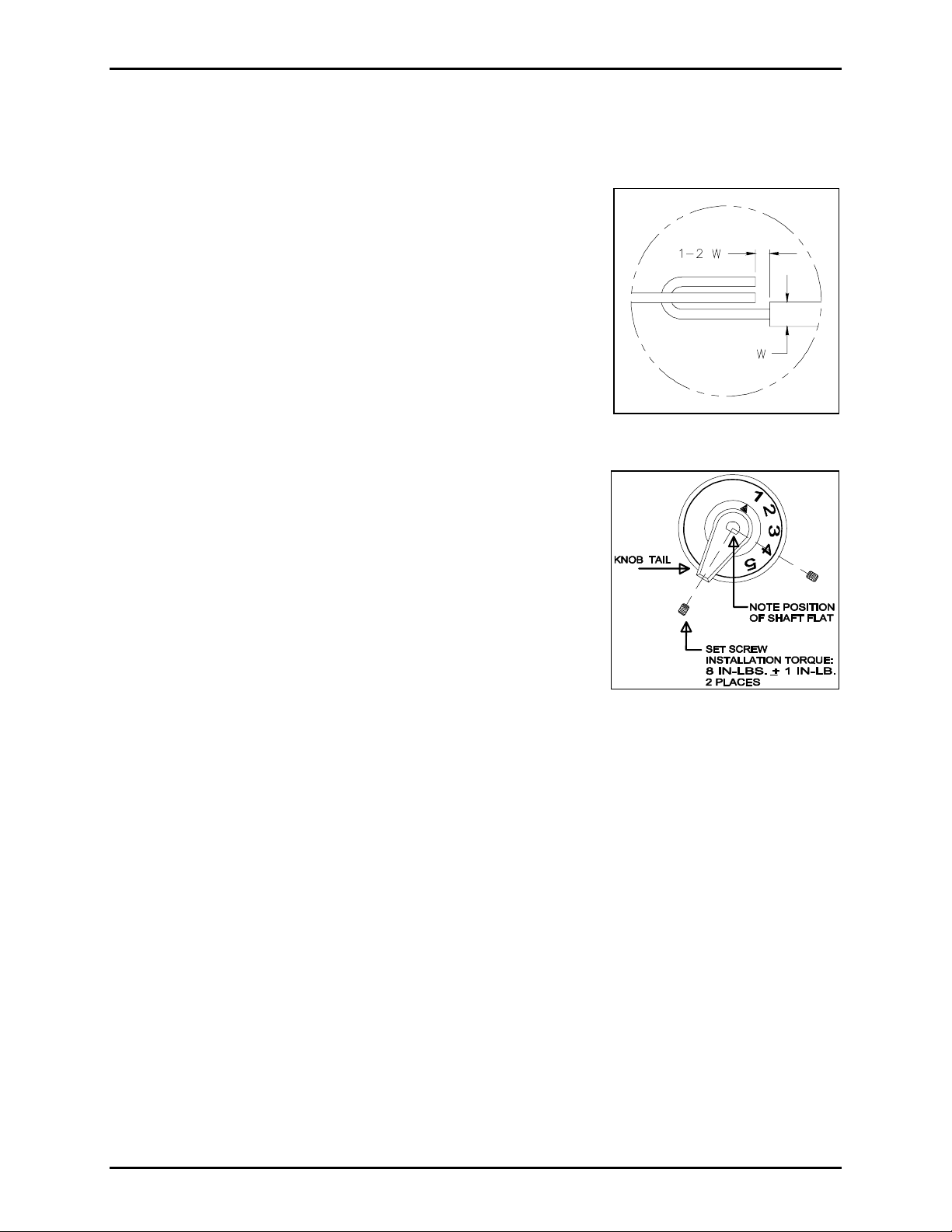
1. Set adjust able torque driver to 8 inc h- pounds.
2. Tighten the set screw at the tail end of the switch. Note the position
3. Tighten the remaining set sc rew.
-inch (#21) Allen Wrench
of the shaft f lat with respect to the tail of the knob. See Figure 2.
Figure 1. Proper J- Hook
Figure 2. Knob Installation
\\s_eng\gtc proddoc s \ s tandard ioms - current release\ 42003 k it m anuals \42003-117b.doc
6/98
Page 3

Warranty
Equipment. GAI-Tronics warrants for a period of one (1) year from the date of shipment, that any
GAI-Tronics equipment supplied hereunder shall be free of defects in material and workmanship, shall
comply with the then-current product specifications and product literature, and if applicable, shall be fit
for the purpose specified in the agreed-upon quotation or proposal document. If (a) Seller’s goods prove
to be defective in workmanship and/or material under normal and proper usage, or unfit for the purpose
specified and agreed upon, and (b) Buyer’s claim is made within the warranty period set forth above,
Buyer may return such goods to GAI-Tronics’ nearest depot repair facility, freight prepaid, at which time
they will be repaired or replaced, at Seller’s option, without charge to Buyer. Repair or replacement shall
be Buyer’s sole and exclusive remedy. The warranty period on any repaired or replacement equipment
shall be the greater of the ninety (90) day repair warranty or one (1) year from the date the original
equipment was shipped. In no event shall GAI-Tronics warranty obligations with respect to equipment
exceed 100% of the total cost of the equipment supplied hereunder. Buyer may also be entitled to the
manufacturer’s warranty on any third-party goods supplied by GAI-Tronics hereunder. The applicability
of any such third-party warranty will be determined by GAI-Tronics.
Services. Any services GAI-Tronics provides hereunder, whether directly or through subcontractors,
shall be performed in accordance with the standard of care with which such services are normally
provided in the industry. If the services fail to meet the applicable industry standard, GAI-Tronics will
re-perform such services at no cost to buyer to correct said deficiency to Company's satisfaction provided
any and all issues are identified prior to the demobilization of the Contractor’s personnel from the work
site. Re-performance of services shall be Buyer’s sole and exclusive remedy, and in no event shall GAITronics warranty obligations with respect to services exceed 100% of the total cost of the services
provided hereunder.
Warranty Periods. Every claim by Buyer alleging a defect in the goods and/or services provided
hereunder shall be deemed waived unless such claim is made in writing within the applicable warranty
periods as set forth above. Provided, however, that if the defect complained of is latent and not
discoverable within the above warranty periods, every claim arising on account of such latent defect shall
be deemed waived unless it is made in writing within a reasonable time after such latent defect is or
should have been discovered by Buyer.
Limitations / Exclusions. The warranties herein shall not apply to, and GAI-Tronics shall not be
responsible for, any damage to the goods or failure of the services supplied hereunder, to the extent
caused by Buyer’s neglect, failure to follow operational and maintenance procedures provided with the
equipment, or the use of technicians not specifically authorized by GAI-Tronics to maintain or service the
equipment. THE WARRANTIES AND REMEDIES CONTAINED HEREIN ARE IN LIEU OF AND
EXCLUDE ALL OTHER WARRANTIES AND REMEDIES, WHETHER EXPRESS OR IMPLIED BY
OPERATION OF LAW OR OTHERWISE, INCLUDING ANY WARRANTIES OF
MERCHANTABILITY OR FITNESS FOR A PARTICULAR PURPOSE.
Return Policy
If the equipment requires service, contact your Regional Service Center for a return authorization number
(RA#). Equipment should be shipped prepaid to GAI-Tronics with a return authorization number and a
purchase order number. If the equipment is under warranty, repairs or a replacement will be made in
accordance with the warranty policy set forth above. Please include a written explanation of all defects to
assist our technicians in their troubleshooting efforts.
Call 800-492-1212 (inside the USA) or 610-777-1374 (outside the USA) for help identifying the
Regional Service Center closest to you.
(Rev. 10/06)
 Loading...