

Page 1
Pub. 42004-433C
GAI-TRONICS® CORPORATION
A HUBBELL COMPANY
Model 12600-002 and 12600-40x
Line Current Boost Cir cuit Assemblies
Confidential ity Notice
This manual is provided solely as an operational, installation, and maintenance guide and contains
sensitive business and technical information that is confidential and proprietary to GAI-Tronics.
GAI-Tronics retains all intellectual property and other rights in or to the information contained herein,
and such information may only be used in connection with the operation of your GAI-Tronics product or
system. This manual may not be disclosed in any form, in whole or in part, directly or indirectly, to any
third party.
General Information
This manual covers the following models of the GAI-Tronics Line Current Boost Circuit Assemblies:
Model Description
12600-002 Single Channel Line Current Boost Circuit
12600-401 4-Channel, DC-powered Line Current Boost Circuit
12600-402 8-Channel, DC-powered Line Current Boost Circuit
12600-403 4-Channel, AC-powered Line Current Boost Circuit
12600-404 8-Channel, AC-powered Line Current Boost Circuit
Telephone and PBX lines typically provide 20–35 mA or less line current to analog telephone
instruments. Several devices, including GAI-Tronics’ line of RED ALERT
require additional line current to drive speakers, power optical coupling devices, and electronic devices
such as microprocessors. The additional line current provided by the LCBC provides sufficient line
current for a substantial increase in audio power to
the emergency telephone speaker.
The GAI-Tronics Line Current
Boost Circuit (LCBC)
Assemblies are designed to
augment available line current
to an analog 2-wire bridged
ringing telephone line. They are
designed specifically to provide
an additional 30 mA line current
to a GAI-Tronics line-powered
emergency telephone.
®
emergency telephones,
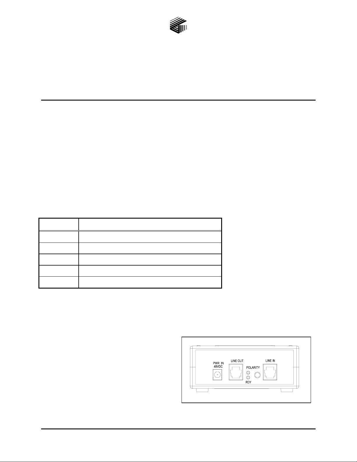
Operation
The LCBC is designed to be installed anywhere
along the telephone line, preferably at a main or
intermediate distribution location. A CMOS
differential amplifier and two threshold compactors
are used to monitor the dc voltage across the phone
line (tip and ring).
Figure 1. Model 12600-002
GAI-Tronics Corporation 400 E. Wyomissing Ave. Mohnton, PA 19540 USA
610-777-1374 800-492-1212 Fax: 610-796-5954
V
ISIT WWW.GAI-TRONICS.COM FOR PRODUCT LITERATURE AND MANUALS
Page 2
Pub. 42004-433C
Model 12600-002 and 12600-40x Line Current Boost Circuit Assemblies Page: 2 of 5
When the dc voltage between tip and ring falls below 15 V dc, indicating an off-hook condition on the
line, the LCBC automatically adds 30 mA current to the available line current. If the PBX provides 20
mA line current, the LCBC adds an additional line current of 30 mA for a total of 50 mA available to
drive speakers and other devices.
When the device connected to the line is placed on-hook (dc line voltage greater than 20 V), the LCBC
automatically disconnects the 30 mA supplemental line current. The LCBC is transparent to incoming
ring signals allowing operation on a 2-wire bridged ringing configuration.
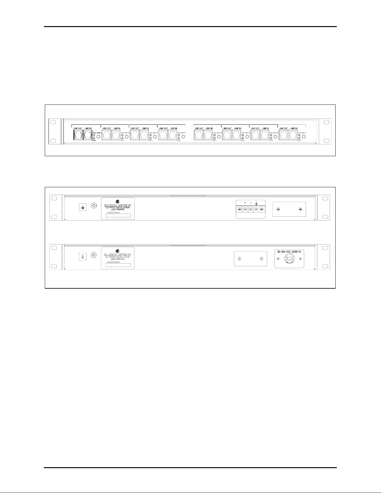
CHANNEL 1 CHANNEL 2 CHANNEL 3 CHANNEL 4 CHANNEL 5 CHANNEL 6 CHANNEL 7 CHANNEL 8
Figure 2. Front Views of Model 12600-402/404 8-Channel LCBC Assemblies
OTE: Model 12600-401/403 4-Channel LCBC Assemblies contain a blank panel on the right side.
N
48 VDC +/-20%
Figure 3. Rear Views of Models 12600-401/402 DC-Powered (top) and Models 12600-403/404
AC-Powered LCBC (bottom) Assemblies
P ABX Interface Requirements
Minimum loop current: 8 mA dc (LCBC disconnected)
Maximum recommended loop current: 40 mA dc (LCBC disconnected)
Ringer requirements: Type B ringer
f:\standard ioms - current release\42004 instr. manuals\42004-433c.doc
07/11
Page 3

Pub. 42004-433C
Model 12600-002 and 12600-40x Line Current Boost Circuit Assemblies Page: 3 of 5
Installation
Mounting
The12600-40x LCBC units can be placed on a table or desk, or can be mounted in a standard EIA 19-inch
electronic equipment rack, requiring 1U (1.75 inches) of vertical space.
If the LCBC is to be placed on a table or desk, install the four stabilizing feet.
For rack-mounting, install the mounting brackets using the eight 8-32 × 3/8-inch screws provided. Mount
the LCBC into the rack using the four 10-32 × ¾-inch screws provided.
Figure 4. Mounting Details
f:\standard ioms - current release\42004 instr. manuals\42004-433c.doc
07/11
Page 4

Pub. 42004-433C
Model 12600-002 and 12600-40x Line Current Boost Circuit Assemblies Page: 4 of 5
Wiring
CAUTION
Operation with line currents above 70 mA dc (includes LCBC 30 mA plus 40 mA line current) may
damage some telephone instruments. Line current can be measured by connecting a dc ammeter
between the tip and ring wires (red and green) from the telephone line. Polarity of the current is
unimportant.
Install a UL lightning arrestor on the L
exposed to lightning strikes. The lightning arrestor must be installed as close to the phone as possible to
maximize the protection. It must not be installed within the enclosure supplied with the phone. Please
consult our Service Center at 800-492-1212 for further information.
Install the Line Current Boost Circuit Assembly as follows.
1. Connect incoming PBX line(s) to LINE
2. Connect the telephone instrument(s) to LINE
3. Connect the power source.
4. Place the telephone instrument(s) on-hook.
5. If the green POLARITY light is on, the polarity for that line or channel is correct.
6. If the POLARITY light is off, press the associated POLARITY button. The POLARITY light should
turn on.
The dc line current (LCBC disconnected) should be less than 40 mA dc.
INE IN and LINE OUT phone cable if they are at risk of being
IN connection(s).
OUT connection(s).
7. When the green POLARITY light and the blue READY light are on, the telephone instrument is
operational.
8. When the telephone instrument is taken off-hook the blue READY light goes off but the green
POLARITY indicator remains on.
Operation
After installation, no direct user interface is required for the operation of the Line Current Boost Circuit
Assembly.
Maintenance
Troubles hooting
Problem Solution
No LED illuminated. Check power supply.
Green LED will not illuminate. Check phone line for tip-ring voltage.
f:\standard ioms - current release\42004 instr. manuals\42004-433c.doc
07/11
Page 5

Pub. 42004-433C
Model 12600-002 and 12600-40x Line Current Boost Circuit Assemblies Page: 5 of 5
Specification s
Model 12600-002
Power supply............................................................................................. 48 V dc @ 250 mA (unregulated)
Input voltage to plug-in power supply....................................................................120 V ac +
Input power to plug-in power supply......................Off-hook: 6.0 W maximum; On-hook 4.0 W maximum
Dimensions ....................................................................4.50 × 3.00 × 2.00 inches (114.3 × 76.2 × 50.8mm)
Weight..................................................................................................................................................0.5 lbs.
Models 12600-401 and 402
Input voltage............................................................................................................................48 V dc +
Dimensions (without mounting brackets).................17.00 × 9.00 × 1.75 inches (431.8 × 228.6 × 44.4 mm)
With brackets........................................19.00 × 10.00 × 1.75 inches (482.6 × 254.0 × 44 mm)
Weight................................................................................................................................ 8.5 lbs. maximum
Models 12600-403 and 404
Input voltage..........................................................................................................85–264 V ac @ 50/60 Hz
Dimensions (without mounting brackets).................17.00 × 9.00 × 1.75 inches (431.8 × 228.6 × 44.4 mm)
With brackets........................................19.00 × 10.00 × 1.75 inches (482.6 × 254.0 × 44 mm)
Weight................................................................................................................................ 8.5 lbs. maximum
Environmental
Operating temperature............................................................................................................40º C to +70ºC
Supplemental line current...................................................................................................30 mA dc +
10% @ 60 Hz
20%
5 mA
PABX interface requirements:
Minimum on-hook tip/ring voltage.................................................................20 V dc (LCBC disconnected)
Minimum loop current...................................................................................8 mA dc (LCBC disconnected)
Maximum recommended loop current.........................................................40 mA dc (LCBC disconnected)
Optional ringer requirements....................................................................................................Type B ringer
N
OTES:
The supplemental line current has a negative temperature coefficient promoting temperature stability for
both the LCBC and the telephone instrument connected to the LCBC.
Transient protection.....................Meets the requirements of FCC Part 68 Type A & B transient protection
f:\standard ioms - current release\42004 instr. manuals\42004-433c.doc
07/11
Page 6

Warranty
Equipment. GAI-Tronics warrants for a period of one (1) year from the date of shipment, that any
GAI-Tronics equipment supplied hereunder shall be free of defects in material and workmanship, shall
comply with the then-current product specifications and product literature, and if applicable, shall be fit
for the purpose specified in the agreed-upon quotation or proposal document. If (a) Seller’s goods prove
to be defective in workmanship and/or material under normal and proper usage, or unfit for the purpose
specified and agreed upon, and (b) Buyer’s claim is made within the warranty period set forth above,
Buyer may return such goods to GAI-Tronics’ nearest depot repair facility, freight prepaid, at which time
they will be repaired or replaced, at Seller’s option, without charge to Buyer. Repair or replacement shall
be Buyer’s sole and exclusive remedy. The warranty period on any repaired or replacement equipment
shall be the greater of the ninety (90) day repair warranty or one (1) year from the date the original
equipment was shipped. In no event shall GAI-Tronics warranty obligations with respect to equipment
exceed 100% of the total cost of the equipment supplied hereunder. Buyer may also be entitled to the
manufacturer’s warranty on any third-party goods supplied by GAI-Tronics hereunder. The applicability
of any such third-party warranty will be determined by GAI-Tronics.
Services. Any services GAI-Tronics provides hereunder, whether directly or through subcontractors,
shall be performed in accordance with the standard of care with which such services are normally
provided in the industry. If the services fail to meet the applicable industry standard, GAI-Tronics will
re-perform such services at no cost to buyer to correct said deficiency to Company's satisfaction provided
any and all issues are identified prior to the demobilization of the Contractor’s personnel from the work
site. Re-performance of services shall be Buyer’s sole and exclusive remedy, and in no event shall GAITronics warranty obligations with respect to services exceed 100% of the total cost of the services
provided hereunder.
Warranty Periods. Every claim by Buyer alleging a defect in the goods and/or services provided
hereunder shall be deemed waived unless such claim is made in writing within the applicable warranty
periods as set forth above. Provided, however, that if the defect complained of is latent and not
discoverable within the above warranty periods, every claim arising on account of such latent defect shall
be deemed waived unless it is made in writing within a reasonable time after such latent defect is or
should have been discovered by Buyer.
Limitations / Exclusions. The warranties herein shall not apply to, and GAI-Tronics shall not be
responsible for, any damage to the goods or failure of the services supplied hereunder, to the extent
caused by Buyer’s neglect, failure to follow operational and maintenance procedures provided with the
equipment, or the use of technicians not specifically authorized by GAI-Tronics to maintain or service the
equipment. THE WARRANTIES AND REMEDIES CONTAINED HEREIN ARE IN LIEU OF AND
EXCLUDE ALL OTHER WARRANTIES AND REMEDIES, WHETHER EXPRESS OR IMPLIED BY
OPERATION OF LAW OR OTHERWISE, INCLUDING ANY WARRANTIES OF
MERCHANTABILITY OR FITNESS FOR A PARTICULAR PURPOSE.
Return Policy
If the equipment requires service, contact your Regional Service Center for a return authorization number
(RA#). Equipment should be shipped prepaid to GAI-Tronics with a return authorization number and a
purchase order number. If the equipment is under warranty, repairs or a replacement will be made in
accordance with the warranty policy set forth above. Please include a written explanation of all defects to
assist our technicians in their troubleshooting efforts.
Call 800-492-1212 (inside the USA) or 610-777-1374 (outside the USA) for help identifying the
Regional Service Center closest to you.
(Rev. 10/06)
 Loading...