

Page 1
Pub. 42004-412A
GAI-TRONICS® CORPORATION
A HUBBELL COMPANY
Model 12599-002
Hot Standby Amplifier Mo dule
Confidentiality Notice
This manua l is provide d sole ly as an operatio nal, installation, and ma inte nance guide and conta ins
sensitive business and t e chnical informatio n tha t is confidentia l and pr opri et ary to GAI- Tronics.
GAI-Tronics retains all intellectual property and other rights in or to the information contained herein,
and such information may only be used in connection with the operation of your GAI-Tronics product or
system. This manu al may not be dis clos e d in any form, in whole or in pa rt, direct ly or i ndir ectly, to a ny
third pa r ty.
General Information
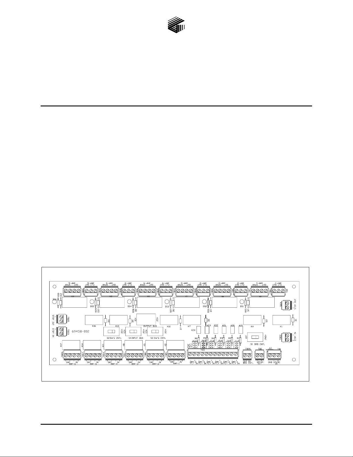
The Model 12599-002 Hot Standby Amplifier Module is designed for use in system cabinets equipped
with central power amplif iers requiring hot ( aut o matic) switchin g of a standby ( backu p) a mplifier wh e n
any one of the pr imary power amplifiers fail.
This module provides prioritized switching for either six single-channel power amplifiers, or three dualchannel amplifiers with up to 700 watts of output power per channel. Also, multiple modules can be
cas c aded using an “in/out” boa rd contro l feat ure.
Figure 1. Model 12599-002 Hot Standby Amplifier Module
(Switches shown in factory default position)
GAI-Tronics Corporation 400 E. Wyomissing Av e. Mohnton, PA 19540 USA
610-777-1374 800-492-1212 Fax: 610-796-5954
ISIT WWW.GAI-TRONICS.COM FOR PRODUCT LITERATURE AND MANUALS
V
Page 2
Pub. 42004-412A
Model 12599-002 Hot Standby Amplifier Module Page: 2 of 17
Hardware Configuration
The Model 12599-002 Hot Standby Amplifier Module is a printed circuit board assembly (PCBA)
equipped with plug-in t ype t ermina l blocks, six high-current r elays f or swit chi n g amplifi er outputs , and
12 lo w- pow er relays for switchi ng a mplifi er inputs and providing dry cont act sta tus outputs.
The module is also equipped with five slide switches for mode select functions, and six LEDs to indicate
act ively sw itch ed circ u i ts. Each fault detect input is c omprised of a Phot o -MOS relay with ju mper clips
(J1–J12) to select “wet” or “dry” activation. Each activation type is briefly described below:
Wet Activation – requires an active source voltage of 10–15 V dc from the amplifier when healthy and
remo val of t he volt age when the ampl ifier is fau l ted.
Dry Activation – re quir es a normally closed (N .C.), dr y cont act f rom the amplifier wh e n healthy a nd
removal of the contact when the amplifier is faulted. This setting is also used when the amplifier has an
open collector fault output, which is actively low (sinking to dc common) when healthy, and floating high
when the amplifier is faulted.
OTE: Jumper clips J1–J12 are set-up in pairs, and each pair must be set to the same position for its
N
respective input. The following table depicts the corresponding input and jumper pair, and the mode of
oper ation bas e d o n the jumper c lip position.
Fault
Input
Jumper
Clips
Wet
Mode
Dry
Mode
Fault
Input
Jumper
Clips
Wet
Mode
Dry
Mode
1 J1 & J2 Pos. 1–2 Pos. 2–3 4 J7 & J8 Pos. 1–2 Pos. 2–3
2 J3 & J4 Pos. 1–2 Pos. 2–3 5 J9 & J10 Pos. 1–2 Pos. 2–3
3 J5 & J6 Pos. 1–2 Pos. 2–3 6 J11 & J12 Pos. 1–2 Pos. 2–3
\\s_eng\gtc proddoc s \st andard iom s - current release\42004 instr. manuals \ 42004-412a. doc
06/08
Page 3

Pub. 42004-412A
Model 12599-002 Hot Standby Amplifier Module Page: 3 of 17
Installation
WARNING
Disconnect power for safety when installing or replacing the module.
The Model 12599-002 Hot Standby Amplifier Module measures 12 L× 4 W × 1.5 H inches (305 × 102 ×
31.75 mm) and is designed for mounting on 4-inch Snap Trak.
Carefully press the module edges into the SnapTrak to avoid damage to the module’s PCBA and/or
components. Once installed, ensure the module edges are secured in the channels so that the module does
not dislodge during transport or operation if subjected to vibration.
Also, if this module is used with other (cascaded) modules, a 1-inch (25.4-mm) spacing between modules
will facilitate wiring at the edge-mounted terminal blocks.
Terminations
The Model 12599-002 Hot Standby Amplifier Module is equipped with modular (plug-in type) terminal
blocks. T hese modular termina l bloc ks simplify external wire connections duri ng inst allati on, an d
provide quick disco n nect if replaceme nt is ever r e quire d.
The following is a breakdown of each terminal block and its function(s):
TB1 – is the 12 V dc power input to the module.
TB2 – is a 12 V dc power output to another (cascaded) module or another 12 V dc-powered device.
TB3 – is the Amp-1 through Amp-6 fault inputs. The + and - terminals connect to the amplifier’s fault
outp ut, which can b e a wet (acti ve) output or a dry, normally cl osed contact. Sinc e each fault input
operates independently, amplifiers with different fault output types can be simultaneously connected to
this module’s inputs. The following details the different types of amplifier fault outputs, and the required
jumper settings. See Note 1.
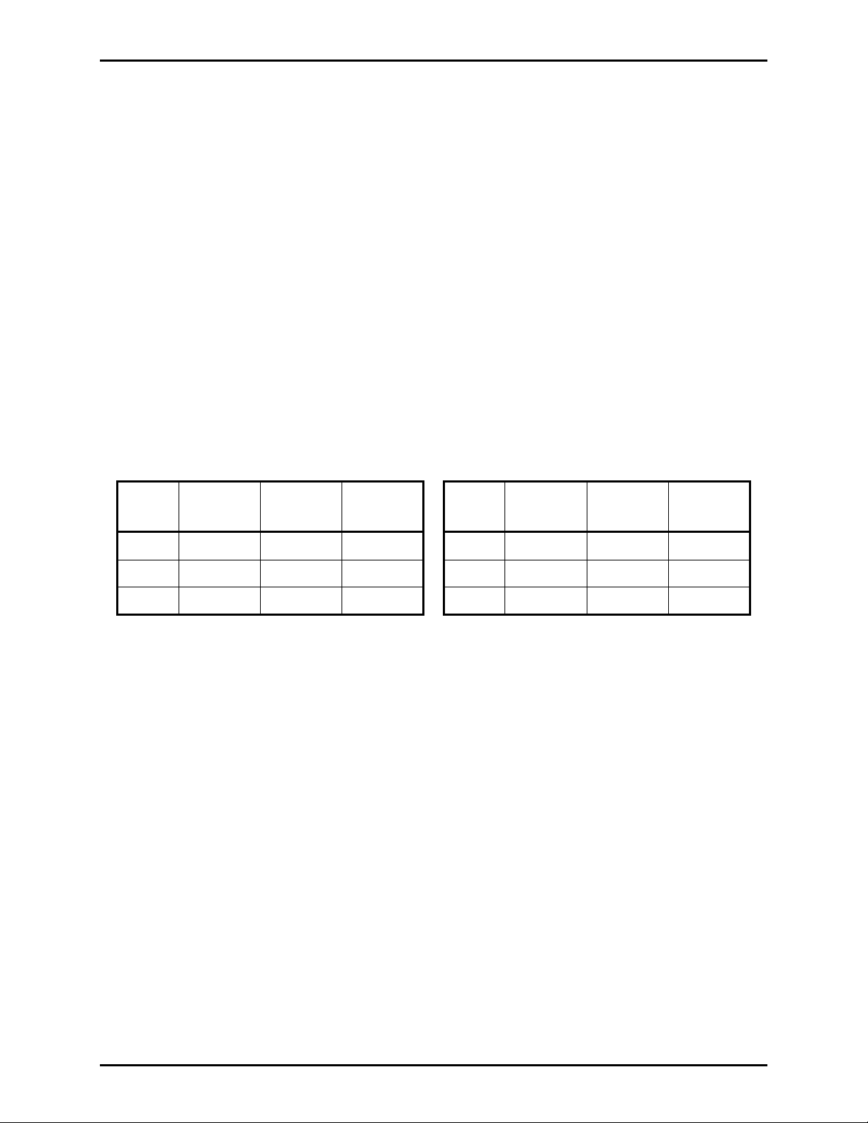
WET (ACTIVE) OUTPUT – requires the amplifier to output 10–15 V dc when operating in a healthy state
and the respective jumper clips set to the wet position. Be sure to match polarity markings, e.g., + to +
(plus to plus) and – to –
(minus to minus) between the amplifier’s fault output and input terminals at this
module for proper operation. Refer to Figure 2 for a connection detail.
D
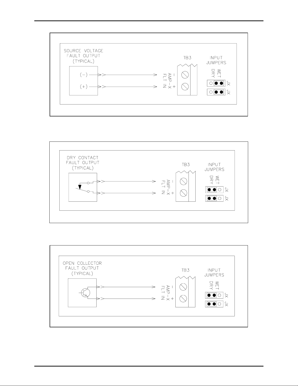
RY (N.C.) CONTACT OUTPUT – requires the a mplifier to pr ovide a dry, n ormally closed cont act when
oper atin g in a healthy sta te and the res pective jumper clip s set t o the dry pos ition. Con nection of t he
amplifier’s normally closed fault contact connects across the + (plus) a nd – (minus) terminals at the
module. Refer to Figure 3 for a connection detail.
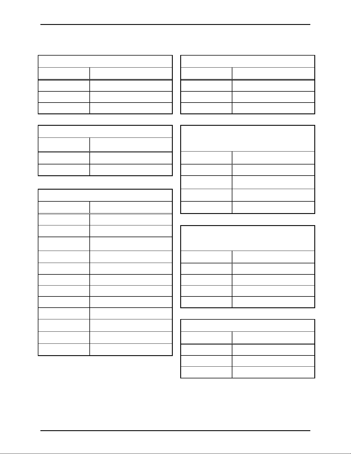
O
PEN COLLECTOR (ACTIVE LOW) – requires the amplifier to provide an active low output (sinking to dc
common) when operating in a healthy state, and the respective jumper clips to be set to the dry position.
Connection of the amplifier’s fault output has the input (common or emitter) side connected to the +
(plus) terminal, and the output (collector) connected to the – (minus) terminal for proper operation. Refer
to Figure 4 for a connection detail.
\\s_eng\gtc proddoc s \st andard iom s - current release\42004 instr. manuals \ 42004-412a. doc
06/08
Page 4

Pub. 42004-412A
Model 12599-002 Hot Standby Amplifier Module Page: 4 of 17
TB4, TB7, TB 10, TB13, TB16 and TB19 – are dry output contacts for Amp-1 through Amp-6 faults
respectively. Each contact set is a Form “C” type. The maximum switching capacity for each contact set
is 24 V dc @ 1 amp and can be used for triggering a remote status indicator or for an input at a supervised
system device for a visual text display. See Note 5.
TB5, TB8, TB 11, TB14, TB17 and TB20 – are the audio source and input connections for Amp-1
through Amp-6. The amplifier’s audio source is connected at the
SRC (source) terminals. The
amplifier’s input is connected at the IN (input) terminals. Be sure to observe polarity markings at these
termina ls for proper operation and au dio performance. Ref er to F igur e 5 .
TB6, TB9, TB 12, TB15, TB18 and TB21 – are the audi o outpu t and s peaker line connections for
Amp-1 through Amp-6. The active amplifier output (e.g., 4-ohm, 8-ohm, 16-ohm, 25 V, 70 V or 100 V)
is connect ed a t th e
module at the
OUT (output) terminal. The designated speaker(s) or speaker line connects to the
SPKR (speaker) terminals. Be sure to observe polarity markings at these terminals for
proper opera tion a nd audio performance. R efer t o Figure 6.
TB22
– is where the standby amplifier input connects if using a single-channel amplifier. If using a dual-
channel amplifier, connect the channel 1 input to these terminals. See Note 2 and refer to Figure 7 and
Figure 8.
– is for busing the standby amplifier input to another (cascaded) module when using a single-
TB23
channel amplifier. However, if a dual-channel amplifier is used with the module, the channel 2 input of
the standby amplifier should connect to these terminals. See Note 2 and refer to Figure 7 and Figure 8.
TB24 – is where the standby amplifier output connects if using a single-channel amplifier. If using a
dual-channel amplifier connect the channel 1 output to these terminals. See Note 2 and refer to Figure 7
and F igur e 8 .
TB25 – is for busing the s tandby a mplifier output to a nother (ca scaded) module w hen us ing a single channel amplifier. However, if a dual-channel amplifier is used with the module, then the channel 2
outp ut of the st andb y ampl ifier shou ld co nnect to these t erminals. See Note 3 and refer to Figure 7 and
Figure 8.
TB26 – is the
BRD CNTL (boa rd control) IN (input ) and OUT (output), which is used in a cascade
arrangement of multiple modules. In a cascade arrangement, no connection is made at the IN terminal at
the first module. For the second module in the cascade, connect the
OUT terminal of the first module to
IN terminal of the second module, and continue this wiring scheme across subsequent modules in the
cas cade. See Note 4 a nd ref er to F i gur e 7 and Figur e 8 .
OTES:
N
1. When the module is operated in 2-channel (dual-channel) mode, the Amp-4, Amp-5 and Amp-6 fault
inputs are not used, and a jumper must be wired across each unused input terminal set at TB3. Also,
the respective input jumper clips must be set to the dry position to prevent false activation of unused
fault input circuits.
2. To use both inputs of a dual-channel standby amplifier across multiple cascaded modules, wire TB22
and TB23 in p arallel (respe c tive ly) across all modules.
3. To use both outputs of a dual-cha n nel st andby ampl ifier acr oss multiple cascaded modul es , wir e
TB24 and TB25 in parallel (respectively) across all modules.
4. Most central amplifier system applications usually employ or specify a ratio of one standby amplifier
for every five or six primary amplifiers to minimize the risk of lost coverage. Be sure to check the
specified system requirements for the ratio of standby (backup) amplifiers to primary amplifiers.
5. When the module is operated in 2-channel (dual-channel) mode, the Amp-4, Amp-5 and Amp-6 fault
output contact are not used at TB13, TB16 and TB19 respectively.
\\s_eng\gtc proddoc s \st andard iom s - current release\42004 instr. manuals \ 42004-412a. doc
06/08
Page 5
Pub. 42004-412A
Model 12599-002 Hot Standby Amplifier Module Page: 5 of 17
Figure 2. Source Voltage (Active) Fault Connection
Figure 3. Dry Conta c t Fault Con nect ion
Figure 4. Open Collect or Fault Connecti on
\\s_eng\gtc proddoc s \st andard iom s - current release\42004 instr. manuals \ 42004-412a. doc
06/08
Page 6
Pub. 42004-412A
Model 12599-002 Hot Standby Amplifier Module Page: 6 of 17
The f ollow ing is a summa ry of a ll terminal block fu nc tion( s). N umber referenc es sho wn in the followi ng
tables are from right to left when viewed from the edge of the module.
TB1 – 12 V dc Power Input
Terminal Ref. Function Terminal Ref. Function
TB4 – Amp-1 Fault Contact Output
1 12 V dc positive (+) 1 Normally Open Contact
2 12 V dc negative (-)
3 Ground (optional)
2 Normally Closed Contact
3 Common Contact
TB2 – 12 V dc Output
Terminal Ref. Function
1 12 V dc positive (+)
2 12 V dc negative (-)
TB3 – Amplifier Fault Control Inputs
Terminal Ref. Function
1 Amp-1 Fault Input (+)
TB5 – Input and Source
Amp-1 (Single Channel Mode)
Amp-1, Ch-1 (Dual Channel Mode)
Terminal Ref. Function
1 Amplifier Input (+)
2 Amplifier Input (-)
3 Audio Signal Source (+)
4 Audio Signal Source (-)
TB6 – Output and Speaker
2 Amp-1 Fault Input (-)
3 Amp-2 Fault Input (+)
4 Amp-2 Fault Input (-)
5 Amp-3 Fault Input (+)
6 Amp-3 Fault Input (-)
7 Amp-4 Fault Input (+)
8 Amp-4 Fault Input (-)
9 Amp-5 Fault Input (+)
10 Amp-5 Fault Input (-)
11 Amp-6 Fault Input (+)
12 Amp-6 Fault Input (-)
Amp-1 (Single Channel Mode)
Amp-1, Ch-1 (Dual Channel Mode)
Terminal Ref. Function
TB7 – Amp-2 Fault Contact Output
Terminal Ref. Function
1 Amplifier Input (+)
2 Amplifier Input (-)
3 Audio Signal Source (+)
4 Audio Signal Source (-)
1 Normally Open Contact
2 Normally Closed Contact
3 Common Contact
\\s_eng\gtc proddoc s \st andard iom s - current release\42004 instr. manuals \ 42004-412a. doc
06/08
Page 7

Pub. 42004-412A
Model 12599-002 Hot Standby Amplifier Module Page: 7 of 17
TB8 – Input and Source
Amp-2 (Single Channel Mode)
Amp-2, Ch-1 (Dual Channel Mode)
Terminal Ref. Function Terminal Ref. Function
TB12 – Output and Speaker
Amp-3 (Single Channel Mode)
Amp-3, Ch-1 (Dual Channel Mode)
1 Amplifier Input (+) 1 Speaker Line (+)
2 Amplifier Input (-) 2 Speaker line (-)
3 Audio Signal Source (+) 3 Amplifier Output (+)
4 Audio Signal Sourc e (-) 4 Amplifier Output (-)
TB9 – Output and Speaker
Amp-2 (Single Channel Mode)
Amp-2, Ch-1 (Dual Channel Mode)
Terminal Ref. Function Terminal Ref. Function
TB13 – Amp-4 Fault Contact Output
1 Speaker Line (+) 1 Normally Open Contact
2 Speaker Line (-) 2 Normally Closed Contact
3 Amplifier Output (+) 3 Common Contact
4 Amplifier Output (-)
TB14 – Input and Source
Amp-4 (Single Channel Mode)
Amp-1, Ch-2 (Dual Channel Mode)
TB10 – Amp-3 Fault Contact Output Terminal Ref. Function
Terminal Ref. Function
1 Amplifier Input (+)
1 Normally Open Contact 2 Amplif i er Input (-)
2 Normally Closed Contact 3 Audio Signal Source (+)
3 Common Contact 4 Audio Signal Source (-)
TB11 – Input and Source
Amp-3 (Single Channel Mode)
Amp-3, Ch-1 (Dual Channel Mode)
Terminal Ref. Function Terminal Ref. Function
TB15 – Output and Speaker
Amp-4 (Single Channel Mode)
Amp-1, Ch-2 (Dual Channel Mode)
1 Amplifier Input (+) 1 Speaker Line(+)
2 Amplifier Input (-) 2 Speaker Line (-)
3 Audio Signal Source (+) 3 Amplifier Output (+)
4 Audio Signal Sourc e (-) 4 Amplifier Output (-)
\\s_eng\gtc proddoc s \st andard iom s - current release\42004 instr. manuals \ 42004-412a. doc
06/08
Page 8

Pub. 42004-412A
Model 12599-002 Hot Standby Amplifier Module Page: 8 of 17
TB16 – Amp-5 Fault Contact Output TB19 – Amp-6 Fault Contact Output
Terminal Ref. Function
Terminal Ref. Function
1 Normally Open Contact 1 Normally Open Contact
2 Normally Closed Contact 2 Normally Closed Contact
3 Commo n Contact 3 Co mmon Contact
TB17 – Input and Source
Amp-5 (Single Channel Mode)
Amp-2, Ch-2 (Dual Channel Mode)
Terminal Ref. Function
TB20 – Input and Source
Amp-6 (Single Channel Mode)
Amp-3, Ch-2 (Dual Channel Mode)
Terminal Ref. Function
1 Amplifier Input (+) 1 Amplifier Input (+)
2 Amplif i er Input (-) 2 Amplifier Input (-)
3 Audio Signal Source (+) 3 Audio Signal Source (+)
4 Aud i o Signal S our ce (-) 4 Audio Signal Source (-)
TB18 – Output and Speaker
Amp-5 (Single Channel Mode)
Amp-2, Ch-2 (Dual Channel Mode)
Terminal Ref. Function
TB21 – Output and Speaker
Amp-6 (Single Channel Mode)
Amp-3, Ch-2 (Dual Channel Mode)
Terminal Ref. Function
1 Speaker Line (+) 1 Speaker Line (+)
2 Speaker Line (-) 2 Speaker Line (-)
3 Amplifier Output (+) 3 Amplifier Output (+)
4 Amplifier Output (-) 4 Amplifier Output (-)
\\s_eng\gtc proddoc s \st andard iom s - current release\42004 instr. manuals \ 42004-412a. doc
06/08
Page 9

Pub. 42004-412A
Model 12599-002 Hot Standby Amplifier Module Page: 9 of 17
TB22 – Input
Standby Amp (Single Channel Mode)
Standby Amp, Ch-1 (Dual Channel Mode)
Terminal Ref. Function
TB25 – Output, or
Feed-Thru (Single Channel Mode) Standby
Amp, Ch-2 (Dual Channel Mode)
Terminal Ref. Function
1 Amplifier Input (-) 1 Amplifier Out p ut (-)
2 Amplifier Input (+) 2 Amplifier Output (+)
TB23 – Input, or
Feed-Thru (Single Channel Mode) Standby
Amp, Ch-2 (Dual Channel Mode)
Terminal Ref. Function
TB26 – Board Control
Terminal Ref. Function
1 Board Co ntrol IN
1 Amplifier Output (-) 2 Board Control OUT
2 Amplifier Output (+)
TB24 – Output
Standby Amp (Single Channel Mode)
Standby Amp, Ch-1 (Dual Channel Mode)
Terminal Ref. Function
1 Amplifier Output (-)
2 Amplifier Output (+)
\\s_eng\gtc proddoc s \st andard iom s - current release\42004 instr. manuals \ 42004-412a. doc
06/08
Page 10

Pub. 42004-412A
Model 12599-002 Hot Standby Amplifier Module Page: 10 of 17
Figure 5. Input Connections
Figure 7. Cascaded modules operated in single-channel mode
Figure 6. Output Connections
Figure 8. Cascaded mo dules operated i n dual - channel mode
\\s_eng\gtc proddoc s \st andard iom s - current release\42004 instr. manuals \ 42004-412a. doc
06/08
Page 11

Pub. 42004-412A
Model 12599-002 Hot Standby Amplifier Module Page: 11 of 17
Operation
The Model 12599-002 Hot Standby Amplifier Module operates from a 12 V dc power source. With
power applied, all switches properly set and all inputs properly connected, no circuits should be active
until an amplifier fault occurs. The block diagrams below depict typical circuit functions when the
modu le is opera ted in either single or dual-chan nel modes.
Figure 9. Block D i agram – S ingle-channel operatio n
\\s_eng\gtc proddoc s \st andard iom s - current release\42004 instr. manuals \ 42004-412a. doc
06/08
Page 12

Pub. 42004-412A
Model 12599-002 Hot Standby Amplifier Module Page: 12 of 17
Figure 10. Block Dia gram - Dua l - c hann e l operat ion
\\s_eng\gtc proddoc s \st andard iom s - current release\42004 instr. manuals \ 42004-412a. doc
06/08
Page 13

Pub. 42004-412A
Model 12599-002 Hot Standby Amplifier Module Page: 13 of 17
Theory of Operation
The Amp-1 through Amp-6 fault inputs at TB3 on the Model 12599-002 Hot Standby Amplifier Module
provide a single connection point for each amplifier fault output. The module’s fault inputs can be
configured to accept a range of amplifier fault output types, and each is described in the following text:
Wet Mode – Active Fault Output
When the input jumper clip pair is set to the wet position, the + (plus) terminal accepts a positive dc
voltage and the - (minus) terminal accepts negative (dc common) voltage from the amplifier’s internal
fault circuit. When the connected power amplifier is healthy, the amplifier fault output signal to these
terminals must be active.
If the amplifi er’s internal fault c ircuits detect a pr oblem (e.g., a shorted or overloaded ou tput, excessive
temperature, etc.), or ac power is removed from the amplifier, the amplifier’s fault output is no longer
producing an active output voltage. The associated input circuit detects this change, and activates the
associated relay group to switch the standby amplifier in place of the faulty amplifier. The circuit will
remain active until the amplifier fault condition remedied.
Dry Mode – N.C. Faul t Conta ct
When the input jumper clip pair is set to the dry position, the + (plus ) and - (minus) terminals accept a
normally closed, dry contact from the amplifier’s internal fault circuit. If the amplifier’s internal fault
circ uits detec t a proble m (e.g., a s horte d or overloaded outpu t, excessive t e mperatu re, etc .), or ac pow er is
removed from the amplifier, the amplifier’s fault output contact opens. The associated input circuit
detects this change, and activates the associated relay group to switch the standby amplifier in place of the
faulty amplifier. The circuit will remain active until the amplifier fault condition remedied.
Dry Mo de – Active O pen Coll ector Fault Output
When the input jump er c lip pa ir is set to the D
RY position, the + (plus) terminal connects to the “input”
(or emitter) side of the amplifier’s fault terminals, and the - (minus) terminal connects to the output (or
Collector) side of the amplifier’s fault terminals. When the connected power amplifier is healthy, the
amplifier fault output must be actively low (sinking to dc common) to the – (minus) terminal, of this
module’s input.
If the amplifi er’s internal fault c ircuits detect a pr oblem (e.g., a shorted or overloaded ou tput, excessive
temperature, etc.), or ac power is removed from the amplifier, the amplifier’s fault output floats high. The
associated input circuit detects this change, and activates the associated relay group to switch the standby
amplifier in place of the faulty amplifier. The circuit will remain active until the amplifier fault condition
remedied.
Priority Switching
The 12599-002 Hot Standby Amplifier Module prioritizes the switching of the standby amplifier for two
reasons, which are:
1. To avoid excessive loading of the standby amplifier in the event of multiple amplifier failures, and
2. To ensure that critical facility areas receive alarm and voice audio broadcasts during emergencies.
The order of priority switching is from highest to lowest; Amp-1 has highest priority and Amp-6 has
lowest priority. This prioritization scheme applies if the board is operated in either 1-channel or 2cha nn e l mode s. If c a scade d with other modul e s, mo dule 1 has a higher priority than module 2, and
module 2 has higher priority than module 3, etc.
\\s_eng\gtc proddoc s \st andard iom s - current release\42004 instr. manuals \ 42004-412a. doc
06/08
Page 14

Pub. 42004-412A
Model 12599-002 Hot Standby Amplifier Module Page: 14 of 17
While it is diffic u l t to deter mine which area of a facility is the most c riti c al (as in ite m 2 above) , an
example would be an offshore oil platform system with multiple amplifiers. In this case, the living
quarters (LQ) are usually considered such an area. In this type of system/cabinet design, the LQ amplifier
should be connected to the Amp-1 terminals to ensure that personnel (sleeping in the LQ) will be alerted
during emergencies.
Dry Cont act Output s
The Model 12599-002 Hot Standby Amplifier Module provides six, Form “C” dry contact outputs (one
per amplifier circuit) that can be used for triggering either a remote status indicator, or an input at a
supervised system device for visual text display. Each output contact operates in conjunction with its
respective fault detection circuit so that the status of all connected amplifiers can be monitored at all
times, regardless of their priority assignment.
Cascading Modules
The Model 12599-002 Hot Standby Amplifier Module can be operated with a series of other modules in a
cascade. This feature is useful in cabinet/system applications when the following criteria must be met:
• A higher ratio of primary (active) amplifiers to a standby amplifier is needed, or
• In particular, when dual-channel amplifiers are employed.
When using the ca scade fea ture, the
cas c ade to function properly, connect the
second module. Do not make any connections to the IN
IN/OUT control at TB26 must be used between modules. For the
OUT terminal of the first module to the IN terminal at the
terminal at the first module. For subsequent
modules in the cascade, this in/out wiring arrangement must continue across all modules.
In addition to in/out control across modules, the mode switches S1 through S5 must also be set to the
proper operating position. See the Mode Switches (S1–S5) section below for information on the function
and settings of these switches.
Mode Swi tches (S1– S5)
The Model 12599-002 Hot Standby Amplifier Module is equipped with five mode control switches. The
functio n of eac h is swit ch is described below:
S1 Brd Cntl (Board co ntrol ) – Sinc e relay switching on this modul e is pr ioriti zed, this sw itch de ter mi nes
if the module is operated as standalone, the first of multiple modules, or is operating behind another
module. If the module is used standalone, or is the first of multiple modules, the switch must be set to the
ST position. Howev er, if the mo dule opera tes b e hind another module in a cascade d control path, the
1
switch must be set to the
2ND+ position.
S2/S3 Sw’g Cnt l (Switching control) – Since this module is designed to switch either six single-channel
amplifiers or three dual-channel amplifiers, these two switches must be set to the appropriate position for
the type of amplifier being switched, e.g.,
1CH (1-channel) or 2CH (2-cha n nel) respectivel y. (S ee the
note below.)
When t he switches a re s et to the
control from their respective fault input circuits. When the switches are set to the 2CH
1CH position, all six relay circuit groups operate independently via
position, the
Amp-1/Amp-4 circuits, Amp-2/Amp-5 circuits, and Amp-3/Amp-6 circuits are linked for switching both
channels of the a mplifier simu ltan eousl y.
\\s_eng\gtc proddoc s \st andard iom s - current release\42004 instr. manuals \ 42004-412a. doc
06/08
Page 15

Pub. 42004-412A
Model 12599-002 Hot Standby Amplifier Module Page: 15 of 17
S4 Input Bus – This switch allows the input signal bus to function across all six relay circuits for six
single-channel amplifiers, or be split for three dual-channel amplifiers. Thus, if switches S2 and S3 are
set to either
1CH or 2CH, this switch must also be set to the same operating mode. See the note below.
S5 Output Bus – This switch allows the output signal bus to function across all six relay circuits for six
single-channel amplifiers, or be split for three dual-channel amplifiers. Thus, if switches S2, S3 and S4
are set to either
1CH or 2CH, this switch must also be set to the same operating mode. See the note
below.
NOTE
Switches S2, S3, S4 and S5 must be set to the same operating position. Do NOT operate any of the
switc h es in oppo site positions as this wi ll resu lt in improper op erat ion of t his module .
Maintenance
The Model 12599-002 Hot Standby Amplifier Module does not contain any user serviceable parts. Do
attempt to make any repairs to the module.
not
If the module re quires service, c o ntact your Regional Ser vice Ce nter f or a r et urn authorization number
(RA# ) . The module should be s hipp e d prepaid t o GAI- T ronics with a ret urn authorization numb er and a
purchase order number. If the module is under warranty, repairs or a replacement will be made in
accordance with GAI-Tronics’ warranty policy. Please include a written explanation of all defects to
assist our technicians in their troubleshooting efforts.
Call 800-492-1212 inside the USA or 610-777-1374 outside the USA for help identifying the Regional
Service Center closest to y o u.
\\s_eng\gtc proddoc s \st andard iom s - current release\42004 instr. manuals \ 42004-412a. doc
06/08
Page 16

Pub. 42004-412A
Model 12599-002 Hot Standby Amplifier Module Page: 16 of 17
Troubl eshooting
Problem Solution
Module is damaged. Do not attempt to repair the module.
Contact GAI-Tronics service for repair or replacement of the
module in accordance with the information provided on page 15.
Module does not switch to backup
amplifier when any of the primary
amplifiers fail or are powereddown.
Unused circuits are energized.
Relay switching activity can be
heard on the module and output
cont acts are functioning.
But the associated LED does not
illu minate and the primary au dio
lines are not switching to the
standby ( backu p) amplif ier.
Amplifier 4 switches when
amplifier 1 fails. Likewise,
amplifier 5 swit ches wh en amplifier
2 fa ils , and amplif ier 6 s wit ches
when amplif ier 3 fails.
Check polarity of wiring between fault inputs at the module, and
the fault outputs at each amplifier. If using an amplifier equipped
with a RJ-11 fault output connector, a reversal of the cable leads
should correct the problem.
Also, be sure the input jumper clips (J1–J12) are set to the correct
position for either wet or dry mode, based on the fault output type
produced by amplif ier.
Set the designated input jumper clips to the dry position (as
defined on page 2) and install a jumper across any/all unused
fault inputs.
If the module is used standalone or is the first in a cascade, set the
BRD CNTL switch S1 to the 1ST position, as described in the
Theory of O peration section.
Be sure switches S2 through S5 are set to the 1CH position when
using single-channel (monaural) amplifiers, as described in the
Theory of O peration section.
Both channels of the amplifiers are
not switching si multaneous ly whe n
faulted.
Amplifiers on the second
(cas ca d ed) mo dul e op er a te
independently.
Be sure switches S2 through S5 are set to the 2CH position when
usin g dual-cha nnel (stereo) ampl ifier s, as des c rib e d as desc rib e d
in the Theory of Operation section.
In a cascade arrangement, switch S1 must be set to the 1ST
position at the first module, and the
modu le, and all s u bsequent module s, a s descr ibed i n the Theory
of Operation se c tion.
Also, be sure wiring at the
conf orms to Fi gure 5 or Figure 6 respect ivel y.
After performing all wiring checks,
tr ouble-shooting, etc . as describe d
Contact GAI-Tronics service for repair or replacement of the
module in accordance with the information provided on page 15.
in this section, the module still does
not function properly.
\\s_eng\gtc proddoc s \st andard iom s - current release\42004 instr. manuals \ 42004-412a. doc
06/08
2ND+ position at the second
IN/OUT CNTL terminals at TB26
Page 17

Pub. 42004-412A
Model 12599-002 Hot Standby Amplifier Module Page: 17 of 17
Specification s
Electrical
Power requirements............................................................................... 9.5 to 14 V dc (12 V dc nominal)
Current draw .............................................................................................. 300 mA maximum @ 12 V dc
Number of amplifier inputs.................................................................. 6-single channel or 3-dual channel
Fault input terminal voltage (Wet mode)........................................................................12 V dc (nominal)
Fault input voltage range (Wet mode)............................................10–15 V dc (active); <8 V dc (inactive)
Fault input circuit current (Wet mode)............................................................................................1.2 mA
Number of fault output contacts................................... 6 (single-channel mode) or 3 (dual-channel mode)
Fault output contact type ................................................................................................ Single Form “C”
Fault output contact rating................................................................................. 2 A maximum @ 30 V dc
Amplifi er Audio S witchin g
Amplifier type........................................................................................................ Single or dual-cha nnel
Audio input levels (typical per circuit)................................ 600 ohm @ 0.775 Vrms (0 dBm) to 1.5 Vrms
Amplifier output power (maximum per circuit)............................................. 700 watts (100% duty cycle)
Speaker load switching.................................................................................. Standard 4, 8 or 16-ohms, or
25 V, 70 V or 100 V constant voltage lines
Terminations
Type..................................................................................................... Modular (plug-in) terminal blocks
Minimum conductor size...................................................................................... No. 28 AWG (0.5 mm
Maximum conductor size...................................................................................... No. 12 AWG (3.0 mm
2
2
Mechanical
Module dimensions .................................... 12.00 L × 4.00 W × 1.25 H inches (304.8 × 101.6 × 31.7 mm)
Module weight................................................................................................................. 1. 1 lbs. ( 0.5 kg)
Enviro nmental
Temperature range (operating/storage)...................................................... 32° F to 140° F (0° C to 60° C)
Humidity ........................................................................................85% relative non-condensing humidity
)
)
\\s_eng\gtc proddoc s \st andard iom s - current release\42004 instr. manuals \ 42004-412a. doc
06/08
 Loading...