

Page 1

Pub. 42004-375A
GAI-TRONICS® CORPORATION
A HUBBELL COMPANY
Model 12599-001
Hot Standby Amplifier Mo dule
Confidentiality Notice
This manua l is provide d sole ly as an operatio nal, installation, and ma inte nance guide and conta ins
sensitive business and t e chnical informatio n tha t is confidentia l and pr opri et ary to GAI- Tronics.
GAI-Tronics retains all intellectual property and other rights in or to the information contained herein,
and such information may only be used in connection with the operation of your GAI-Tronics product or
system. This manu al may not be dis clos e d in any form, in whole or in pa rt, direct ly or i ndir ectly, to a ny
third pa r ty.
General Information
The Model 12599-001 Hot Standby Amplifier Module is designed for use in system cabinets equipped
with central power amplif iers requiring hot ( aut o matic) switchin g of a standby ( backu p) a mplifier wh e n
any one of the pr imary power amplifiers fail.
This module provides prioritized switching for either six single channel power amplifiers, or three dualchannel amplifiers with up to 720 watts of output power per channel. Also, multiple modules can be
cascaded using an in/out board control feature.
Figure 1. Model 12599-001 Hot Standby Amplifier Module
(Switches shown in factory default position)
GAI-Tronics Corporation P.O. Box 1060, Readi ng, PA 19607-1060 USA
610-777-1374 800-492-1212 Fax: 610-796-5954
ISIT WWW.GAI-TRONICS.COM FOR PRODUCT LITERATURE AND MANUALS
V
Page 2

Pub. 42004-375A
Model 12599-001 Hot Standby Amplifier Module Page: 2 of 11
Hardware Configuration
The Model 12599-001 Hot Standby Amplifier Module is a printed circuit board assembly (PCBA)
equipped with plug-in type terminal blocks, six high current relays for switching amplifier outputs, and 12
low-power relays for switching amplifier inputs and providing dry contact status outputs.
The module is also equipped with five slide switches for mode select functions, and six LEDs to indicate
actively switched circuits. The fault detection inputs are comprised of a Quad Comparator and Darlington
Arr ay for opera ting the re lay switching circuits.
Installation
The Model 12599-001 Hot Standby Amplifier Module is designed for mounting on 4-inch Snap Trak®
and measures 12 H× 4 W × 1.5 L inches (305 × 102 × 31.75 mm).
When installing or replacing this module, be sure to disconnect power for safety. When inserting the
module in SnapTrak
to the module’s printed circuit board and/or components. Once installed in the SnapTrak
®
, exer cise ca re when p ressing the m odule edg es in to the SnapT rak® to avoid damage
®
, be sure the
module edges are secured in the channels so that the module does not dislodge during transport or
oper atio n if subjected to v ibra tion. Also, if this modul e is used w ith other (cascaded) modu les, a one-inch
(25.4-mm) spacing between modules will facilitate wiring at the edge mounted terminal blocks.
Terminations
The Model 12599-001 Hot Standby Amplifier Module is equipped with modular (plug-in type) terminal
blocks. T hese modular termina l bloc ks simplify external wire connections duri ng inst allati on, an d
provide quick disco n nect if replaceme nt is ever r e quire d.
The following is a breakdown of each terminal block and its function(s):
TB1 – is the 12 V dc power input to the module.
TB2 – is a 12 V dc power output to anoth er (cascaded) modu le or anoth er 12 V dc pow ered d e vice.
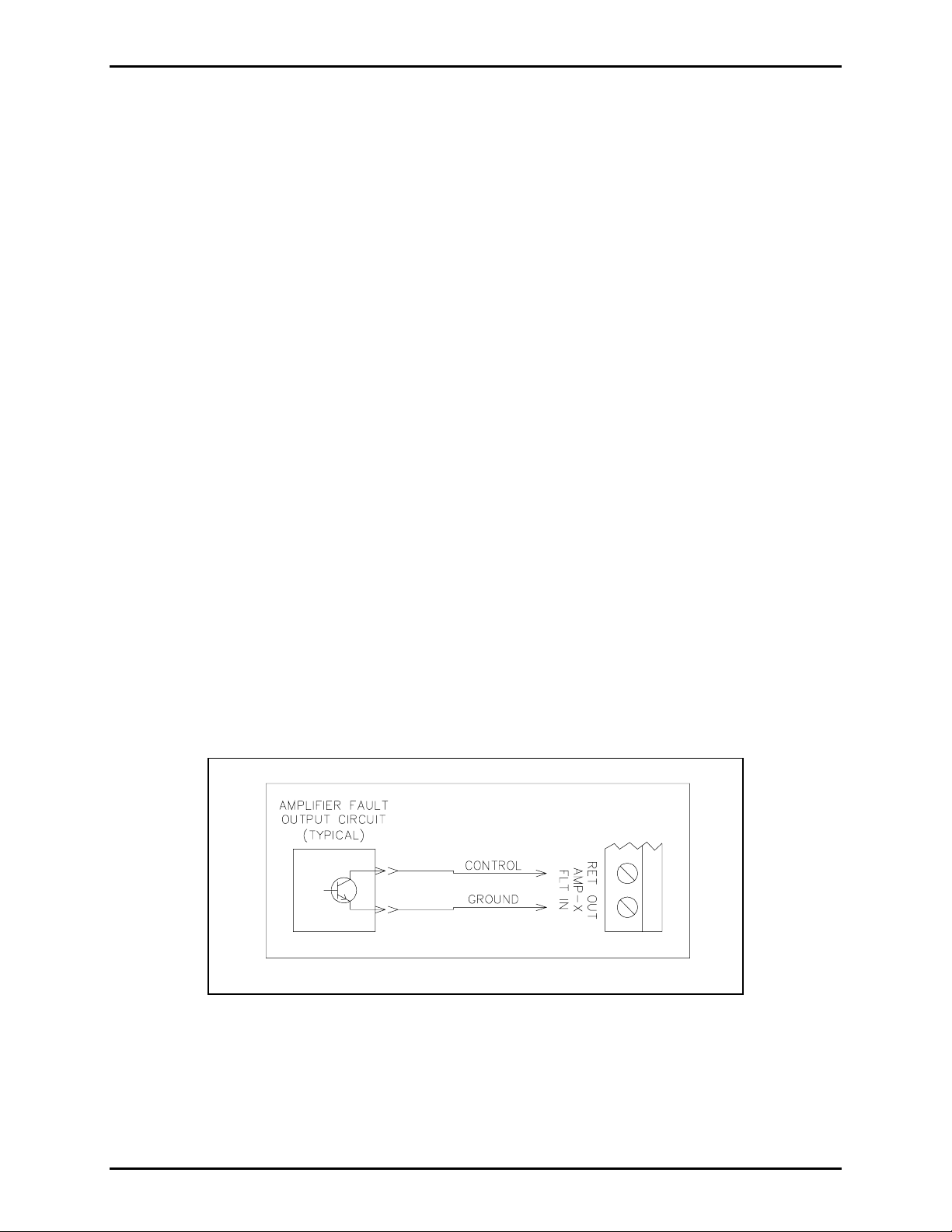
TB3 – is where the Amp-1 through Amp-6 fault inputs connect. The OUT ter mi nal is dc common an d
connects to the input side of the amplifier’s internal fault circuit. The RET terminal connects to the
output of the amplifier’s internal fault circuit. Refer to Figure 2.
TB4, TB7, TB 10, TB13, TB16 and TB19 – are dry output contacts for Amp-1 through Amp-6 faults
respectively. Each contact set is a form “C” type. The maximum switching capacity for each contact set
is 24 V dc @ 1 amp and can be used for triggering a remote status indicator or an input at a supervised
system device for visual text display.
TB5, TB8, TB 11, TB14, TB17 and TB20 – are the audio source and input connections for Amp-1
through Amp-6. The SRC (sourc e) t ermina l s a re where the a mpl i fi er’s a udio source is con necte d . The
IN (input) terminals are where the amplifier’s input is connected. Be sure to observe polarity markings at
these termina l s for proper opera tion a nd aud io performance. Refer t o Figur e 3.
TB6, TB9, TB 12, TB15, TB18 and TB21 – are the audi o outpu t and s peaker line connections for
Amp-1 through Amp-6. The OUT (output) terminal is the where the active amplifier output (e.g., 4-ohm,
8-ohm, 16-ohm, 25 V, 70 V or 100 V) is connected. The SPKR (speak er) terminals are wh ere the
designated speaker(s) or speaker line connects to the module. Be sure to observe polarity markings at
these termina l s for proper opera tion a nd aud io performance. Refer t o Figur e 4.
\\s_eng\gtc proddoc s \st andard iom s - current release\42004 instr. manuals \ 42004-375a. doc
09/05
Page 3
Pub. 42004-375A
Model 12599-001 Hot Standby Amplifier Module Page: 3 of 11
TB22 – is where the standby amplifier input connects if using a single channel amplifier. If using a dual-
channel amplifier, connect the channel 1 input to these terminals. See Note 1 and Figure 5 and Figure 6.
TB23
– is for busing the standby amplifier input to another (cascaded) module when using a single
channel amplifier. However, if a dual-channel amplifier is used with the module, the channel 2 input of
the standby amplifier should connect to these terminals. See Note 2 and Figure 5 and Figure 6.
TB24 – is where the standby amplifier output connects if using a single channel amplifier. If using a
dual-channel amplifier connect the channel 1 output to these terminals. See Note 2 and Figure 5 and
Figure 6.
TB25 – is for busing the standby amplifier input to another (cascaded) module when using a single
channel amplifier. However, if a dual channel amplifier is used with the module, then the channel 2
outp ut of the st andb y ampl ifier shou ld co nnect to these t erminals. See Note 3 and Figu re 5 and Figur e 6 .
TB26 – is the B
RD CNTL (Board C ontr ol) IN (input) and OUT (output), which is used if/when cascading
multiple modules. In a cascade arrangement, no connection is made at the IN terminal at the first module.
For the second module in the cascade, connect the OUT terminal of the first module to IN terminal of the
second module, and continue this wiring scheme across subsequent modules in the cascade. See Note 4
bel ow an d refer to F igur e 5 and F i gur e 6 .
OTES:
N
1. A jumper must be installed across the all unused OUT and RET input terminals at TB3 to prevent
false activation of unused circuits.
2. To use both inputs of a dual-channel standby amplifier across multiple (cascaded) modules, wire
TB22 and TB23 in parallel (respectively) across all modules.
3. To use both outputs of a dual-channel standby amplifier across multiple (cascaded) modules, wire
TB24 and TB25 in parallel (respectively) across all modules.
4. Most central amplifier system applications usually employ or specify a ratio of one standby amplifier
for every five or six primary amplifiers to minimize the risk of lost coverage. Be sure to check the
specified system requirements for the ratio of standby (backup) amplifiers to primary amplifiers.
Figure 2. Typical fault input connection
\\s_eng\gtc proddoc s \st andard iom s - current release\42004 instr. manuals \ 42004-375a. doc
09/05
Page 4
Pub. 42004-375A
Model 12599-001 Hot Standby Amplifier Module Page: 4 of 11
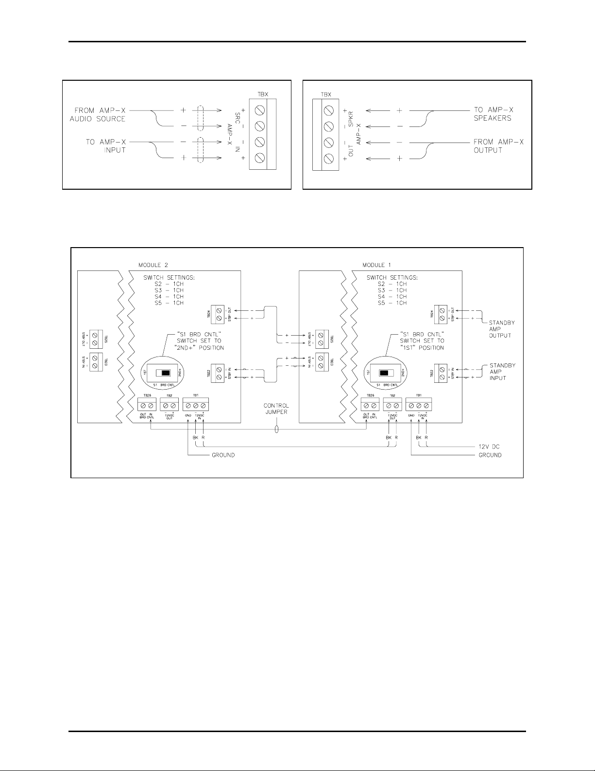
Figure 3. Input Connections
Figure 4. Output Connections
Figure 5. Cascaded modules operated in single channel mode
\\s_eng\gtc proddoc s \st andard iom s - current release\42004 instr. manuals \ 42004-375a. doc
09/05
Page 5

Pub. 42004-375A
Model 12599-001 Hot Standby Amplifier Module Page: 5 of 11
Figure 6. Cascaded mo dules operated i n dual - channel mode
\\s_eng\gtc proddoc s \st andard iom s - current release\42004 instr. manuals \ 42004-375a. doc
09/05
Page 6

Pub. 42004-375A
Model 12599-001 Hot Standby Amplifier Module Page: 6 of 11
Operation
The Model 12599-001 Hot Standby Amplifier Module operates from a 12 V dc power source. With
power applied, all switches properly set and all inputs properly connected, no circuits should be active
until an amplifier fault occurs. The block diagrams below depict typical circuit functions when the
module is operated in either single or dual channel modes.
Figure 7. Block Diagram - Single Channel Operation
\\s_eng\gtc proddoc s \st andard iom s - current release\42004 instr. manuals \ 42004-375a. doc
09/05
Page 7

Pub. 42004-375A
Model 12599-001 Hot Standby Amplifier Module Page: 7 of 11
Figure 8. Block D iagram - Dual-Chan n e l Oper atio n
\\s_eng\gtc proddoc s \st andard iom s - current release\42004 instr. manuals \ 42004-375a. doc
09/05
Page 8

Pub. 42004-375A
Model 12599-001 Hot Standby Amplifier Module Page: 8 of 11
Theory of Operation
The Amp-1 through Amp-6 fault inputs at TB3 on the Model 12599-001 Hot Standby Amplifier Module
provide a single connection point for each amplifier fault output. The OUT (output) terminal provides dc
common to the amplifier’s internal fault circuit and the RET (return) terminal ties to the output side of the
amplifier’s internal fault circuit.
When the connected power amplifier is functioning properly, the amplifier fault output control signal to
the RET terminal must be an active Low (below 6 volts; a dc level at or near zero volts is optimum).
When the a mplif ier’s interna l fault cir c uitry detects a prob lem, s uch as a shorted or overloa ded out put,
excessive temperature, etc., or ac power is removed from the amplifier, the amplifier’s fault output floats
high to a positive (+) polarity. The associated RET input circuit detects this voltage change, and activates
the associated relay group to switch the standby amplifier in place of the faulty amplifier. The circuit will
remain active until the amplifier fault condition remedied.
Priority Switching
The 12599-001 Hot Standby Amplifier Module prioritizes the switching of the standby amplifier for two
reasons, which are:
1. To avoid excessive loading of the standby amplifier in the event of multiple amplifier failures, and
2. To ensure that critical facility areas receive alarm and voice audio broadcasts during emergencies.
The order of priority switching from highest to lowest is Amp-1 to Amp-6 respectively. This means that
Amp-1 has the highest priority and Amp-6 has lowest priority. This prioritization scheme applies if the
board is operated in either 1-channel or 2-channel modes. If cascaded with other modules, module 1 has a
high er pr iorit y than module 2, and modu le 2 has higher p riority tha n modu le 3, et c .
While it is diffic u l t to deter mine which area of a facility is the most c riti c al (as in ite m 2 above) , an
example is a n o f f shore oil platform system with multipl e amplifiers . In this c ase, t he living quarters (LQ )
are usually considered such an area. In this type of system/cabinet design, the LQ amplifier should be
connected to the Amp-1 terminals to ensure that personnel (sleeping in the LQ) will be alerted during
emergencies.
Dry Cont act Output s
The Model 12599-001 Hot Standby Amplifier Module provides six, form “C” dry contact outputs (one
per amplifier circuit), which can be used for triggering either a remote status indicator, or an input at a
supervised system device for visual text display. Each output contact operates in conjunction with its
respective fault detection circuit so that the status of all connected amplifiers can be monitored at all
times, regardless of their priority assignment.
Cascading Modules
The Model 12599-001 Hot Standby Amplifier Module can be operated with a series of other modules in a
cascade. This feature is useful in cabinet/system applications when the following criteria must be met:
• A higher ratio of primary (active) amplifiers to a standby amplifier is needed, or
• In particular, when dual-channel amplifiers are employed.
\\s_eng\gtc proddoc s \st andard iom s - current release\42004 instr. manuals \ 42004-375a. doc
09/05
Page 9

Pub. 42004-375A
Model 12599-001 Hot Standby Amplifier Module Page: 9 of 11
When using the cascade feature, t h e IN/OUT control at T B26 must b e used b et w een modu l es. For the
cas c ade to function properly, connect the OUT terminal of the first module to the IN terminal at the
second module. Do not make any connections to the IN
terminal at the first module. For subsequent
modules in the cascade, this In/Out wiring arrangement must continue across all modules.
In addition to In/Out control across modules, the mode switches S1 through S5 must also be set to the
proper operating position. See the Mode Switches (S1-S5) section below for information on the function
and settings of these switches.
Mode Swi tches (S1 – S 5)
The Model 12599-001 Hot Standby Amplifier Module is equipped with five mode control switches. The
functio n of eac h is swit ch is described below:
S1 Brd Cntl (Board Control) – Since relay sw itching on th is module is prior i tize d, this swit c h
determines if the module is operated as standalone, the fir st of multiple modules, or is operating behi nd
another module. If the module is used standalone, or is the first of multiple modules, the switch must be
set to the 1
path, the switch must be set to the 2
ST position. Howe ver, if the module opera tes b e hind another module in a cascade d control
ND+ position.
S2/S3 Sw’g Cnt l (Switching Control) – Since this module is designed to switch either six single-
channel amplifiers or three dual-channel amplifiers, these two switches must be set to the appropriate
position for the type of amplifier being switched, e.g., 1CH (1-channel) or 2CH (2-channel) resp ect i vel y.
(See the note below.)
When t he switches a re s et to the 1CH position, all six relay circuit groups operate independently via
control from their respective fault input circuits. When the switches are set to the 2CH
position, the
Amp-1/Amp-4 circuits, Amp-2/Amp-5 circuits, and Amp-3/Amp-6 circuits are linked for switching both
channels of the a mplifier simu ltan eousl y.
S4 Input Bus – This switch allows the input signal bus to function across all six relay circuits for six
single-channel amplifiers, or be split for three dual-channel amplifiers. Thus, if switches S2 and S3 are
set to either 1CH or 2CH, this switch must also be set to the same operating mode. See the note below.
S5 Output Bus – This switch allows the output signal bus to function across all six relay circuits for six
single channel amplifiers, or be split for three dual-channel amplifiers. Thus, if switches S2, S3 and S4
are set to either 1CH or 2CH, this switch must also be set to the same operating mode. See the note
below.
NOTE
Switches S2, S3, S4 and S5 must be set to the same operating position. Do NOT operate any of the
switc h es in oppo site positions as this wi ll resu lt in improper op erat ion of t his module .
\\s_eng\gtc proddoc s \st andard iom s - current release\42004 instr. manuals \ 42004-375a. doc
09/05
Page 10

Pub. 42004-375A
Model 12599-001 Hot Standby Amplifier Module Page: 10 of 11
Maintenance
The H ot Standby Ampl ifier Modu le do es not co ntai n any u ser serviceable parts. Do not attempt to make
any repairs to the module.
If the module re quires service, c o ntact your Regional Ser vice Ce nter f or a r et urn authorization number
(RA# ) . The module should be s hipp e d prepaid t o GAI- T ronics with a ret urn authorization numb er and a
purchase order number. If the module is under warranty, repairs or a replacement will be made in
accordance with GAI-Tronics’ warranty policy. Please include a written explanation of all defects to
assist our technicians in their troubleshooting efforts.
Call 800-492-1212 inside the USA or 610-777-1374 outside the USA for help identifying the Regional
Service Center closest to y o u.
Troubl eshooting
Problem Solution
Module is damaged. Do not attempt to repair the module.
Module does not switch to backup
amplifier when any of the primary
amplifiers fail or are powereddown.
Unused circuits are energized.
Relay switching activity can be
heard on the module and output
cont acts are functioning.
But the associated LED does not
illu minate and the primary au dio
lines are not switching to the
standby ( back- up) amplifier .
Amplifier 4 switches when
amplifier 1 fails. Likewise,
amplifier 5 swit ches wh en amplifier
2 fa ils , and amplif ier 6 s wit ches
when amplif ier 3 fails.
Contact GAI-Tronics service for repair or replacement of the
module in accordance with the information provided on page 10.
Check polarity of wiring between fault inputs at the module, and
the fault outputs at each amplifier. If using an amplifier equipped
with a RJ-11 fault output connector, a reversal of the cable leads
should correct the problem.
Also, be sure the amplifier fault outputs are ground (dc common)
ref erenced, and funct ion a s descr i bed on page 8 .
Install a jumper across any/all unused fault inputs, as described
on page 2.
If the module is used standalone or is the first in a cascade, set the
BRD
CNTL switch S1 to the 1ST position, as desc ribed on
page 9.
Be sure switches S2 through S5 are set to the 1CH position when
using single-channel (monaural) amplifiers, as described on
page 9.
Both channels of the amplifiers are
not switching si multaneous ly whe n
Be sure switches S2 through S5 are set to the 2CH position when
usin g dual-cha nnel (stereo) ampl ifier s, as descri bed on pa g e 9 .
faulted.
\\s_eng\gtc proddoc s \st andard iom s - current release\42004 instr. manuals \ 42004-375a. doc
09/05
Page 11

Pub. 42004-375A
Model 12599-001 Hot Standby Amplifier Module Page: 11 of 11
Problem Solution
Amplifiers on the second
(cas ca d ed) mo dul e op er a te
independent of the priority control
scheme described on page 8.
In a cascade arrangement, switch S1 must be set to the 1ST
position at the first module, and the 2ND+ position at the second
modu le, and all s u bsequent module s, a s descr ibed on page 9 .
Also, be sure wiring at the IN/OUT
CNTL terminals at TB26
conforms to Figure 5 or Figure 6 on pages 4 or 5, respectively.
After performing all wiring checks,
tr ouble-shooting, etc . as describe d
Contact GAI-Tronics service for repair or replacement of the
module in accordance with the information provided on page 10.
in this section, the module still does
not function properly.
Specification s
Electrical
Power requirements............................................................................... 9.5 to 14 V dc (12 V dc nominal)
Current draw .............................................................................................. 300 mA maximum @ 12 V dc
Number of amplifier inputs.................................................................. 6-single channel or 3-dual channel
Fault input terminal voltage ........................................................................................... 6 V dc (nominal)
Fault input trigger voltages........................................................... 6.01 V dc (active); 5.99 V dc (inactive)
Fault input circuit current ..............................................................................................................1.2 mA
Number of fault output contacts.................................... 6 (single channel mode) or 3 (dual-channel mode)
Fault output contact type ................................................................................................. Single form “C”
Fault output contact rating................................................................................. 2 A maximum @ 30 V dc
Amplifi er Audio S witchin g
Amplifier type........................................................................................................ Single or dual-cha nnel
Audio input levels (typical per circuit).................................. 600 ohm @ .775 Vrms (0 dBm) to 1.5 Vrms
Amplifier output power (maximum per circuit)............................................. 720 watts (100% duty cycle)
Speaker load switching.................................................................................. Standard 4, 8 or 16-ohms, or
25 V, 70 V or 100 V constant voltage lines
Terminations
Type..................................................................................................... Modular (plug-in) terminal blocks
Minimum conductor size............................................................................................ 28 AWG (0.5 mm
Maximum conductor size............................................................................................ 12 AWG (3.0 mm
2
2
Mechanical
Module dimensions .................................... 12.00 L × 4.00 W × 1.25 H inches (304.8 × 101.6 × 31.7 mm)
Module weight................................................................................................................. 1.1 lbs . (0.5 kg)
Enviro nmental
Temperature range (operating/storage)............................................................. 32° to 140° F (0° to 60° C)
Humidity ....................................................................................... 85% non-condensing relative humidity
)
)
\\s_eng\gtc proddoc s \st andard iom s - current release\42004 instr. manuals \ 42004-375a. doc
09/05
 Loading...