

Page 1
Pub. 42004-400A
GAI-TRONICS® CORPORATION
A HUBBELL COMPANY
Model 12598-001
Redundant 12 V DC Module
Confidentiality Notice
This manua l is provide d sole ly as an operatio nal, installation, and ma inte nance guide and conta ins
sensitive business and t e chnical informatio n tha t is confidentia l and pr opri et ary to GAI- Tronics.
GAI-Tronics retains all intellectual property and other rights in or to the information contained herein,
and such information may only be used in connection with the operation of your GAI-Tronics product or
system. This manu al may not be dis clos e d in any form, in whole or in pa rt, direct ly or i ndir ectly, to a ny
third pa r ty.
General Information
The Model 12598-001 Redundant DC Module is designed to accept the outputs of two 12 V dc power
supplies while providing a single dc output. This module will typically be used in custom products,
name ly ADVANCE c abinet s requiring redundant ci rcui ts to me et various agency requ ireme n ts.
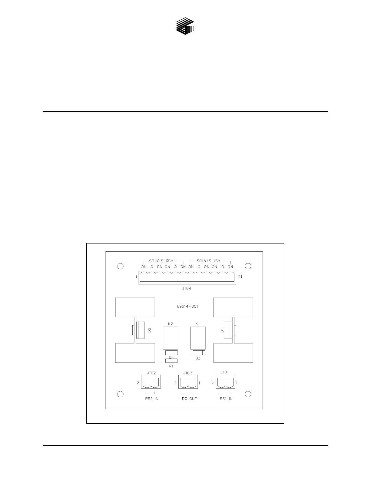
Figure 1. Model 12598-001 Redundant 12 V DC Module
GAI-Tronics Corporation P.O. Box 1060, Readi ng, PA 19607-1060 USA
610-777-1374 800-492-1212 Fax: 610-796-5954
ISIT WWW.GAI-TRONICS.COM FOR PRODUCT LITERATURE AND MANUALS
V
Page 2

Pub. 42004-400A
Model 12598-001 Redundant 12V DC Module Page: 2 of 5
Hardware Configuration
The Model 12598-001 Redundant 12 V DC Module consists of a single-sided printed circuit board
measuring 4 L × 4 W × 1.5 H inches (102 × 102 × 38.1 mm). It is equipped with two 15A rated diodes
each mounted t o a heat sink, two s mall DPDT relays to provide dry co ntact sta tus outpu ts for each po w er
supply, and four modular (plug-in type) terminal blocks. All components on the board are through-hole.
Installation
CAUTION
When insta lling or rep lacing this module, be s ure to disconnect power for
safety.
The Model 12598-001 Redundant 12 V DC Module is designed for chassis mounting or on 4-inch Snap
Trak®. When inserting the module in SnapTrak®, exer cise care when pressin g the module edges int o the
SnapTrak
Once installed in the SnapTrak
®
to avoid damage to th e module’s print e d circuit boar d and components .
®
, be sure the module edges are secured in the channels so that the module
does not dislodge during transport or operation if subjected to vibration. Also, if this module is used with
other modules in the SnapTrak
®
, be sure to leave spacing between modules to facilitate wiring at any
edge-mounted terminal blocks.
Terminations
The Model 12598-001 Redundant 12 V DC Module is equipped with modular (plug-in type) terminal
blocks, which simplify external wire connections during installation, and provide quick disconnect if
repla cement is ever required.
The following is a breakdown of each terminal block and its function(s):
TB1 – is the 12 V dc power input from Power Supply 1 (PS1) to the module.
TB2 – is the 12 V dc power input from Power Supply 2 (PS2) to the module.
TB3 – is the 12 V dc power output from the module to the load.
TB4 – are dry output contacts for the PS1 and PS2 faults respectively. Each connected power supply has
two sets of contacts, which are a Form “C” type. The maximum switching capacity for each contact set is
30 V dc @ 1 amp, and can be used for triggering a remote status indicator or a supervised input at a
system device for visual text display.
f:\standard ioms - current releas e\ 42004 ins t r. manuals\42004-400a.doc
07/07
Page 3

Pub. 42004-400A
Model 12598-001 Redundant 12V DC Module Page: 3 of 5
Operation
After successful installation and testing, the Model 12598-001 Module requires no operator intervention.
Functional O peration
The Model 12598-001 Redundant 12 V DC Module operates with two 12 V dc power supplies. When 12
V dc power is applied to the PS1
active. Output voltage at the DC
to a voltag e drop of app rox. 0.6 V t o 0.9 V depending on the load current throu gh CR 1 and CR2. Thus,
as load current increases through the diodes, the voltage drop across each diode increases toward the
maxi mum val u e of 0 . 9 V.
Als o, since CR1 or CR2 have a sli ghtly differ ent voltage drops ( or tu rn-on thr eshol ds), e i ther of th e
connected power supplies (at PS1
IN and PS2 IN termi nals of the module, rela ys K1 and K2 be come
OUT terminals will be approximately 11.4 V to 11.1 V dc, which is due
IN or PS2 IN) may initially supply power to load.
Maintenance
The Model 12598-001 Redundant 12 V DC Module does not contain any user serviceable parts. Do not
attempt to make any repairs to the module.
If the module re quires service, c o ntact your Regional Ser vice Ce nter f or a r et urn authorization number
(RA# ) . The module should be s hipp e d prepaid t o GAI- T ronics with a ret urn authorization numb er and a
purchase order number. If the module is under warranty, repairs or a replacement will be made in
accordance with GAI-Tronics’ warranty policy. Please include a written explanation of all defects to
assist our technicians in their troubleshooting efforts.
Call 800-492-1212 inside the USA or 610-777-1374 outside the USA for help identifying the Regional
Service Center closest to y o u.
f:\standard ioms - current releas e\ 42004 ins t r. manuals\42004-400a.doc
07/07
Page 4

Pub. 42004-400A
Model 12598-001 Redundant 12V DC Module Page: 4 of 5
Troubl eshooting
Problem Solution
Module is damaged. Do not attempt to repair the module.
Contact GAI-Tronics service for repair or replacement of the
module in accordance with the information provided on this page.
Voltage is applied to both inputs,
but voltage is not present at the
output terminals.
All connectio ns a n d conn ect or s are
properly made, but still no output
voltage.
Relay status contac t markin gs are
incorrect when module is not
powered.
After performing all wiring checks,
tr ouble-shooting, etc . as describe d
in this section, the module still does
not function properly.
Veri fy plug-in con nectors at JTB1, JTB 2 and JTB3 are properl y
inserted.
Verify wiring at each connector has proper polarity.
The r e lay st atus contact ma rkings are based on the modu le being
actively powered (i.e., in an energized state).
Contact GAI-Tronics service for repair or replacement of the
module in accordance with the information provided on this page.
f:\standard ioms - current releas e\ 42004 ins t r. manuals\42004-400a.doc
07/07
Page 5

Pub. 42004-400A
Model 12598-001 Redundant 12V DC Module Page: 5 of 5
Specification s
Electrical
Power requirements................................................................................... 10–14 V dc (12 V dc nominal)
Current handling capacity................................................................................ 10 A maximum @ 12 V dc
Voltage drop from input(s) to output.................................................. Approximately 0.6 V dc to 0.9 V dc
Number of inputs.....................................................................................................................................2
Number of outputs................................................................................................................................... 1
Number of fault outputs............................................................................................ Four (Two per input)
Fault output type..................................................................................................... Form “C” dry contact
Fault output contact rating................................................................................. 1 A maximum @ 30 V dc
Terminations
Type..................................................................................................... Modular (plug-in) terminal blocks
Minimum conductor size...................................................................................... No. 28 AWG (0.5 mm
Maximum conductor size...................................................................................... No. 12 AWG (3.0 mm
2
2
)
)
Mechanical
Module dimensions ...................................... 4.00 L × 4.00 W × 1.50 H inches (101.6 × 101.6 × 38.1 mm)
Module weight............................................................................................................. 0.32 lbs. (0.14 kg)
Enviro nmental
Temperature range – 100% load (operating ambient)......................................... 32° to 77° F (0° to 25° C)
Temperature range – 50% load (operating ambient)......................................... 32° to 115° F (0° to 46° C)
Temperature range – 25% load (operating ambient)......................................... 32° to 140° F (0° to 60° C)
Temperature range (storage)............................................................................ 32° to 140° F (0 ° to 60° C)
Humidity ....................................................................................... 85% non-condensing relative humidity
f:\standard ioms - current releas e\ 42004 ins t r. manuals\42004-400a.doc
07/07
Page 6

Warranty
Equipment. GAI-Tronics warrants for a period of one (1) year from the date of shipment, that any
GAI-Tronics equipment supplied hereunder shall be free of defects in material and workmanship, shall
comply with the then-current product specifications and product literature, and if applicable, shall be fit
for the purpose specified in the agreed-upon quotation or proposal document. If (a) Seller’s goods prove
to be defective in workmanship and/or material under normal and proper usage, or unfit for the purpose
specified and agreed upon, and (b) Buyer’s claim is made within the warranty period set forth above,
Buyer may return such goods to GAI-Tronics’ nearest depot repair facility, freight prepaid, at which time
they will be repaired or replaced, at Seller’s option, without charge to Buyer. Repair or replacement shall
be Buyer’s sole and exclusive remedy. The warranty period on any repaired or replacement equipment
shall be the greater of the ninety (90) day repair warranty or one (1) year from the date the original
equipment was shipped. In no event shall GAI-Tronics warranty obligations with respect to equipment
exceed 100% of the total cost of the equipment supplied hereunder. Buyer may also be entitled to the
manufacturer’s warranty on any third-party goods supplied by GAI-Tronics hereunder. The applicability
of any such third-party warranty will be determined by GAI-Tronics.
Services. Any services GAI-Tronics provides hereunder, whether directly or through subcontractors,
shall be performed in accordance with the standard of care with which such services are normally
provided in the industry. If the services fail to meet the applicable industry standard, GAI-Tronics will
re-perform such services at no cost to buyer to correct said deficiency to Company's satisfaction provided
any and all issues are identified prior to the demobilization of the Contractor’s personnel from the work
site. Re-performance of services shall be Buyer’s sole and exclusive remedy, and in no event shall GAITronics warranty obligations with respect to services exceed 100% of the total cost of the services
provided hereunder.
Warranty Periods. Every claim by Buyer alleging a defect in the goods and/or services provided
hereunder shall be deemed waived unless such claim is made in writing within the applicable warranty
periods as set forth above. Provided, however, that if the defect complained of is latent and not
discoverable within the above warranty periods, every claim arising on account of such latent defect shall
be deemed waived unless it is made in writing within a reasonable time after such latent defect is or
should have been discovered by Buyer.
Limitations / Exclusions. The warranties herein shall not apply to, and GAI-Tronics shall not be
responsible for, any damage to the goods or failure of the services supplied hereunder, to the extent
caused by Buyer’s neglect, failure to follow operational and maintenance procedures provided with the
equipment, or the use of technicians not specifically authorized by GAI-Tronics to maintain or service the
equipment. THE WARRANTIES AND REMEDIES CONTAINED HEREIN ARE IN LIEU OF AND
EXCLUDE ALL OTHER WARRANTIES AND REMEDIES, WHETHER EXPRESS OR IMPLIED BY
OPERATION OF LAW OR OTHERWISE, INCLUDING ANY WARRANTIES OF
MERCHANTABILITY OR FITNESS FOR A PARTICULAR PURPOSE.
Return Policy
If the equipment requires service, contact your Regional Service Center for a return authorization number
(RA#). Equipment should be shipped prepaid to GAI-Tronics with a return authorization number and a
purchase order number. If the equipment is under warranty, repairs or a replacement will be made in
accordance with the warranty policy set forth above. Please include a written explanation of all defects to
assist our technicians in their troubleshooting efforts.
Call 800-492-1212 (inside the USA) or 610-777-1374 (outside the USA) for help identifying the
Regional Service Center closest to you.
(Rev. 10/06)
 Loading...