

Page 1
Pub. 42004-475A
GAI-TRONICS® CORPORATION
A HUBBELL COMPANY
Model 12594-101
Redundant AZI Switching Module
Confidential ity Notice
This manual is provided solely as an operational, installation, and maintenance guide and contains
sensitive business and technical information that is confidential and proprietary to GAI-Tronics.
GAI-Tronics retains all intellectual property and other rights in or to the information contained herein,
and such information may only be used in connection with the operation of your GAI-Tronics product or
system. This manual may not be disclosed in any form, in whole or in part, directly or indirectly, to any
third party.
General Information
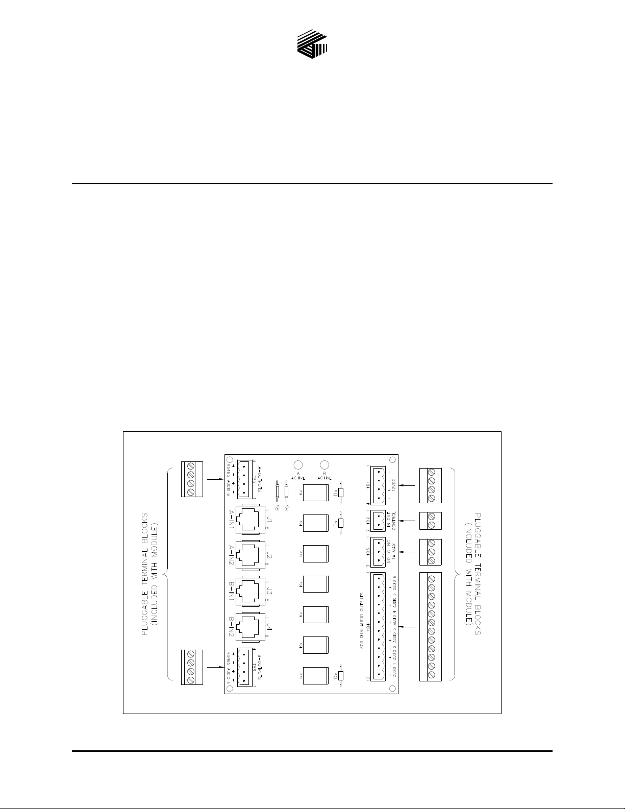
The Model 12594-101 Redundant AZI Switching Module is designed to provide connection for a primary
and a secondary AZI card when redundant circuits are required in GAI-Tronics ADVANCE cabinets or
other audio switching applications. The module controls audio line switching from the AZI cards to
amplifier inputs. Each module is capable of switching six audio lines. The switching action is controlled
by an external contact closure.
Figure 1. Model 12594-101 Redundant AZI Switching Module
GAI-Tronics Corporation 400 E. Wyomissing Ave. Mohnton, PA 19540 USA
610-777-1374 800-492-1212 Fax: 610-796-5954
V
ISIT WWW.GAI-TRONICS.COM FOR PRODUCT LITERATURE AND MANUALS
Page 2

Pub. 42004-475A
Model 12594-101 Redundant AZI Switching Module Page 2 of 5
Installation
CAUTION
When installing or replacing this module, be sure power is not applied to
avoid damage to the module circuits.
The Model 12594-101 Redundant AZI Switching Module is designed for mounting in 4-inch Snap Trak
When inserting the module in SnapTrak
, exercise care when pressing on the module edges to avoid
damage to the module’s printed circuit board and components.
Once installed in the SnapTrak
, be sure the module edges are secured in the channels so that the module
does not dislodge during transport or operation if subjected to vibration. Also, if this module is used with
other modules in the SnapTrak
, be sure to leave spacing between modules to facilitate wiring at any
edge-mounted terminal blocks.
Terminations
The following is a description of the available terminations:
J1 – is the first primary AZI card connection; a standard straight through Cat5E cable is required.
J2 – is the second primary AZI card connection; a standard straight through Cat5E cable is required.
J3 – is the first secondary AZI card connection; a standard straight through Cat5E cable is required.
J4 – is the second secondary AZI card connection; a standard straight through Cat5E cable is required.
.
TB1 – is the 12 V dc power input to the module.
TB2 – is the control input to the module to activate the relays to switch between primary and secondary
AZI cards.
TB3 – is the Form “C” dry contact output, which can be used to activate other devices or for remote
status indication. The maximum switching capacity for the contact set is 30 V dc @ 1 amp.
TB4 – is for the six switched, audio outputs.
TB5 – is the primary RS-485 data connection and an auxiliary audio output connection from the
AUDIO-6 output of the primary AZI card that can be used to supply audio signals to other devices, if
needed.
TB6 – is the secondary RS-485 data connection and an auxiliary audio output connection from the
AUDIO-6 output of the secondary AZI card that can be used to supply audio signals to other devices, if
needed.
f:\standard ioms - current release\42004 instr. man uals\42004-475a.doc
04/13
Page 3

Pub. 42004-475A
Model 12594-101 Redundant AZI Switching Module Page 3 of 5
The following is a summary of each connector and terminal block function(s):
J1 – Pri. AZI Card "A" (RJ45 jack) J2 – Pri. AZI Card "B" (RJ45 jack)
Pin No. Function Pin No. Function
1 & 2 Audio Line #1 1 & 2 Audio Line #5
3 & 6 Audio Line #2 3 & 6 Audio Line #6
4 & 5 Audio Line #3 4 & 5 RS-485 data
7 & 8 Audio Line #4 7 & 8 No connection
J3 – Sec. AZI Car d "A" (RJ45 jack ) J4 – Sec. AZI Car d "B" (RJ45 jack )
Pin No. Function Pin No. Function
1 & 2 Audio Line #1 1 & 2 Audio Line #5
3 & 6 Audio Line #2 3 & 6 Audio Line #6
4 & 5 Audio Line #3 4 & 5 RS-485 data
7 & 8 Audio Line #4 7 & 8 No connection
TB1 – 12 V dc Power I nput
Terminal No. Function
TB2 - 12 V dc Power O utput
Terminal No. Function
1 & 2 12 V (−) 1 & 2 Control Line (active low)
3 & 4 12 V (+)
TB3 – Relay Contact Output
Terminal No. Function
TB4 – Audio Outputs
Terminal No. Function
1 Normally closed 1 & 2 Audio Line #6
2 Common 3 & 4 Audio Line #5
3 Normally open 5 & 6 Audio Line #4
7 & 8 Audio Line #3
9 & 10 Audio Line #2
11 & 12 Audio Line #1
f:\standard ioms - current release\42004 instr. man uals\42004-475a.doc
04/13
Page 4

Pub. 42004-475A
Model 12594-101 Redundant AZI Switching Module Page 4 of 5
TB5 – Pri. RS-485 Data and
Audio Output #6
Terminal No. Function
1 Audio Line 6 (−) 1 Audio Line 6 (−)
2 Audio Line 6 (+) 2 Audio Line 6 (+)
3 RS-485 data (−) 3 RS-485 data (−)
4 RS-485 data (+) 4 RS-485 data (+)
TB6 – Sec. RS-485 Data and
Audio Output #6
Terminal No. Function
Operation
The module has essentially two modes of operation, normal and fault. Each mode is described in detail
below.
TB5 and TB6 are not affected by the module’s switching action. They are simply pass-through terminals
for the RS-485 data lines and audio line #6 from the AZI cards. TB5 connects to the Primary AZI card
(J2) and TB6 connects to the Secondary AZI card (J4).
Normal Condition
Connecting the Control Input (TB2) to dc ground will energize all relays on the module. LED1 (AActive) will illuminate to indicate the Primary system is active. The Primary AZI card’s audio (J1 & J2)
is connected to the audio output terminals (TB4). The Secondary AZI card’s audio (J3 & J4) is
disconnected from the audio output terminals (TB4).
Fault Co ndition
The dc ground is removed from TB2 during a fault condition. LED2 (B-Active) illuminates to indicate
the Secondary system is active. All of the relays are de-energized. Relay K1 contacts are wired to TB3
and will change state for the duration of the fault condition. Relays K2–K7 switch the Secondary AZI
card’s audio (J3 & J4) to the audio output terminals (TB4). The Primary AZI card’s audio (J1 & J2) is
disconnected from the audio output terminals (TB4).
Maintenance
If the module requires service, contact your Regional Service Center for a return authorization number
(RA#). The module should be shipped prepaid to GAI-Tronics with a return authorization number and a
purchase order number. If the module is under warranty, repairs or a replacement will be made in
accordance with GAI-Tronics’ warranty policy. Please include a written explanation of all defects to
assist our technicians in their troubleshooting efforts.
Call 800-492-1212 inside the USA or 610-777-1374 outside the USA for help identifying the Regional
Service Center closest to you.
f:\standard ioms - current release\42004 instr. man uals\42004-475a.doc
04/13
Page 5

Pub. 42004-475A
Model 12594-101 Redundant AZI Switching Module Page 5 of 5
Troubleshooting
Problem Solution
No audio from output terminals
Verify Cat5E cables at J1, J2, J3 and J4 on the module are
properly connected to AZI cards at designated card racks.
Verify amplifiers are connected to the correct outputs along
with proper polarity at TB4.
Verify primary and secondary MCU cards contain correct
software configurations to output audio at designated AZI
amplifier outputs.
Module LEDs do not illuminate
and relays do not switch when
input control is provided.
Module still does not function after
all checks described in this section.
Verify 12 V dc power is applied to the module.
Verify 12 V dc (−) is being switched to the C
ONTROL input
at TB2.
Contact GAI-Tronics service for repair or replacement of the
module in accordance with the information provided on this page.
Specification s
Electrical
Power requirements ................................................................... 10–14 V dc (12 V dc @ 91.5 mA nominal)
Number of control inputs ......................................................................................................................... One
Number of fault outputs ........................................................................................................................... One
Fault output type .......................................................................................................... Form “C” dry contact
Fault output contact rating .................................................................................... 1 A maximum @ 30 V dc
Connections
RJ45 jacks ............................................................................................................................................... Four
Modular (plug-in) terminal blocks ............................................................................................................ Six
Minimum terminal block conductor size .................................................................. No. 28 AWG (0.5 mm
Maximum terminal block conductor size .................................................................. No. 12 AWG (3.0 mm
2
2
Mechanical
Module dimensions ........................................ 5.50 L 4.00 W 1.44 H inches (139.7 101.6 36.6 mm)
Module weight .................................................................................................................. 0.38 lbs. (0.17 kg)
Environmental
Temperature range (operating/storage) ..................................................... −4 F to 158 F (−20 C to 70 C)
Humidity .......................................................................................... 85% non-condensing relative humidity
f:\standard ioms - current release\42004 instr. man uals\42004-475a.doc
04/13
)
)
Page 6

Warranty
Equipment. GAI-Tronics warrants for a period of one (1) year from the date of shipment, that any
GAI-Tronics equipment supplied hereunder shall be free of defects in material and workmanship, shall
comply with the then-current product specifications and product literature, and if applicable, shall be fit
for the purpose specified in the agreed upon quotation or proposal document. If (a) Seller’s goods prove
to be defective in workmanship and/or material under normal and proper usage, or unfit for the purpose
specified and agreed upon, and (b) Buyer’s claim is made within the warranty period set forth above,
Buyer may return such goods to GAI-Tronics nearest depot repair facility, freight prepaid, at which time
they will be repaired or replaced, at Seller’s option, without charge to Buyer. Repair or replacement shall
be Buyer’s sole and exclusive remedy. The warranty period on any repaired or replacement equipment
shall be the greater of the ninety (90) day repair warranty or one (1) year from the date the original
equipment was shipped. In no event shall GAI-Tronics warranty obligations with respect to equipment
exceed 100% of the total cost of the equipment supplied hereunder. Buyer may also be entitled to the
manufacturer’s warranty on any third-party goods supplied by GAI-Tronics hereunder. The applicability
of any such third-party warranty will be determined by GAI-Tronics.
Services. Any services GAI-Tronics provides hereunder, whether directly or through subcontractors,
shall be performed in accordance with the standard of care with which such services are normally
provided in the industry. If the services fail to meet the applicable industry standard, GAI-Tronics will reperform such services at no cost to buyer to correct said deficiency to Company's satisfaction provided
any and all issues are identified prior to the demobilization of the Contractor's personnel from the work
site. Re-performance of services shall be Buyer's sole and exclusive remedy, and in no event shall GAITronics warranty obligations with respect to services exceed 100% of the total cost of the services
provided hereunder.
Warranty Periods. Every claim by Buyer alleging a defect in the goods and/or services provided
hereunder shall be deemed waived unless such claim is made in writing within the applicable warranty
periods as set forth above. Provided, however, that if the defect complained of is latent and not
discoverable within the above warranty periods, every claim arising on account of such latent defect shall
be deemed waived unless it is made in writing within a reasonable time after such latent defect is or
should have been discovered by Buyer.
Limitations / Exclusions. The warranties herein shall not apply to, and GAI-Tronics shall not be
responsible for, any damage to the goods or failure of the services supplied hereunder, to the extent
caused by Buyer’s neglect, failure to follow operational and maintenance procedures provided with the
equipment, or the use of technicians not specifically authorized by GAI-Tronics to maintain or service the
equipment. THE WARRANTIES AND REMEDIES CONTAINED HEREIN ARE IN LIEU OF AND
EXCLUDE ALL OTHER WARRANTIES AND REMEDIES, WHETHER EXPRESS OR IMPLIED BY
OPERATION OF LAW OR OTHERWISE, INCLUDING ANY WARRANTIES OF
MERCHANTABILITY OR FITNESS FOR A PARTICULAR PURPOSE.
Return Policy
If the equipment requires service, contact your Regional Service Center for a return authorization number
(RA#). Equipment should be shipped prepaid to GAI-Tronics with a return authorization number and a
purchase order number. If the equipment is under warranty, repairs or a replacement will be made in
accordance with the warranty policy set forth above. Please include a written explanation of all defects to
assist our technicians in their troubleshooting efforts.
Call 800-492-1212 (inside the USA) or 610-777-1374 (outside the USA) for help identifying the
Regional Service Center closest to you.
(Rev. 10/06)
 Loading...