

Page 1
Pub. 42004-406A
GAI-TRONICS® CORPORATION
A HUBBELL COMPANY
Model 12594-001
Redundant AZI Switching Module
Confidentiality Notice
This manua l is provide d sole ly as an operatio nal, installation, and ma inte nance guide and conta ins
sensitive business and t e chnical informatio n tha t is confidentia l and pr opri et ary to GAI- Tronics.
GAI-Tronics retains all intellectual property and other rights in or to the information contained herein,
and such information may only be used in connection with the operation of your GAI-Tronics product or
system. This manu al may not be dis clos e d in any form, in whole or in pa rt, direct ly or i ndir ectly, to a ny
third pa r ty.
General Information
The Model 12594-001 Redundant AZI Switching Module is designed to provide connection for a primary
and a secondary AZI card when redundant circuits are required in GAI-Tronics ADVANCE cabinets or
oth er au dio swit chin g applications. The module controls audi o line s w itch ing from the AZI cards t o
amplifier inputs. Each module is capable of switching six audio lines. The switching action is controlled
by an external contact closure.
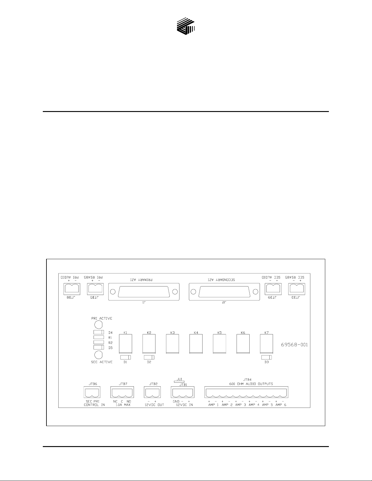
Figure 1. Model 12594-001 Redundant AZI Switching Module
GAI-Tronics Corporation P.O. Box 1060, Readi ng, PA 19607-1060 USA
610-777-1374 800-492-1212 Fax: 610-796-5954
ISIT WWW.GAI-TRONICS.COM FOR PRODUCT LITERATURE AND MANUALS
V
Page 2

Pub. 42004-406A
Model 12594-001 Redundant A ZI Switching Module Page: 2 of 7
Installation
CAUTION
When instal ling o r replacing this mod ul e, be sure power is not app l ied to
avoid damage to the module circuits.
The Model 12594-001 Redundant AZI Switching Module is designed for mounting in 4-inch Snap Trak
When inserting the module in SnapTrak
®
, exercise care when pressing on the module edges to avoid
®
dama ge to the module’s pr inted circuit board and compon e nts.
Once installed in the SnapTrak
®
, be sure the module edges are secured in the channels so that the module
does not dislodge during transport or operation if subjected to vibration. Also, if this module is used with
other modules in the SnapTrak
®
, be sure to leave spacing between modules to facilitate wiring at any
edge-mounted terminal blocks.
Terminations
The following is a description of the available terminations:
J1 – is the primary AZI card connection; a cable with a 25-pin “D-Sub” connector is required.
J2 – is the secondary AZI card connection; a cable with a 25-pin “D-Sub” connector is required.
JTB1 – is the 12 V dc power input to the module.
JTB2 – is a feed-through 12 V dc power output to other modules.
JTB3 – is the secondary RS-485 data connection.
.
JTB4 – is for the six switched, audio outputs.
JTB5 – is the primary RS-485 data connection.
JTB6 – are the control inputs to the module to activate the relays to switch between primary and
secondary AZI cards when a fault occur s . Activation at either inpu t requires dc (-) contro l.
JTB7 – is the Form “ C” dry c onta c t out put, which can b e u sed t o activat e other devices or for r e mote
status indication. The maximum switching capacity for the contact set is 30 V dc @ 1 amp.
JTB8 – is an au xiliary audio outp ut connection from the AMP-6 output of the primary AZ I card that ca n
be used to supply audio signals to other devices, if needed.
JTB9 – is an au xiliary audio outp ut connection from the AMP-6 output of the secondary AZI card that
can be used to supply audio signals to other devices, if needed.
\\s_eng\gtc proddoc s \st andard iom s - current release\42004 instr. manuals \ 42004-406a. doc
04/08
Page 3
Pub. 42004-406A
Model 12594-001 Redundant A ZI Switching Module Page: 3 of 7
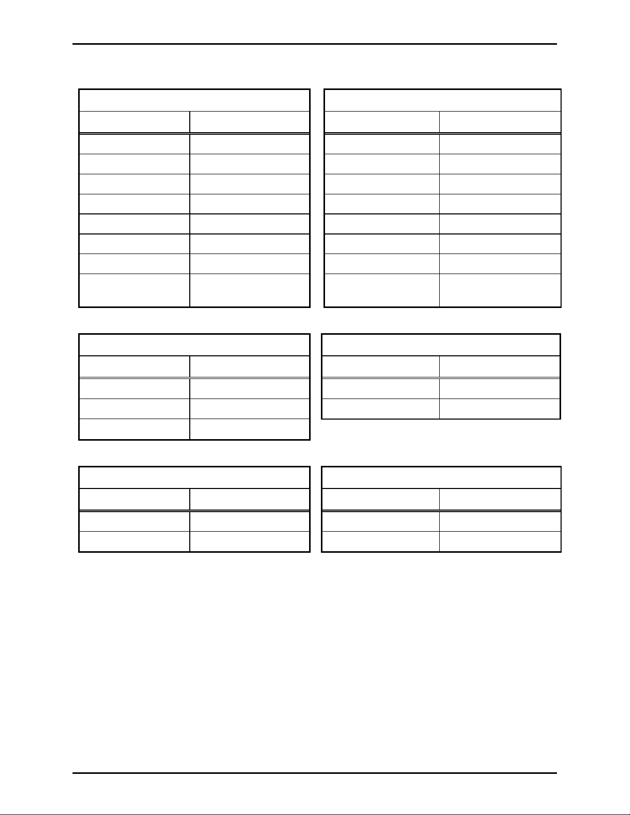
The f ollow ing is a summa ry of each co nnector and ter m inal bloc k f unct ion(s ):
J1 – Primary AZI Card (25-pin D-Sub) J2 – Secondary AZI Card (25-pin D-Sub)
Pin No. Function Pin No. Function
1 & 14 RS-485 Data 1 & 14 RS-485 Data
5 & 18 Audio line #1 5 & 18 Audio line #1
6 & 19 Audio line #2 6 & 19 Audio line #2
7 & 20 Audio line #2 7 & 20 Audio line #2
8 & 21 Audio line #4 8 & 21 Audio line #4
9 & 22 Audio line #5 9 & 22 Audio line #5
10 & 23 Audio line #6 10 & 23 Audio line #6
2-4, 11-13, 15-17,
24-25
Spare – No connection
2-4, 11-13, 15-17,
24-25
Spare – No connection
JTB1 – 12 V dc Power Input JTB2 - 12 V dc Power Output
Terminal No. Function Terminal No. Function
1 12 V (+) 1 12 V (+)
2 12 V (-) 2 12 V (-)
3 GND
JTB3 – Secondary RS-485 data line JTB5 - Primary RS-485 data line
Terminal No. Function Terminal No. Function
1 Data (-) 1 Data (+)
2 Data (+) 2 Data (-)
\\s_eng\gtc proddoc s \st andard iom s - current release\42004 instr. manuals \ 42004-406a. doc
04/08
Page 4

Pub. 42004-406A
Model 12594-001 Redundant A ZI Switching Module Page: 4 of 7
JTB4 – Audio Outputs
Terminal No. Function
JTB6 – Switching Control Inputs
Terminal No. Function
1 & 2 Audio Line #6 1 Primary Control Line
3 & 4 Audio Line #5 2 Secondary Control Line
5 & 6 Audio Line #4
7 & 8 Audio Line #3
9 & 10 Audio Line #2
JTB7 – Rela y Con ta c t Ou tpu t
Terminal No. Function
11 & 12 Audio Line #1 1 Normally Open
2 Common
3 Normally Closed
JTB8 – Primary Audio Output #6
Terminal No. Function
JTB9 – Secondary Audio Output #6
Terminal No. Function
1 Audio (+) 1 Audio (-)
2 Audi o (-) 2 Audio (+)
\\s_eng\gtc proddoc s \st andard iom s - current release\42004 instr. manuals \ 42004-406a. doc
04/08
Page 5

Pub. 42004-406A
Model 12594-001 Redundant A ZI Switching Module Page: 5 of 7
Operation
The module has essentially two modes of operation, normal and fault. Each mode is described in detail
below.
Data line terminals JBT3 and JBT5 are not affected by the module’s switching action. They are simply
pass-through terminals for the RS-485 data lines from the AZI card connectors. JTB3 connects to the
Secondar y AZI car d (J2 ) and JTB5 connects to th e Pr imary AZI ca rd (J1).
Audio line terminals JBT8 and JBT9 are not affected by the boards switching action. They are simply
pass-through terminals for the audio line #6 from the AZI card connectors. JTB8 connects to the Primary
AZI card (J1) and JTB9 connects to the Sec o ndar y AZI card (J2).
Normal Co ndition
All relays on this module are de-energized. The Primary AZI card’s audio (J1) is connected to audio
output terminals (JTB4). The Secondary AZI card’s audio (J2) is disconnected from the audio output
terminals (JTB4).
Fault C onditio n
A fault condition is signaled by connecting either terminal of JBT6 to 12 V dc (-). LED1 (Pri-Active) or
LED2 (Sec-Active) illuminates to indicate the active input. In an ADVANCE system application, these
inputs are active if a primary MCU or primary AMI fault occurs. The control signal input is supplied by
an external relay contact.
When activated, relays K1–K7 are energized. Relay K1 contacts are wired to JBT7 and will change state
for the duration of the active condition. Relays K2–K7 switch the Secondary AZI card’s audio (J2) to the
audio output terminals (JTB4). The Primary AZI card’s audio (J1) is disconnected from the audio output
terminals (JTB4).
\\s_eng\gtc proddoc s \st andard iom s - current release\42004 instr. manuals \ 42004-406a. doc
04/08
Page 6

Pub. 42004-406A
Model 12594-001 Redundant A ZI Switching Module Page: 6 of 7
Maintenance
If the module re quires service, c o ntact your Regional Ser vice Ce nter f or a r et urn authorization number
(RA# ) . The module should be s hipp e d prepaid t o GAI- T ronics with a ret urn authorization numb er and a
purchase order number. If the module is under warranty, repairs or a replacement will be made in
accordance with GAI-Tronics’ warranty policy. Please include a written explanation of all defects to
assist our technicians in their troubleshooting efforts.
Call 800-492-1212 inside the USA or 610-777-1374 outside the USA for help identifying the Regional
Service Center closest to y o u.
Troubl eshooting
Problem Solution
No au dio fr om output terminals
Module LEDs do not illuminate
and r e lays do not s witch when
input control is provided.
Module still does not function after
all checks described in this section.
• Verify ribbon cables at J1 and J2 on the module are properly
connect ed to AZI ca rds at designat ed card racks.
• Verify amplifiers are connected to the correct outputs along
with proper polarity at JTB4.
• Verify primary and secondary MC U c ard s cont ain co rre c t
software con f igur atio ns to ou tput au dio at desig nate d A ZI
amplifier outputs.
• Verify 12 V dc power is applied to the module.
• Verify 12 V dc (-) is being switched to the PRI
and/or SEC
inputs at JTB6.
Contact GAI-Tronics service for repair or replacement of the
module in accordance with the information provided on this page.
\\s_eng\gtc proddoc s \st andard iom s - current release\42004 instr. manuals \ 42004-406a. doc
04/08
Page 7

Pub. 42004-406A
Model 12594-001 Redundant A ZI Switching Module Page: 7 of 7
Specification s
Electrical
Power requirements................................................................. 10–14 V dc (12 V dc @ 91.5 mA nominal)
Number of control inputs ........................................................................................................................ 2
Number of fault outputs.......................................................................................................................... 1
Fault output type..................................................................................................... Form “C” dry conta c t
Fault output contact rating................................................................................. 1 A maximum @ 30 V dc
Connections
25-Pin “D-Sub”...................................................................................................................................... 2
Modular (plug-in) terminal blocks.......................................................................................................... 9
Minimum terminal block conductor size............................................................... No. 28 AWG (0.5 mm
Maximum terminal block conductor size .............................................................. No. 12 AWG (3.0 mm
Mechanical
Module dimensions ...................................... 7.50 L × 4.00 W × 1.44 H inches (190.5 × 101.6 × 36.6 mm)
Module weight............................................................................................................. 0.38 lbs. (0.17 kg)
2
2
)
)
Enviro nmental
Temperature range (operating/storage).....................................................-4° F to 158° F (-20° C to 70° C)
Humidity ....................................................................................... 85% non-condensing relative humidity
\\s_eng\gtc proddoc s \st andard iom s - current release\42004 instr. manuals \ 42004-406a. doc
04/08
 Loading...