

Page 1
Pub. 42004-411A
GAI-TRONICS® CORPORATION
A HUBBELL COMPANY
Model 12593-001
Redundant PPI Switching Module
Confidentiality Notice
This manua l is provide d sole ly as an operatio nal, installation, and ma inte nance guide and conta ins
sensitive business and t e chnical informatio n tha t is confidentia l and pr opri et ary to GAI- Tronics.
GAI-Tronics retains all intellectual property and other rights in or to the information contained herein,
and such information may only be used in connection with the operation of your GAI-Tronics product or
system. This manu al may not be dis clos e d in any form, in whole or in pa rt, direct ly or i ndir ectly, to a ny
third pa r ty.
General Information
The Model 12593-001 Redundant PPI Switching Module is designed to provide connection for a primary
and a secondary PPI card when redundant circuits are required i n GAI-Tronics ADVANCE cabinets. The
module controls audio line switching from the PPI cards to SmartSeries Page/Party
modu le is capable of sw itchi ng one z one. The switchi n g action is contr olled by an exter nal cont act
closure.
®
stations. Each
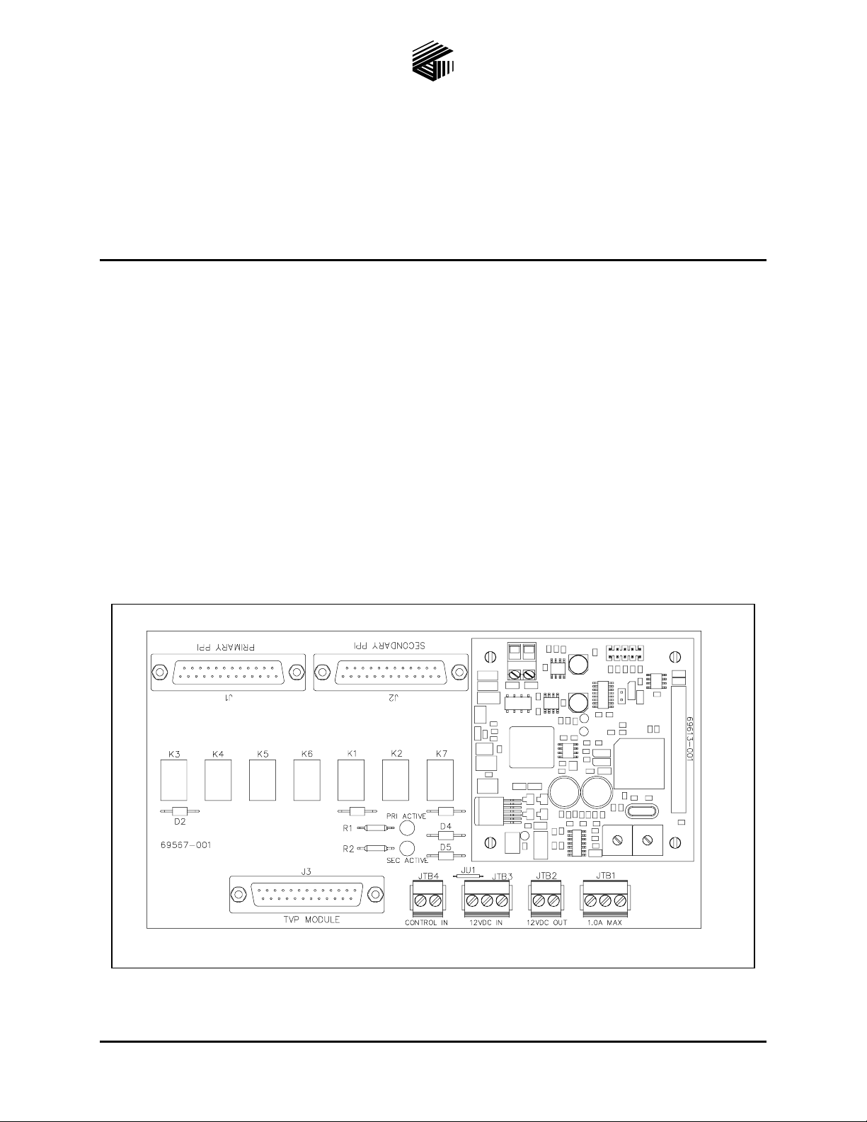
Figure 1. Model 12593-001 Redundant PPI Switching Module
GAI-Tronics Corporation P.O. Box 1060, Readi ng, PA 19607-1060 USA
610-777-1374 800-492-1212 Fax: 610-796-5954
ISIT WWW.GAI-TRONICS.COM FOR PRODUCT LITERATURE AND MANUALS
V
Page 2

Pub. 42004-411A
Model 12593-001 Redundant P P I Switching Module Page: 2 of 6
Hardware Configuration
The Model 12593-001 Redundant PPI Switching Module is comprised of two printed circuit board
assembli e s (PCBAs). The lower b ase board conta ins the lower switc hing rela ys and measures 7.5 L × 4
W inches (190.5 × 102 mm). The r e lay swit chi n g PCBA is equipped w ith seven sma ll DPD T relays, two
LEDs, three 25-pin “D” connectors and four modula r (plug -in type) terminal blocks .
The upper CPU PCBA emp loys a micro-contr oller and ha s two a ddr es s switches (S1 and S2) . The s mall
terminal block located on the opposite side is for external power when used in other applications when
power is not available via the 34-pin DIP connector (J1).
Installation
CAUTION
When instal ling o r replacing this mod ul e, be sure power is not app l ied to
avoid damage to the module circuits.
The Model 12593-001 Redundant PPI Switching Module is designed for mounting in 4-inch Snap Trak
®
When inserting the module in SnapTrak
SnapTrak
Once installed in the SnapTrak
®
to avoid damage to th e module’s print e d circuit boar d and components .
®
, be sure the module edges are secured in the channels so that the module
, exer cise ca re when p ressing the m odule edg es in to the
®
does not dislodge during transport or operation if subjected to vibration. Also, if this module is used with
other modules in the SnapTrak
®
, be sure to leave spacing between modules to facilitate wiring at any
edge-mounted terminal blocks.
Terminations
The Model 12593-001 Redundant PPI Switching Module is equipped with three 25-pin “D” connectors,
and four modular (plug-in type) terminal blocks, which simplify external connections during installation,
and provide quick disconnect if replacement is ever required.
The following is a breakdown of each connector and terminal block and its function(s):
J1 – is the primary PPI card connection; a cable with a 25-pin “D-Sub” connector is required.
J2 – is the secondary PPI card connection; a cable with a 25-pin “D-Sub” connector is required.
®
J3 – is the output connection to the Page/Party
connector is required.
TVP connection module; a cable with a 25-pin “D-Sub”
.
JTB1 – is the f orm “C” dry contact output, whic h c an be used t o activat e additiona l swit chin g modu les,
or for remote status indication. The maximum switching capacity for the contact is 30 V dc @ 1 amp.
JTB2 – is a feed-through 12 V dc power output to additional switching modules.
JTB3 – is the 12 V dc power input to the module.
JTB4 – are the control inputs to the module to activate the relays to switch between primary and
seco ndary PP I cards, whe n a fa ult occurs. Activation at either input r equires dc ground control.
The f ollow ing is a summa ry of each co nnector and ter m inal bloc k f unct ion(s ):
\\s_eng\gtc proddoc s \st andard iom s - current release\42004 instr. manuals \ 42004-411a. doc
05/08
Page 3
Pub. 42004-411A
Model 12593-001 Redundant P P I Switching Module Page: 3 of 6
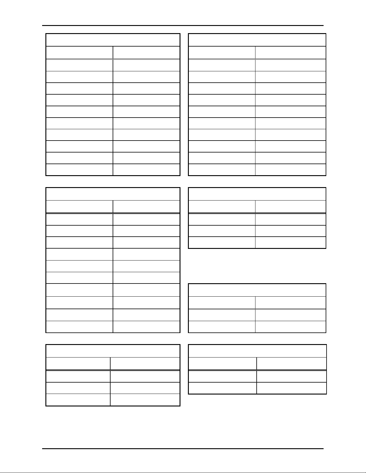
J1 – Primary PPI Card (25-pin D-Sub) J2 – Secondary PPI Card (25-pin D-Sub)
Pin No. Function Pin No. Function
1 & 2 Page Line 1 & 2 Page Line
3 & 4 Party Line 1 3 & 4 Party Line 1
5 & 6 Party Line 2 5 & 6 Party Line 2
7 & 8 Party Line 3 7 & 8 Party Line 3
9 & 10 Party Line 4 9 & 10 Party Line 4
11 & 12 Party Line 5 11 & 12 Party Line 5
13 Ear th ground 13 Ear th ground
15 & 17 Output control (RLY) 15 & 17 Output control (RLY)
20 & 21 Control input (CLS) 20 & 21 Control input (CLS)
14, 16, 18, 19, 22-25 Spare – No connection 14, 16, 18, 19, 22-25 Spare – No connection
J3 – Page/Party® Output (25-pin D-Sub) JTB1 – Relay Contact Output
Pin No. Function Terminal No. Function
1 & 2 Page Line 1 Normally open
3 & 4 Party Line 1 2 Common
5 & 6 Party Line 2 3 Normally closed
7 & 8 Party Line 3
9 & 10 Party Line 4
11 & 12 Party Line 5
13 Earth ground
15 & 17 Output control (RLY)
Terminal No. Function
JTB2 - 12 V dc Power Output
20 & 21 Control input (CLS) 1 12 V (+)
14, 16, 18, 19, 22-25 Spare – No connection 2 12 V (-)
JTB3 – 12 V dc Power Input JTB4 – Switching Control Inputs
Terminal No. Function Terminal No. Function
1 12 V (+) 1 Primary control line
2 12 V (-) 2 Secondar y contr o l li n e
3 GND
\\s_eng\gtc proddoc s \st andard iom s - current release\42004 instr. manuals \ 42004-411a. doc
05/08
Page 4

Pub. 42004-411A
Model 12593-001 Redundant P P I Switching Module Page: 4 of 6
Address Switch Settings
Address switches S1 and S2 on the upper CPU PCBA must each be set to position F for a board address
of FF. When us ing mu ltiple modules, address FF must be set on ALL modules. Address FF allows the
module to operate as a Multi-S tation Simulator (MSS), with its d esignated P PI car ds. Refer to the
oper atio n section for information on the MSS feature.
Operation
The module switches the SmartSeries Page/Party® Stations between the Page/Party® Interfac e (PPI) cards
in th e p rima ry and seco ndary card rac ks. The switching action is in itia ted wh e never a primary MCU or
primary AMI fault occurs in the system. The signals being switched are the page line, party lines 1 and 2,
the r e lay contr ol output (R LY) and t he control input (CL S).
The module has essentially two modes of operation, normal and fault. Each mode is described in detail
below.
Normal Co ndition
®
All relays on the module are de-energized. The SmartSeries Page/Party
the P rimary PPI card (J1) via relays K2 - K6.
stations (J3) are connected to
The module’s CPU PCBA, is connected to the page line of the Secondary PPI card (P2) via relay K7.
The CP U P CBA simulat es all the SmartSeries Page/Party
®
stations by responding to all station polling
requests from the Secondary Master Control Unit (MCU). This action prevents SmartSeries station faults
from occurring in the secondary system.
Fault C onditio n
A fault condition is signaled by connecting either terminal of JTB4 to dc ground. LED1 (Pri-Active) or
LED2 (Sec-Active) illuminate to indicate the active input. In an ADVANCE system application, these
inputs are active if a primary MCU or primary AMI fault occurs. The control signal input is supplied by
an external relay contact.
When activated, relays K1–K7 are energized. Relay K1 contacts are wired to JTB1 and will change state
for the duration of the active condition. Relays K2–K6 switch the SmartSeries Page/Party
®
stations (J3)
to the Secondary PPI card (J2). The CPU PCBA, is connected to the page line of the Primary PPI card
(P1).
\\s_eng\gtc proddoc s \st andard iom s - current release\42004 instr. manuals \ 42004-411a. doc
05/08
Page 5

Pub. 42004-411A
Model 12593-001 Redundant P P I Switching Module Page: 5 of 6
Maintenance
If the module re quires service, c o ntact your Regional Ser vice Ce nter f or a r et urn authorization number
(RA# ) . The module should be s hipp e d prepaid t o GAI- T ronics with a ret urn authorization numb er and a
purchase order number. If the module is under warranty, repairs or a replacement will be made in
accordance with GAI-Tronics’ warranty policy. Please include a written explanation of all defects to
assist our technicians in their troubleshooting efforts.
Call 800-492-1212 inside the USA or 610-777-1374 outside the USA for help identifying the Regional
Service Center closest to y o u.
Troubl eshooting
Problem Solution
SmartSeries station faults are
present in the secondary system.
SmartSeries stations squeal
when party line 1 or 2 are
accessed.
Module LEDs do not illuminate
and r e lays do not s witch when
input control is provided.
Module still does not function after
all checks described in this section.
• Verify 12 V dc power is applied to the module.
• Verify CPU PCBA address is set to FF.
• Verify cables are properly inserted into connectors J1, J2, J3.
• Ensure J1 pins of CPU PCBA are correctly inserted into J4 of
lower relay switching PCBA.
• Verify connectors J 1 , J2, J3 are properly ins erted. If
disconnected, the page, and party lines 1 and 2 will be
unloade d resu lting in osc illation of the Smar tSer ies handset
amplifier.
• Veri fy 12 V dc (-) is being switched to the PRI
and/or SEC
inputs at JTB4
Contact GAI-Tronics service for repair or replacement of the
module.
\\s_eng\gtc proddoc s \st andard iom s - current release\42004 instr. manuals \ 42004-411a. doc
05/08
Page 6

Pub. 42004-411A
Model 12593-001 Redundant P P I Switching Module Page: 6 of 6
Specification s
Electrical
Power Requirements............................................................10.8–13.2 V dc (12 V dc @ 265 mA nominal)
Number of control inputs ........................................................................................................................ 2
Number of fault outputs.......................................................................................................................... 1
Fault output type..................................................................................................... Form “C” dry conta c t
Fault output contact rating................................................................................. 1 A maximum @ 30 V dc
Connections
25-pin “D-Sub”...................................................................................................................................... 3
Modular (plug-in) terminal blocks.......................................................................................................... 4
Minimum terminal block conductor size............................................................... No. 28 AWG (0.5 mm
Maximum terminal block conductor size .............................................................. No. 12 AWG (3.0 mm
Mechanical
Module dimensions ...................................... 7.50 L × 4.00 W × 1.56 H inches (190.5 × 101.6 × 39.7 mm)
Module weight............................................................................................................. 0.43 lbs. (0.20 kg)
2
2
)
)
Enviro nmental
Temperature range (operating/storage).................................................... -4° F to 158° F (-20° C to 70° C)
Humidity ....................................................................................... 85% non-condensing relative humidity
\\s_eng\gtc proddoc s \st andard iom s - current release\42004 instr. manuals \ 42004-411a. doc
05/08
Page 7

Warranty
Equipment. GAI-Tronics warrants for a period of one (1) year from the date of shipment, that any
GAI-Tronics equipment supplied hereunder shall be free of defects in material and workmanship, shall
comply with the then-current product specifications and product literature, and if applicable, shall be fit
for the purpose specified in the agreed-upon quotation or proposal document. If (a) Seller’s goods prove
to be defective in workmanship and/or material under normal and proper usage, or unfit for the purpose
specified and agreed upon, and (b) Buyer’s claim is made within the warranty period set forth above,
Buyer may return such goods to GAI-Tronics’ nearest depot repair facility, freight prepaid, at which time
they will be repaired or replaced, at Seller’s option, without charge to Buyer. Repair or replacement shall
be Buyer’s sole and exclusive remedy. The warranty period on any repaired or replacement equipment
shall be the greater of the ninety (90) day repair warranty or one (1) year from the date the original
equipment was shipped. In no event shall GAI-Tronics warranty obligations with respect to equipment
exceed 100% of the total cost of the equipment supplied hereunder. Buyer may also be entitled to the
manufacturer’s warranty on any third-party goods supplied by GAI-Tronics hereunder. The applicability
of any such third-party warranty will be determined by GAI-Tronics.
Services. Any services GAI-Tronics provides hereunder, whether directly or through subcontractors,
shall be performed in accordance with the standard of care with which such services are normally
provided in the industry. If the services fail to meet the applicable industry standard, GAI-Tronics will
re-perform such services at no cost to buyer to correct said deficiency to Company's satisfaction provided
any and all issues are identified prior to the demobilization of the Contractor’s personnel from the work
site. Re-performance of services shall be Buyer’s sole and exclusive remedy, and in no event shall GAITronics warranty obligations with respect to services exceed 100% of the total cost of the services
provided hereunder.
Warranty Periods. Every claim by Buyer alleging a defect in the goods and/or services provided
hereunder shall be deemed waived unless such claim is made in writing within the applicable warranty
periods as set forth above. Provided, however, that if the defect complained of is latent and not
discoverable within the above warranty periods, every claim arising on account of such latent defect shall
be deemed waived unless it is made in writing within a reasonable time after such latent defect is or
should have been discovered by Buyer.
Limitations / Exclusions. The warranties herein shall not apply to, and GAI-Tronics shall not be
responsible for, any damage to the goods or failure of the services supplied hereunder, to the extent
caused by Buyer’s neglect, failure to follow operational and maintenance procedures provided with the
equipment, or the use of technicians not specifically authorized by GAI-Tronics to maintain or service the
equipment. THE WARRANTIES AND REMEDIES CONTAINED HEREIN ARE IN LIEU OF AND
EXCLUDE ALL OTHER WARRANTIES AND REMEDIES, WHETHER EXPRESS OR IMPLIED BY
OPERATION OF LAW OR OTHERWISE, INCLUDING ANY WARRANTIES OF
MERCHANTABILITY OR FITNESS FOR A PARTICULAR PURPOSE.
Return Policy
If the equipment requires service, contact your Regional Service Center for a return authorization number
(RA#). Equipment should be shipped prepaid to GAI-Tronics with a return authorization number and a
purchase order number. If the equipment is under warranty, repairs or a replacement will be made in
accordance with the warranty policy set forth above. Please include a written explanation of all defects to
assist our technicians in their troubleshooting efforts.
Call 800-492-1212 (inside the USA) or 610-777-1374 (outside the USA) for help identifying the
Regional Service Center closest to you.
(Rev. 10/06)
 Loading...