

Page 1
Pub. 42003-231A
GAI-TRONICS® CORPORATION
A HUBBELL COMPANY
ICS Subset Extension Cable Assembly
Replacement Kit
MODELS 12587-101 & 12587-102
Confidentiality Notice
This manual is provided solely as an operational, installation, and maintenance guide and contains
sensitive business and technical information that is confidential and proprietary to GAI-Tronics. GAITronics retains all intellectual property and other rights in or to the information contained herein, and
such information may only be used in connection with the operation of your GAI-Tronics product or
system. This manual may not be disclosed in any form, in whole or in part, directly or indirectly, to any
third party.
General Information
The Model 12587-101 and 12587-102 ICS Subset Extension Cables allow the ICS remote subset to be
positioned up to 100 feet from the remote amplifier. Model 12587-101 Extension Cable allows the
interconnection of multiple cable assemblies for additional length. Model 12587-102 includes a stainless
steel wall plate to allow for a wall receptacle installation. Both cable assemblies are compatible with all
ICS Page/Party
®
remote subsets.
The Model 12587-101 consists of the following:
Qty Description
1 Cable, 25-foot, 25-conductor, PVC jack cable with molded DB25 connectors on each end
2 4-40 male/female hex jack screws
The Model 12587-102 includes the following components:
Qty Description
1 Cable, 25-foot, 25-conductor, PVC jack cable with molded DB25 connectors on each end
1 Wall plate, stainless steel with DB25 opening
2 Wall plate attachment screws
2 4-40 male/female hex jack screws
GAI-Tronics Corporation 400 E. Wyomissing Ave. Mohnton, PA 19540 USA
610-777-1374 800-492-1212 Fax: 610-796-5954
ISIT WWW.GAI-TRONICS.COM FOR PRODUCT LITERATURE AND MANUALS
V
Page 2
Pub. 42003-231A
M
ODELS 12587-101 & -102 ICS SUBSET EXTENSION CABLE ASSEMBLY REPLACEMENT KIT Page: 2 of 3
Installation as a W all Receptacle
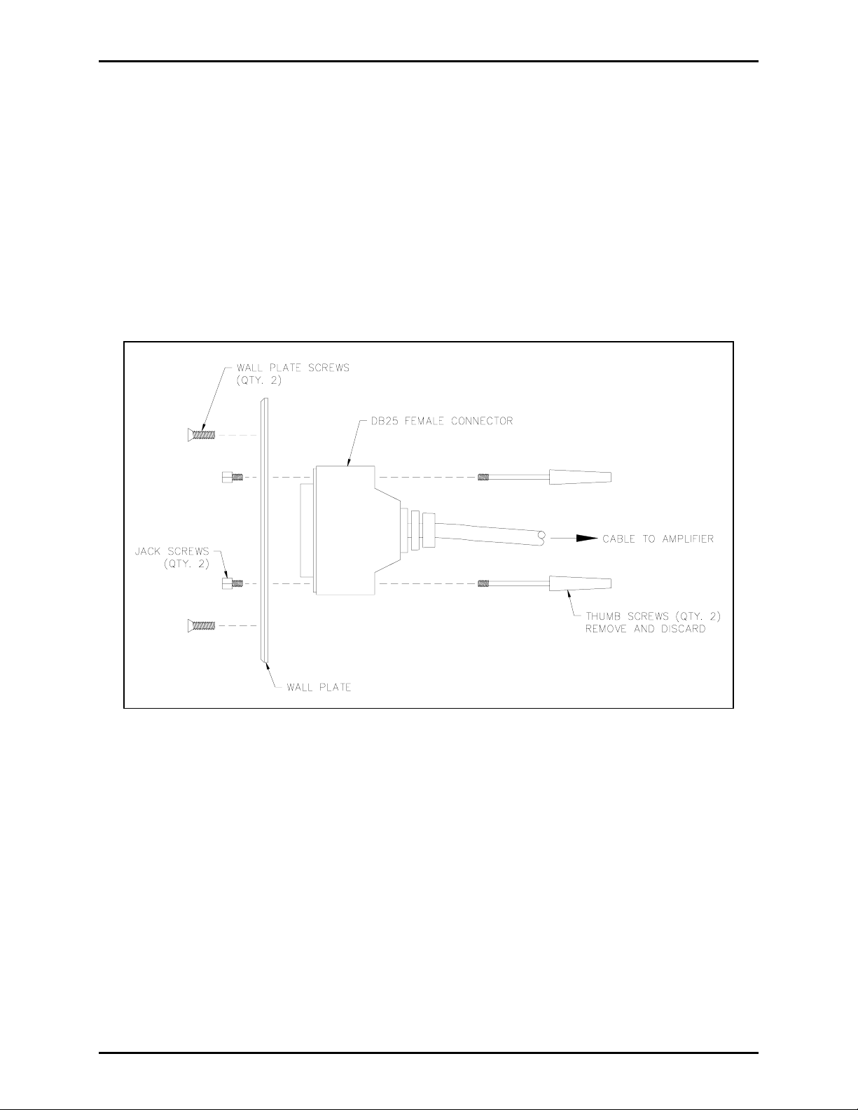
1. Arrange the cable so that the DB25 male connector is located at the amplifier enclosure and the
cable’s DB25 female connector is located at the wall receptacle. Remove the thumb screws from the
female DB25 connector. See Figure 1.
2. Route the 25-foot cable/plug assembly inside the wall from the amplifier location to the desired wall
receptacle location, and mount it by using a single gang wall plate mounting bracket (such as L-Com
WPMB1). Make the connection in accordance with the appropriate electrical code.
3. Install the DB25 female connector on the supplied wall plate, using the included two 4-40 jack
screws to attach the connector to the wall plate.
Figure 1. Installation as a Wall Receptacle
4. Install the wall plate using the two mounting screws provided.
5. After all connections have been made, plug the DB25 male connector into the receptacle at the
amplifier enclosure.
6. Plug the subset plug into the DB25 wall receptacle. Be sure that the connector housing seats fully
into place, and use the DB25 connector thumb screws to secure the connector.
f:\standard ioms - current release\42003 kit manuals\42003-231a.doc
04/10
Page 3

Pub. 42003-231A
M
ODELS 12587-101 & -102 ICS SUBSET EXTENSION CABLE ASSEMBLY REPLACEMENT KIT Page: 3 of 3
Installation as a Subset Extension Cord
1. Arrange the extension cable so that the DB25 male connector is connected at the amplifier enclosure
or wall receptacle. Remove the thumb screws from the DB25 female connector. Install the two jack
screws provided. See Figure 2.
2. Plug the cable’s female DB25 connector into the remote subset cable’s (or an additional extension
cable’s) DB25 male connector and secure the connectors. Additional extension cables may be
connected in order to attain the necessary length. The maximum total length of the combined
extension cables is 100 feet.
3. When a cable is of sufficient length to reach the subset has been assembled, connect the female
DB25 connector at the end of the cable to the receptacle on the remote subset.
Figure 2. Installation as a Subset Extension
f:\standard ioms - current release\42003 kit manuals\42003-231a.doc
04/10
Page 4

Warranty
Equipment. GAI-Tronics warrants for a period of one (1) year from the date of shipment, that any
GAI-Tronics equipment supplied hereunder shall be free of defects in material and workmanship, shall
comply with the then-current product specifications and product literature, and if applicable, shall be fit
for the purpose specified in the agreed-upon quotation or proposal document. If (a) Seller’s goods prove
to be defective in workmanship and/or material under normal and proper usage, or unfit for the purpose
specified and agreed upon, and (b) Buyer’s claim is made within the warranty period set forth above,
Buyer may return such goods to GAI-Tronics’ nearest depot repair facility, freight prepaid, at which time
they will be repaired or replaced, at Seller’s option, without charge to Buyer. Repair or replacement shall
be Buyer’s sole and exclusive remedy. The warranty period on any repaired or replacement equipment
shall be the greater of the ninety (90) day repair warranty or one (1) year from the date the original
equipment was shipped. In no event shall GAI-Tronics warranty obligations with respect to equipment
exceed 100% of the total cost of the equipment supplied hereunder. Buyer may also be entitled to the
manufacturer’s warranty on any third-party goods supplied by GAI-Tronics hereunder. The applicability
of any such third-party warranty will be determined by GAI-Tronics.
Services. Any services GAI-Tronics provides hereunder, whether directly or through subcontractors,
shall be performed in accordance with the standard of care with which such services are normally
provided in the industry. If the services fail to meet the applicable industry standard, GAI-Tronics will
re-perform such services at no cost to buyer to correct said deficiency to Company's satisfaction provided
any and all issues are identified prior to the demobilization of the Contractor’s personnel from the work
site. Re-performance of services shall be Buyer’s sole and exclusive remedy, and in no event shall GAITronics warranty obligations with respect to services exceed 100% of the total cost of the services
provided hereunder.
Warranty Periods. Every claim by Buyer alleging a defect in the goods and/or services provided
hereunder shall be deemed waived unless such claim is made in writing within the applicable warranty
periods as set forth above. Provided, however, that if the defect complained of is latent and not
discoverable within the above warranty periods, every claim arising on account of such latent defect shall
be deemed waived unless it is made in writing within a reasonable time after such latent defect is or
should have been discovered by Buyer.
Limitations / Exclusions. The warranties herein shall not apply to, and GAI-Tronics shall not be
responsible for, any damage to the goods or failure of the services supplied hereunder, to the extent
caused by Buyer’s neglect, failure to follow operational and maintenance procedures provided with the
equipment, or the use of technicians not specifically authorized by GAI-Tronics to maintain or service the
equipment. THE WARRANTIES AND REMEDIES CONTAINED HEREIN ARE IN LIEU OF AND
EXCLUDE ALL OTHER WARRANTIES AND REMEDIES, WHETHER EXPRESS OR IMPLIED BY
OPERATION OF LAW OR OTHERWISE, INCLUDING ANY WARRANTIES OF
MERCHANTABILITY OR FITNESS FOR A PARTICULAR PURPOSE.
Return Policy
If the equipment requires service, contact your Regional Service Center for a return authorization number
(RA#). Equipment should be shipped prepaid to GAI-Tronics with a return authorization number and a
purchase order number. If the equipment is under warranty, repairs or a replacement will be made in
accordance with the warranty policy set forth above. Please include a written explanation of all defects to
assist our technicians in their troubleshooting efforts.
Call 800-492-1212 (inside the USA) or 610-777-1374 (outside the USA) for help identifying the
Regional Service Center closest to you.
(Rev. 10/06)
 Loading...