

Page 1
GE - GD
ISTRUZIONI PER LUSO
OPERATING INSTRUCTIONS
GEBRAUCHSANWEISUNG
MODE DEMPLOI
INSTRUCCIONES DE USO
Page 2

Page 3

Sede legale: Via C. Gomes, 16-20124 Milano
Direzione – Uffici –Stabilimento:
20087 Robecco sul Naviglio – Milano – Italia
S.p.A.
Telefoni: 029470371 (5 linee)
029471410 (2 linee) – 029471654 – Fax: 029470888
capitale sociale L. 200.000.000 i. v.
r.e.a. 1387376 – MI – iscr.reg..impr. MI-2000-51402
P.Iva: IT – 13054780153 Cod. Fisc. 02069680367
www.gaggia.it - E-mail: gaggia@gaggia.it
DICHIARAZIONE DI CONFORMITA’ CE – DECLARATION DE CONFORMITE CE
EG-KONFORMITÄTSERKLÄRUNG – EC DECLARATION OF CONFORMITY
DECLARACIÓ DE CONFORMIDAD CE
La Ditta Gaggia s.p.a
.
Dichiara sotto la propria responsabilità chi i prodotti: Macchina per caffè per uso professionale
Déclare que les produits suivants: Machines à café expresso pour usage professionnel
Erklärt, dass die folgenden Produkte: Gewerbe Espresso Kaffeemaschinen
Declare that the following product: Espresso coffe machines for professional use
Declara bajo nuestra responsabilidad que el producto: Máquina para café de uso profesional
Modelli – Modèles
Modelle – Models – Modelo
GE – GD 2 – 3 – 4 gr
al quale è riferita questa Dichiarazione , secondo quanto prescritto dalle direttive specifiche:
à laquelle se réfère cette dèclaration, selon les prescriptions des directives specifiques:
auf das sich diese Erklärung bezieht, Entsprechend der Vorschriften der spezifischen Richtlinien:
to which this declaration relates is, according to the provisions of the specific directives:
al cual se refiere esta Declaración, de acuerdo con lo prescrito por las especificas directivas:
98/37/CE;73/23/CE, 93/68/CE;89/336/CE, 93/68/CE, 92/31/CE;97/23/CE
è conforme alle seguenti norme:
conforme aux normes suivantes:
in Übereinstimmung mit den folgenden Normen:
It complies with the following norms:
es conforme a las sigientes normas:
EN 292-1; EN292-2; EN 60335-1; IEC 335-2-75 + A1: 98
EN 55014-1: 1993 + A1: 1997; EN55014-2:1997
EN61000-3-2: 1995 + A13: 1997 EN 61000-3-3:1995
Raccolta M ed.78; Raccolta S Ed.78; Raccolta E; Art. 15 D.M. 21.5.74; Raccolta VRS Ed.72
Descrizione attrezzatura a pressione – Decription de l’appareillage sous pression - Beschreibung der unter Druck
stehenden Geräte – Pressure device description – Descripción de los equipos de presión
Capacità it – Capacité – Fähigkeit it –
Capacity it – Potencia it
2 gr 3 gr 4 gr
13 21 28
Numero scambiatore – Numéro de l’échangeur
Nummer des Austauschers –
Exehanger number Número intercambiador
2 gr 3 gr 4 gr
Caldaia
Chaudière – Kessel
Boiler - Caldera
Scambiatore
Echangeur-Austauscher
Exchanger - Intercambiador
Pressione Max. pa/bar
Pressin – Druck
Pressure - Presión
Temp. Max °C
Température – Temperatur
Temperature - Temperatura
0,18/1,8 131
Pressione Max. pa/bar
Pressin – Druck
Pressure - Presión
Temp. Max °C
Température-Temperatur
Temperature-Temperatura
Fluide – Flüssig
0,11/11 131
Fluido
Fluide – Flüssig
Fluid – Fluido
Acqua / Vapore
Eau / Vapeur – Wasser / Dampf
Water / Steam – Agua / Vapor
Fluido
Fluid - Fluido
Acqua
Eau-Wasser
Water-Agua
Capacità it
Capacité-Fähigkeit
Capacity - Potencia
0,390 2 3 4
Robecco sul Naviglio, 21/11/2001
01
La presente dichiarazione perde la sua validità se la macchina viene modificata senza l a nostra espressa autorizzazione.
La Présente déclaration perd sa validité dés lors que la machine est modifiée sans notre expresse autorisation.
Die vorliegende Erklärung verliert ihre Gültigkeit, wenn die Maschine ohne unsere ausdrückliche Genehmigung verändert wird.
The present declaration will become invalid should the machine be modified without our specific authorization.
La presente declaraciòn pierde su validez si la máquina es modificada sin nuestra expresa autorización.
Page 4
IMPORTANTE
Egregio Cliente, La informiamo tutte le nostre macchine prodotte sono commercializzate in
conformità alla Direttiva 97/23/CE, recepita con Decreto Legislativo n. 93 del 25 febbraio
2000.
Le disposizioni del Decreto sopra menzionato si applicano alla progettazione, alla
fabbricazione, alla valutazione di conformità della attrezzature a pressione degli insiemi
sottoposti ad una pressione massima ammissibile PS superiore a 0,5 bar.
Come specificato nell’articolo 19, comma 3 del suddetto Decreto Legislativo, è previsto
che l’utilizzatore deve comunicare la messa in servizio delle attrezzature a pressione e
degli insiemi all’ISPESL e all’azienda unità sanitaria locale competenti per il territorio.
LA INVITIAMO DI CONSEGUENZA A COMPILARE IL MODELLO ALLEGATO 1 (VEDI
ULTIME PAGINE DI QUESTO MANUALE), IN DUPLICE COPIA E A SPEDIRLO ALLE
SEDI DI COMPETENZA TERRITORIALE ASL E ISPESL.
N.B. La mancata comunicazione può comportare l’applicazione
dell’Art. 650 del codice penale.
Per l’indirizzo dei Dipartimenti e competenze territoriali ISPESL, può utilizzare l’allegato 2
(vediuItime pagine di questo manuale).
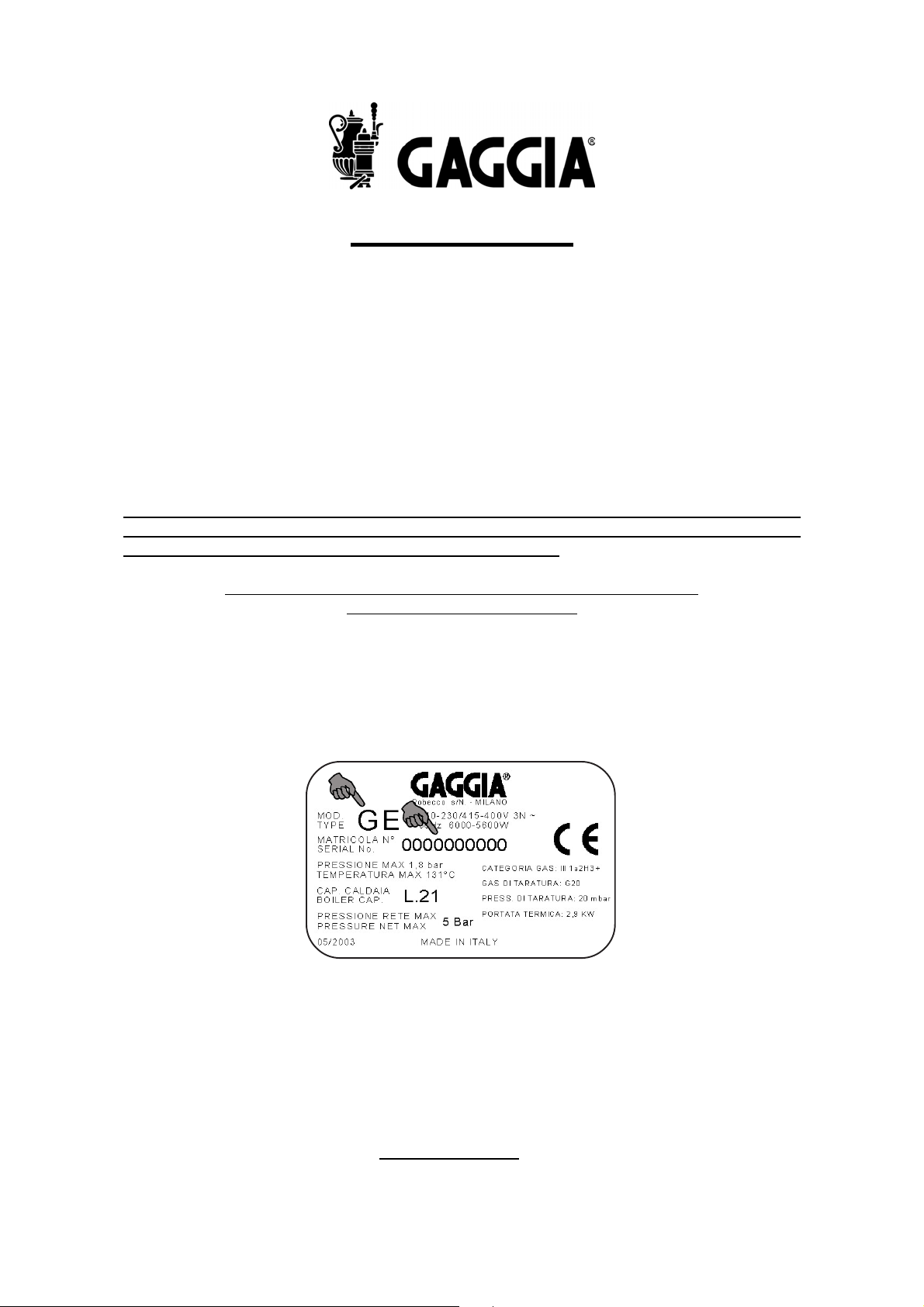
Per quanto riguarda il modello, ed il numero di fabbrica della macchina per caffè da
installare, li può rilevare dalla targhetta dati posta sull’apparecchiatura stessa.
Esempio:
Ci congraturiamo con lei per l’acquisto di questa macchina per caffè espresso e La
ringraziamo per la fiducia e disponibilità che ci ha dimostrato.
Prima di mettere in funzione la macchina, Le consigliamo di leggere attentamente le
istruzioni per l’uso che Le spiegano come utilizzarla, pulirla e mantenerla in perfetta
efficienza.
Rimaniamo a Sua disposizione per qualsiasi informazione.
ONLY FOR ITALY
Page 5

1
/*
Gentile cliente,
la ringraziamo per la fiducia accordataci con l’acquisto di un nostro prodotto.
Se Lei avrà la costanza di seguire attentamente le indicazioni contenute nel
presente manuale, siamo certi che potrà apprezzare nel tempo e con soddisfazione la qualità della nostra macchina.
La preghiamo di leggere attentamente le indicazioni contenute nel manuale che
riguardano l’uso corretto del nostro prodotto, in conformità alle prescrizioni essenziali di sicurezza.
We thank you for your custom in the purchase of this product.
By carefully following the instructions contained in this manual you will be sure to
appreciate the quality of our machine.
Please therefore carefully read the instructions of use contained in this manual,
which comply with essential safety regulations.
,
.
Sehr geehrter Kunde,
wir danken Ihnen für das uns durch den Erwerb eines unserer Produkte
entgegengebrachte Vertrauen.
Wenn Sie die Ausdauer haben, aufmerksam die im vorliegenden Handbuch
enthaltenen Hinweise zu beachten, sind wir gewiß, daß Sie lange und mit
Zufriedenheit die Qualität unserer Maschine schätzen werden können.
Wir bitten Sie, aufmerksam die im Handbuch enthaltenen Hinweise bezüglich
der richtigen Verwendung unseres Produktes in Übereinstimmung mit den
wesentlichen Sicherheitsvorschriften zu lesen.
Cher client,
Nous vous remercions de la confiance que vous nous avez manifestée en
achetant notre produit.
Si vous suivez attentivement les indications contenues dans le présent manuel,
nous sommes certains que vous apprécierez la qualité de notre machine.
Nous vous prions de lire attentivement les indications contenues dans le manuel
sur l’utilisation correcte de notre produit, en conformité avec les prescriptions
essentielles de sécurité.
-
Estimado cliente:
Le agradecemos por la confianza que nos otorga con la compra de nuestro
producto.
Si Ud. tendrá la constancia de seguir atentamente las indicaciones contenidas
en este manual, estamos seguros de que podrá apreciar con satisfacción y a lo
largo del tiempo la calidad de nuestra máquina.
Le rogamos que lea atentamente las indicaciones que se refieren al empleo
correcto de nuestro producto contenidas en el manual, en conformidad con las
prescripciones esenciales de seguridad.
Page 6

Prima della messa in funzione, leggere attentamente il manuale di istruzioni
Carefully read the following instruction booklet before starting up the machine.
Lesen Sie vor der Inbetriebnahme aufmerksam die Bedienungsanleitung.
Avant la mise en service, lire attentivement le manuel d’instructions.
Antes de la puesta en funcionamiento, hay que leer atentamente el manual de instrucciones
Attenzione! Togliere l’alimentazione elettrica prima di asportare le protezioni
Carefully read the following instruction booklet before starting up the machine.
Achtung! Schalten Sie vor dem Entfernen der Schutzabdeckungen die Stromzufuhr ab
Attention ! Débrancher l’alimentation électrique, avant d’enlever les protections.
¡Atención! Desconectar la alimentación eléctrica antes de extraer las protecciones
Attenzione! Superfici calde
Important ! Hot surfaces.
Achtung! Oberfläche heiß
Attention ! Surfaces chaudes.
¡Atención! Superficies calientes
Attenzione! Operazioni particolarmente importanti e/o pericolose
Important! Particularly important and/or delicate operations
Achtung! Besonders wichtige und / oder gefährliche Arbeitsgänge.
Attention ! Opérations particulièrement importantes et/ou dangereuses.
¡Atención! Operaciones particularmente importantes y/o peligrosas
Importante! Interventi necessari al buon funzionamento.
Important ! Operations essential to guarantee efficient function
Wichtig! Für eine gute Funktionsweise erforderliche Maßnahmen.
Important ! Interventions nécessaires au bon fonctionnement.
¡Importante! Intervenciones necesarias para el buen funcionamiento.
Interventi che possono essere svolti a cura dell’utente
Operations which may be carried out by the user
Maßnahmen, die durch den Anwender vorgenommen werden können
Interventions pouvant être effectuées par l’utilisateur.
Intervenciones que pueden ser realizadas por el usuario
Interventi che devono essere svolti esclusivamente da un installatore o un tecnico autorizzato.
Interventions to be carried out exclusively by an installer or authorized technician.
Eingriffe, die nur von einem Installateur oder von einem autorisierten Techniker vorgenommen werden dürfen.
Interventions à effectuer uniquement par un installateur ou un technicien autorisé.
Intervenciones que tienen que ser efectuadas sólo por el instalador o el técnico Autorizado.
6
Page 7

ITALIANO
INDICE
ITALIANO
7 - 30
ENGLISH 31 - 54
DEUTSCH 55 - 78
FRANÇAIS 79 - 102
ESPAÑOL 103 - 126
1 UTILIZZO E CONSERVAZIONE DEL
MANUALE D’ISTRUZIONI........................... 8
2 USO PREVISTO DELLA MACCHINA........ 8
3 AVVERTENZE DI SICUREZZA.................. 9
4 CARATTERISTICHE TECNICHE............... 10
5 INSTALLAZIONE......................................... 11
5.1 ALLACCIAMENTO IDRICO.................. 11
5.2 ALLACCIAMENTO ELETTRICO .......... 11
5.3 ALLACCIAMENTO GAS ....................... 11
6 MESSA IN SERVIZIO.................................. 12
6.1 GIGLIEUR PER CAFFE’ LUNGHI .... 13
6.2 REGOLAZIONE DEL PRESSOSTATO. 13
6.3 TARATURA PRESSOSTATO POMPA 13
6.4 FILTRI CAFFÈ CORREDO MACCHINA 13
6.5 SOSTITUZIONE DEL TERMOSTATO PER
DIMINUIRE LA TEMPERATURA DEL
GRUPPO EROGAZIONE CAFFE’..............14
6.6 BECCUCCI CORREDO
MACCHINA...................................................14
7 FUNZIONAMENTO / USO E
PROGRAMMAZIONE ................................ 15
7.1 PROGRAMMAZIONE DOSE CAFFE’.. 15
7.2 PROGRAMMAZIONE DOSI TEA
(ACQUA CALDA)......................................... 17
7.3 EROGAZIONE CAFFE’..........................18
7.4 DOSE CAFFE’ IN CONTINUO..............18
7.5 FUNZIONI SPECIALI’............................ 19
7.6 EROGAZIONE TEA’.............................. 20
7.7 FUNZIONA CAPPUCCINO E LATTE... 21
7.8 PROGRAMMAZIONE ED EROGAZIONE
CAPPUCCINO............................................. 22
7.9 PROGRAMMAZIONE ED EROGAZIONE
LATTE.......................................................... 22
7.10 ULTERIORE FUNZIONI PER
MACCHINA PROVVISTA DI DISPLAY........23
7.11 SEGNALAZIONE DI ALLARMI........... 26
8 RIGENERAZIONE DEL DEPURATORE... 27
9 REGOLAZIONE GAS................................. 28
10 MANUTENZIONE E CONSIGLI UTILI..... 29
11 RISOLUZIONE INCONVENIENTI............ 30
12 SMANTELLAMENTO DELLA
MACCHINA ................................................ 30
7
Page 8

ITALIANO
1 – UTILIZZO E CONSERVAZIONE DEL MANUALE
D’ISTRUZIONI
Il presente manuale di istruzioni è indirizzato all’utente della macchina, al proprietario al tecnico installatore e deve essere sempre
a disposizione per qualsiasi eventuale consultazione.
Il manuale è destinato all’utilizzatore, al manutentore ed
all’installatore della macchina.
Il manuale di istruzioni serve per indicare l’utilizzo della macchina
previsto nelle ipotesi di progetto, le sue caratteristiche tecniche e
per fornire indicazioni per l’uso corretto, la pulizia la regolazione e
l’uso; fornisce inoltre importanti indicazioni per la manutenzione,
per eventuali rischi residui e comunque per lo svolgimento di operazioni da svolgere con particolare attenzione.
Il presente manuale è da considerare parte della macchina e deve
essere CONSERVATO PER FUTURI RIFERIMENTI fino allo smantellamento finale della macchina.
Il manuale di istruzioni deve essere sempre disponibile per la consultazione e conservato in luogo protetto ed asciutto.
In caso di smarrimento o danneggiamento, l’utente può richiedere
un nuovo manuale al costruttore o al proprio rivenditore indicando
il modello della macchina ed il numero di matricola della stessa
visibile sulla targhetta di identificazione.
2 – USO PREVISTO DELLA MACCHINA
La macchina deve essere fatta funzionare da un solo operatore.
L’operatore addetto deve aver letto e ben compreso le istruzioni
contenute in questo fascicolo in modo da fare funzionare correttamente la macchina.
Questa macchina, è un apparecchio adatto alla preparazione professionale di caffè espresso con miscela di caffè, al prelievo ed
all’erogazione di acqua e / o di vapore.
I suoi componenti sono costruiti in materiali atossici e duraturi, e
sono facilmente accessibili ad interventi di pulizia e di manutenzione.
Questa macchina e adatta esclusivamente per uso interno.
Temperatura ambiente per il corretto funzionamento della macchina: 5°C ÷ 40°C.
Il presente manuale rispecchia lo stato della tecnica al momento
della sua redazione, il fabbricante si riserva il diritto di aggiornare
la produzione ed i manuali successivi senza l’obbligo di aggiornarne anche le versioni precedenti.
Il costruttore si ritiene sollevato da eventuali responsabilità in caso
di:
- uso improprio o non corretto della macchina da caffè
- uso non conforme a quanto espressamente specificato nella
presente pubblicazione
- gravi carenza nella manutenzione prevista e consigliata
- modifiche sulla macchina o qualsiasi intervento non autorizzato
- utilizzo di ricambi non originali o specifici per il modello
- inosservanza totale o anche parziale delle istruzioni
- Eventi eccezionali
8
Page 9

ITALIANO
3 – AVVERTENZE DI SICUREZZA
E’ consentito l’utilizzo solo a persone adulte che abbiano attentamente letto e ben compreso questo manuale ed ogni indicazione
di sicurezza in esso contenuta.
L’utilizzatore non deve toccare la macchina a piedi umidi o bagnati, nonché utilizzarla a piedi nudi. Nonostante l’utilizzo di una messa a terra della macchina, si consiglia l’uso di una pedana di legno
e di un impianto salvavita conforme alle disposizioni delle leggi
locali per evitare al massimo il rischio di shock elettrici.
L’utilizzatore è responsabile verso terzi della zona di lavoro.
L’installatore, l’utilizzatore ed il manutentore hanno l’obbligo di segnalare al costruttore eventuali difetti o deterioramenti che possono compromettere l’originale sicurezza dell’impianto.
L’installatore ha l’obbligo di verificare le corrette condizioni ambientali, in modo da garantire la sicurezza e l’igiene dell’utilizzatore
e degli utenti.
L’installazione deve essere effettuata esclusivamente da personale autorizzato e qualificato.
Utilizzare la macchina solo in presenza di luce idonea.
Per ragioni di sicurezza bisogna sostituire tempestivamente e con
ricambi originali, le parti usurate o danneggiate.
Controllare con regolarità che il cavo di alimentazione sia in perfetto stato. In nessun caso si deve riparare il cavo eventualmente
danneggiato con nastro isolante o con morsetti.
Non esporre la macchina ad agenti atmosferici (sole, pioggia ecc.).
La sosta prolungata (fermo macchina) a temperatura inferiore a
0°C (zero gradi centigradi), può provocare gravi danneggiamenti o
rotture delle tubazioni e della caldaia; prima di ogni sosta prolungata svuotare completamente il circuito idrico.
Non toccare con le mani o altre parti del corpo i beccucci del caffè
e le lance d’acqua calda e vapore, poiché i liquidi o il vapore erogati sono surriscaldati e possono provocare ustioni.
Fare attenzione a non fare funzionare la macchina senz’acqua.
Eventuali occlusioni possono provocare getti imprevisti di liquido o
vapore con gravi conseguenze. Mantenere il più possibile l’acqua
pulita usando filtri ed addolcitori.
Le tazze e le tazzine devono essere accuratamente asciugate prima di essere appoggiate sull’apposito piano.
E’ vietato rimuovere le protezioni e/o i dispositivi di sicurezza previsti sulla macchina.
I componenti dell’imballaggio devono essere consegnati negli appositi centri di smaltimento e in nessun caso lasciati incustoditi o
alla portata di bambini, animali o di persone non autorizzate.
La ditta costruttrice declina ogni responsabilità per danni a cose,
persone od animali causati da eventuali interventi sulla macchina
di persone non qualificate o non autorizzate a queste mansioni.
Qualora vengano effettuati interventi di riparazioni non autorizzate
sulla macchina o vengano utilizzati ricambi non originali vengono
a decadere le condizioni di garanzia e pertanto la ditta costruttrice
si riserva il diritto di non riconoscerne più la validità.
L’utilizzatore deve attenersi alle norme di sicurezza vigenti nel Paese d’installazione, oltre alle regole dettate dal comune buon senso ed assicurarsi che siano effettuate correttamente le periodiche
operazioni di manutenzione.
Non effettuare la pulizia interna della macchina con tensione o la
spina inserita e comunque non utilizzare getti d’acqua o detergenti.
9
Page 10
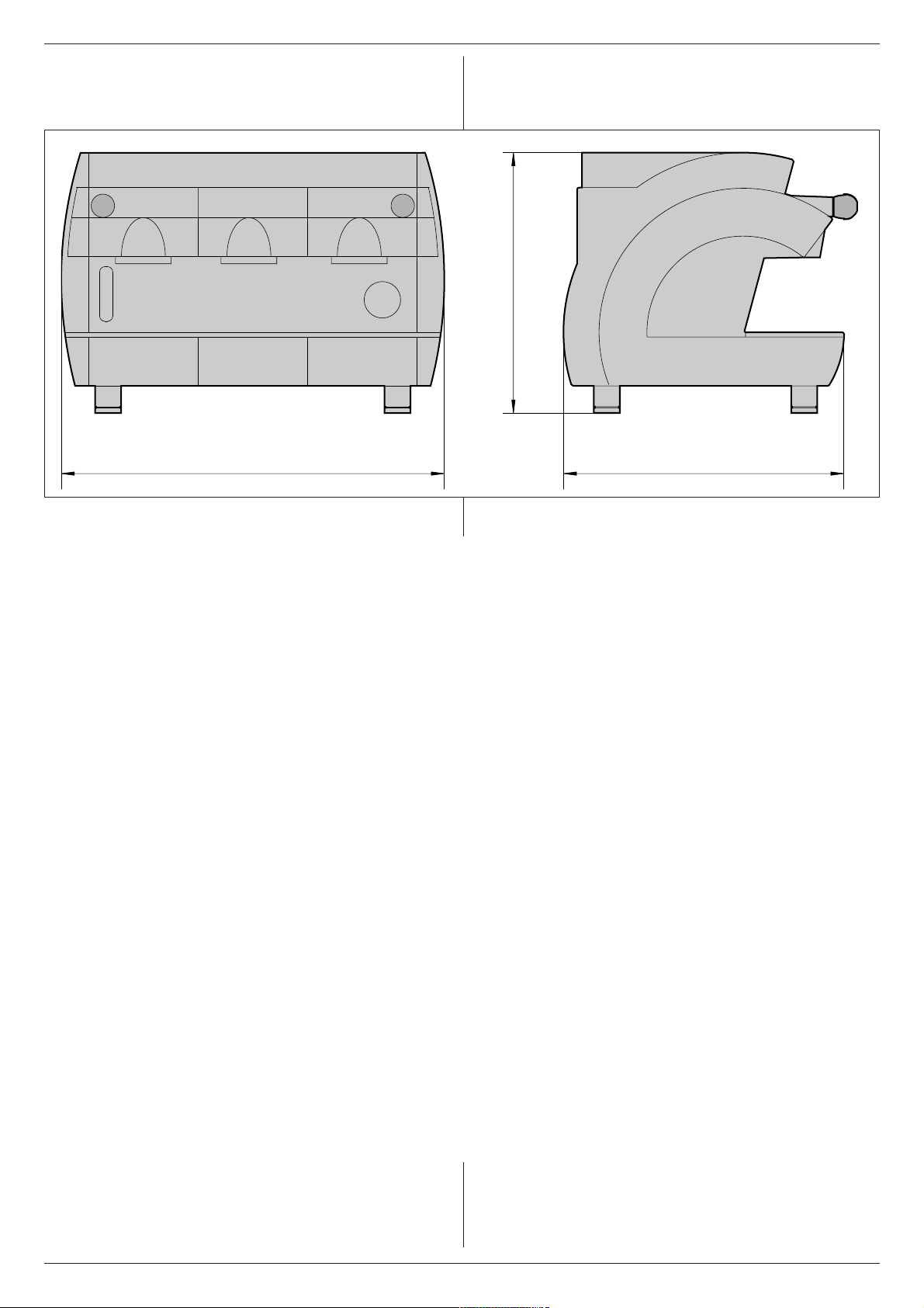
4 – CARATTERISTICHE TECNICHE
grupp
grupp
g
p
pomp
g
ITALIANO
H
Fig.4.01
B
2 gruppi3
Dimensioni B 760 970 1180
H 500 500 500
L 540 540 540
Peso k
acità caldaia L 13 21 28
Ca
Potenza assorbita resistenza caldaia
240 / 415 V 3 N ~ W 4760 5950 7140
230 / 400 V 3 N ~ W 4370 5465 6555
V 120 ~ W 4760 5950 7140
Potenza assorbita resistenza caldaia ECO
max
70 90 110
L
i4
i
240 / 415 V 3 N ~ W 3170 3950 4750
230 / 400 V 3 N ~ W 2900 3640 4360
V 120 ~ W 3170 3950 4750
Motore
Potenza totale assorbita
Riscaldamento
a W 165 165 165
230-240/400-415 V 3 N ~ W 5200 6200 7200
as Kcal/h 1700 2500 3400
10
Page 11

ITALIANO
5 – INSTALLAZIONE
A - RETE IDRICA
B - CONDOTTO DI SCARICO
C - CONDUTTURA GAS
D - INTERRUTTORE DI PROTEZIONE
E - DEPURATORE
F - RUBINETTO ALIMENTAZIONE CALDAIA
G - SCODELLINO DI SCARICO
H - VALVOLA GAS
I - CAVO DI ALIMENTAZIONE
Prima di procedere all’installazione, è necessario verificare che :
-non si presentino ammaccature segni di urti o deformazioni
1 non si presentino zone bagnate o segni che possano portare
a supporre che l’imballaggio sia stato esposto ad intemperie
2 non si presentino segni di manomissioni
Dopo la verifica che il trasporto sia avvenuto in modo corretto, pro-
cedere all’installazione.
Verificare che l’apparecchio sia installato su una superficie piana
adatta a sostenerne il peso ( vedere al capitolo 4 “Caratteristiche
Tecniche”) e avendo cura di rispettare una zona libera di almeno
30 cm intorno alla macchina.
Procedere quindi alle operazioni di installazione rispettando la suc-
cessione delle operazioni come di seguito descritto.
5.1 ALLACCIAMENTO IDRICO
Attenzione! La macchina deve essere alimentata con ac-
qua avente durezza superiore a 8°F.
E’ consigliabile l’installazione di un addolcitore dell’acqua per l’alimentazione idrica della macchina.
Accertarsi che la rete idrica a cui allacciarsi sia di acqua potabile.
- Collegare alla rete idrica (A) il depuratore (E).
N.B. prima di allacciare il depuratore alla macchina, effettuare un lavaggio finchè l’acqua non si presenti limpida,
procedere quindi al collegamento del depuratore alla macchina.
- Collegare lo scodellino di scarico (G) alla condotta di scarico
(B):
- Per quanto riguarda la pressione di rete, se essa è al disopra di
5 bar, si consiglia di installare un riduttore di pressione
bilanciato per alta pressione (dispositivo in cui un eventuale
aumento di pressione di rete non si ripercuote sulla pressione
in uscita).
Fig.5.01
5.2 ALLACCIAMENTO ELETTRICO
Attenzione! Prima di procedere all’allacciamento elettrico,
bisogna accertasi che la tensione corrisponda alle caratteristiche indicate sulla targhetta CE e sulla targhetta di collegamento sul cavo di alimentazione.
Verificare che la linea di alimentazione elettrica sia in grado di sopportare il carico della macchina (vedere al cap.4 – tabella caratteristiche tecniche).
Collegare ad una presa di terra che ottemperi alle vigenti norme.
Verificare in tal senso che il cavo di alimentazione sia efficiente e
risponda alle normative nazionali ed europee di sicurezza.
L’utente deve provvedere ad alimentare la macchina proteggendo
la linea con un interruttore di sicurezza (salvavita)adeguato secondo le normative vigenti nel paese stesso.
Allacciare il cavo di alimentazione (I) alla linea elettrica mediante
una spina, oppure, in caso di installazione fissa, si deve prevedere
un interruttore multipolare (D) per la separazione della rete, con
una distanza dei contatti di almeno 3 mm.
Per il cambio di tensione riferirsi allo schema riportato sulla scatola
interruttore generale
E’ OBBLIGO collegare il cavo di colore giallo/verde all’impianto di
messa a terra del locale.
5.3 ALLACCIAMENTO GAS
Allacciare la valvola gas (H) alla conduttura (C) mediante tubo di
gomma (conforme alle norme vigenti) ed adeguate fascette
stringitubo o usare l’apposito raccordo fornito a corredo nel
caso di tubo flessibile inox (come indicato nella figura al
cap. 9 “Regolazione gas”).
11
Page 12
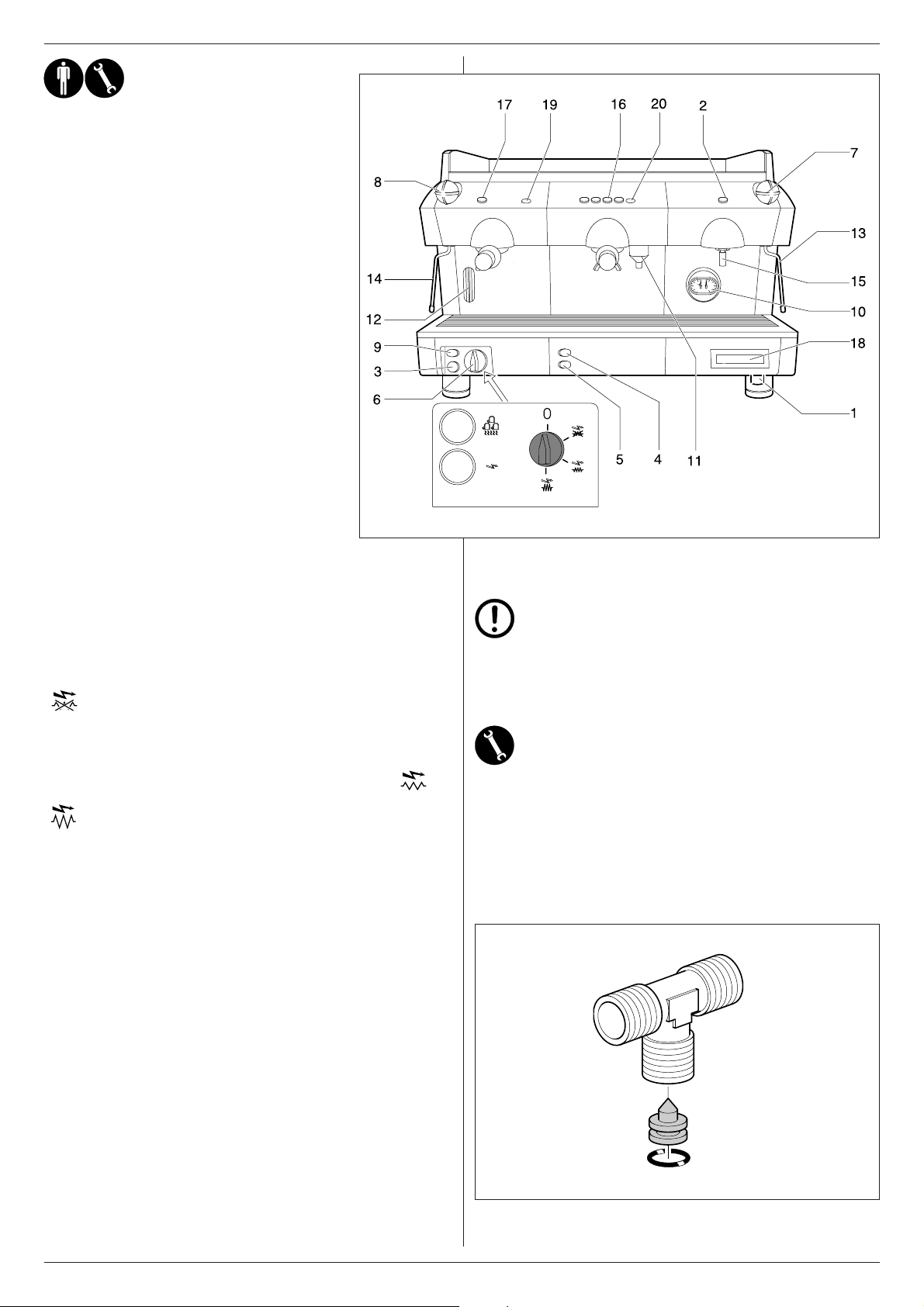
6 - MESSA IN
SERVIZIO
1 Rubinetto
2 Pulsante prelievo acqua calda
2 Interruttore prelievo acqua calda
3 Spia macchina in tensione
4 Valvola intercettazione gas
5 Accensione piezoelettrica
6 Interruttore generale
7 Rubinetto vaporizzatore destro
8 Rubinetto vaporizzatore sinistro
9 Interruttore scaldatazze
10 Manometro pressione caldaia/pompa
11 Cappuccinatore optional
12 Indicatore di livello caldaia
13 Tubo vaporizzatore sinistro
14 Tubo vaporizzatore destro
15 Tubo prelievo acqua calda
16 Tastiera comando gruppo D
17 Tasto comando gruppo E
18 Display contadosi optional
19 Spia erogazione E
20 Leed erogazione
ITALIANO
Fig.6.01
Ultimati i collegamenti idraulici, elettrici e del gas, si procede alla
messa in servizio della macchina.
Aprire il rubinetto della rete idrica (A).
Chiudere l’interruttore di protezione (D).
Portare l’interruttore generale macchina (6)sulla posizione
si accenderà la spia macchina in tensione (3).
L’autolivello si metterà in funzione affinchè l’acqua raggiunga il livello normale in caldaia. (12).
Portare l’interruttore generale (6) sulla posizione
per funzionamento a potenza normale o sulla posizione
per funzionamento a potenza massima, dando così
tensione alle resistenze.
Attendere quindi che la macchina raggiunga la pressione di esercizio 1,1 – 1,3 atm controllando sul manometro la pressione caldaia (10).
Qualora la macchina non si dovesse stabilire sui valori indicati, si
dovrà procedere alla taratura del pressostato come specificato al
paragrafo 6.2.
Quando la macchina è munita di riscaldamento a gas, dopo
l’azionamento dell’interruttore generale (6) si dovrà provvedere
all’accensione del gas azionando la valvola gas (4) premendo
l’accenditore piezoelettrico (5) finchè il gas non rimanga acceso.
IMPORTANTE:
Non premere il pulsante o l’interruttore prelievo acqua
calda (2) prima del raggiungimento della corretta pressione di esercizio 1,1¸atm indicate dal manometro caldaia (10).
6.1 GIGLEUR PER CAFFE’ LUNGHI
La macchina è dotata di gigleur (1 x gruppo) con passaggio Ø 0,6 mm
(Cod.26G0074/01).
Se si richiede una maggior velocità di erogazione del caffè, in caso di
caffè lunghi, nel corredo della macchina sono previsti n°2 gigleur (completi di guarnizione) con passaggio Ø 0,8 mm (Cod.26G0073/01).
Il gigleur è situato nel raccordo di alimentazione dello scambiatore
(1 x gruppo).
Controllare quindi la pressione sul manometro pompa (10) mettendo in funzione un gruppo con portafiltro inserito riempito di caffè regolarmente macinato, dosato e pressato per ottenere la reale
pressione di esercizio di 8/9 atm.
Nel caso necessitasse una eventuale ritaratura della pressione
pompa questa dovrà essere effettuata come specificato al paragrafo 6.3.
La macchina è ora pronta per l’uso.
Fig.6.02
12
Page 13
ITALIANO
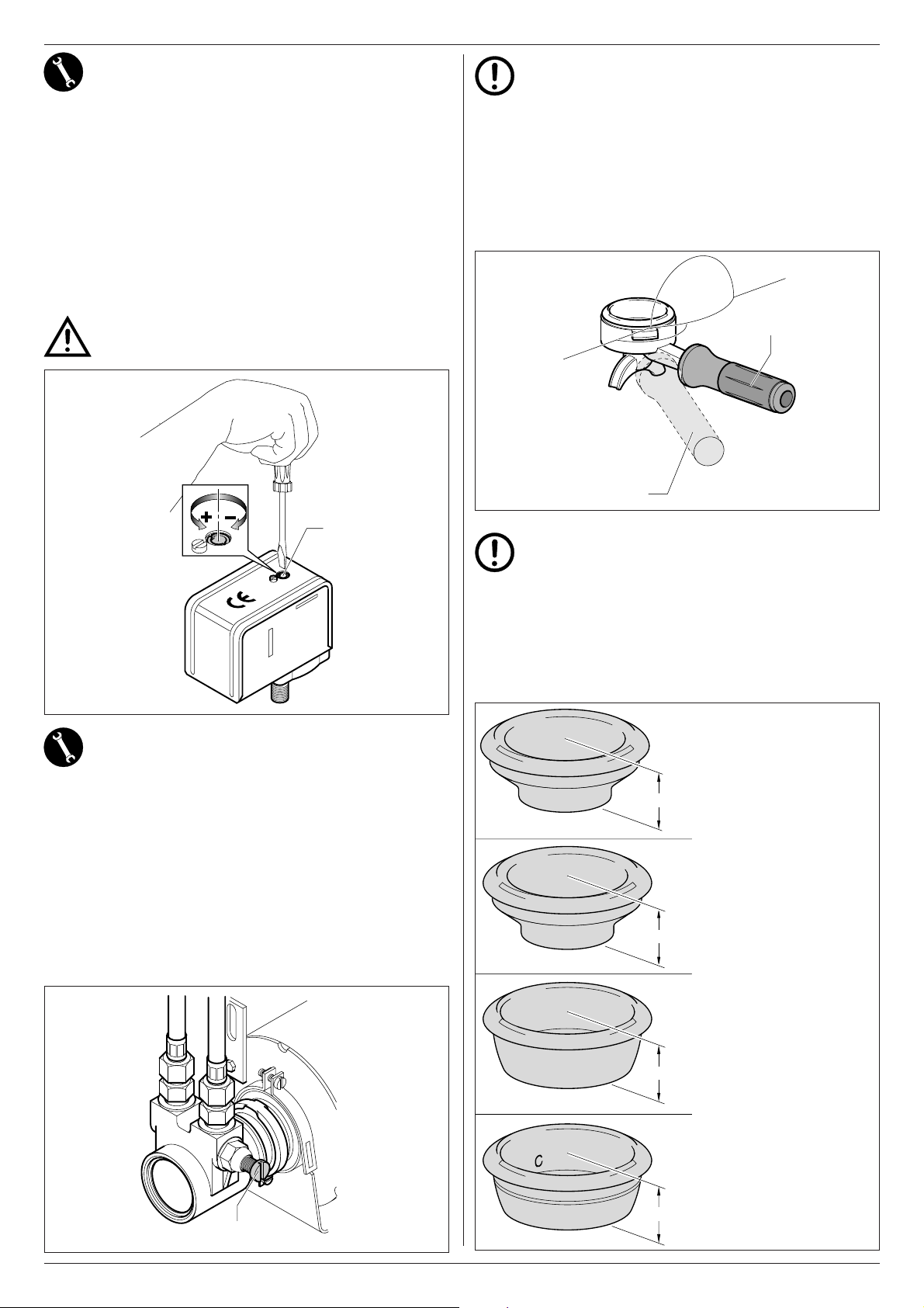
6.2 REGOLAZIONE DEL PRESSOSTATO
Il pressostato indicato nella figura ha la funzione di mantenere costante la pressione in caldaia inserendo o disinserendo la resistenza di riscaldamento elettrico.
Detto pressostato viene regolato già in fase di collaudo della macchina 1,1÷1,3 bar ma se il caso specifico richiedesse una diversa
pressione di esercizio, si può variare il campo d’azione del
pressostato agendo sulla vite i regolazione (U): diminuendo la pressione si ottiene una diminuzione della temperatura, viceversa, aumentando la pressione aumenta anche la temperatura dell’acqua.
Il senso di regolazione è indicato sulla figura e anche sul pressostato
stesso.
La pressione varia di circa 0,1 atm per ogni giro di vite completo.
Attenzione! Staccare l’alimentazione elettrica prima di effettuare questa operazione.
Attenzione!
Quando la macchina è nuova, la coppa portafiltro può risultare non allineata (perpendicolare alla macchina stessa) come indicato alla figura a fianco, senza per questo
compromettere il buon funzionamento della stessa.
Dopo un breve periodo d’utilizzo, la coppa andrà man mano
a posizionarsi nella posizione corretta.
A = Posizione del portafiltro chiuso con la macchina nuova
B = Posizione del portafiltro chiuso con la macchina dopo un
breve periodo d’uso
B
Fig.6.05
A
U
Fig.6.03
6.3 TARATURA PRESSIONE POMPA
Inserire nel gruppo il portafiltro riempito di caffè regolarmente macinato, dosato e pressato.Azionare l’interruttore gruppo (GE) o la
tastiera comando gruppo (GD) (16) e leggere la pressione sul
manometro pompa (10).
N.B. La giusta pressione è di 8/9 atm.
Se la pressione letta sul manometro non risultasse corretta, agire
sulla vite di regolazione pressione pompa (Z) girando in senso orario
per aumentare la pressione pompa, ed in senso antiorario per diminuire la pressione.
A regolazione avvenuta verificare la taratura della pompa erogando una o più dosi di caffè.
Z = Vite di regolazione pressione pompa
IMPORTANTE: A corredo sono inserite N°2 guarnizioni
sottocoppa di spessore inferiore (mm 8,1) a quella montata di serie. tali guarnizioni vanno usate qualora l’inserimento del portafiltro sia difficoltoso.
6.4 FILTRI CAFFÈ CORREDO MACCHINA
Secondo le quantità di cafe macinato occorre utilizzare il filtro come
sotto indicato per evitare che, ad erogazione terminata, la pastiglia
fondi caffè resti attaccata al gruppo erogatore.
NF08/002/B
1 Tazza 5,5 gr. ÷ 6,5 gr.
Cialda per 1 caffè
Cialda orzo per 1 dose
20 mm
NF08/004/B
1 Tazza 6 gr. ÷ 7 gr.
24,5 mm
Fig.6.04
NF08/005/B
2 Tazza 12 gr. ÷ 14 gr.
24,5 mm
NF08/009/B
Doppia Cialda per 2 caffè
Il Filtro e riconoscibile da
una lettera “C” stampata
21 mm
Z
Fig.6.06
13
all’interno
Page 14
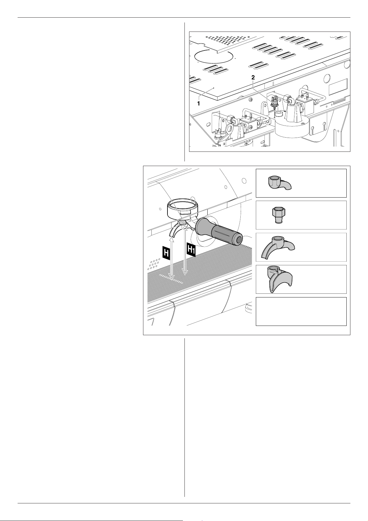
6.5 SOSTITUZIONE DEL TERMOSTATO PER
Cod. AS0146/CL
H = 85 mm
Cod. 26G0112
H = 95 mm
Cod. 6301004010
H = 100 mm
Cod. 6001023000
H = 92 mm
H1 = 120 mm
SENZA BECCUCCI
DIMINUIRE LA TEMPERATURA DEL
GRUPPO EROGAZIONE CAFFE’ (OPTIONAL)
Rimuovere la bacinella scaldatazze (1). Scollegare il termostato
del gruppo (2) (Cod.DM1561 - T 103°C) e sostituirlo con il termostato di temperatura più bassa (Cod.DM 1736 - T 98°C), inserito
nel corredo della macchina.
6.6 BECCUCCI A CORREDO
MACCHINA
ITALIANO
Fig.6.07
Vengono forniti a corredo della macchina N° 4
beccucci per ottenere erogazioni di caffè singole
o doppie.
Nella figura a fianco, vengono riportate le differenti distanze dalla griglia di appoggio caffè (H)
ottenibili in funzione delle diverse tipologie di
beccucci montati sul portafiltro.
Fig.6.08
14
Page 15
ITALIANO
7 - FUNZIONAMENTO / USO E
PROGRAMAZIONE
INTRODUZIONE
Attraverso il software di programmazione
si ha la possibilità di effettuare il controllo
delle seguenti operazioni:
- gestione di 2 – 3 - 4 gruppi caffè
- controllo di quattro differenti dosi di
caffè per ogni gruppo
- controllo della dose di tea (acqua
calda)
- funzionamento contemporaneo dei
gruppi caffè e del tea
- funzione cappuccino/latte
- controllo volumetrico delle dosi caffè
- controllo temporizzato dosi tea
- programmazione delle dosi in simulazione
- controllo e gestione livello riempimento
- supervisione del sistema attraverso
allarmi
- continuo, time out erogazione e altre
funzioni
- connessione seriale con dispositivi di
contabilizzazione
- display LCD 16 x 2 (non
retroilluminato) per la visualizzazione
degli stati funzionali
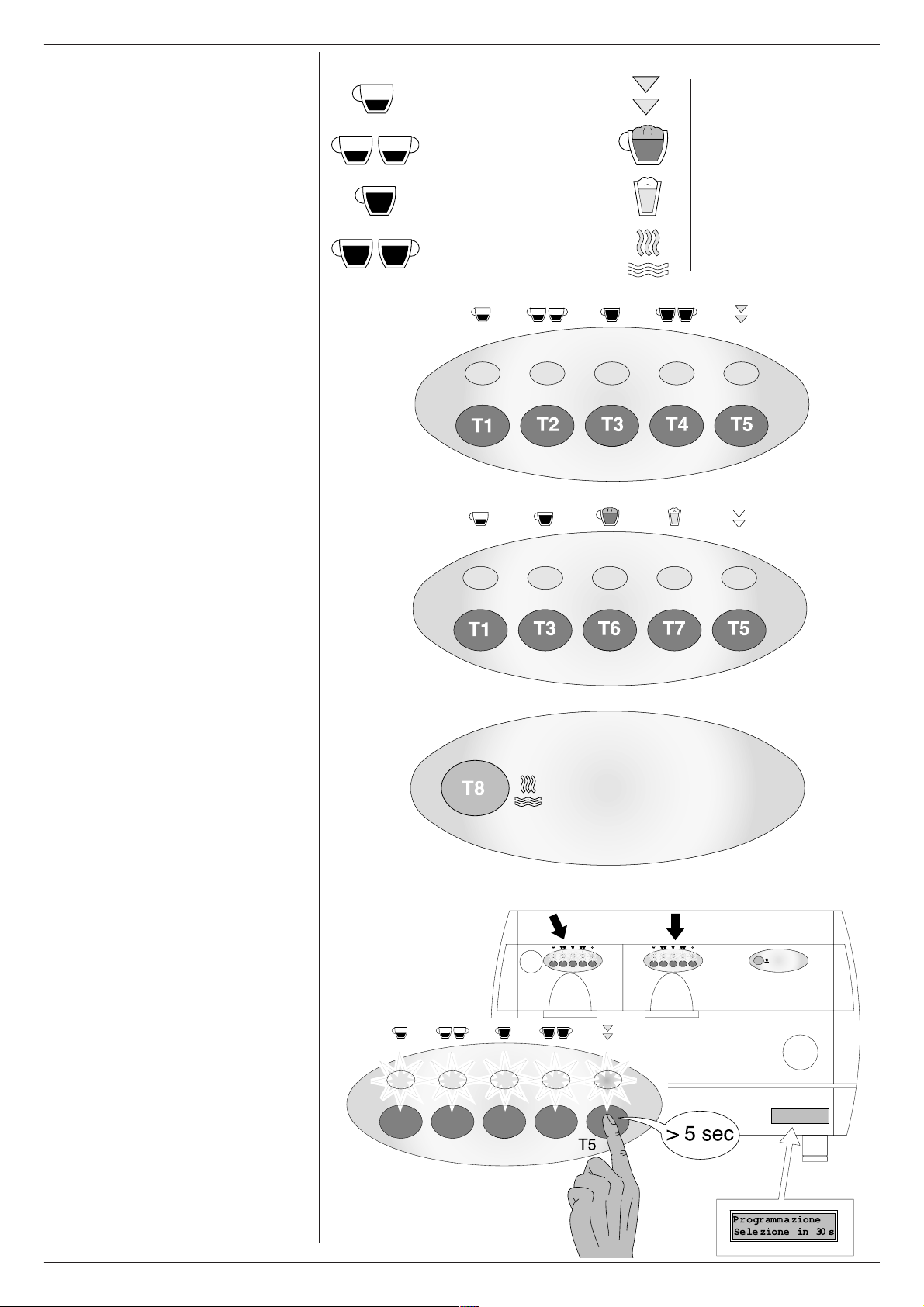
Simbologia della tastiera:
T1
Singolo caffè espresso
T2
Doppio caffè espresso
T3
Singolo caffè lungo
T4
Doppio caffè lungo
T5
Programmazione / Continuo
T6
Cappuccino
T7
Latte
T8
Tea (acqua calda)
Attenzione! Sul display viene sempre
visualizzata lultima selezione effettuata.
7.1 PROGRAMMAZIONE DOSE
CAFFÈ
E’ possibile modificare le quantità delle dosi
caffè (tramite controllo volumetrico) e memorizzarle seguendo questa procedura:
- premere il tasto T5 (della tastiera
relativa al gruppo 1) e mantenerlo
premuto per un tempo superiore a 5
secondi e verificare l’accensione di
tutti i led delle tastiere. In questo caso,
(agendo sulla tastiera relativa al
gruppo 1) si ottiene la programmazione di tutti i gruppi, mentre premendo il
testo T5 di un altro gruppo si ottiene la
programmazione del solo gruppo su
cui si sta operando.
ATTENZIONE! Le impostazioni effettuate
sul gruppo 1 (agendo sulla prima tastiera),
vengono copiate automaticamente anche
su tutti gli altri gruppi
.
15
Page 16
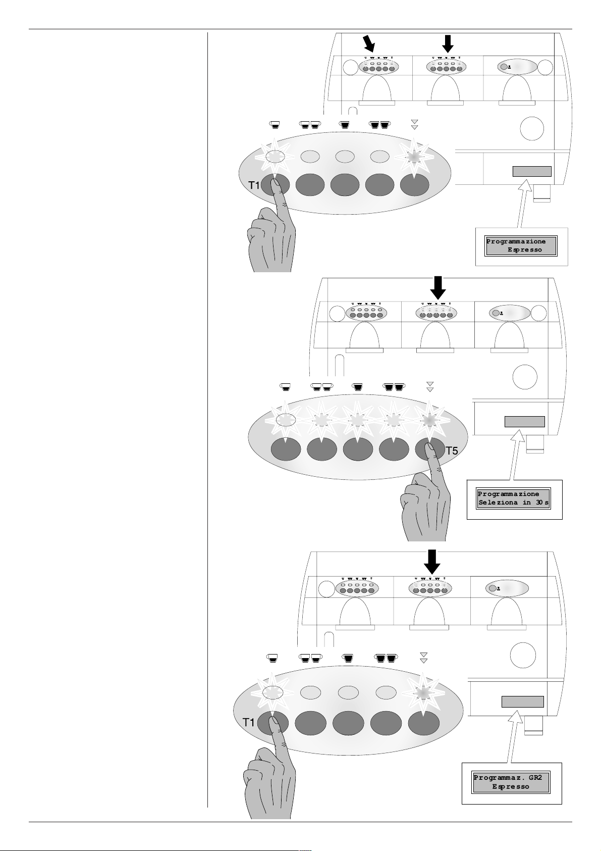
Entro 30 secondi (time out di programmazione), premere il tasto corrispondente alla
dose che si vuole programmare (ad esempio il tasto T1).
Il LED relativo al tasto T5 rimane acceso in
tutte le tastiere e inoltre si accende anche
il LED (su tutte le tastiere) relativo alla dose
che si sta programmando. In questa fase,
e per tutta la durata della programmazione
della dose caffè, viene attivata
l’elettrovalvola e la pompa.
Nota: se non viene premuto nessuno dei
tasti dose entro i 30 secondi, automaticamente si esce dallo stato di programmazione.
Dopo aver premuto il tasto T1, inizia
l’erogazione e, al raggiungimento della
dose di caffè desiderata, premere nuovamente il tasto T1 o uno qualsiasi degli altri
tasti della tastiera del gruppo che si sta programmando per interrompere l’erogazione
della dose di caffè. In questo modo viene
memorizzato sulla EPROM il nuovo valore
in impulsi della dose. Vengono disattivate
sia l’elettrovalvola che la pompa che interrompono l’erogazione del prodotto e vengono spenti tutti i led della tastiera.
ITALIANO
Per procedere ad una nuova programmazione delle altre dosi di caffè T2-T3-T4,
(qualora non si sia superato il tempo di timeout di programmazione di 30 sec) basta ripetere con la stessa sequenza le medesime operazioni effettuate per il tasto T1.
Per uscire immediatamente dalla fase di
programmazione ripremere il tasto T5.
ATTENZIONE! Qualora sia attiva la
funzione PREINFUSIONE (vedere al
par.7.5) la dosatura in fase di programmazione, abilita comunque questa funzione. Attendere quindi che la
preinfusione sia terminata prima di
arrestare lerogazione in corso.
NOTA: durante la programmazione di
un gruppo viene disabilitato il funzionamento degli altri gruppi e
lerogazione del tea.
Per programmare gli altri gruppi, premere
il tasto di programmazione specifico di ogni
gruppo e procedere con le stesse operazioni effettuate sul gruppo 1. In questo caso
le eventuali variazioni di dosatura sono rese
attive per il singolo gruppo su cui si sta operando.
16
Page 17

ITALIANO
7.2 PROGRAMMAZIONE DOSI
DEL TEA (ACQUA CALDA)
E’ possibile modificare le quantità
temporizzate relative alle dosi tea, seguendo la sequenza descritta:
Premere il tasto T5 del gruppo caffè 1 e
mantenerlo premuto per un tempo maggiore di 5 secondi e verificare l’accensione di
tutti i led delle tastiere.
Premere il tasto T8 Tea entro il tempo di 30
secondi (time-out programmazione).
In questo modo viene avviata l’erogazione
della dose di acqua tea.
Al raggiungimento della dose desiderata
premere nuovamente il tasto T8 per interrompere l’erogazione dell’acqua. Viene in
questo modo memorizzato il nuovo tempo
di erogazione dell’acqua Tea e tutti i led
delle tastiere vengono spenti.
Per uscire immediatamente dalla fase di
programmazione ripremere il tasto T5.
17
Page 18

7.3 EROGAZIONE CAFFE’
Premendo il tasto corrispondente, T1-T2T3 O T4, vengono attivate l’elettrovalvole
di erogazione corrispondenti per il tempo
necessario al raggiungimento della quantità di prodotto (controllo volumetrico) programmata precedentemente.
Il LED relativo al tasto della dose prescelta
rimane acceso per tutta la durata
dell’erogazione caffè.
E’ prevista la possibilità di interrompere
l’erogazione in corso prima del
raggiungimento della quantità di prodotto
programmato premendo uno qualsiasi dei
tasti dose presenti sulla tastiera del gruppo utilizzato per l’erogazione del prodotto.
E’ possibile ottenere l’erogazione contemporanea di caffè da tutti i gruppi della macchina.
ITALIANO
7.4 DOSE CAFFE’ IN CONTINUO
Per ottenere l’erogazione della dose di caffè in continuo premere il tasto T5 della
tastiera corrispondente al gruppo su cui si
vuole operare.
Il LED corrispondente al tasto T5 rimane
acceso per tutta la durata dell’erogazione.
IMPORTANTE! Fare attenzione a non
tenerlo premuto per oltre 5 secondi
perché in questo caso si accederebbe
alla modalità di programmazione.
L’erogazione del caffè continuerà fino ad
uno stop dose premendo il tasto T5, oppure al raggiungimento della quantità massima del prodotto ottenibile attraverso un controllo volumetrico (6000 impulsi) oppure
attraverso un Time-out di erogazione.
IMPORTANTE! Lo START relativo al
ciclo Continuo avviene al rilascio
(entro i 5 secondi) del tasto T5 e non
alla pressione dello stesso. Leventuale
STOP invece si ottiene premendo il tasto stesso una seconda volta.
18
Page 19

ITALIANO
7.5 FUNZIONI SPECIALI
E’ possibile attivare o disattivare alcune
funzioni speciali PRE_INFUSIONE, TEA
MISCELATO e ALLARME LAVAGGIO che
di seguito descriviamo:
ALLARME LAVAGGIO
PRE-INFUSIONE
Il nostro software consente di configurare
la dosatura in modo tale che l’erogazione
relativa alle dosi CAFFE’ a controllo
volumetrico sia preceduta dalla
preinfusione. L’erogazione della dose dopo
il tempo1 (ON) si interrompe per un tempo
2 (OFF) per poi riprendere a completare
l’erogazione della selezione.
Premendo uno dei tasti dose a controllo
volumetrico, il normale ciclo di erogazione
viene preceduto da un breve getto d’acqua
temporizzato utilizzato per inumidire la pastiglia di caffè prima del passaggio dell’effettiva erogazione.
Questa funzione permette un migliore sfruttamento della pastiglia caffè.
TEA (ACQUA CALDA)
MISCELATO
Se questa funzione è attiva si ha una
miscelazione dell’acqua erogata con l’acqua fredda in entrata nella caldaia ottenendo una erogazione costante ad una temperatura di circa 96°C.
Se questa funzione non è attiva
l’erogazione dell’acqua avviene ad una
temperatura di circa 100°C ed è molto vaporizzata.
Questa funzione fa in modo di indicare dopo
10 minuti dall’inizio dell’erogazione del cappuccino o del latte, la scritta “Run Milk
Clean” ed il lampeggio alternato dei LED
corrispondenti ai tasti T6 e T7 per indicare
che essendo stato effettuato un cappuccino o un latte, è necessario il lavaggio della
sezione latte.
Per azzerare temporaneamente l’allarme
premere il tasto T6 o T7.
LAVAGGIO DEL
CAPPUCCINATORE
Intervento da effettuarsi quando appare il
messaggio “Run Milk Clean” ed il lampeggio
alternato dei LED corrispondenti ai tasti T6
e T7.
Prendere un recipiente di 1 litro di acqua
fredda. Togliere il tubo di aspirazione del
latte dal contenitore e mettere lo stesso nel
recipiente.
Prendere contemporaneamente i tasti T7
e T5 (della tastiera attivata per le funzioni
“servizi”), in questo modo si attiva la funzione di erogazione latte, il passaggio dell’acqua pulirà il cappuccinatore.
Completata l’aspirazione dell’acqua, interrompere l’erogazione premendo il tasto T7.
L’operazione di lavaggio comunque
deve essere effettuata tutte le sere.
19
Page 20

ATTIVAZIONE /
DISATTIVAZIONE
Dare avvio alla macchina agendo sull’interruttore generale mantenendo premuto il tasto T5 del gruppo 1 ed attendere
l’accensione lampeggiante del Led relativo al tastoT5.
Agire sui tasti T1 – T2 e T3 ripettivamente
per attivare o disattivare le funzioni di
PRE_INFUSIONE, TEA MISCELATO e
ALLARME LAVAGGIO.
LED tasto T1 ACCESO: PRE-INFUSIONE: ON
LED tasto T2 ACCESO: TEA MISCELATO: ON
LED tasto T3 ACCESO: ALLARME LAVAGGIO: ON
Per uscire da questo stato e ritornare alle
normali funzioni premere nuovamente il
tasto T5
ITALIANO
7.6 EROGAZIONE TEA
Premendo il tasto T8 viene attivata
l’elettrovalvola corrispondente dando avvio
all’erogazione di acqua calda.
Al momento dello START, viene attivato un
Timer che una volta raggiunto il valore del
tempo impostato in fase di programmazione, interrompe l’erogazione dell’acqua.
E’ possibile ottenere l’erogazione contemporanea del Tea e del caffè
E’ prevista la possibilità di interrompere
l’erogazione in corso prima del
raggiungimento del tempo programmato
premendo nuovamente il tasto T8 utilizzato per l’erogazione del prodotto.
20
Page 21

ITALIANO
7.7 FUNZIONE CAPPUCCINO E
LATTE
E’ possibile impostare il funzionamento
CAPPUCCINO e LATTE sui tasti T6 e T7
sul gruppo 2 , 3 o 4 .
IMPORTANTE: La funzione è
impostabile solo su una tastiera per
volta, sul gruppo 2 o sul 3 o sul 4
.
ATTIVAZIONE/DISATTIVAZIONE
Per impostare la funzione per esempio sulla
tastiera del gruppo 2, tenere premuto in accensione il tato T5, il led corrispondente
lampeggia ed attendere fino a che il display
visualizzeràla scritta “SERVICE: OFF”.
Premere il tasto T1 della tastiera 2 per attivare la funzione Cappuccino/Latte sul “2°
gruppo
LED tasto T1 ACCESO: SERVICE: ON
Allo stesso modo procedere per abilitare
questa funzione sulla tastiera di un altro
gruppo.
21
Page 22

7.8 PROGRAMMAZIONE ED
EROGAZIONE CAPPUCCINO
Qualora la funzione sia attiva, il tasto T6
determina l’attivazione delle elettrovalvole
e della pompa per il valore impostato in programmazione.
Per la programmazione della funzione Cappuccino, procedere nel medesimo modo a
quanto fatto per il caffè con la differenza
che al termine dell’erogazione volumetrica
di caffè, INIZIA SEPARATAMENTE
l’erogazione a tempo del latte. Alla quantità desiderata, fermare l’erogazione attraverso il tasto T7.
ITALIANO
7.9 PROGRAMMAZIONE ED
EROGAZIONE LATTE
Quando la funzione è attiva, il tasto T7 determina l’attivazione dell’elettrovalvola per
il valore impostato in programmazione.
La programmazione di questa funzione è
la medesima dei quella del TEA.
22
Page 23

ITALIANO
7.10 ULTERIORI FUNZIONI PER
MACCHINA PROVVISTA DI
DISPLAY
SELEZIONE LINGUA
Per selezionare la lingua di consultazione,
al momento dell’accensione, premere e
mantenere premuto il tasto T4.
Premere poi più volte il tasto T1 fino a selezionare la lingua desiderata; premere nuovamente il tasto T4 per confermare la selezione.
23
Page 24

LETTURA CONSUMAZIONI
E’ possibile seguendo le indicazioni di seguito riportate, leggere le consumazioni
relative alle dosi di caffè effettuate.
Premere il tasto T5 (solo del 1° gruppo) e
mantenerlo premuto per un tempo maggiore di 10 secondi. Sul display vengono
visualizzate le erogazioni effettuate; per
uscire da questo stato premere nuovamente il tasto T5.
Premendo il tasto T1 (avanti) o T2 (indietro) si potranno interrogare le varie consumazioni memorizzate.
ITALIANO
Premendo il tasto T1 del gruppo 1 si passa
alle consumazioni dei tasti del gruppo 2 e
così via in successione.
24
Page 25

ITALIANO
Dopo aver visualizzato i dati anche dell’ultimo gruppo caffè premendo nuovamente
il tasto T1 alla verifica delle erogazioni effettuate di Tea.
Se si vuole azzerare i totali delle erogazioni
singole (ma non i dati “Cumulative total”)
effettuate, premere contemporaneamente
per 3 secondi i tasti T3 e T4 del gruppo 1
nello stato in cui viene visualizzato sul
display “CUMULATIVE TOTAL”
25
Page 26

7.11 SEGNALAZIONE DI
ALLARME
TIME OUT LIVELLO (RIEMPIMENTO) CALDAIA
Questo allarme viene segnalato qualora il
livello di acqua in caldaia diventa troppo
basso e la sonda di livello resta scoperta.
In questo stato i led delle tastiere
lampeggiano e sul display compare il messaggio di allarme.
Automaticamente viene abilitata la fase di
riempimento e per azzerare le condizioni
di allarme, togliere e ridare tensione alla
macchina.
ITALIANO
Assenza di impulsi del contatore
volumetrico
Dopo l’avvio di un ciclo caffè a controllo
volumetrico, viene verificato il corretto
funzionamento del contatore volumetrico
attraverso la rilevazione di impulsi inviati dallo stesso al microcontrollore.
Se non vengono rilevati impulsi per un
tempo maggiore di 5 secondi il LED relativo alla dose selezionata (ad esempio
il Led relativo al tasto T4) inizia a lampeggiare.
Dopo 1 minuto (Time-out contatore
volumetrico) di assenza impulsi, la dose
in corso viene arrestata automaticamente.
26
Page 27

ITALIANO
8 - RIGENERAZIONE DEPURATORE
A ENTRATA ACQUA
B USCITA ACQUA
C LEVETTA RUBINETTO ENTRATA
D LEVETTA RUBINETTO USCITA
E TUBETTO DEPRESSIONATORE
F TUBO RIGENERAZIONE
G POMOLO COPERCHIO
IMPORTANTE: Rigenerare il depuratore alle scadenze previste sotto indicate:
DUREZZA °F DEPURAT ORE TIPO 8 LITRI DEPURATORE TIPO 12 LITRI
Da 00 a 20 rigenerazione dopo 1100 l rigenerazione dopo 1600 l
Da 21 a 30 rigenerazione dopo 850 l rigenerazione dopo 1250 l
Da 31 a 40 rigenerazione dopo 650 l rigenerazione dopo 950 l
Da 41 a 50 rigenerazione dopo 450 l rigenerazione dopo 650 l
- Mettere il recipiente vuoto dalla capienza di circa 2 litri sotto il
tubetto E
- Spostare le levette C e D da sinistra verso destra come fig.
8.2 togliere il coperchio svitando il pomolo G, introdurre il
cloruro di sodio (sale da cucina di tipo grosso) in quantità di
kg 1,5 sul depuratore tipo 8 litri e di kg 2 sul depuratore tipo
12 litri).
- Rimettere il coperchio e riportare la levetta C da destra verso
sinistra come fig 8.3 lasciare scaricare l’acqua salata dal
tubetto F fino a che l’acqua sia dolce.
- Riportare la levetta D da destra verso sinistra come in fig 8.4.
NB. Le manovre per la rigenerazione, sono valide solo se il
depuratore è quello indicato sulle figure. Se non corrisponde, procedere come indicato nelle istruzioni allegate al
depuratore stesso.
27
Page 28

9 - REGOLAZIONE GAS
(p
)
)
)
)
4 Valvola intercettazione gas
5 Accensione piezoelettrica
N Regolatore gas
O Iniettore gas
P Ghiera
Q Vite di regolazione minimo
R Vite di regolazione pressione
ITALIANO
Fig.9.01
INIETTORE GAS
Categoria III 1a2H3+ macchina 2 GR macchina 3 GR macchina 4 GR
G20 (met ano
G30 (gas liquido
G110 (gas città
La macchina è predisposta per l’alimentazione con gas metano
(G20), cioè l’iniettore gas (O) ed il regolatore gas (N) sono tarati
per gas metano.
Per il funzionamento a gas GPL (gas liquido G30) o a gas città si
deve sostituire l’iniettore gas (O) con il corrispondente allegato alla
macchina (vedi tabella iniettori gas).
L’accensione del bruciatore gas deve essere effettuato tenendo
premuto il tasto della valvola intercettazione gas (4) per consentire
l’afflusso dell gas al bruciatore, quindi azionare il pulsante dell’accensione piezoelettrica (5).
B
03
1
os. O
C
04
2
Attendere che la caldaia raggiunga la pressione di esercizio
1,1÷1,3 atm e la fiamma sia ridotta al minimo. Se si rendesse
necessaria la taratura del regolatore gas (N) agire come segue:
ruotare in senso orario la vite regolazione minimo (Q) per abbassare l fiamma ed in senso antiorario per aumentare la fiamma.
Per aumentare o diminuire la pressione massima in caldaia, agire sulla vite di regolazione pressione (R) in senso orario per diminuire la pressione ed in senso antiorario per aumentarla.
D
05
3
NB. Il tasto della valvola di intercettazione deve rimanere
premuto per alcuni secondi affinché la termocoppia entri in
funzione.
Regolare il flusso dell’aria mediante l’apposita ghiera regolazione
aria (P) ruotando in senso orario diminuisce il flusso, in senso
antiorario aumenta in modo da ottenere una fiamma di colore azzurro (evitare fiamme lunghe o troppo ossidanti per non danneggiare la caldaia).
28
Page 29

ITALIANO
10 - MANUTENZIONE E CONSIGLI
UTILI
Per avere doccette (B) pulite e prive di depositi di polveri di caffè
che compromettono la resa, si consiglia prima di iniziare il lavoro
al mattino di inserire il portafiltro (D) con filtro cieco (a macchina
calda) ed azionare più volte il gruppo.
In questo modo si rimuovono polveri di caffè depositate tra doccetta
(B) e portadocetta (A).
Questa operazione dovrà essere effettuata tutti i giorni.
Controllare frequentemente i forellini dei filtri ( C ) per rimuovere
eventuali depositi.
Occorre inoltre dopo un lungo periodo di ristagno dell’acqua calda
nei conduttori, che si lasci scorrere un po’ d’acqua in caduta onde
rimuovere eventuali depositi.
Giornalmente è utile risciacquare i filtri ( C) e portafiltri (D) in acqua
A PORTADOCCETTA
B DOCCETTA
C FILTRO
D PORTAFILTRO
E GUARNIZIONE
F GRUPPO CAFFE’
G VITE CENTRALE
H VITI A BRUGOLA
calda meglio ancora lasciarli in acqua inizialmente calda per tutta
la notte, in modo da sciogliere i grassi di caffè.
Si consiglia di lasciare inserite le coppe portafiltro con i fondi di
caffè nel gruppo durante la giornata di lavoro per avere il portafiltro
sempre a temperatura ottimale.
Evitare di coprire il piano scaldatazze con tessuti, feltri ecc.
Per la pulizia della carrozzeria evitare di usare sostanze abrasive
o solventi.
Le lance vapore devono essere pulite subito dopo l’uso onde evitare he si formino incrostazioni che possono otturare i fori ed evitare inoltre che la bevanda riscaldata successivamente non prenda
cattivi sapori.
F
E
A
H
H
B
G
Fig.10.01
Operazioni di pulizia settimanale
Pulizia del gruppo e doccette: mettere un cucchiaino di polvere
detergente specifica per macchine da caffè nel filtro cieco in dotazione alla macchina e applicarlo al gruppo da pulire mediante il
portafiltro. Premere il pulsante di comando erogazione del gruppo
come per una normale erogazione di caffè. Dopo circa 30 secondi
interrompere l’erogazione e ripetere l’operazione per 3 / 4 volte:
Sciacquare il gruppo usando un filtro normale ed effettuare qualche erogazione di sola acqua. Fare un caffè per eliminare sapori
sgradevoli.
C
D
Sostituzione guarnizione sottocoppa
Si deve procedere alla sostituzione della guarnizione (E)
quando, fra il gruppo (F) e ed portafiltro (D), venga rilevata durante
l’erogazione una perdita di caffè o quando, chiudendo il portafiltro
(D), venga oltrepassato di molto il centro del gruppo.
Procedere quindi a togliere la doccetta (B) svitando la vite centrale
(G).
Togliere il portadoccetta (A) svitando le due viti a brugola (H).
Asportare quindi la guarnizione (E) aiutandosi con un cacciavite o
un punteruolo.
Dopo aver staccato la guarnizione provvedere a pulire la sede e
rimontare la nuova guarnizione facendo attenzione ad inserirla con
lo smusso rivolto in alto verso il gruppo.
29
Page 30

11 – RISOLUZIONE INCONVENIENTI
p
p
p
pomp
g
g
g
grupp
gg
p
q
g
p
g
g
p
pp
p
p
)
PROBLEMI CAUSA SOLUZIONE
La macchina non si accende 1. Interruttore rete spento 1. Portare l'interruttore generale in
osizione ON
2. Interrut tore mac china spento 2. Portare l'interruttore della macchina
sulla
3. Collegamento errato alla rete elettrica 3. Rivolgersi a personale specializzato
Manca l'acqua in caldaia 1. Rubinetto di rete chi uso 1. Aprire rubinetto di rete
2. Filtro della
3. Motopompa non funzionante 3. Rivolgersi a personale specializzato
Ero
azione gruppo assente 1. Rubinetto di rete chi uso 1. Aprire il rubinetto di rete
2. Motopompa non funzionante 2. Rivolgersi a personale specializzato
3. Gi
leur tappato 3. Rivolgersi a personale specializzato
4. Fusibile centralina bruciato 4. Rivol
5. Elettrovalvola gruppo non funzionante 5. Rivolgersi a personale specializzato
6. I nterrutt ore
Dalle lance non esce vapore 1. Troppa acqua in caldaia 1. Vedi probl ema specifico
2. Resistenza danne
3. S
ruzzatore intasato 3. Pulire lo spruzz at ore
4. Salvaresistenza disinserito 4. Reinserire la resistenza
Ac
ua in caldaia troppo alta 1. Il motore pompa rimane inserito 1. Rivolgersi a personale specializzato
2. Scambiatore forato 2. Rivol
3. Elettrovalvola carico automatico
bloccata
Perdite di acqua sul banco 1. Vaschetta scarico sporca 1. Pulire la vaschetta
2. Tubo di scarico intasato o staccato 2. Sostituire il tubo di scarico
3. Altre
Fondi del caffè ba
Erogazione del caffè troppo
lenta
Erogazione del caffè troppo
veloce
Caffè erogato freddo
Caffè erogato troppo caldo 1. Taratura pressostato errata 1. Regolare il pressostato agendo
nati 1. Macinatura regolata troppo fine 1. Regolare la macinatura
2. Gruppo ancora freddo 2. Aspettare che la macchina raggiunga
3. Elet trovalvola non sc arica 3. Rivol
1. Macinatura regolata troppo fine 1. Regolare la macinatura
2. Port afiltro sporco 2. Sostituire il filtro ed effettuare la
3. Gru
4. Gigleur o elettrovalvola parzialmente
intasati
1. Macinatura regolata troppo grossa 1. Regolare la macinatura
1. Pres enza di calcare sugli scambiatori o
sulla resistenza
2. Contatti del
3. Collegamento elettrico difettoso 3. Rivolgersi a personale specializzato
4. Resistenza
erdite 3. Rivolgersi a personale specializzato
o intasato 3. Rivolgersi a personale specializzato
a intasato 2. Sostituire il filtro
o non funzionante 6. Rivolgersi a personale specializzato
iata 2. Rivolgersi a personale specializzato
3. Rivolgersi a personale specializzato
la temperatura
4. Rivolgersi a personale specializzato
1. Rivolgersi a personale specializzato
ressostato ossidati 2. Rivolgersi a personale specializzato
arzialmente bruciata 4. Sostituire la resistenza
sull'apposita vite (cap.6.2
osizione 1
er la verifica del collegamento
ersi a personale specializzato
ersi a personale specializzato
ersi a personale specializzato
ulizia del portafiltro più frequentemente
ITALIANO
12 - SMANTELLAMENTO DELLA MACCHINA
Per lo smantellamento si consiglia di disassemblare la macchina
dividendone le parti secondo la loro natura (plastica, metallo ecc.).
Affidare poi a ditte specializzate nel settore le parti così suddivise.
30
Page 31

ENGLISH
ITALIANO 7 - 30
ENGLISH
31 - 54
DEUTSCH 55 - 78
FRANÇAIS 79 - 102
ESPAÑOL 103 - 126
INDEX
1 INSTRUCTIONS BOOKLET
CONSERVATION AND USE ......................... 32
2 ENVISAGED MACHINE USE ....................... 32
3 SAFETY ADVICE........................................... 33
4 TECHNICAL FEATURES .............................. 34
5 INSTALLATION .............................................. 35
5.1 WATER CONNECTION ......................... 35
5.2 ELECTRICAL CONNECTION ............... 35
5.3 GAS CONNECTION .............................. 35
6 START UP ................................................. 36
6.1 LONG COFFEE GIGLEUR ..................... 37
6.2 PRESSURE SWITCH ADJUSTMENT .... 37
6.3 PUMP PRESSURE CALIBRATION......... 37
6.4 FILTERS FOR COFFEE MACHINE ........ 37
6.5 REPLACEMENT OF THE THERMOSTAT TO
REDUCE THE COFFEE DISPENSING GROUP
TEMPERATURE ............................................ 38
6.6 WITH SPOUTS ....................................... 38
7 FUNCTION / USE AND PROGRAMMING ... 39
7.1 COFFEE MEASURE
PROGRAMMING ................................... 39
7.2 TEA MEASURE PROGRAMMING
(HOT WATER)......................................... 41
7.3 COFFEE DELIVERY .............................. 42
7.4 CONTINUOUS COFFEE MEASURES . 42
7.5 SPECIAL FUNCTIONS .......................... 43
7.6 TEA DELIVERY ...................................... 44
7.7 CAPPUCCINO AND MILK
FUNCTION ............................................. 45
7.8 CAPPUCCINO DELIVERY AND
PROGRAMMING ................................... 46
7.9 MILK PROGRAMMING
AND DELIVERY ..................................... 46
7.10 FURTHER FUNCTIONS ON MACHINES
EQUIPPED WITH DISPLAY................... 47
7.11 ALARM CONDITION.............................. 50
8 PURIFIER REGENERATION ........................ 51
9 GAS ADJUSTMENT ...................................... 52
10 MAINTENANCE AND USEFUL ADVICE ...... 53
11 TROUBLE SHOOTING ................................. 54
12 MACHINE DISMANTLING ............................ 54
31
Page 32

ENGLISH
1 - INSTRUCTIONS BOOKLET CONSERVATION
AND USE
The present instructions booklet has been prepared for the machine
user, the owner and the installation technician and must be always
available for reference purposes.
The manual is destined for the user, the maintenance technician
and machine installation technician.
The purpose of the instructions booklet is to indicate the envisaged
uses of the machine for which it has been designed, its technical
features and in order to provide advice on correct use, cleaning
and regulation. It also provides important maintenance information,
and details on any residual risks, and all those operations which
require particular care.
The present manual is to be considered as an integral part of the
machine and must be CONSERVED FOR FUTURE REFERENCE
until the final dismantling of the machine.
This instructions booklet must always be available for consultation
and must be kept in a protected and dry place.
In the event of loss or damage to the same, the user may ask the
manufacturer or local dealer for a new manual, indicating the
machine model and serial number of the same as indicated on the
identification plate.
2 - ENVISAGED MACHINE USE
The machine must be operated by a single operator only.
The authorized operator must have firstly read and fully understood
all the instructions contained in the present booklet to ensure correct
machine function.
This machine is specifically intended for the professional preparation
of espresso coffee using blended coffee, as well as the drawing
and delivery of water and/or steam.
Its components are made of resilient non toxic materials, and they
are easily accessible for cleaning or maintenance operations.
This machine is intended for internal use only.
Ambient temperature for the correct operation of the machine
5°C ÷ 40°C.
The present manual reflects the state of the art, at the time of its
preparation, the manufacturer however reserves the right to revise
production and subsequent manuals without being obliged to update
previous versions.
The manufacturer declines all responsibility in the event of :
- the improper or incorrect use of the coffee machine
- use that fails to comply with that specifically stated in the
present booklet
- serious lack of maintenance as envisaged or recommended
- machine modifications or any non-authorized intervention
- use of either non-original or non-specific spares
- total or partial failure to observe the instructions
32
Page 33

ENGLISH
3 - SAFETY ADVICE
The machine is to be used solely by adults who have carefully
read and fully understood this manual and all the safety advice
contained in the same.
The user is responsible in relation to third parties in the working
area.
The installer, user and maintenance technician are obliged to notify
the constructor of any defects or faults which may effect the original
safety of the system.
Installation must be effected solely by authorized and qualified
personnel.
The machine is to be used solely in the presence of suitable lighting.
For safety reasons, all worn or damaged parts must be promptly
replaced.
Regularly check that the power supply cable is in good conditions.
Damaged cables must never be repaired using insulating tape or
clamps.
Do not expose the machine to the elements (sun, rain , etc).
Prolonged machine standstill at temperatures of under 0°C (zero
degrees centigrade), may cause serious damage or breakage to
the boiler piping: it is therefore necessary to completely empty the
water circuit before every prolonged standstill.
Do not touch the coffee spouts and the hot water and steam nozzles
with your hands or any other parts of the body as the liquids or
steam issuing from them are very hot and may cause burns.
Avoid operating the machine without water.
Clogging may cause the generation of sudden liquid or steam jets
with serious consequences. Therefore keep the water as clean as
possible using filters and water softeners.
The cups and small coffee cups must be thoroughly dried before
placed on the relative surface.
The removal of guard and/or safety elements fitted on the machine
is forbidden.
The packaging components must be consigned to special disposal
centres and must in any event never be left unguarded or within
reach of children, animals or non-authorized persons.
The constructor declines responsibility for any damage to things,
persons or animals caused by eventual interventions on the
machine by personnel not specifically authorized to undertake such
operations.
In the event of any non-authorized interventions or repairs on the
machine, or in the event of the use of non-original spares all
guarantee terms become void, and the company reserves the right
to reject validity.
The user must comply with the current safety laws in force in the
country of installation, as well as common sense and ensure that
all maintenance operations are regularly carried out.
Never clean the inside of the machine with power supply on and
plug connected and in any event avoid the use of water sprays or
detergents.
The user must not touch the machine if his hands or feet are wet or
damp, neither must be use the machine in bare feet. Although the
machine is earthed it is advisable to use wooden platforms or a
cut-out box complying with local laws in order to prevent the risk of
electrocution.
33
Page 34

4 - TECHNICAL FEATURES
g
g
g
g
g
p
y
p
p
p
g
ENGLISH
H
Fig.4.01
B
2
roups3
Dimensions B 760 970 1180
H 500 500 500
L 540 540 540
ht k
Wei
Boiler ca
Boiler resistance absorbed power
ECO Max boiler resistance absorbed
acit
240 / 415 V 3 N ~ W 4760 5950 7140
230 / 400 V 3 N ~ W 4370 5465 6555
V 120 ~ W 4760 5950 7140
ower
240 / 415 V 3 N ~ W 3170 3950 4750
L 13 21 28
70 90 110
roups4
L
roups
230 / 400 V 3 N ~ W 2900 3640 4360
V 120 ~ W 3170 3950 4750
motor W 165 165 165
Pum
Overall absorbed
Gas heatin
ower
230-240/400-415 V 3 N ~ W 5200 6200 7200
Kcal/h 1700 2500 3400
34
Page 35

ENGLISH
5 - INSTALLATION
A. MAINS SUPPLY
B. DISCHARGE DUCTS
C. GAS DUCTS
D. PROTECTION SWITCH
E. PURIFIER
F. BOILER SUPPLY TAP
G. DRIP BOWL
H. GAS VALVE
I. POWER CABLE
Before proceeding with installation check that:
- there are no bumps, signs of knocks or deformities.
1 there are no damp patches or marks which could lead one to
assume that the packaging has been exposed to the
elements
2 there are no signs of tampering
Once one is satisfied that transportation has been correctly effected
proceed with installation.
Proceed with installation following the instructions according to the
sequence as described below.
5.1 WATER CONNECTION
Important: The machine must be supplied with water of
over 8°F hardness.
The installation of a water softener is recommended for the machine
water supply.
Check that the water mains to which connection is to be made
supplies drinking water.
- Connect purifier (E) to the water mains (A).
Fig.5.01
5.2 ELECTRICAL CONNECTION
Important ! Before proceeding with electrical connection
it is necessary to check to ensure that the voltage rating
corresponds with that indicated on the CE plate and on
the connection plate on the power supply cable.
Check to ensure that the electrical supply line is able to support the
machine load (see chap. 4 – technical features table).
Connect to an earthing socket which complies with current
legislation.
Check that the power supply cable is efficient and that it complies
with national and European safety standards.
The user must undertake to power the machine protecting the power
line using a suitable safety switch (cut-out) that complies with the
legislation in force in the actual country itself.
Connect the power cable (1) to the electric line using a plug, or in
the case of fixed installation, using a multi-polar switch (D) for mains
separation, with a contact distance of at least 3 mm.
For voltage change refer to the diagram shown on the general
mains switch box.
The yellow-green coloured cable MUST be connected to the room’s
earthing system.
NB: before connecting the purifier to the machine, wash
out thoroughly until the water becomes clear, then proceed
to connect the purifier to the machine.
- Connect the drain cup (G) to the drainage pipe (B)
- Should the mains pressure be higher than 5 bar a pressure
reducer balanced for high pressure should be installed
(device in which any mains pressure increase does not effect
the output pressure).
5.3 GAS CONNECTION
Connect valve (H) to duct (C) using a rubber hose (in compliance
with current standards) and suitable hose clamps or use the
connection supplied for stainless steel hose (as indicated in figure
in section 8 “Gas adjustment”.
35
Page 36

6 - START UP
1. Tap
2. Hot water outlet button
3. Hot water outlet switch
4. Machine on indicator
5. Gas on/off valve
6. Main switch
7. Right vaporiser tap
8. Left vaporiser tap
9. Cup-warmer switch
10. Boiler/pump pressure gauge
11. Optional cappuccino maker
12. Boiler level indicator
13. Left vaporiser tap
14. Right vaporiser tap
15. Hot water outlet pipe
16. Unit D control keyboard
17. Unit E control keyboard
18. Optional dose-counter display
19. E delivery indicator
20. D delivery led
ENGLISH
Fig.6.01
Once the water, gas and electrical connections have been made,
proceed to start up the machine.
Open the mains water supply tap (A).
Close the protection switch (D)
Position the machine main switch (8) to position the machine
on indicator will come on (3).
The auto-levelling device will come into operation so that the water
reaches a normal level in the boiler (12).
Position the main switch (6) to position for operation at normal
power or to position for operation at full power, thereby
powering the resistances.
Wait for the pressure to reach its operational pressure 1.1÷1.3 atm
checking the boiler pressure on the gauge (10).
Should the machine fail to stabilize on the indicated values it is
necessary to calibrate the pressure switch as described in
paragraph 6.2.
IMPORTANT
Do not press the hot water delivery switch or button (2)
before the correct working temperature of 1.1 atm is
reached, as indicated on the boiler gauge (10).
6.1 LONG COFFEE GIGLEUR
The machine is fitted with a gigleur ( 1 per unit) with a clearance of
0.6 mm (Cod.26G0074/01).
For greater coffee delivery speed, in the case of long coffees, no.2
gigleurs are also included with the machine (complete with seals)
with a clearance of 0.8 mm (Cod.26G0073/01).
The gigleur is located in the exchanger supply fitting (1 per group).
In the event of a machine featuring a gas heating system, it is
necessary to switch on the gas by operating the gas valve (4) after
operating the main switch (6), keeping the piezoelectric switch
pressed (5) until the gas remains on.
Then check the pressure on the pump gauge (10) putting a unit
into operation with filter holder engaged filled with ground, dosed
and pressed coffee in order to achieve an effective working pressure
of 8/9 atm.
Should re-calibration of the pump pressure be necessary this
operation should be undertaken as indicated in paragraph 6.3.
The machine is now ready for use.
Fig.6.02
36
Page 37

ENGLISH
6.2 PRESSURE SWITCH ADJUSTMENT
The pressure switch shown in the figure acts to keep the
boiler pressure constant by engaging or de-activating the electrical
heating resistance.
This pressure switch is already calibrated to 1.1-1.3 bar during the
initial machine testing stage, but should a different working pressure
be required, it is possible to vary the operational field of the pressure
switch using the regulation screw (U); pressure reduction results in
a reduction in temperature, whilst increasing the pressure will also
increase the water temperature.
The regulation direction is shown in the figure and on the pressure
switch itself.
The pressure varies by 0.1 atm for every complete screw turn,
Warning: Disconnect the electricity supply before
undertaking this operation.
Warning !!
When the machine is new the filter-holder sump may not be
aligned (perpendicular to the machine itself) as shown in
the figure at the side, however this does not effect the
efficient function of the same.
After a short period of use the sump will gradually settle
into a correct position.
A = Position of closed filter-holder with new machine.
B = Position of closed filter holder with machine after a short
period of use.
B
Fig.6.05
A
U
Fig.6.03
6.3 PUMP PRESSURE CALIBRATION
Insert the filter holder into the unit filled with regularly ground, dosed
and pressed coffee.
Switch on the unit switch or the unit control keyboard (16) and read
the pressure on the pump pressure gauge (10).
NB: The correct pressure is of 8-9 atm.
Should the pressure indicated on the pressure gauge be incorrect,
turn it clockwise to increase the pump pressure and anti-clockwise
to reduce the pressure.
Once adjustment is complete check pump calibration by delivering
one or more coffees.
Z= Pump pressure adjustment screw.
IMPORTANT: N°2 under-tile packings with are thinner
(8.1mm ) than that fitted as standard are included. These
packings may be used in the event of difficulty with insertion
of the filter holder.
6.4 FILTERS FOR COFFEE MACHINE
Depending on the quantity of coffee ground, the appropriate filter
must be as shown below to avoid that, once the coffee has dripped
out, the leftover powder remains attached to the nozzle.
NF08/002/B
1 coffee cup of 5,5 gr. ÷ 6,5 gr.
pod for 1 coffee
barley pod for 1 dose
20 mm
NF08/004/B
1 coffee cup of 6 gr. ÷ 7 gr.
24,5 mm
Fig.6.04
NF08/005/B
2 coffee cups of 12 gr. ÷ 14 gr.
24,5 mm
NF08/009/B
Double pod for 2 coffees
The filter may be recognised
Z
Fig.6.06
37
21 mm
by the letter “C” printed
inside
Page 38

6.5 REPLACEMENT OF THE THERMOSTAT TO
Cod. AS0146/CL
H = 85 mm
Cod. 26G0112
H = 95 mm
Cod. 6301004010
H = 100 mm
Cod. 6001023000
H = 92 mm
H1 = 120 mm
WITHOUT SPOUTS
REDUCE THE COFFEE DISPENSING
GROUP TEMPERATURE (OPTIONAL).
Remove cup heating bowl (1). Disconnect group thermostat (2)
(Code DM1561 – T 103°C) and replace it with the lower temperature thermostat (Code DM1736 – T 98°C), included in the machine
equipment.
6.6 SPOUTS INCLUDED IN THE
SUPPLY.
No. 4 spouts are supplied with the machine to
dispense one or two coffees.
ENGLISH
Fig.6.07
The figure (beside) shows the different distances
from the cup-holding tray (H), depending on the
different types of spouts fitted on the filter holder.
Fig.6.08
38
Page 39

ENGLISH
7 - FUNCTION / USE AND
PROGRAMMING
Keyboard symbols:
T1
Single espresso coffee
T5
Programming/continuos
INTRODUCTION
The programming software permits the
checking of the following operations:
- handling of 2-3-4 coffee units
- simultaneous function of both coffee
and tea units
- cappuccino/milk function
- volumetric check on coffee measures
- timed tea measure check
- simulated measure programming
- filling level check and control
- system supervision through alarms
- continuos, delivery time-out and
further functions
- serial connection with accounting
devices
- 16 X 2 LCD display (not rear-lit) for
functional state display.
Important: the last selection made always
appears on the display
T2
Double espresso coffee
T3
Single long coffee
T4
Double long coffee
T6
Cappuccino
T7
Milk
T8
Tea (hot water)
7.1 COFFEE MEASURE
PROGRAMMING
The measured amounts of coffee may be
modified (by means of volumetric checking)
and memorized as follows:
- press key T5 (of keyboard relative to
group 1) and keep pressed for over 5
seconds and check that all the
keyboard leds come on. In which case,
(by operating on the keyboard relative
to group 1) all the units will be
programmed, while by pressing key T5
of another unit, only the programming
of the unit on which one is operating is
possible.
IMPORTANT !! The settings made on unit
1 (operating on the first keyboard) will be
automatically copied on to all the other
units.
39
Page 40

Press the key corresponding to the
measure to be programmed (key T1 for
example) within 30 seconds (programming
time-out).
The led relative to T5 will remain on, on all
keyboards and the led relative to the
measure being programmed will also come
on (on all the keyboards). During this state
and for the entire coffee measure
programming time duration, the solenoid
valve and pump are activated.
Note: If none of the keys are pressed within
30 seconds, it will automatically escape
from programming mode.
On pressing key T1 coffee delivery begins,
once the required amount of coffee is
obtained press key T1 again or any other
of the keys of the unit keyboard in order to
suspend coffee delivery. The new impulse
value of the measure is thereby memorized
on the EPROM.
Both the solenoid valve and the pump are
de-activated thereby suspending product
delivery and all the keyboard leds go out.
ENGLISH
To proceed with a new programming
operation of other coffee measures T2-T3T4 (providing that the programming time
out time of 30 sec is not exceeded) simply
repeat the same operations with the same
sequence as undertaken for key T1.
Press key T5 to immediately escape from
the programming stage.
IMPORTANT: Should the “PRE-INFUSION”
function be active (see par. 7.5). Wait until
the pre-infusion function is complete before
stopping delivery in progress.
NOTE: During the programming of a unit
the function of the other units is deactivated
as well as tea dispensing.
To programme the other units, press the
specific programming key of each unit and
carry out the same operations as
undertaken on unit 1. In this case any
variations in the measures are activated
only on the unit on which one is actually
working.
40
Page 41

ENGLISH
7.2 TEA MEASURE
PROGRAMMING
(HOT WATER)
It is possible to modify the timed tea
measures according to the following
sequence:
Press key T5 of coffee unit 1 and keep
pressed down for over 5 seconds and check
that all the keyboard led indicators come
on.
Press the T8 tea key within 30 seconds
(programming time-out).
This begins the tea water delivery operation.
Once the required measure is obtained
press T8 again to suspend water delivery.
In this way the new tea water delivery time
is memory and all the keyboard leds go out.
Press key T5 again to immediately escape
from the programming phase.
41
Page 42

7.3 COFFEE DELIVERY
On pressing the corresponding key T1-T2T3 or T4, the corresponding delivery
solenoid valves are activated for the time
necessary to obtain the required amount
of product as previously programmed
(volumetric check).
The LED relative to the selected measure
remains on for the entire coffee delivery
time.
The delivery in progress may be suspended
before actually reaching the desired
programmed product quantity by pressing
any of the measure keys present on the
keyboard of the unit used for product
delivery.
It is also possible to obtain simultaneous
coffee delivery from all the machine units.
ENGLISH
7.4 CONTINUOUS COFFEE
MEASURES
For continuous coffee measure delivery
press key T5 from the keyboard
corresponding to the unit on which one
wishes to operate.
The LED corresponding to key T5 will
remain on for the entire delivery operation.
IMPORTANT ! Avoid keeping it pressed for
more than 5 seconds or it will enter the
programming mode.
Coffee delivery will continue until measure
stop by pressing key T5, or on obtaining
the maximum amount of product which can
be obtained through volumetric control
(6000 impulses) or by means of delivery
Time-out function.
IMPORTANT ! The start of the relative
“continuous” cycle occurs on the release
(within 5 seconds) of key T5 and not on
pressing of the same. While the STOP
function may be obtained by pressing it a
second time.
42
Page 43

ENGLISH
7.5 SPECIAL FUNCTIONS
It is possible to engage or deactivate certain
special functions such as PRE- INFUSION,
MIXED TEA and WASHING ALARM which
we shall describe below:
WASHING ALARM
PRE-INFUSION
Our software permits measure
configuration so that the relative delivery of
the COFFEE measures through volumetric
control is preceded by pre-infusion. Delivery
of the coffee measure after time 1 (ON) is
suspended for a time 2 (OFF) and is then
resumed for the completion of selection.
On pressing one of the volumetric control
measure keys, the normal delivery cycle is
preceded by a short timed water jet in order
to dampen the coffee pellets before actual
delivery stage.
This function ensures the optimum use of
the coffee pellets.
MIXED TEA (HOT WATER)
On the engagement of this function the
water delivered is mixed with cold water on
entry in the boiler thereby ensuring constant
delivery at a temperature of about 96°C.
If this function is not engaged water is
delivered at a temperature of about 100°C
and is highly vaporized.
This function acts to indicate, after 10
minutes from the start of the delivery of the
cappuccino or milk, the following signal
“Run Milk Clean” and the alternating
flashing of the LEDs corresponding to keys
T6 and T7 which indicate that a milk or cappuccino has been prepared and the milk
section therefore needs to be cleaned.
To temporarily cancel the alarm function
press key T6 or T7.
CAPPUCCINO MACHINE
CLEANING
Cleaning to be undertaken when the “Run
Milk Clean” message appears with the
alternating flashing of the LEDS
corresponding to keys T6 and T7.
Take a 1 litre container full of cold water.
Remove the milk suction pipe from the
container and place inside the container
itself.
Press keys T7 anf T5 at the same time (on
the keyboard activated for the “service”
functions) this engages the milk delivery
function, the water flow will clean the cappuccino machine.
Once all the water has been suctioned, stop
delivery by pressing key T7.
43
Page 44

ENGAGEMENT/DEACTIVATION
Start the machine by pressing the main
switch keeping key T5 of unit 1 pressed and
wait for the led relative to key T5 to begin
flashing.
Press keys T1-T2 and T3 in order to engage
or deactivate the PRE-INFUSION, MIXED
TEA and WASHING ALARM functions.
T1 KEY LED ON : PRE INFUSION: ON
T2 KEY LED ON : MIXED TEA: ON
T3 KEY LED ON : WASHING ALARM: ON
To escape from this condition and return to
normal functions press key T5 again.
ENGLISH
7.6 TEA DELIVERY
On pressing key T8 the corresponding
solenoid valve is engaged thereby
beginning hot water delivery.
On START a timer is activated which
interrupts the water delivery on reaching the
time set during the programming stage.
The simultaneous delivery of tea or coffee
is possible.
It is possible to interrupt delivery function
in progress before the programmed time is
reached by pressing key T8 again used for
product delivery.
44
Page 45

ENGLISH
7.7 CAPPUCCINO AND MILK
FUNCTION
It is possible to set the CAPPUCCINO and
MILK function on keys T6 and T7 on group
2,3, or 4.
IMPORTANT : The function can be set on
only one keyboard at a time, on unit 2, 3 or 4.
ENGAGEMENT/ DEACTIVATION
In order to set the function on the keyboard
of unit 2, for example, keep key T5 pressed
down and the corresponding LED will begin
flashing until the wording “SERVICE OFF”
appears on the display.
Press key T1 of keyboard 2 in order to
engage the Cappuccino/milk function on the
2nd unit.
T1 KEY LED ON : SERVICE: ON
Proceed in the same way to engage this
function on the keyboard of another unit.
45
Page 46

7.8 CAPPUCCINO DELIVERY
AND PROGRAMMING
When engaged key T6 will determine the
activation of the solenoid valve and pump
according to the value set during
programming.
To programme the cappuccino function,
proceed in the same way as for coffee with
the only difference being that at the end of
the volumetric delivery of the coffee, the
timed milk delivery BEGINS SEPARATELY.
Once the desired quantity is obtained stop
delivery using key T7.
ENGLISH
7.9 MILK PROGRAMMING
AND DELIVERY
Key T7 when engaged determines the
activation of the solenoid valve according
to the value set during programming.
The programming of this function is the
same as that for TEA.
46
Page 47

ENGLISH
7.10 FURTHER FUNCTIONS
ON MACHINES
EQUIPPED WITH DISPLAY
LANGAUGE SELECTION
In order to select the consultation language,
on switching on, press key T4 and keep
pressed.
Press key T1 several times to select the
desired language, press T4 again to confirm
selection.
47
Page 48

CONSUMPTION READING
It is possible to read the consumptions that
have been made following the instructions
indicated below.
Press key T5 (of 1st unit only) and keep
pressed for over 10 seconds. The display
will show the dispensing operations
undertaken : press key T5 again to escape
from this condition.
By pressing key T1 (forward) or T2 (back)
it is possible to consult the various
memorized consumption values.
ENGLISH
On pressing key T1 of unit 1 on goes on to
the consumption values of the keys of unit
2 and so on in succession.
48
Page 49

ENGLISH
After visualization of the data of the last
coffee unit also, on pressing key T1 it is
possible to obtain a reading of the number
of TEA dispensing operations made.
To cancel the totals of the individual
consumptions (but not the “total cumulative” data), press keys T3 and T4 of unit 1
for 3 seconds in the condition in which “CUMULATIVE TOTAL” is displayed.
49
Page 50

7.11 ALARM CONDITION
BOILER (FILLING) LEVEL TIME
OUT
This alarm condition occurs whenever the
water level is too low or the level probe
remains uncovered. In such a case the
keyboard leds flash and an alarm message
appears on the display.
The filling stage is automatically engaged
and to cancel the alarm conditions switch
the machine off and then on again.
ENGLISH
Lack of volumetric counter impulses
On starting a volumetric control coffee cycle,
the correct function of the volumetric
counter is checked by the reading of the
number of impulses sent by the same to
the micro-controller.
Should no impulses by recorded for a period
exceeding 5 seconds the LED relative to
the selected measure begins flashing (ie.
the led relative to key T4).
After one minute in which no impulses are
recorded (volumetric counter time out), the
measure underway is automatically
stopped.
50
Page 51

ENGLISH
8 - PURIFIER REGENERATION
A WATER INLET
B WATER OUTPUT
C INLET TAP LEVER
D OUTPUT TAP LEVER
E DEPRESSURIZER PIPE
F REGENERATION TUBE
G COVER KNOB
IMPORTANT : Regenerate the purifier at the intervals listed
below:
HARDNESS °F 8 LITRE PURIFIER 12 LITRE PURIFIER
From 00 to 20 regeneration after 1100 l. regeneration after 1600 l
From 21 to 30 regeneration after 850 l. regeneration after 1250 l.
From 31 to 40 regeneration after 650 l. regeneration after 950 l.
From 41 to 60 regeneration after 450 l. regeneration after 650 l.
- place the empty 2 litre container under pipe E.
- shift levers C and D from left to right as shown in fig.8.2 and
remove the cover by loosening knob G, pour in 1.5 kg of
sodium chloride (coarse cooking salt) into the 8-litre purifier
and 2 kg into the 12-litre type.
- Replace the lid and shift lever from right to left as shown in
fig.8.3 and allow the salted water to drain out of pipe F until
the water is fresh.
- Shift lever D from right to left as shown in fig.8.4
NB: These regeneration instructions are valid only
providing the purifier is as that indicated in the figures.
Should it fail to correspond proceed as indicated in the
instructions attached to the purifier itself.
51
Page 52

9 - GAS ADJUSTMENT
g
g
g
4 GAS- ON-OFF VALVE
5 PIEZOELECTRIC IGNITION
N GAS REGULATOR
O GAS INJECTOR
P RING NUT
Q MINIMUM ADJUSTMENT SCREW
R PRESSURE ADJUSTMENT SCREW
ENGLISH
Fig.9.01
GAS INJECTOR (pos.0)
Cate
ory III 1a2H3 + 2 GR machine 3 GR machine 4 GR machine
G20 (methane)
G30 (liquid
G11O (town
The machine is set up for being supplied with methane gas (G20),
this means that the gas injector (O) and the gas regulator (N) are
calibrated for methane gas.
For operation with GPL gas (liquid gas G30) or town gas, the gas
injector (O) must be replaced with the injector enclosed with the
machine (see gas injector table).
To light the gas burner keep the gas n-oiff valve button (4) pressed
down in order to allow the gas to flow to the burner, then operate
the piezoelectric ignition push-button (5).
NB: The on-off valve button must remain pressed down for
a few seconds to allow the thermo-couple to operate.
as)
as)
B
03
1
C
04
2
Wait for the boiler to reach an operating pressure of 1.1÷ 1.3 atm
and for the flame to be reduced to a minimum. If the gas regulator
(N) requires calibration, proceed as follows : turn the minimum
adjustment screw (Q) clockwise to reduce the flame and anticlockwise to increase it.
To increase or reduce maximum pressure in the boiler, turn the
pressure adjustment screw ® clockwise to decrease the pressure
and anti-clockwise to increase it.
D
05
3
Adjust the air flow by means of the air adjustment ring nut (P) turning
clockwise to reduce the flow and anti-clockwise to increase it, so
as to obtain a blue flame (avoid long or excessively oxidising flames
to avoid damaging the boiler).
52
Page 53

ENGLISH
10 - MAINTENANCE AND USEFUL
ADVICE
In order to ensure that the spouts (B) are kept clean and free of
any coffee deposits which may jeopardize yield, we advise that
before starting work in the morning that you put filter holder (D) in
with empty filter (while machine is hot) and operate the unit several
times.
In this way any coffee dust which may have been deposited between
the metal filter (B) and the metal filter holder (A) are removed. This
operation must be repeated every day.
Frequently check the filter holes (C) and remove any deposits.
Should the water have been left in the ducts for a long time, it is
necessary to allow some water to flow through them in order to
remove any deposits.
A SPOUT HOLDER
B SPOUT
C FILTER
D FILTER HOLDER
E SEAL
F UNIT COFFEE
G CENTRAL SCREW
H ALLEN SCREWS
It is a good idea to rinse the filters (C) and filter holders (D) every
day in hot water, or even better, place them in hot water and allow
to soak for the whole night in order to dissolve any greasy coffee
deposits.
It is advisable to leave the filter-holder cups inserted with the coffee
dregs for the entire working day to ensure that the filter-holder is
always at optimum temperature.
Do not cover the cup-warmer level with any fabrics or cloths etc.
Do not use any abrasive or corrosive products for cleaning the
bodywork.
The steam nozzles must be cleaned immediately after use in order
to prevent the risk of the formation of any scale which may block
the holes and to ensure that any drinks made subsequently do not
absorb any unpleasant odours.
F
E
A
H
H
B
G
Fig.10.01
Weekly cleaning operations
Cleaning of the unit and spouts: place a teaspoon of specific coffee
machine washing powder into the blind filter supplied with the
machine and apply to the unit to be cleaned using the filter-holder.
Press the unit delivery control button as for a normal coffee
dispensing operation. Suspend delivery after 30 seconds and then
repeat the operation 3-4 times. Rinse out the unit using a normal
filter and then undertake a few dispensing operations using water
only. Then prepare a coffee in order to eliminate any unpleasant
odours.
C
D
Below-cup seal replacement
Seal (E) needs to be replaced in the event that coffee leakage is
noted between unit (F) and filter-holder (G), or in the event that on
closing filter holder (D) the unit centre is greatly exceeded.
Remove the spout (B) by loosening the central screw (G).
Remove the spout holder (A) by loosening the two Allen screws
(H).
Then proceed to remove seal (E) using a screw driver.
After removing the seal undertake to clean the slot and then reassemble the new seal taking care to insert it with the chamfered
part turned upwards towards the unit itself.
53
Page 54

ENGLISH
p
p
p
p
pump
y
p
p
p
gg
gag
g
y
y
g
g
g
y
g
p
)
11 - TROUBLE SHOOTING
PROBLEM CAUSE REMEDY
Machine switch off 1. Mains switch off
2. Machine switch off
3. Incorrect electrical mains connection 3. contact s
No wat er in boiler 1. Mains tap clos ed 1. open the mains ta
2. Clogged pump filter 2. replace the filter
3. Motor driven
No unit deliver
Steam fails to come out of
the nozzle
Too much water in the boiler
Si
ns of water leakage on
bench
Wet coffee dre
Coffee dispensing too slow
Coffee dispensing too fast
Coffee delivered cold
Coffee delivered too hot 1. incorrec t pressure sw itch cali brati on 1. regulate the pressure switch by means
s 1. Grinding regulated too fine 1. Adjust grinding value
1. mains tap close d 1. open the mains ta
2. motor driven pump out of order 2. contact specialized personnel
3. clogged gigleur 3. contact specialized personnel
4. burnt control box fuse 4. contact s
5. unit solenoid valve out of order 5. contact specialized personnel
6. unit switch out of order 6. contact s
1. too much water in boiler 1. see specific probl em
2. damaged resistance 2. contact specialized personnel
3. clo
4. resistance saver en
1. the motor driven pump remains
engaged
2. perforated exchanger 2. contact specialized personnel
3. automatic charge solenoid valve
blocked
1. dirty drain tra
2. drainage pipe clogged or detached 2. replace the drainage pipe
3. other leakage 3. contact specialized personnel
2. Unit sti ll cold 2. wait for the machine to reach the
3. Solenoid valve fails to dischar
1. grinding element set too fine 1. Adjust the grinder
2. dirty filter-holder 2. replace the filter and undertake more
3. clogged unit 3. contact specialized personnel
4. gigleur or solenoid valve partiall
clogged
1. grinder i s regulated too large 1. regulate the grindin
1. Lime scale present on the exchangers
or the resistances
2. oxidized pressure switch contacts 2. contact specialized personnel
3. defective electrical connection 3. contact s
4. partially burnt out resistance 4. replace the resistance element
ed sprayer element 3. cl ean the sprayer element
not in operation 3. contact specialized personnel
ed 4. reinsert the resistance
e 3. contact specialized personnel
osition the machine switch to position ON
1.
2.
osition the machine switch to position 1
ecialized personnel in order
to check the connection
ecialized personnel
ecialized personnel
1. contact specialized personnel
3. contact specialized personnel
1. clean the tr
correct temperature
frequent filter-holder cleanin
4. contact specialized personnel
1. contact specialized personnel
ecialized personnel
of the relative screw (chap. 6.2
12 - MACHINE DISMANTLING
To dismantle the machine we recommend that it is dismantled and
the parts separated according to the type of materials involved
(plastic, metal, etc). The parts separated in this way are then to be
sent to the relative specialized disposal companies.
54
Page 55

LEGENDA COMPONENTI - COMPONENTS LIST - LEGENDE BAUTEILE
p
p
gung
p
p
p
gung
p
p
p
p
p
p
g
g
q
p
p
p
p
g
grup
g
É
q
p
g
É
p
p
g
É
p
pomp
pump
p
p
g
q
p
q
p
q
p
p
p
g
p
q
p
p
p
g
g
grupp
g
grup
p
y
p
g
g
g
q
g
g
g
q
p
q
p
q
p
p
g
play
y
y
É
y
LEGENDE DES COMPOSANTS- LEYENDA COMPONENTES
1Cavo alimentazione
entapolare
2Cavo alimentazione
tripolare
3Commutatore 4
osizioni
4 Pressostato tri
5Morsettiera di
derivazione
6 Resistenza caldaia boiler resistance Heizwiderstand Résistance de la
7Resistenza
scaldatazze
8 Termostato a riarmo
manuale
9Spia rossa macchina
accesa
10 Interruttore
scaldatazze
11 S
12 Interruttore caffè coffee switch Schalter Kaffee Interru
13 Elettrovalvola gruppo unit solenoid valve Magnetventil GruppeÉlectrovanne du
14 Elettrovalvola livello
15 Elettrovalvola
16 Elettrovalvola
17 Moto
18 Centralina controllo
19 Sonda livello
20 Interruttore
21 Interruttore
22 Resistenza a
23 Termostato
24 Relè
25 Tastiera dosatura
ia int erruttore
caffè
automatico
rel ievo acqua calda
relievo latte
livello automatico
automatico
ua calda
ac
ua calda
ac
cartuccia
relievo acqua
calda
volumetrica
olare three-pole pressure
a completa Complete motor
relievo
relievo
o unit thermostat Thermostat GruppeThermostat du
enta-polar power
cable
threecable
4commutator
switch
branch terminal board Verteilerklemmleiste Boîte de dérivation Tablero de bornes de
cu
resistance
manual re-set
thermostat
machine on - red light
indicator
cu
light indicator coffee
switch
automatic level
solenoid valve
Hot water collection
solenoid valve
Milk collection
solenoid valve
driven
automatic level
control box
automatic level
hot water collection
switch
hot water collection
switch
cartrid
hot water collection
rela
volumetric measurin
keyboard
ole power
osition
-warmer
warmer switch Schalter
e resistance Kartuschenwiderstand Résistance à
Fünfpoliges
Stromve rsor
bel
Dreipoliges
Stromve rsor
bel
4-stelliger
Umschalter
Dreipoliger
Druckwächter
Heizelement zur
Tassenerwärmun
Thermostat zur
manuellen
Rücksetzun
Rote Kontrolleuchte
Maschine in Betrieb
Tassenwärmer
Kont rol leuchte
Schalter Kaffee
Ma
netventil
automatischer
Füllstand
Ma
netventil
Heißwasserentnahme
Ma
netventil
Milchentnahme
Motorpumpe
lett
kom
Steuer
automatische
Füllstandkontrolle
robe Sonde automatischer
Füllstand
Scha l ter
Heißwasserentnahme
Scha l ter
Heißwasserentnahme
Relais
Heißwasserentnahme
Tas ta tur
Volumendosierun
ehäuse
Câble d'alimentation
ska-
ska-
entapolaire
Câble d'alimentation
tripolaire
Commutateur à 4
ositions
Pressostat tripolaire Presóstato tripolar
chaudière
Résistance du
chauffe-tasses
Thermostat à
réarmement manuel
Témoin rouge
machine allumée
Interrupteur du
chauffe-tasses
Témoin int errupteur
du café
teur du café Interruptor café
roupe
lectrovanne de
niveau automati
lectrovanne de
rél ève ment d'eau
chaude
lectrovanne de
rélèvement de lait
Pom
e complète Motobomba completa
Centrale contrôle
niveau automati
Sonde de niveau
automati
Interru
rél ève ment d'eau
chaude
Interru
rél ève ment d'eau
chaude
cartouche
roupe
Relais de
rél ève ment d'eau
chaude
Clavier de dosage
volumétri
ue
teur de
teur de
ue
Cable alimentación
entapolar
Cable alimentación
tripolar
Conmutador 4
osiciones
derivación
Resistencia caldera
Resistencia calientatazas
Termostato de
rearme manual
Luz de avi so roja
uina encendida
má
Interruptor calienta-
tazas
Luz de aviso
interru
Electroválvula
Electroválvula nivel
ue
automático
Electroválvula toma
de agua caliente
Electroválvula toma
de leche
Central control nivel
ue
automático
Sonda nivel
automático
Interru
ua caliente
a
Interru
ua caliente
a
Resistencia de
cartucho
Termostato
Relé toma de a
caliente
Teclado dosificación
volumétrica
tor café
o
tor toma de
tor toma de
o
ua
26 Centralina elettronica
dosatura volumet rica
27 Contatore
volumetrico
28 Pulsante
29 Dis
ac
ua calda
relievo
volumetric measurin
electronic control box
volumetric counter Volumenmesser Com
hot water collection
button
displa
Elektronisches
Steuergehäuse
Volumendosierun
Tas te
Heißwasserentnahme
Displa
Centrale électronique
du dosa
volumétri
volumétri
Bouton-
rél ève ment d'eau
chaude
cran Displa
e
teur
oussoir de
ue
ue
Central electrónica
dosificación
volumétrica
Contador volumétrico
Botón toma de a
caliente
ua
Page 56

GE-GD 2-3-4 GR.
CIRCUITO DI POTENZA - POWER CIRCUIT - LEISTUNGSKREIS CIRCUIT DE PUISSANCE - CIRCUITO DE POTENCIA
HIGH CURRENT SECTION OF THE ELECTRICAL CIRCUIT
Page 57

GE 2 GR.
CIRCUITO DI COMANDI - POWER DRIVES - STEUERUNGSYSTEM CIRCUIT DE COMMANDEMENT - CIRCUITO DE MANDO
CONTROL SECTION OF THE ELECTRICAL CIRCUIT
Page 58

GE 3 GR.
CIRCUITO DI COMANDI - POWER DRIVES - STEUERUNGSYSTEM CIRCUIT DE COMMANDEMENT - CIRCUITO DE MANDO
CONTROL SECTION OF THE ELECTRICAL CIRCUIT
Page 59

GE 4 GR.
CIRCUITO DI COMANDI - POWER DRIVES - STEUERUNGSYSTEM CIRCUIT DE COMMANDEMENT - CIRCUITO DE MANDO
CONTROL SECTION OF THE ELECTRICAL CIRCUIT
Page 60

GD 2 GR.
CIRCUITO DI COMANDI - POWER DRIVES - STEUERUNGSYSTEM CIRCUIT DE COMMANDEMENT - CIRCUITO DE MANDO
CONTROL SECTION OF THE ELECTRICAL CIRCUIT
Page 61

GD 3 GR.
CIRCUITO DI COMANDI - POWER DRIVES - STEUERUNGSYSTEMCIRCUIT DE COMMANDEMENT - CIRCUITO DE MANDO
CONTROL SECTION OF THE ELECTRICAL CIRCUIT
Page 62

GD 4 GR.
CIRCUITO DI COMANDI - POWER DRIVES - STEUERUNGSYSTEM CIRCUIT DE COMMANDEMENT - CIRCUITO DE MANDO
CONTROL SECTION OF THE ELECTRICAL CIRCUIT
Page 63

COLLEGAMENTO ELETTRICO - ELECTRICAL CONNECTION -
RACCORDEMENT ELECTRIQUE - STROMANCHLUSS - CONEXIÓN ELÉCTRICA
Prima d’effettuare l’allacciamento della machina alla rete elettrica, verificare il tipo di collegamento indicato sulla targhetta posta sul
cavo alimentazione. Normalmente le macchine sono predisposte per un collegamento a stella con neutro.
Before connecting the machine to the power point, make sure that the rating corresponds with the one indicated on the rating-plate of the
power cord. Normally, the machines are preset for a star connection with earthed centre point.
Bevor die Maschine an das Stromnetz angeschlossen wird, achten Sie auf die Art des Anschlusses, die auf dem Schild des
Versorgungskabels angegeben ist. Normalerweise ist bei den Maschinen eine Sternverbindung mit Nullleitung vorgesehen.
Avant d’effectuer le branchement de la machine au réseau électrique, vérifier le type de raccordement indiqué sur la plaquette placée
sur le câble d’alimentation. Normalement les machines sont prédisposées pour un raccordement en étoile avec neutre.
Antes de efectuar la conexión de la máquina con la red eléctrica, verifiquen el tipo de conexión indicado el la placa presente sobre el
cable de alimentación. Generalmente las máquinas están predispuestas para una conexión de estrella con neutro.
V 415 - 400 3N~
V 240 - 230 3~
Collegamento standard
Stella con neutro
Standard connection
Star connection with earthed centre
point
Standardanschluss
Stern mit Nullleiter
Raccordement standard
Etoile avec neutre
Conexión estándar
Estrella con neutro
Collegamento a triangolo.
Per modificare il collegamento da stella a triangolo
occorre intervenire sul cavo alimentazione, sulla
morsettiera alimentazione (A) e sulla morsettiera
di derivazione (B), modificando le connessioni indicate nello schema qui a fianco.
Delta Connection
To change the connection from a star connection to
a delta connection, modify the connections shown
in the diagram (beside) on the power cord, the input
terminal board (A), and the branching terminal
board (B).
Dreiecksanschluss.
Um einen Sternanschluss in einen
Dreiecksanschluss zu ändern, müssen auf dem
Versorgungskabel, dem Versorgungsklemmbrett
(A) und auf dem Abzweigungsklemmbrett (B) die
Anschlüsse geändert werden, die auf dem
nebenstehenden Schema gezeigt werden.
Raccordement en triangle
Pour modifier le raccordement d’étoile à triangle il faut intervenir sur le câble d’alimentation, sur la plaque à bornes alimentation (A)
et sur la plaque à bornes de dérivation (B), en modifiant les connexions indiquées dans le schéma ci-contre.
Conexión de triángulo.
Para modificar la conexión de estrella a triángulo, es necesario actuar en el cable de alimentación, en el tablero de bornes de
alimentación (A) y en el tablero de bornes de derivación (B), modificando las conexiones indicadas en el esquema al lado.
Page 64

Collegamento monofase.
V 240 - 230 ~
Per modificare il collegamento da stella a
monofase, occorre intervenire sul cavo alimentazione, sulla morsettiera alimentazione (A) e sulla
morsettiera di derivazione (B) ), modificando le
connessioni indicate nello schema qui a fianco.
Single-Phase Connection
To change the connection from a star connection
to a single-phase connection, modify the
connections shown in the diagram (beside) on
the power cord, the input terminal board (A), and
the branching terminal board (B).
Einphasenanschluss
Um einen Sternanschluss in einen
Einphasenanschluss zu ändern, müssen auf dem
Anschlusskabel, auf dem Versorgungsklemmbrett
(A) und auf dem Abzweigungsklemmbrett (B) die
Anschlüsse geändert werden, die auf dem
nebenstehenden Schema gezeigt werden.
Raccordement monophasé.
Pour modifier le raccordement d’étoile à monophasé il faut intervenir sur le câble d’alimentation, sur la plaque à bornes alimentation
(A) et sur la plaque à bornes de dérivation (B), en modifiant les connexions indiquées dans le schéma ci-contre.
Conexión monofásica.
Para modificar la conexión de estrella a monofásica, es necesario actuar en el cable de alimentación, en el tablero de bornes de
alimentación (A) y en el tablero de bornes de derivación (B) ), modificando las conexiones indicadas en el esquema al lado.
V 240 - 230 ~
Collegamento monofase con cavo alimentazione tripolare.
Per modificare il collegamento da trifase a stella
monofase, occorre cambiare il cavo di alimentazione e sostituirlo con un cavo tripolare tipo
HO7RN-F 3x4 mm
ne mercato USA). Intervenire sulla morsettiera
alimentazione (A) aggiungendo due ponticelli (C)
forniti con il materiale a corredo e modificare le
connessioni sia sulla morsettiera (A) che sulla
morsettiera (B) come indicato nello schema qui
a fianco.
2
(SJO 3x10 AWG per macchi-
Single-Phase Connection with Three-Core Power Cord
To change the connection from a three-phase connection to a single-phase star connection, change the power cord and replace it
with a three-core power cord of the HO7RN-F 3x4 mm2 type (SJO 3x10 AWG for machines used in the USA). Add the supplied two
jumpers (C) to the input terminal board (A) and modify the connections on the input terminal board (A) and on the branching terminal
board (B) as shown in the diagram (beside).
Einphasenanschluss mit Dreipolkabel.
Um einen Dreiphasenanschluss in einen Einphasensternanschluss zu ändern, muss das Versorgungskabel durch ein Dreiphasenkabel
HO7RN-F 3x4 mm
2
(SJO 3x10 AWG für Maschinen auf dem amerikanischen Markt) ausgetauscht werden. Auf dem
Versorgungsklemmbrett (A) zwei Brücken hinzufügen (C), die mitgeliefert werden und die Verbindungen sowohl auf dem Klemmbrett
(A) als auch auf dem Klemmbrett (B) ändern, wie es auf dem nebenstehenden Schema angezeigt wird.
Raccordement monophasé avec câble d’alimentation tripolaire.
Pour modifier le raccordement de triphasé à étoile monophasé, il faut changer le câble d’alimentation et le remplacer par un câble
tripolaire type HO7RN-F 3x4 mm
2
(SJO 3x10 AWG pour des machines marché USA). Intervenir sur la plaque à bornes d’alimentation
(A) en ajoutant deux ponts (C) fournis avec le matériel en dotation et modifier les connexions à la fois sur la plaque à bornes (A) et
sur la plaque à bornes (B) comme indiqué dans le schéma ci-contre.
Conexión monofásica con cable de alimentación tripolar.
Para modificar la conexión de trifásica a estrella monofásica, es necesario cambiar el cable de alimentación y sustituirlo con un cable
tripolar de tipo HO7RN-F 3x4 mm2 (SJO 3x10 AWG para las máquinas destinadas al mercado de los EE.UU.). Actúen en el tablero de
bornes de alimentación (A) añadiendo dos conectores puente (C) suministrados junto con el material en dotación, y modifiquen las
conexiones tanto en el tablero de bornes (A) como en el tablero de bornes (B) según lo indicado en el esquema al lado.
Page 65

Allegato 1
COMUNICAZIONE AI SENSI DELL’ARTICOLO 19, COMMA 3 DEL D. LGS. 93/2000
(luogo e data)
Spettabile:
Con la presente, il sottoscritto legale rappresentante
della società: situata:
(Nome e ragione sociale della ditta) (Indirizzo, città e CAP)
comunica la messa in servizio della seguente macchina per caffè espresso:
Gaggia s.p.a.
(marca)
(tipo)
(N° fabbrica)
In fede
(firma del legale rappresentante)
ONLY FOR ITALY
DM2189
Page 66

Page 67

Dipartimenti e compentenze territoriali
ISPESL ORGANIZZAZIONE PERIFERICA
081/7640857 NA; AV; BN; CE; SA
081/7645868
081/411509
081/421242
081/421593
Via Lomonaco, 3
Allegato 2
DM2190
CAP CITTA’ INDIRIZZO TELEFONO FAX DIPART. TERRITORIALI
15100 Alessandria Via C. Lombroso,14 0331/252653 0131/262730 AL; AT
60100 Ancona Via Cadorna, 10 071/201855 071/201041 AN; AP; PS; MC
70122 Bari Via Piccinni, 164 080/5237363 08075244049 BA; FG
24100 Bergamo Via G. Paglia, 40 035/244164 035/239214 BG
13051 Biella Via V. Cerreti, 7 015/8494919 015/8494989 AO; NO; VO
40121 Bologna Via C. Boldrini, 14 051/254310 051/254450 BO; FE; MO
39100 Bolzano Via Orazio, 49 0471/272222 0471/283728 BZ; TN
25100 Brescia C.so Cavour, 15 030/294801 030/294801 BS; CR; MN
09100 Cagliari Via Malta, 45 070/651236 070/659235 CA; OR
86100 Campobasso Via N. Sauro, 6 0874/698045 0874/698045 CB; IS
95129 Catania L.go dei Vespri, 19 095/316080 095/916595 CT; ME; EN; RG; SR;
88100 Catanzaro Via F. Spasari, 3 0961/741082 0961/701499 CZ; CS; RC; KR
22100 Como V.le G. Cesare, 17 031/265266 031/260047 CO; SO; VA
50121 Firenze Via G. La Pira, 17 055/289681 055/210882 FI; AR; SI
47100 Forlì P.le della Vittoria, 12 0543/63325 0543/401415 FO; RA
16122 Genova P.zza Brignole, 3 010/566441-2-3 010/528786 GE; IM; SP; SV
57100 Livorno Via Grande, 129 0586/884624 0586/896913 LI; GR; PI
55100 Lucca Via Buonamici, 9 0583/418803 0583/418300 LU; MS; PT
20133 Milano Via Mangiagalli, 3 02/2360351 02/70636032 MI; PV
80121 Napoli Via Chiatamone, 33
35100 Padova Via Berchet, 9 049/651263 049/658641 PD; RO; VI
90139 Palermo Via F. Crispi, 108 091/331696 091/332709 PA; AG; CL; TP
65100 Pescara C.so V. Emanuele II, 10 085/4212024 085/4210486 PE; CH; AQ; TE
29100 Piacenza Via Taverna, 273 0523/40084 0523/499679 PC; PR; RE
85100 Potenza Via Pretoria, 108 0971/37061 0971/35069 PT; MT
00186 Roma Via Bargoni, 8 06/58330651-2-3 06/58330680 RM; FR; LT; RI; VT
07100 Sassari Via Amendola, 82 079/217172 079/217392 SS,NU
74100 Taranto Via D’acquino, 40 099/4525025 099/4525026 TA; BR; LE
05100 Terni Via della Rinascita, 10 0774/402078 0774/420171 TR; PG
10128 Torino C.so Turati, 11 011/502727 011/503826 TO; CN
33100 Udine V.le Ungheria, 32 0432/501669 0432/504187 UD; GO; PN; TS
30172 Venezia/Mestre C.so del Popolo, 133 041/980121 041/5040189 VE; BL; TV
37100 Verona Via L. Poloni, 7 045/8007071 045/594199 VR
Page 68

/)//1) S.p.A.
20087 Robecco sul Naviglio - MI - Italia
Tel. +039 02 94 99 31
Fax +039 02 94 70 888
Internet: www.gaggia.it
E-mail: gaggia@gaggia.it
COD. 4001115000 - REV. 04
 Loading...