

Page 1
Operation, Maintenance and Installation Manual
KG 291 CA
Gas Cooktop
Page 2

1
FOR YOUR SAFETY Page 2
1. Important Information for Installation and Use Page 3
2. General Safety Instructions Page 4-5
3. Important Notes Page 6-7
For Your Safety Page 6
Operating for the First Time Page 6
To Use Page 7
4. Features Page 8
Features of the Appliance Page 8
Control Knob Page 8
Burner Parts Page 8
5. Operating Principle Page 9
6. Operation Page 10-11
7. Burner Settings Chart Page 12
8. Cookware Recommendations Page 13
9. Wok Cookware Recommendations Page 14
10. Cleaning and Care Page 15-17
11. Maintenance Page 18
12. Trouble Shooting Page 19
13. Technical Data/ Settings Table Page 20-21
14. Installation Instructions Page 22-29
Important Notes Page 22
Cabinet Requirements Page 23
Electrical Connection Page 24
Gas Connection Page 25
Nozzle Replacement Page 26-28
Installing the Appliance Page 29
KG 291 CA
Page 3
FOR YOUR SAFETY
2
WARNING: If the information in this
manual is not followed exactly, a fire or
explosion may result causing property
damage, personal injury or death.
Do not store or use gasoline or other
flammable vapors and liquids in the
vicinity of this or any other appliance.
WHAT TO DO IF YOU SMELL GAS:
– Do not try to light any appliance.
– Do not touch any electrical switch;
do not use any phone in your building.
– Immediately call your gas supplier
from a neighbor’s phone. Follow the
gas supplier’s instructions.
– If you cannot reach your gas supplier,
call the fire department.
Installation and service must be
performed by a qualified installer,
service agency or the gas supplier.
Page 4

1. Do not allow the flame to extend beyond the
edge of the cooking utensil. This instruction is
based on safety considerations.
2. Do not forget that the unit becomes hot when in
use. Common sense is important. Just because
the flame is out, it does not mean parts still
cannot be hot.
3. This appliance shall not be used for space
heating. This instruction is based on safety
considerations.
4. Be sure to disconnect the electrical supply
before disassembly of the appliance.
5. Keep the appliance area clear and free from
combustible materials, gasoline and other
flammable vapors and liquids.
6. Do not obstruct the flow of combustion and
ventilation air.
7. Cabinets installed above the gas cooktop must
have a minimum distance of 762 mm (30 ´ ´ ).
8. The gas pressure regulator supplied with the
appliance must be installed in line with the gas
pipe.
9. The appliance and its individual shutoff valve
must be disconnected from the gas supply
piping system during any pressure testing of the
system at test pressures in excess of 3.5 kPa
(1/2 psig). The appliance must be isolated from
the gas supply piping system by closing its
individual manual shutoff valve during any
pressure testing of the gas supply piping system
at test pressures equal to or less than 3.5 kPa
(1/2 psig).
10.
Important:
When using a very large pot, keep a distance of
at least 50 mm (2") to avoid damaging any parts
in counter top wood, plastic or other non-heatresistant materials. Never leave oil or hot fat
unattended.
Note: To avoid jeopardising the electrical safety of
the appliance, it is forbidden to use high-pressure
or steam jet cleaning devices.
Note: The name plate is attached to the bottom of
the unit and to the inside of the housing.
Only for Installation in USA:
This installation must conform with local codes or, in
absence of local codes, with the National Fuel Gas
Code, ANSI Z 223.1 Current Issue.
The installer must leave these instructions with the
appliance, and the consumer should keep them for
future reference. If an external electrical source is
utilized, the appliance must be electrically
grounded in accordance with local codes, with the
National Electrical Code ANSI/NFPA 70 Current
Issue.
For Massachusetts Installations:
1. Installation must be performed by a qualified or
licensed contractor, plumber or gas fitter
qualified or licensed by the state, province or
region where this appliance is being installed.
2. Shut-off valve must be a “T" handle gas cock.
3. Flexible gas connector must not be longer than
36 inches.
Only for Installation in Canada:
In Canada, installation must be in accordance with
the CAN 1-B149.1 and .2 – Installation Codes for
Gas Burning Appliances and/or local codes. The
installer must leave these Instructions with the
appliance and the Consumer should retain them for
future reference.
This appliance when installed, must be electrically
grounded in accordance with local codes or, in the
absence of local codes, with the current CSA
Standard C 22.1-Canadian Electrical Code, Part I.
For mobile Housing and Recreational Vehicle
installation must conform with the following:
CAN/CSA Z240 MH
CAN/CSA Z240 RV
Installation Requirement For Gas Burning
Appliances And Equipment In Mobile Homes CSA
Standard C 22:1 - Canadian Electrical Code Part 1
and /or local Codes.
1. Important Information for Installation and Use
3
Page 5

Read all instructions in this Operation and
Maintenance Manual carefully before using
your new GAGGENAU Cooktop.
As the user, you
are responsible for maintenance and proper use in
the household.
WARNING: These precautions will reduce the
risk of burns, electric shock, fire, and injury to
persons. Use extreme care when using this
cooktop as this appliance provides intense
heat and can increase the accident potential.
When using kitchen appliances, these basic
safety precautions must be followed:
• Insure proper installation and servicing.
Follow the installation instructions provided with
this product. Have the cooktop installed and
grounded by a qualified technician.
Do not
operate the appliance if it is damaged.
• Have the installer show you where the gas
supply shut-off valve is located
so that you
know how and where to turn off the gas to the
cooktop.
• If you smell gas, follow the instructions on
page 2. If the connections are not perfectly tight,
you can have a small leak and therefore a faint
gas smell. Finding a gas leak must be done by a
qualified service technician.
• Do not repair or replace any part of the
appliance
unless specifically recommended in
this manual. All other servicing should be referred
to a qualified technician. Disconnect the
appliance from the power supply at the fuse point
and the gas supply during every maintenance
operation.
• Children should not be left alone or
unattended in an area where appliances are
in use.
They should never be allowed to sit or
stand on any part of the appliance.
• Do not store items of interest to children
above the cooktop or at the back of it.
If
children should climb onto the appliance to reach
these items, they could be seriously injured.
• Never use any part of the cooktop for
storage.
Flammable materials can catch fire and
plastic items may melt or ignite.
• When connecting electrical appliances near
the Cooktop, make sure that connecting cables do
not come into contact with hot cooking surfaces!
• If the cooktop is near a window, be certain the
curtains do not blow over or near the Cooktop
burners; they could catch on fire.
• DO NOT USE WATER ON GREASE FIRES.
Turn appliance off and smother fire with baking
soda or use a dry chemical or foam-type
extinguisher.
• Never let clothing, pot holders, or other
flammable materials come in contact with or
close to any burner or burner grate
until it has
cooled. Fabric may ignite and result in personal
injury.
• Use only dry pot holders. Moist or damp pot
holders on hot surfaces may cause burns from
steam. Do not use a towel or other bulky cloth in
place of pot holders. Do not let pot holders touch
hot burner grates.
• For personal safety, wear proper apparel.
Loose fitting garments or hanging sleeves should
never be worn while using this appliance. Some
synthetic fabrics are highly flammable and should
not be worn while cooking.
• The appliance is designed for cooking food.
Based on safety considerations, never use the
Cooktop to warm or heat a room. Such use can
damage the Cooktop.
• When using the Cooktop: DO NOT TOUCH THE
BURNER GRATES OR THE IMMEDIATE
SURROUNDING AREAS.
They become hot
enough to cause burns.
2. General Safety Instructions
4
Page 6

• Never leave the cooktop unattended.
Boil-overs cause smoking and greasy spills that
may ignite.
•
Only certain types of glass, heatproof glass-
ceramic, ceramic, earthenware or other
glazed utensils are suitable for cooktop use.
This type of utensil may break with sudden
temperature changes. Use only on low or medium
heat settings according to the utensil
manufacturer’s directions.
•
Do not heat unopened food containers; a
buildup of pressure may cause the container to
burst.
• During cooking,
set the burner control so that
the flame heats only the bottom of the pan
and does not extend beyond the bottom of the
pan.
• Use caution to insure that drafts like those from
forced air vents or fans do not blow flammable
material toward the flames or push the flames so
that they extend beyond the edges of the pot.
•
Always use utensils that have flat bottoms,
large enough to cover the burner.
The use of
undersized utensils can expose a portion of the
flame and may result in ignition of clothing.
• To minimize burns, ignition of flammable materials
and unintentional spills,
position handles of
utensils inward
so they do not extend over
adjacent work areas, cooking areas or the edge of
the cooktop.
•
Hold the handle of the pan to prevent
movement of the utensil when stirring or turning
food.
•
GREASE IS FLAMMABLE. Let hot grease cool
before attempting to handle it. Avoid letting
grease deposits collect. Clean after each use.
• For proper lighting and performance of the
burners,
keep the ports clean. It is necessary to
clean these when there is a boil over or when the
burner does not light even though the electronic
igniters click. See care and maintenance section.
•
Clean the cooktop with caution. Avoid steam
burns; do not use a wet sponge or cloth to clean
the cooktop while it is hot. Some cleaners
produce noxious fumes if applied to a hot surface.
Follow directions provided by the cleaner
manufacturer.
•
Be sure all cooktop controls are turned off
and the cooktop is cool
before using any type of
aerosol cleaner on or around the cooktop. The
chemicals that produce the spraying action can, in
the presence of heat, ignite or cause metal parts
to corrode. Service should only be done by
authorized technicians. Technicians must
disconnect the power supply before servicing this
unit.
•
To avoid fire hazard, clean the ventilator
hood and filters above the cooktop frequently
so grease from cooking vapors does not
accumulate on them.
•
Install a smoke detector in or near the kitchen.
•
No warranty claims can be lodged for any
damage resulting from failure to observe these
instructions. Technical modifications reserved.
•
California Proposition 65 Warning: The
burning of gas cooking fuel generates some byproducts which are on the list of substances which
are known by the State of California to cause
cancer or reproductive harm. California law
requires businesses to warn customers of
potential exposure to such substances. To
minimize exposure to these substances, always
operate this unit according to the instructions
contained in this booklet and provide good
ventilation to the room when cooking with gas.
SAVE THESE INSTRUCTIONS
5
Page 7

6
For Your Safety
You must not operate the appliance if it is damaged.
When connecting electrical appliances in the proximity of the appliance, make sure that connecting
leads do not come into contact with hot cooking
surfaces!
As the user, you yourself are responsible for
maintenance and proper use in the household.
Only ever operate the appliance under supervision.
Do not operate the appliance without pots and pans
placed on it. Make sure that all the burner parts are
correctly fitted.
Caution: the appliance heats up during operation.
Keep children away.
Do not clean the appliance with a steam cleaning
apparatus or with water pressure -
risk of short-
circuits!
Isolate the appliance from the power during every
maintenance operation. To do this, remove the
power plug or switch off the corresponding
household fuse. Close the gas supply.
Repairs must be carried out by authorised specialists, thus ensuring electrical safety.
No warranty claims can be lodged for any damage
resulting from failure to observe these instructions.
Observe caution with oils and fats. They may
overheat and burn easily.
Foodstuffs that are prepared in fat and oil must only
be prepared under constant supervision!
Technical modifications reserved.
Operating for the First Time
Remove the packaging from the appliance and
dispose of it according to local regulations. Be
careful to remove all accessories from the
packaging. Keep packaging elements and plastic
bags away from children.
Check the appliance for transport damage before
installing it.
The appliance must be installed and connected by
an authorised specialist before operation. The
installation must conform with all current regulations
of the gas supply companies and the regional
construction regulations.
Turn all control knobs to the OFF position before
connecting the appliance to the power supply.
The serial number of the appliance can be found on
the quality control slip which is included with these
instructions. This quality control slip should be kept,
for guarantee reasons, together with your operating
and assembly instructions.
Read through these instructions attentively before
operating your appliance for the first time.
Thoroughly clean the appliance and accessories
before using them for the first time. This will
eliminate any 'newness' smells and soiling (see
chapter “Cleaning and care”).
3. Important Notes
Page 8

To Use
The appliance is intended solely for use in the
household and must not be put to any other uses.
Use the appliance to prepare meals only. It must not
be used to heat up the room in which it is installed.
Use of a gas cooktop
generates heat and
humidity
in the room where it is installed. This is
why attention must be paid to good kitchen
ventilation.
The natural
ventilation openings must be kept
unobstructed. Prolonged use of the appliance
with several or all rings may call for additional
ventilation such as opening a window or a door,
or stronger air extraction by an extractor hood.
To guarantee good combustion, the room in
which the appliance is installed must have
a minimum volume of 1240 cft (35 m
3
) and must
possess a door that opens outdoors or a
window that can be opened.
Keep the ventilation openings at the back of the
appliance free at all times.
Only ever use the burners after placing pots
and pans on them. Do not heat up any empty
pots or pans.
It is not permitted to use roasting pans, frying pans
or grill stones heated simultaneously by several
burners because the resulting heat build-up may
damage the appliance.
Pots with a diameter of less than
90 mm (3 1/2´ ´ ) or
more than
280 mm (11 ´ ´ ) / 320 mm (12 1/2´ ´ ) for
the large (WOK) burner
should not be used.
When using large pots, pay attention to keeping to
a minimum distance of
50 mm (2 ´ ´ ) between the
cooking vessel and combustible surroundings.
A minimum distance of
50 mm (2 ´ ´ ) must be
observed between the control knob / control panel
and the pot or pan. The pot or pan should not touch
the control panel.
Switch the burners to the low setting whenever you
remove pots or pans briefly. In this way, you reduce
the risk of burns when working next to open flames;
you also save gas and reduce pollution.
Whenever the gas hob is fitted under an extractor
hood, always cover the rings with pots or pans.
Otherwise, parts of the extractor hood may become
damaged by the extreme heat development or
grease residues in the filter may ignite.
Ensure an adequate supply of air when using
an extractor hood operating in the extraction
mode!
The appliance cannot be used during a power
failure
.
In the event of malfunctions, contact your specialist
dealer or Gaggenau USA on (800) 828-9165.
7
Page 9
8
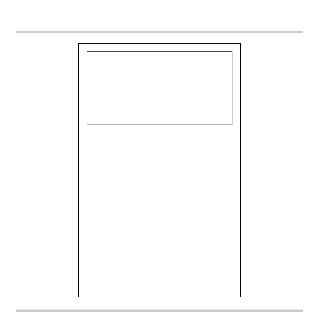
Features of the Appliance
Control Knob
Burner Parts
1 Pot grids
(3 parts, the left and right part are identical)
2 Large (Wok) burner 17,000 BTU (5 kW)
3 Large burner 14,000 BTU (4 kW)
4 Normal burner 6,500 BTU (2 kW)
5 Ventilation openings
6 Symbol for corresponding cooking position
7 Indicator light
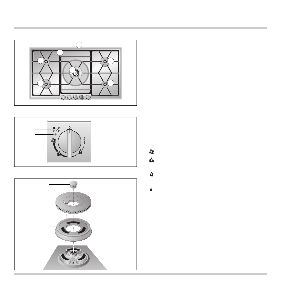
8 Flame setting:
0 OFF
High setting of outer and inner flame ring
Low setting of outer flame ring
High setting of inner flame ring
Outer flame ring off
High setting of inner flame ring
Outer flame ring off
Low setting of inner flame ring
9 Burner head cover
10 Burner ring
11 Burner head
12 Electrode for automatic ignition,
flame detection and flame control
4. Features
10
9
11
12
3
3
5
4
4
2
1
6
7
8
Page 10
9
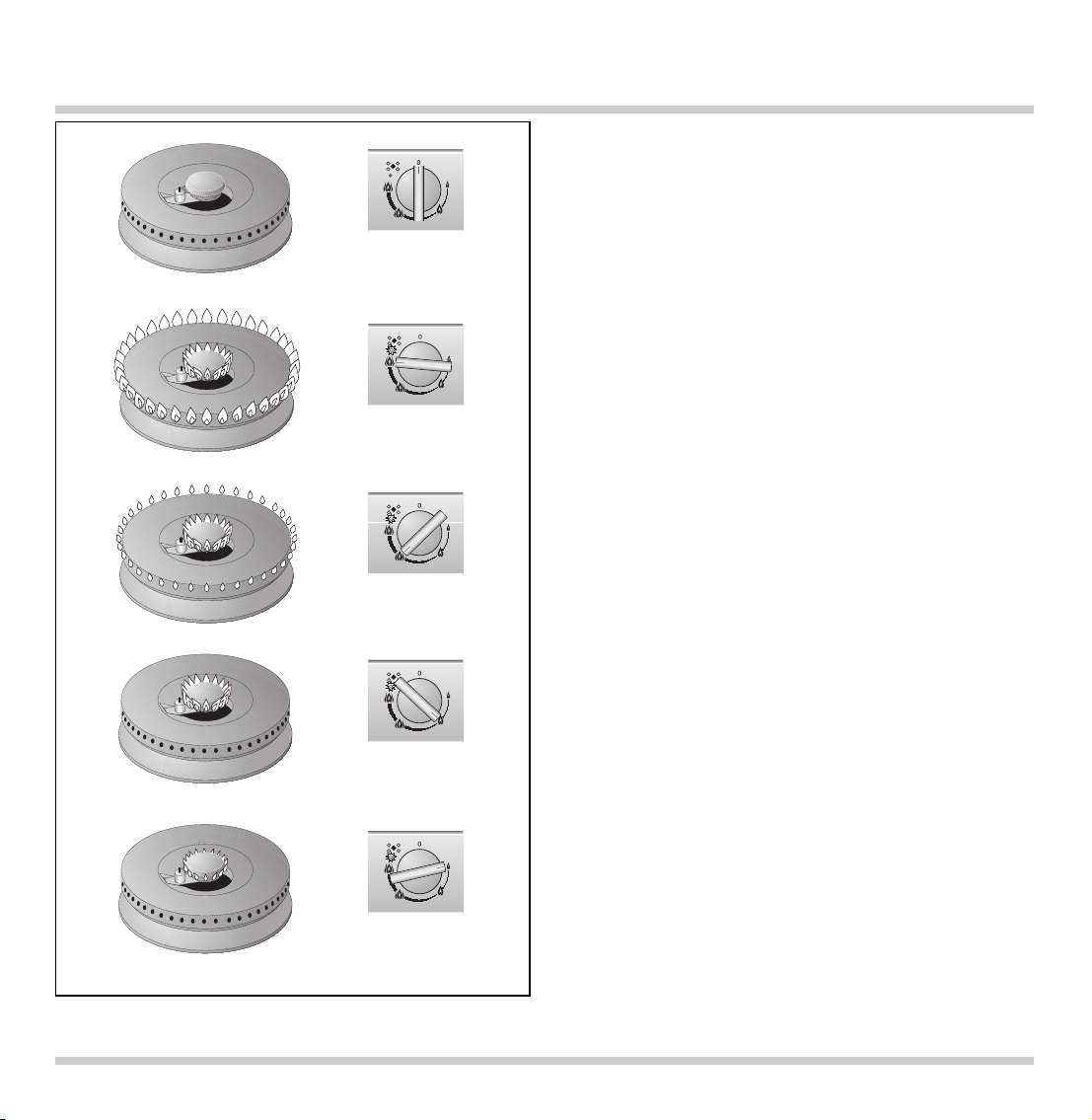
5. Operating Principle
The gas hob features two normal burners,
two large burners and a Wok burner.
The appliance features one-hand operation, flame
detection and automatic re-ignition. The ignition is
activated when the control knob is turned.
Should the flame go out during operation, the
appliance will automatically re-ignite the burner.
During a disturbance, the appliance will cut off the
gas supply as a safety measure, to prevent
unburned gas escaping.
The flame setting is infinitely variable between high
and low.
The total rated thermal load amounts to:
58,000 BTU (17 kW)
The specified rated load is defined by installation
of the fixed nozzles.
The gas hob is converted to a different gas
type by nozzle replacement (full and low-burning
nozzles) (see nozzle table on page 20-21).
Off
High
Low
Page 11

10
Switching on
• Place a suitable pot or a pan on the corresponding
cooking position.
• Press down the control knob for the corresponding
cooking position and turn it to the required
position between the and symbols. The burner
ignites automatically.
• When using large pots or pans you should ignite
the burner in the low position.
• Every time the gas hob is switched on, the
electronics run an auto test. All electrodes fire
and the required burner ignites after a few
seconds. When switching on further burners, only
the corresponding electrode fires.
• When being switched on, a short sound may be
heard when the electronic of the gas hob opens
the gas supply valve. This is a normal condition.
The flame size can be set continuously between full
and low by slowly turning the control knob.
Indicator light
The indicator light next to the control knob comes
on, if the burner is switched on and the flame burns
correctly.
Should the flame go out during operation (e.g.
because of a draught), the appliance will
automatically re-ignite the burner.
Should the re-ignition be unsuccessful (e.g. burner
is soiled by spilled over food or liquid), all burners
are switched off, the indicator lights of the burners
that were switched on flash. Turn all control knobs
to the OFF position. The flashing indicator lights will
go out except for the affected burner. This indicator
will continue to flash for a few seconds. After the
6. Operation
Only light a burner if all burner parts are dry, and
assembled correctly. Otherwise, malfunctions may
occur or the appliance may switch off.
Page 12

appliance has cooled down sufficiently, check this
burner to see if all the burner parts have been
assembled correctly. Check if the burner or the
electrode has been soiled (see trouble shooting
guide on page 19).
Note: if a malfunction occurs on one burner, you
can continue using the remaining burners, however,
you must turn all control knobs to the off-position
first, before recommencing.
Switching off
Fully turn the control knob to the OFF position.
The electronics of the appliance switch the gas
supply off, if all control knobs are in the off position.
11
Page 13

7. Burner Settings Chart
12
Cooking Cooking method Examples
level
High Boiling Water
Searing Meat
Heating Fat, liquids
Boiling Soup, sauce
Blanching Vegetables
Roasting Meat, fish, potatoes
From Browning Flour, onions
Roasting Almonds, breadcrumbs
Baking Pancakes, egg dishes
to Boiling in open pot Liquids
Simmering in open pot Dumplings, sausages, soup garnish,
meat stock, poached eggs
Simmering Sweet sauces
From Boiling with closed lid Pasta, soup, sauces
Steaming Vegetables, potatoes, fish
to Stewing Vegetables, fruit, fish
Braising Goulash, rolled beef steaks, roasts,
vegetables
Low Thawing Frozen foods
Slow cooking Rice, pulses
Reheating Soup, casserole, vegetables in a sauce
Switch to the high setting in order to reach the required temperature quickly. Then switch back to a lower
setting.
The output of the inner flame ring is the same on the normal, as well as the large burners.
The values given above must be looked upon as recommended values. The heat required depends not
only on the type and condition of the food, but also the size and contents of the pot.
Due to the high performance of the cooktop, fat and oil will heat up quickly. Never leave the cooktop
unattended, fat can ignite, food can burn.
Preferably use the rear cooking zones to prepare meals, that need longer to cook.
Preferably use the larger burners or the wok burner for brief cooking, deep fat frying and brief frying of
large quantities.
Page 14

Pots with a diameter of less than 90 mm (3 1/2´ ´ ) or
more than
280 mm (11 ´ ´ ) / 320 mm (12 1/2´ ´ ) for
the large (WOK) burner
should not be used.
When using large pots, pay attention to keeping to
a minimum distance of
50 mm (2 ´ ´ ) between the
cooking vessel and combustible surroundings.
A minimum distance of
50 mm (2 ´ ´ ) must be
observed between the control knob / control panel
and the pot or pan. The pot or pan should not touch
the control panel.
When buying pots, pay attention to the fact
that the manufacturer frequently specifies the top
pot diameter, which is generally larger than the
diameter of the base.
Observe the manufacturer’s specifications! Use
cooking utensils that the manufacturer states as
being “suitable for gas". Use pots with heat resistant
handles.
Use pots and pans with a thick base, because heat
distribution is particularly improved in the low
setting. Using the correct size of pots and pans for
the burner ensures improved cooking performance
and energy efficiency.
To ensure an even distribution of heat, center the
pot above the burner. The flames should be
covered by the pot base.
Place the pot or pan securely and level on the pot
grid. Turn the pan handle to the side, it should not
point to the front. In order to guarantee a secure
position on the pot grid, the pot base should be flat
and not warped or dented.
Placing a fitting lid on the pot will shorten cooking
times. Through a glass lid you can watch the
cooking progress without having to take the lid off.
8. Cookware Recommendations
13
KG 291 Recommended Minimum
pot diameter pot diameter
Normal Burner 7 3/4´ ´ - 9 1/2´ ´ 3 1/2´ ´
Large Burner 9
1
/2´ ´ - 11´ ´ 3 1/2´ ´
Large Burner (Wok) 9
1
/2´ ´ - 12 1/2´ ´ 6 1/4´ ´
Page 15

The Wok and Accessories
(not included in the scope of delivery)
– The round-bottom wok is the ideal wok for your
gas cooktop.
– The wok looks like a hollow semisphere with a
long handle or wooden handle. It has a rounded
base and slanted sides. The thin steel passes the
heat swiftly to the inside, but soon cools down
again as soon as the flame is set to a lower
setting. Therefore, ingredients cannot overcook.
– The diameter is between 35 - 40 cm / 14 - 15
3
/4”
for 4 persons.
– Make sure that a wok with a rounded base is
positioned safely on the pot grid.
– Woks may consist of various materials. Cast-iron
woks are more stable and keep the heat longer.
– They have a round, high cover. Therefore, they
are also capable of steaming and stewing.
– The semicircular grid is hooked in on the edge of
the wok. On it, you can steam ingredients, you
can allow deep fried foods to drip or you can
keep browned foods warm.
– Use the chan (rounded spatula) or the wooden
pan reversing implement.
– Use a ladle to remove foods.
– Use the strainer to lift deep fried foods from the
fat or large pieces out of a sauce.
– You can use bamboo baskets for steaming.
Cooking in the Wok
You can fry, steam, deep fry, stew and cook normally.
Stir frying is the special cooking method for the
wok. Ingredients cut into small pieces are cooked
as briefly as possible under strong heat and
constant stirring. In the large, round pan everything
can be stirred and turned faster and with greater
ease than in a conventional frying pan. Thanks to
stirring, ingredients do not burn onto the pan.
Surplus oil drains off towards the middle. In next to
no time, you obtain delicious roasted foods, the
pores in meat close and fish becomes nices and
juicy. Vegetables stay crispy, and aromas and
healthy vitamins are retained.
Important: the cooking time is so short that all
ingredients should be ready for cooking before you
begin. The correct sequence is also important. First
place the ingredients with the longest cooking time
in the wok. For example, these are hard-fibred
vegetables such as carrots. Soft vegetables such as
mushrooms or sprouts are added later.
Proceed as follows:
– Pour sufficient oil into the wok to coat the surface.
We advise you to use peanut or or soya oil.
– Heat up the oil to just before the smoking point;
only then begin with stir frying.
– Cut the food into pieces of equal size, but not too
small, thus making sure they will not burn.
– If you are cooking larger quantities, work with
portions as otherwise not all of the food will reach
the hot base of the wok.
– Meals that are ready ca be kept warm on a
minimal flame. Clean the wok after every use and
rub its inside with oil. This will prevent rusting.
9. Wok Cookware Recommendations
14
Page 16

15
Keep the ventilation openings on the rear of the
appliance clean. Do not block the ventilation
openings.
The burners (burner head cover, burner ring and
burner head) will change their color during
operation and become darker. This change in color
will not influence the use-value.
Please thoroughly clean the appliance before
operating it for the first time and after every use.
10. Cleaning and Care
burner assembly wok burner
burner head cover
burner ring
burner head
electrode
burner base
burner assembly normal burner / large burner
Note: to avoid jeopardising the electrical safety of
the appliance, do not use high-pressure or steam
jet cleaning devices – risk of short circuits!
Caution, risk of burns! Before cleaning,
please wait until the cooktop has cooled.
Never switch on the cooktop while cleaning.
Page 17

Do not use scouring agents, abrasives or chemically
aggressive cleaners (for example oven cleaner)!
Do not use any nitro polishing agents for cleaning!
Do not use any abrasive sponges either.
Before cleaning, please wait until the cooktop
has cooled.
• First lift one of the pot grids on the side with both
hands (be careful not to scratch the base). Then
remove the remaining two pot grids.
• Remove the
burner head cover, the burner ring
and the burner head.
•
Important! Only clean the burner parts when
cold!
• Soak
burnt-in remainders in a little water and
detergent. This loosens even the most stubborn of
soiling. Do not use any abrasive agents and
abrasive sponges.
• Only use very little water to clean your cooktop.
Be careful that no water enters the burner base.
• As the result of heat development, slight discoloration can appear on the stainless steel
surface.
Do not attempt to scrape away such
discoloration.
This damages the surface.
Distribute stainless steel care agents uniformly
and thinly on the hob (not on the control panel!).
This will ensure an even surface and will keep
your hob in a good condition for a long period of
time.
• Make sure the burner parts are dry before
assembly. Only operate the appliance with all
parts dry. Damp burner parts will cause
malfunctions when igniting or unstable flames.
• When assembling the burner parts, make sure
that the burner ring and burner head are placed in
such a way that the locking lugs fit in the
corresponding recesses.
•
Important! Fit the middle pot support first
(be careful to center it over the burner) and
then the pot supports on the side. The
rounded corners of the pot supports on the
side must face out to the side.
16
Part / Material Suggested Cleaning Procedure Important Reminders
Control Panel Use cloth with detergent and hot water. Do not use strongly alkaline cleaning
(anodized Remove greasy splashes with a agents. These cleaners may cause
aluminum) commercially available cleaner for permanent discoloration!
aluminum. Make sure the cleaning
agent will not scratch the surface.
Control Knobs Use cloth with detergent and hot water. Do not clean in a dishwasher.
(mat chromium
plated )
see next page
Page 18

17
Part / Material Suggested Cleaning Procedure Important Reminders
Pot Grid Take pot grids off for cleaning. Do not clean in a dishwasher.
(enamel on Soak in sink. Clean with detergent Soak burnt-in remainders in sink.
cast iron) and brush. Abrasive cleaners, used too vigorously or
too often can eventually mar the enamel.
Burner Head Cover, Remove coarse soiling with damp Do not clean in a dishwasher.
Burner Ring, cloth and detergent. Port openings must be kept free.
Burner Head Use brass polish to keep the Be careful not to loose the small parts.
(brass) original shiny surface.
Wok Burner Head Clean with detergent and brush. Do not clean in a dishwasher.
(enamel on
cast iron)
Electrode Clean with brush, fine glass-paper Soiled electrodes may cause malfunctions
or scouring pad. when igniting or flame control disturbance.
Be careful when cleaning electrodes,
they are fragile, do not turn.
Caution: never switch on cooktop while
cleaning electrodes.
Base Cloth with detergent and hot water. To prevent marring the polished stainless
(stainless steel, Soak burnt-in remainders with a steel trough, always polish in the direction
shot blasted, little detergent solution. of the polish lines.
brushed) After cleaning, polish dry with a Light discolorations may form if the
soft cloth to prevent water stains natural oxidation is removed together
forming on the surface. with the soiling. Put some commercially
For heavy soiling, you can order available stainless steel polish on a cloth
our stainless steel cleaner (Order and polish the whole cooktop after cleaning
No. 310631) from your Gaggenau to get an even stainless steel surface.
dealer. Never allow food stains or salt to remain
Caution: no liquid should enter on stainless steel for any length of time.
the housing of the cooktop
Important: certain stainless steel cleaners
through the burner base. will scratch the surface. Chlorine or
chlorine compounds in some cleaners are
corrosive to stainless steel. Check
ingredients on label.
Page 19

The appliance must be disconnected from the
power and gas supply during all repair work.
In the event of malfunctions, check whether the gas
and electricity supplies are in proper working
order.
The cooktop cannot be used during a power failure.
If the cooktop is being used when the power failure
occurs, turn all of the burner control knobs to the
OFF position. The cooktop will not turn back on
after a power failure until all control knobs are first
turned OFF and then turned back on again.
Before calling the service engineer, check the
trouble-shooting guide on page 19 to see, if you can
rectify the problem yourself. If your appliance still
does not work, please contact your Gaggenau
dealer who will provide you with the address and
telephone number of your nearest manufacturer’s
authorized service agent or contact Gaggenau USA
on (800) 828-9165. Specify the appliance type (see
rating plate).
Repairs may only be carried out by authorised
technicians, in order to guarantee the safety of the
appliance.
Unauthorised tampering with the appliance will
invalidate any warranty claims.
Only use original spare parts.
18
11. Maintenance
Page 20

12. Trouble Shooting
19
Switch the appliance on again. Should the appliance still not work, contact your Gaggenau after-sales service.
Burner does not ignite when switched on
Indicator lights
are off
All indicator
lights are flashing
Indicator lights go off, only
the indicator light of the
affected burner continues to
flash for a few seconds
Indicator light of
the switched on
burner is flashing
No electrical
power
• Check the
domestic fuse
•
Is the appliance
plugged in?
• Are all burner
parts correctly
assembled?
• Is the g
as shut-
off valve open?
• Is the burner
dry and clean?
• Is there an air
pocket in the
gas supply line
after first installation or
changing the LP
(propane) gas
tank?
• LP (propane)
gas: is the gas
tank empty?
Wait, until the appliance
has cooled.
Check affected burner:
• Are all burner parts
correctly assembled?
• Is the e
lectrode soiled
(food remains) or wet?
• Is the burner soiled by
boiled over food?
• Check for strong draughts
(for example open window
behind the cooktop)?
• LP (propane) gas: is the
gas tank empty?
Turn control
knob to 0
Burners go off during operation
Turn all control knobs to 0
Turn control
knob to 0
Indicator lights
go off
After a power cut, the
appliance does not re-ignite
automatically
Check the power supply
Overheating
protection
Wa it, until
indicator lights
go off
Page 21

20
Technical data (gas)
Burners: Normal burner
Full burning 7,000 BTU (2 kW)
Low burning 700 BTU (0.175 kW)
Large burner
Full burning 13,500 BTU (4 kW)
Low burning 700 BTU (0.175 kW)
Wok burner
Full burning 17,000 BTU (5 kW)
Low burning 1,000 BTU (0.3 kW)
Total output 58,000 BTU (17 kW)
Gas connection: R 1/2’’ union nut for R 1/2’’
bracket to DIN 1999, conical-cylindrical
Technical data (electrical)
Rated consumption
15 W
Voltage AC 120 V
Frequency 60 Hz
Technical modifications reserved.
13. Technical Data / Settings Table
Nozzle, full burn, outer 1.55 110 A
Nozzle, low burn, outer 0.75 0.56
Nozzle, full burn, inner 0.60 0.42
Nozzle, low burn, inner 0.48 0.34
Air gap adjustm. outer [mm] 0 0
Air gap adjustm. inner [mm] open, fixed 6 (open)
Nozzle table wok burner
Nozzle tables
Countries US CA US CA
Gas family Natural gas LPG/Prop.
Pressure 6” W.C. (1.5 kPa) 10” W.C. (2.5 kPa)
Total output (5 burners) 58,000 BTU (17 kW) 58,000 BTU (17 kW)
Page 22

21
Nozzle, full burn, outer 1.50 1.05
Nozzle, low burn, outer 0.65 0.45
Nozzle, full burn, inner 0.40 0.29
Nozzle, low burn, inner 0.42 0.28
Air gap adjustm. outer [mm] 0 2
Air gap adjustm. inner [mm] open, fixed open, fixed
Countries US CA US CA
Gas family Natural gas LPG/Prop.
Pressure 6” W.C. (1.5 kPa) 10” W.C. (2.5 kPa)
Total output (5 burners) 58,000 BTU (17 kW) 58,000 BTU (17 kW)
Nozzle table large burner
Nozzle, full burn, outer 0.97 0.68
Nozzle, low burn, outer 0.48 0.34
Nozzle, full burn, inner 0.40 0.29
Nozzle, low burn, inner 0.42 0.28
Air gap adjustm. outer [mm] 0 open at maximum
Air gap adjustm. inner [mm] open, fixed open, fixed
Nozzle table small burner
Page 23

Important Notes
Please observe the general safety notes and the
important information in chapter 1 and 2.
The appliance must be installed and connected by
an authorised specialist before operation. Before
operating the appliance for the first time, make
sure that the power and gas supply connection are
in proper working order.
The installing technician is responsible for perfect
functioning of the appliance at its installation
location.
He must show the user how to switch off the
electricity and gas supply whenever required.
Caution:
before connecting the appliance, please check
whether the local connection conditions such
as gas type, gas pressure and mains voltage
match the appliance settings.
This gas hob
conforms to the categories that are specified on the
rating plate. The rating plate can be found on the
appliance and additionally on the quality control
slip which is included with these instructions. By
replacing nozzles, it is possible to set the appliance
to any gas listed on the rating plate.
If the data should not match, the appliance must
be changed over to the required gas type and the
available pressure.
As this gas hob is not intended for connection to an
exhaust gas system, pay attention to the applicable
installation conditions.
The appliance may be installed in kitchen
combinations made of wood or similar combustible
materials without taking additional measures. The
rear wall must consist of non-combustible material.
The minimum distances as described on page 23
must be observed.
The hob conforms to appliance class 3 and must be
installed in the countertop as shown in the
installation sketch.
We strongly recommend installation of a hood of at
least 36 ´ ´ / 900 mm width above the cooktop. The
minimum distance from the cooktop to the bottom
edge of the wall hood is 30 ´ ´ / 762 mm.
When using more than 2 rings at the same
time, please operate the extractor hood at
level 2 or higher. This prevents a build-up of
heat in the extractor hood.
Wall trims must be heat-resistant, and the minimum
distance between the hob and the wall trim is at
least 1
9
/16´ ´ (40 mm).
Remove the packaging from the appliance and
dispose of it according to local regulations. Be
careful to remove all accessories from the
packaging. Keep packaging elements and plastic
bags away from children.
Check the appliance for transport damage before
installing it.
Technical modifications reserved.
22
14. Installation Instructions
Page 24

Cabinet Requirements
The minimum spaces that must be maintained when
installing the gas cooktop shall be:
A minimum 12 ´ ´ (300 mm)
B minimum 12 ´ ´ (300 mm)
C minimum 30 ´ ´ (762 mm) clearance between the
top of the cooking surface and the bottom of
exhaust hood
D minimum 19/16´ ´ (40 mm)
E minimum 36 ´ ´ (914 mm)
F minimum 18 ´ ´ (458 mm)
23
Page 25

Electrical Connection
Electrical connection (AC 110-127 V) is established
by means of a connecting cable with a grounding
contact plug connected to a grounded socket,
which must also be accessible after installation of
the gas hob.
If, after installation of the gas hob, not all poles can
be isolated from the power by removing the plug,
an isolating device with a contact gap of at least
3 mm must be permanently installed. When establishing connections, make sure that the connecting
lead cannot come into contact with hot parts of the
gas hob or other hot parts.
Warning:
this appliance is equipped with a three prong
grounding plug for your protection against shock
hazard and should be plugged directly into a properly grounded receptacle. Do not cut or remove
the grounding prong from this plug.
The mains connecting cable must at least
correspond to type SJT 3x18 AWG/UL/CSA or it
must be correspondingly heat-resistant (at least
105 °C).
The mains connecting cable must only be
purchased through and connected by an
authorised specialist.
24
G
floor
8-12” (200-300 mm)
24” (610 mm)
max 8”
(210 mm)
G : gas connection
: electric socket
Page 26

Gas Connection
Before connecting the appliance, please check
whether the local connection conditions such as
gas type and gas pressure match the appliance
settings.
Make sure the gas supply is turned off at the
manual shut-off valve before connecting the
appliance.
The gas connection must be in a location that
permits access to the manual shut-off valve and
which, if applicable, is visible after opening the
door of the cabinet.
SERVICER INFO ONLY
Connect the gas supply using the 1/2´ ´ U.S.A. elbow
and the fiber gasket supplied with the unit. The
shorter, nontapered thread fits into the threaded nut
on the hob. The longer, tapered U.S.A. thread is for
the incoming gas supply. Vent the gas line, check
for leaks. The gas pressure regulator is supplied
with the unit and comes set for natural gas. To
convert regulator to LP (propane) gas:
Make-Essex Model SX 229 NA-602
1
/2 PSIG
1. Remove the aluminum cap from the top of the
regulator.
2. Turn the cap over. It will have LP 10 stamped
inside.
3. Replace the cap on the regulator.
Make-Maxitrol Model RV 47 CL
1
/2 PSIG
1. Remove the aluminum cap from the top of the
regulator.
2. Remove the yellow plastic shaft from the cap by
pushing it sideways until it pops out of the
groove in the cap.
3. Turn the shaft over and push back into the cutout in the cap.
4. Replace the cap on the regulator.
25
Page 27

Nozzle Replacement
Changing over to a different gas type
Only authorised servicers are permitted to
change over to a different gas type.
The nozzles needed for the gas type to be set
are available as a conversion kit. Please specify the
appliance type and the required gas type. The
nozzles can be changed on the installed appliance.
Loads for all gases
For all gas types and pressures, the rated load
is achieved by installing the high and low setting
nozzles for the required gas type (see nozzle
table).
Replacing the low setting nozzles
• Switch off the power at fuse point and close the
gas supply!
• Detach pod grids, burner rings, burner head
covers and burner heads.
• Pull off control knobs. Undo trough securing nuts
(three 7 mm nuts on each burner) and carefully
detach the trough.
• Turn the black plastic part so that the recess is
above the nozzle. Screw out nozzle and take
nozzle out with small pliers.
• Replace both low setting nozzles on the gas taps
according to the new gas type and as detailed in
the low setting nozzle table. Fully screw in the
new low setting nozzles.
Important: be careful not to damage the O-ring.
26
See table on page 20-21
for details of nozzle settings.
outer low
setting nozzle
inner low
setting
nozzle
Page 28

27
Replacing the main burner nozzles of the
normal burner and large burner
• Detach the safety spring on the supply lines.
Leave the electrode connected. Unscrew the
burners from the trough (Torx T20) and pull off the
burner from both supply lines.
• Carefully pull off both main nozzles together with
the O-ring by hand.
• Check whether the O-rings of the new nozzle
seats are fitted correctly. Fully push nozzles onto
the supply lines.
Note: do not bend supply lines.
• Push the burners onto the supply lines.
Push the safety springs back on.
• Screw the burners back on the trough.
• Loosen the locking screw and adjust the air
regulation bush according to the nozzle table.
Tighten the locking screw.
See table on page 20-21
for details of nozzle settings.
outer main nozzle
inner main nozzle
Page 29

Replacing the main burner nozzles of the
wok-burner
• Unscrew the Wok burner from the trough
(Torx T20). Loosen locking screw from the air
regulation bush. Fully push in the air regulation
bush. Detach the safety springs on the supply line.
Leave the electrode connected.
• Carefully pull off the Wok burner from both supply
lines. Carefully pull off the inner main nozzle with
O-ring by hand. Screw out the outer main nozzle
(10 mm).
• Check whether the O-ring is fitted correctly in the
nozzle seat of the new inner main nozzle. Fully
push nozzle onto the supply lines.
Note: do not
bend supply lines.
• Change the screw-in nozzle and tighten it firmly.
• Push the burners onto the supply lines.
Push the safety springs back on.
• Screw the burner back on the trough.
• Loosen the locking screw and adjust the air
regulation bush according to the nozzle table.
Tighten the locking screw.
• Fit the trough and tighten it firmly.
Checking functions
The flames are adjusted correctly if no yellow tips
are visible and if they do not go out when switching
over swiftly from the high to the low setting.
Please do not forget to stick the new adhesive label
included with the nozzle set over the old adhesive
label on the gas connection, thus documenting the
changeover to a different gas type.
28
See table on page 20-21
for details of nozzle settings.
outer main nozzle
inner main
nozzle
Page 30

Installing the Appliance
The appliance is installed in a base cabinet with a
width of more than 36 ´ ´ (914 mm).
Do not install the appliance above a drawer.
• Produce the recess for the cooktop in your
countertop. Proceed as indicated on the
installation sketch.
Note: the angle between the cut surface and the
worktop must be 90°.
• Turn the clamping screws to the side. Insert the
hob with the control panel on the front into the cutout.
• Align the cooktop and turn the clamping screws
under the countertop. Tighten the clamping
screws evenly.
• Connect the appliance to the gas supply.
Note: if a flexible gas connection is being used,
you can connect the appliance before installing it
into the worktop.
• Check the installation for gas leaks.
• Connect the appliance to the electricity. Test it for
correct functioning.
• There might be an air pocket in the gas supply line
if the appliance switches off and the indicator
lights flash. Turn all control knobs off and switch
on again (see trouble-shooting guide).
5080008627ind01 en 12.04 EB 29
"
36
"
*
11
/
32
"
at ventilation openings
21
/
32
*
"
1
/
8
5
"
1
/
8
55
min. 1
min. 2
"
3
/
8
"
5
/
16
19
"
"
15
/
16
6
"
7
/
16
17
34
20
min.
1
"
1
/
16
"
3
/
16
"
7
8
/
Page 31

5551 McFADDEN AVENUE
HUNTINGTON BEACH, CA 92649
USA
Y (800) 828-9165 · FAX (714) 901-0979
www.gaggenau-usa.com
GAGGENAU HAUSGERÄTE GMBH
CARL-WERY-STR. 34 · 81739 MÜNCHEN
GERMANY
Y (0 89) 4590-03
FAX (089) 45 90-23 47
 Loading...