

Page 1
USER AND MAINTENACE MANUAL
This manual must be kept for future reference and must always remain with the machine
FLEXIMA
EN
Horizontal beam panel saw
SCM GROUP spa - GABBIANI
S.P. 258 Marecchia n. 30-34-57
47827 Villa Verucchio (RN) – ITALY
Tel. 0541/674711 – Fax. 0541/674705
THIS MANUAL IS PROPERTY OF - SCM GROUP SPA. - ANY TOTAL OR PARTIAL REPRODUCTION IS STRICTLY FORBIDDEN
Page 2
MANUFACTURER: SCM GROUP S.p.a. GABBIANI
ADDRESS: S.S. 258 Marecchia, 30-34-57
47827 Villa Verucchio (RN) - ITALY
TYPE OF DOCUMENT: USER AND MAINTENACE MANUAL
DOCUMENT CODE: 0000571191F
EDITION:
PRODUCT: FLEXIMA
MODEL: 105-125
SERIAL NO.:
CUSTOMER:
CUSTOMER SERIAL NO.:
YEAR OF MANUFACTURE:
CONFORMITY:
THIS MANUAL IS PROPERTY OF - SCM GROUP SPA. - ANY TOTAL OR PARTIAL REPRODUCTION IS STRICTLY FORBIDDEN
Page 3

INDEX
1 GENERAL INFORMATION............................................................................................................... 1
1.1 MACHINE IDENTIFICATION..................................................................................................... 2
1.2 CORRESPONDENCE DATA..................................................................................................... 3
1.3.1 LIST OF DOCUMENTATION PROVIDED .............................................................................. 3
1.3.2 PURPOSE OF THE MANUAL ................................................................................................ 3
1.3.3 HOW TO CONSULT THE MANUAL....................................................................................... 3
1.4.1 USE OF SYMBOLS AND ICONS IN THIS MANUAL............................................................. 4
1.4.2 SAFETY SIGNS AND PLATES - DESCRIPTION .................................................................. 5
1.4.3 SAFETY SIGNS AND PLATES - POSITION.......................................................................... 7
1.5 MACHINE DESCRIPTION (fig. 1.1) .......................................................................................... 8
1.6 MACHINABLE AND NONMACHINABLE MATERIALS - DIMENSIONS OF MATERIAL THAT
CAN BE SAWED .............................................................................................................................. 9
1.7 ENVIRONMENT......................................................................................................................... 9
1.9 PROHIBITED USES .................................................................................................................. 9
2 MACHINE SAFETY .......................................................................................................................... 1
2.1 GENERAL SAFETY INFORMATION ........................................................................................ 2
2.2 SAFETY DEVICES .................................................................................................................... 4
2.3 EMERGENCY DEVICES ......................................................................................................... 15
2.4 RESIDUAL RISKS ................................................................................................................... 18
3 TECHNICAL SPECIFICATIONS....................................................................................................... 1
3.1 TECHNICAL SPECIFICATIONS (STANDARD MACHINE) ...................................................... 2
3.2 OPTIONALS .............................................................................................................................. 3
3.3 OPTIONAL UNITS-DESCRIPTION ........................................................................................... 4
3.4 NOISE EMISSION...................................................................................................................... 9
4 TRANSPORT AND INSTALLATION ................................................................................................ 1
4.1 MACHINE INSTALLATION ....................................................................................................... 2
4.2 TRANSPORT, PACKAGING AND UNPACKING.................................................................... 46
4.3 MOVING THE MACHINE......................................................................................................... 52
4.4 FIXING TO THE FLOOR (Fig. 4.4).......................................................................................... 64
4.5 ELEMENT ASSEMBLY, REMOVAL OF LOCKS AND LEVELLING...................................... 65
4.6 CONNECTING UP THE POWER SUPPLY (Fig. 4.6) ............................................................. 74
4.7 CONNECTING UP THE AIR SUPPLY (Fig. 4.7-4.7a)............................................................. 77
4.8 SUCTION CONNECTION (Fig. 4.8) ........................................................................................ 78
THIS MANUAL IS PROPERTY OF - SCM GROUP SPA. - ANY TOTAL OR PARTIAL REPRODUCTION IS STRICTLY FORBIDDEN
Page 4

INDEX
5 DESCRIPTION OF COMMANDS AND CONTROL FUNCTIONS.................................................... 1
5.1 MACHINE PREPARATION........................................................................................................ 2
5.2 DESCRIPTION OF COMMANDS AND CONTROL FUNCTIONS............................................. 3
6 MACHINE SET-UP AND USE .......................................................................................................... 1
6.1 STARTING UP THE MACHINE ................................................................................................. 2
6.2 STOPPING THE MACHINE....................................................................................................... 2
6.3 CRITERIA FOR CORRECT USE OF THE BLADES AND THEIR DIMENSIONS..................... 3
6.4.0 ASSEMBLY AND DISASSEMBLY OF THE BLADE AND SCORING SAW ......................... 9
6.4.1 ASSEMBLING AND DISASSEMBLING PRECUTTING UNIT BLADE AND PRE-SCORER15
6.5 SCORING BLADE OPERATION ............................................................................................. 17
6.6 SCORING SAW ADJUSTMENT (Fig. 6.6) .............................................................................. 18
6.7 POSTFORMING ENGRAVING EXECUTION only for the wood cut and by-products of the
wood ............................................................................................................................................... 20
6.8 ADJUSTMENT OF ENGRAVING DEPTH IN PANEL (“GROOVE”) (Fig. 6.8)....................... 21
6.9 ADJUSTMENT OF PERPENDICULARITY BETWEEN THE WOOD GUIDE AND THE
CUTTING LINE (Fig. 6.9) ............................................................................................................... 23
6.10 CLAMP HEIGHT ADJUSTMENT (Fig. 6.10)......................................................................... 25
6.11 ADJUSTING AND USING THE ALIGNER UNIT (Fig. 6.11) ................................................. 26
6.12 PNEUMATIC ADJUSTMENTS (Fig. 6.12) ............................................................................ 27
6.15 DRIVE BELTS ADJUSTING, X AXIS (Fig. 6.15/16) ............................................................. 29
6.16 DRIVE BELTS ADJUSTING, Z AXIS (Fig. 6.15/16).............................................................. 29
6.17 ADJUSTING DRIVE BELT TENSION ................................................................................... 29
6.18 ADJUSTING THE PHOTOCELL ........................................................................................... 30
6.19 ELEVATOR TABLE............................................................................................................... 30
6.20 THIN PANEL LOADING DEVICES........................................................................................ 31
20 MAINTENANCE................................................................................................................................ 1
20.1 MAINTENANCE AND CLEANING .......................................................................................... 2
20.2 ADJUSTING THE AIR TREATMENT UNIT (Fig.20.2) ............................................................ 4
20.3 BLADE CARRIAGE: GUIDE LUBRICATION, REPLACEMENTS AND ADJUSTMENTS ..... 5
20.4 PUSHER UNIT: REPLACEMENTS AND ADJUSTMENTS .................................................. 11
20.5 ADJUSTING AND MAINTAINING THE LIFT TABLE CHAIN............................................... 14
20.6 AUTOMATIC UNLOADING UNIT MAINTENANCE .............................................................. 15
20.7 TRIM CUT CONVEYOR AND CUTTING DEVICES MAINTENANCE................................... 21
20.9 LUBRICANT COMPARISON TABLE.................................................................................... 30
20.10 MACHINE SCRAPPING ...................................................................................................... 31
THIS MANUAL IS PROPERTY OF - SCM GROUP SPA. - ANY TOTAL OR PARTIAL REPRODUCTION IS STRICTLY FORBIDDEN
Page 5

105-125
EN
1 - GENERAL INFORMATION
INDEX
1.1 MACHINE IDENTIFICATION ..................................................................... 2
1.2 CORRESPONDENCE DATA.....................................................................3
1.3.1 LIST OF DOCUMENTATION PROVIDED .................................................3
1.3.2 PURPOSE OF THE MANUAL....................................................................3
1.3.3 HOW TO CONSULT THE MANUAL .......................................................... 3
1.4.1 USE OF SYMBOLS AND ICONS IN THIS MANUAL.................................4
1.4.2 SAFETY SIGNS AND PLATES - DESCRIPTION ......................................5
1.4.3 SAFETY SIGNS AND PLATES - POSITION .............................................7
1.5 MACHINE DESCRIPTION (fig. 1.1) ...........................................................8
1.6 MACHINABLE AND NONMACHINABLE MATERIALS - DIMENSIONS OF
MATERIAL THAT CAN BE SAWED ..........................................................9
1.7 ENVIRONMENT......................................................................................... 9
1.9 PROHIBITED USES...................................................................................9
THIS MANUAL IS PROPERTY OF - SCM GROUP SPA. - ANY TOTAL OR PARTIAL REPRODUCTION IS STRICTLY FORBIDDEN Cap. 1 - Pag. 1/9
Page 6
105-125
1 - GENERAL INFORMATION
EN
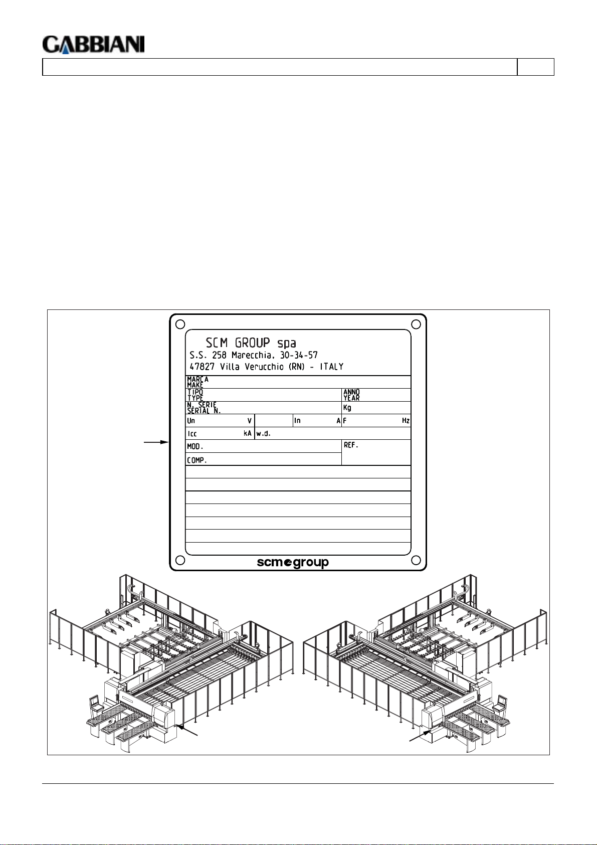
1.1 MACHINE IDENTIFICATION
(11.0)
The plate illustrated in Fig. 1.0 shows the identification data of the machine to be communicated each time our
service or spare parts centre is contacted.
MARCA - Manufacturer's name or make
TIPO - Machine type
ANNO - Production year
N°SERIE - Serial number
KG - Weight (Kg)
Un - Rated voltage (volt)
~ - Phases number (alternate current)
In - Rated current (ampere)
F - Frequency (herz)
Icc - Short circuit breaking capacity of the protective device (KA)
w.d. - Wiring diagram number
Mod. - Machine model
Comp. - Machine version
Ref. - Internal references
A
A
A
Fig. 1.1
Chap. 1 - Page 2/9 THIS MANUAL IS PROPERTY OF - SCM GROUP S.P.A. - ANY TOTAL OR PARTIAL RE P RODUCTION IS STRICTLY
FORBIDDEN
Page 7

105-125
EN
1 - GENERAL INFORMATION
1.2 CORRESPONDENCE DATA
(12.0)
When writing or calling the dealer or the manufacturer for any reason regarding the machine, always supply the
following information:
- Machine model
- Serial number
- Power supply voltage and frequency
- Date of purchase
- Name of dealer where machine was purchased
For information specifically regarding the electrical system, also supply the data listed on the plate.
1.3.1 LIST OF DOCUMENTATION PROVIDED
(13.1.0)
The following documentation is provided with the machine for use by expert operators.
Programming manual: contains the information needed to program the machine.
Wiring diagram: required by the expert operator to work on the electrical system.
Pneumatic diagram: required by the expert operator to work on the pneumatic system.
Spare parts catalogue: to order original spare parts.
Foundation and installation diagrams: required by the expert operator when installing the machine on the ground.
Use and maintenance manual: contains machine safety, use and maintenance information.
1.3.2 PURPOSE OF THE MANUAL
(13.2.0)
The Manufacturer issues this manual with the purpose of providing all the information and instructions necessary
for full and efficient use of the horizontal panel saw.
The drawings are furnished by way of example.
Even if the machine in your possession differs from the illustrations contained in this document, the
safety of and information on the machine are nonetheless guaranteed.
The consignee is the operator assigned to use the machine, who must have in-depth knowledge of the operating
modes, the adjustment and the ordinary maintenance operations necessary.
The user is completely responsible for the use of this manual; any operations not described in this
manual must be considered prohibited. An operator carrying out such operations shoulders all
responsibility for the results of his actions.
It is important to keep this manual for future reference.
1.3.3 HOW TO CONSULT THE MANUAL
(13.3.0)
This manual is arranged in sections, further divided into subsections to make each topic independent and at the
same time subordinate to an operating logic: (know – prepare – use).
THIS MANUAL IS PROPERTY OF - SCM GROUP SPA. - ANY TOTAL OR PARTIAL REPRODUCTION IS STRICTLY FORBIDDEN Cap. 1 - Pag. 3/9
Page 8

105-125
1 - GENERAL INFORMATION
EN
1.4.1 USE OF SYMBOLS AND ICONS IN THIS MANUAL
(14.1.0)
In order to prevent incorrect manoeuvres or accidents, it is first of all important to read this manual, paying
particular attention to all the text highlighted in bold type or underlined, and to the following messages:
HAZARD: Indicates imminent danger which may cause serious injury. Be careful.
CAUTION - PRECAUTION: Indicates that appropriate action must be taken in order to prevent
accidents or damage to things.
NOTE: Technical indications of particular importance.
Cap. 1 - Pag. 4/9 THIS MANUAL IS PROPERTY OF - SCM GROUP SPA. - ANY TOTAL OR PARTIAL REPRODUCTION IS STRICTLY FORBIDDEN
Page 9
105-125
EN
1 - GENERAL INFORMATION
1.4.2 SAFETY SIGNS AND PLATES - DESCRIPTION
(14.2.0)
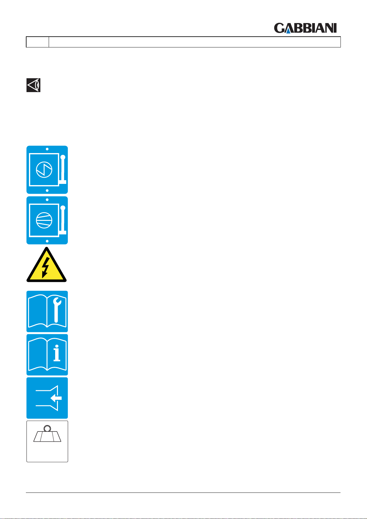
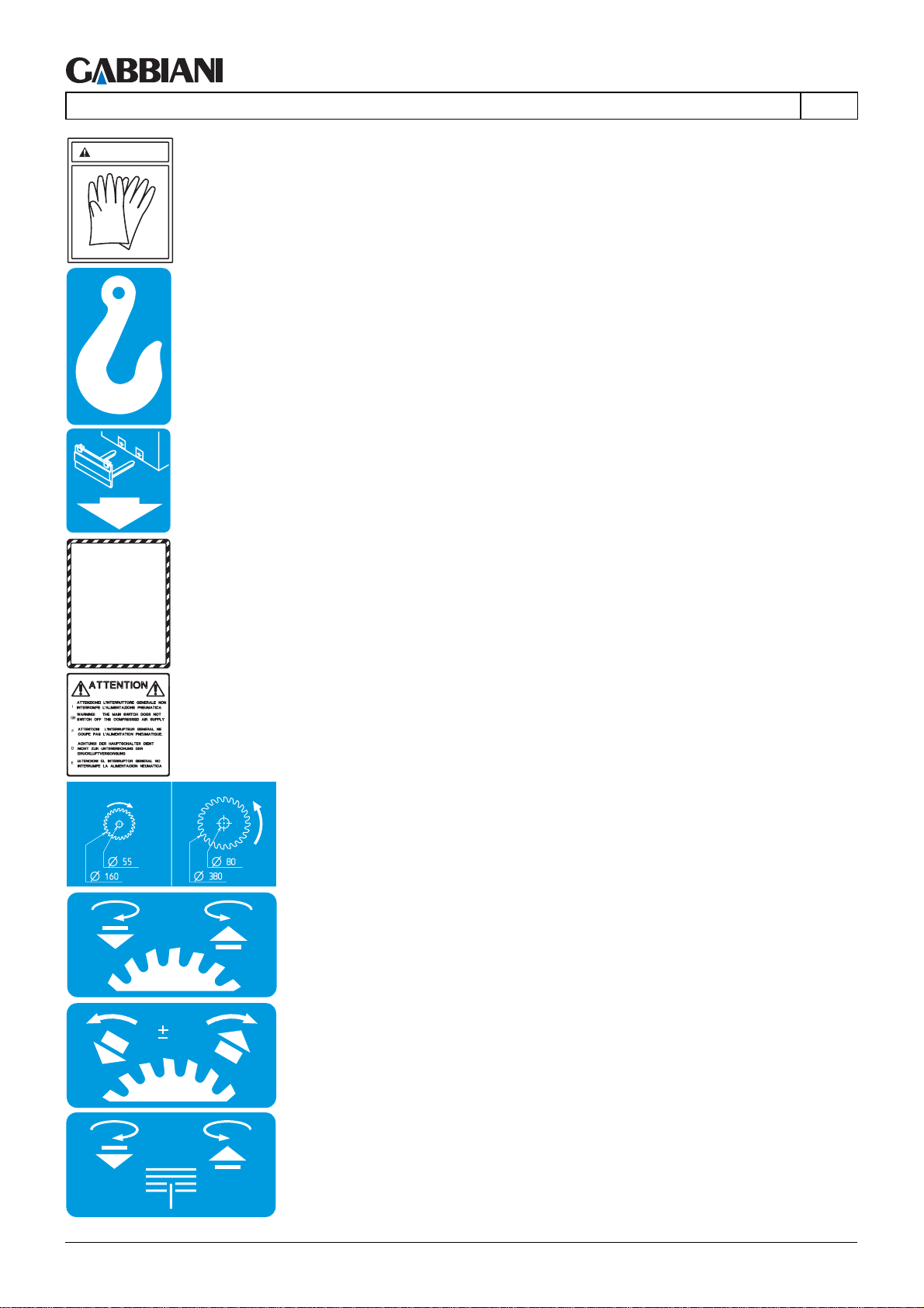
CAUTION: The operator must pay attention to the signs and plates fixed on the machine.
These may be:
– Blue rectangular, square or round information plates;
– Yellow triangular danger plates;
– White round prohibition plates.
Main switch: when at zero (OFF), it cuts electrical power supply to the machine.
Main air valve: when closed, it disconnects the compressed air supply to the machine.
Danger: high voltage. Turn the main electrical switch to zero and padlock it before opening any
guard with this symbol..
Consult manual for operations.
Consult manual for operations.
Suction point.
g.
k
(see paragraph 1.1).
THIS MANUAL IS PROPERTY OF - SCM GROUP SPA. - ANY TOTAL OR PARTIAL REPRODUCTION IS STRICTLY FORBIDDEN Cap. 1 - Pag. 5/9
Weight of the machine part; the total machine weight is shown on the “machine identification plate”
Page 10
105-125
1 - GENERAL INFORMATION
CAU
TION
Wear gloves.
Machine hooking point for lifting.
Lifting point with forklift.
AVVERTENZE
SAFETY PRECAUTIONS
MISES EN GARDE DE SECURITE
SICHERHEITSHINWEISE
ADVERTENCIAS DE SEGURIDAS
EN
General warning signs (example).
The main electric switch does not interrupt the air supply.
Indication of blade rotation direction and their dimensions (example).
Engraver vertical adjustment.
1
Engraver horizontal adjustment.
“Groove” depth adjustment.
Cap. 1 - Pag. 6/9 THIS MANUAL IS PROPERTY OF - SCM GROUP SPA. - ANY TOTAL OR PARTIAL REPRODUCTION IS STRICTLY FORBIDDEN
Page 11
105-125
EN
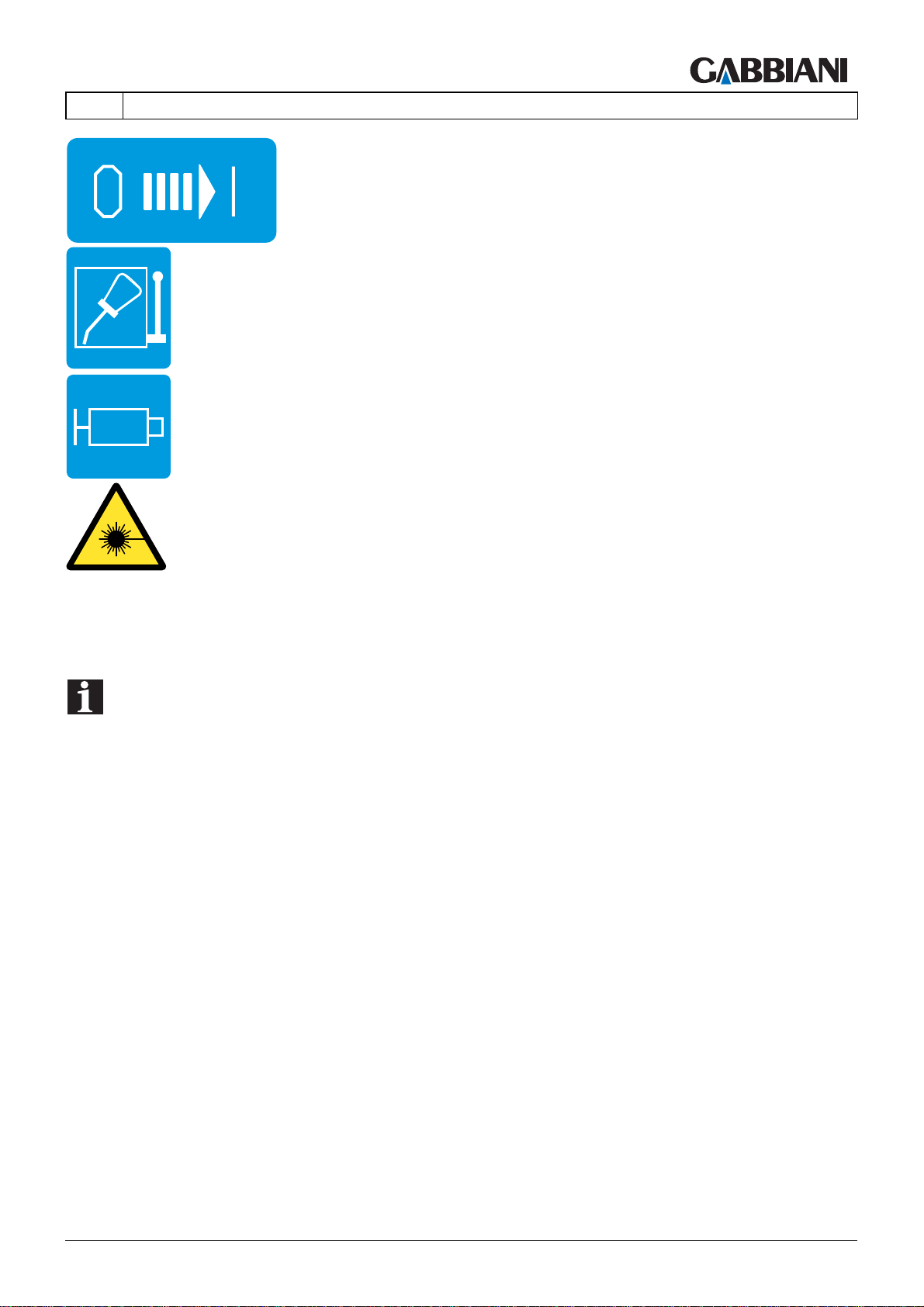
Position counter entered regulation blades
Lubrication control.
Grease point through grease nipple.
1 - GENERAL INFORMATION
Danger! Laser beam
1.4.3 SAFETY SIGNS AND PLATES - POSITION
(14.3.0)
NOTE: The signs and plates must be inspected and cleaned regularly to keep them clear and
legible.
If the signs and plates are not clearly legible, contact the manufacturer for their replacement.
In case of replacement, operate as follows:
- Remove the old sign or plate.
- Clean the area with detergent.
- Fit the new sign or plate, respecting the position and orientation of the old one.
THIS MANUAL IS PROPERTY OF - SCM GROUP SPA. - ANY TOTAL OR PARTIAL REPRODUCTION IS STRICTLY FORBIDDEN Cap. 1 - Pag. 7/9
Page 12

105-125
1 - GENERAL INFORMATION
EN
1.5 MACHINE DESCRIPTION (fig. 1.1)
(15.0)
The machine is a numeric control horizontal panel saw with two cutting lines (longitudinal and trasversal). It can
perform automatic sequence cutting of panels or packs of panels.
The machine must be used by a single person who, after having carefully read this manual, is trained
and authorised to carry out the work, apart from the panel loading and unloading operations that must be carried
out with suitable machinery and by personnel specialised and trained in this type of manoeuvre.
Cap. 1 - Pag. 8/9 THIS MANUAL IS PROPERTY OF - SCM GROUP SPA. - ANY TOTAL OR PARTIAL REPRODUCTION IS STRICTLY FORBIDDEN
Page 13

105-125
EN
1 - GENERAL INFORMATION
1.6 MACHINABLE AND NONMACHINABLE MATERIALS -
DIMENSIONS OF MATERIAL THAT CAN BE SAWED
(16.0)
The machine has been designed to cut to size solid wood panels, chipboards, MDF panels, multilayer
panels, plywood panels and fiber panels that may also have a plastic veneer. Such machine can perform the
aluminum cut and her leagues, plastics and her by-products, provided that predisposed for such workmanships.
The machine must not be used for materials other than those mentioned above.
This machine can only saw at the same time panels made of the materials mentioned above of the same thickness
or packs of panels made of the materials mentioned above of the same height.
1.7 ENVIRONMENT
(17.0)
The machine can operate under these conditions:
Temperature: min. + 1 °C - max. + 40 °C.
Max. altitude above sea level: 1000 m (in case of higher altitude consult the manufacturer)
Always connect the machine to the suction system which must be sufficiently dimensioned.
The machine may not be used in the open air.
The machine is designed for industrial use.
The machine may not operate in explosive environments.
1.9 PROHIBITED USES
(19.0)
It is forbidden:
- to use the machine in any way other than those described previously.
- to use the machine without the required safety guards or if any part of them has been removed.
- to use materials and dimensions other than those listed in the preceding paragraphs.
- to use tools not included in the EN847-1 regulation or tool sizes that are incompatible with machine specifications.
- If the machine is fitted with a laser device to view cuts: do not replace the laser with a different type of laser; in
case of failure it must only be repaired by the laser manufacturer; do not look inside the laser beam; do not use
optical devices (e.g. lenses, etc.).
- to tamper with the machine.
- If the machine is tampered with, its Declaration of Conformity becomes null and void, and the owner is obliged to
request a new Declaration of Conformity before restarting the machine.
- for children, pets or any unauthorised person to gain access to the machine.
Any damages deriving from improper use shall be the sole responsibility of the user.
THIS MANUAL IS PROPERTY OF - SCM GROUP SPA. - ANY TOTAL OR PARTIAL REPRODUCTION IS STRICTLY FORBIDDEN Cap. 1 - Pag. 9/9
Page 14

Page 15

105-125
EN
2 - MACHINE SAFETY
INDEX
2.1 GENERAL SAFETY INFORMATION .........................................................2
2.2 SAFETY DEVICES.....................................................................................4
2.3 EMERGENCY DEVICES .........................................................................15
2.4 RESIDUAL RISKS....................................................................................18
THIS MANUAL IS PROPERTY OF - SCM GROUP SPA. - ANY TOTAL OR PARTIAL REPRODUCTION IS STRICTLY FORBIDDEN Cap. 2 - Pag. 1/18
Page 16

105-125
2 - MACHINE SAFETY
EN
2.1 GENERAL SAFETY INFORMATION
(21.0)
This machine has been constructed to offer safe operating conditions without compromising performance.
However, maximum safety is in your hands. Certain risks are run in the use of any machine tool – keep this in
mind.
To prevent these risks and to work in the best conditions, carefully read this user manual right through before
starting the machine.
Some general safety rules:
- Wear suitable clothing (overcoats or overalls, safety shoes) and, if necessary, tie up hair.
- Button or roll up sleeves which may get caught in the machine.
- Take off the various objects which may cause accidents, such as watches, ties, bracelets, etc.
- Work only with all the safety guards in perfect working order.
- Set the main switch to zero to cut off any power supply to the machine and the pneumatic valve and padlock both
for cleaning and maintenance.
- General cleaning of the machine, the surrounding floor space and the work tables in particular, is an important
safety factor.
- Make sure that there is sufficient lighting; the minimum lighting allowed is 300 lux.
Concerning tools which must be in conformity with EN847-1:
- Never use cracked, deformed or improperly sharpened tools.
- Never use the tools over the speed limit indicated by the manufacturer.
- Pay particular attention when handling the tools, do not place them on tables with metallic surfaces to prevent
damaging the cutting edges, and use gloves when handling them.
- Store the tools tidily in special cupboards or drawers out of reach of unauthorised personnel.
- Before mounting any tool in its seat, check that the surfaces are clean and free of dents.
HAZARD
- It is strictly prohibited to climb onto the machine.
- The protection and emergency devices must not be removed or disconnected for any reason.
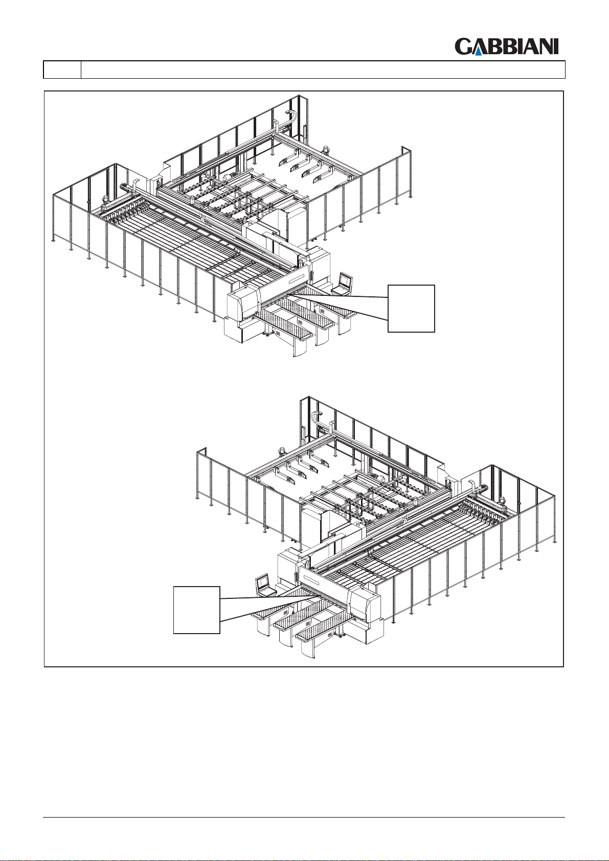
- NEVER PUT your hands under the pressure beam (zone "A" fig. 2.1).
- For any inspection or maintenance stop the machine, turn the main electric switch to 0 and
padlock it, and also set the main air valve to 0 and padlock it.
- Only authorized personnel may keep a copy of the key used for resetting the load protection
photocells.
This key must never be left in the reset control panel; instead it must be removed every time it is
used and kept by an authorized member of staff.
Cap. 2 - Pag. 2/18 THIS MANUAL IS PROPERTY OF - SCM GROUP SPA. - ANY TOTAL OR PARTIAL REPRODUCTION IS STRICTLY FORBIDDEN
Page 17
105-125
EN
2 - MACHINE SAFETY
A
A
Fig. 2.1
THIS MANUAL IS PROPERTY OF - SCM GROUP SPA. - ANY TOTAL OR PARTIAL REPRODUCTION IS STRICTLY FORBIDDEN Cap. 2 - Pag. 3/18
Page 18
105-125
2 - MACHINE SAFETY
EN
2.2 SAFETY DEVICES
(22.0)
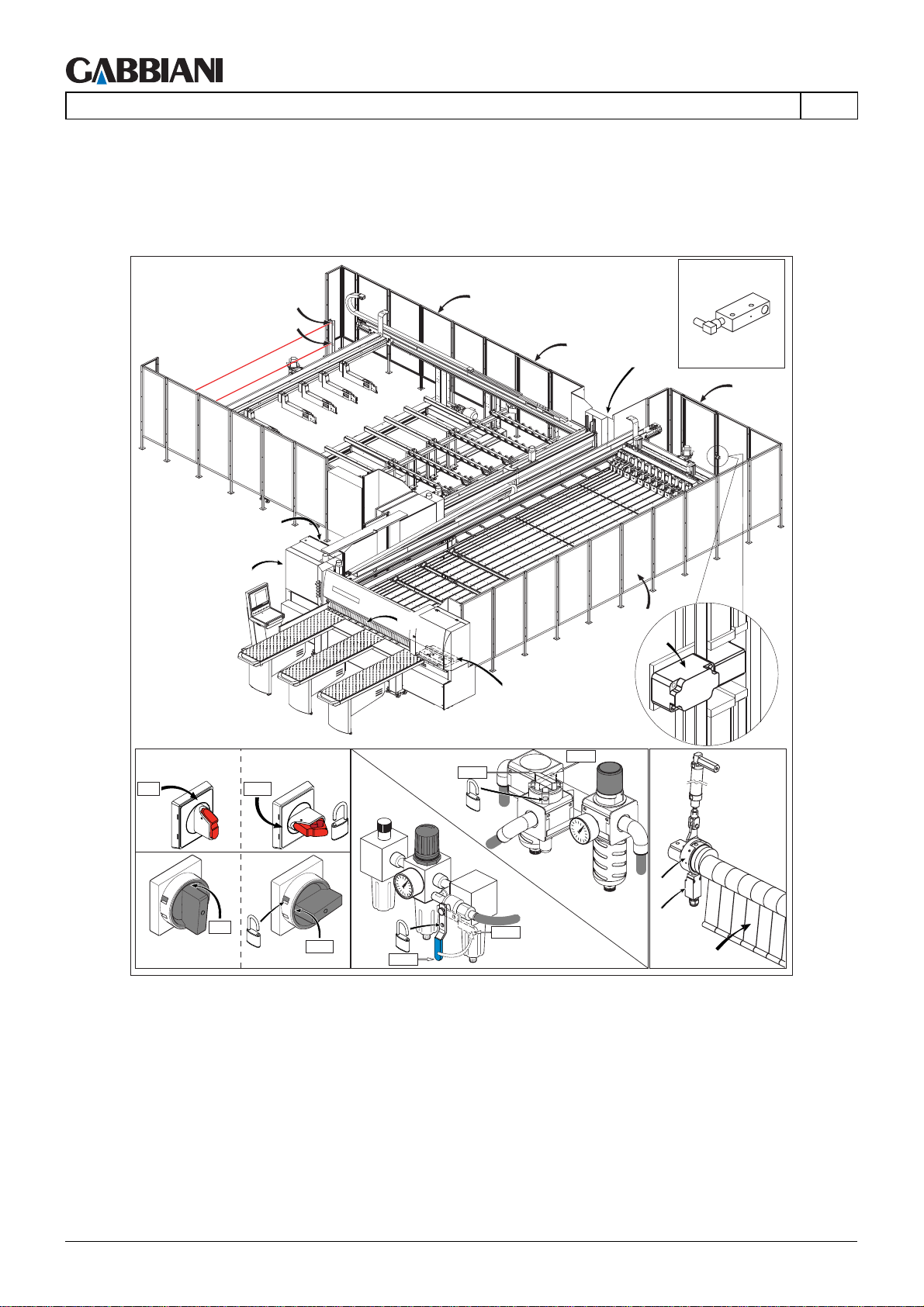
The machine is equipped with devices which guarantee the safety of the operators interacting with it during its
lifetime. These devices are illustrated and described below.
X
IE
IP
X
RP
X
H
CL
H
CS
RP
H1
CL
IE
0
I
ON
I ON
O OFF
OFF
O OFF
IE
I ON
SHUT
OPEN
IP
IE IE
cx
I
ON
0
OFF
IP
SHUT
OPEN
cy
CS
Fig. 2.2a
Cap. 2 - Pag. 4/18 THIS MANUAL IS PROPERTY OF - SCM GROUP SPA. - ANY TOTAL OR PARTIAL REPRODUCTION IS STRICTLY FORBIDDEN
Page 19
105-125
EN
X
2 - MACHINE SAFETY
H1
RP
X
X
H
CL
H
IE
IP
RP
CS
CL
IE IE
0
I
ON
I ON
O OFF
OFF
I ON
O OFF
SHUT
OPEN
IP
IE IE
cx
I
ON
0
OFF
IP
SHUT
OPEN
cy
CS
Fig. 2.2b
THIS MANUAL IS PROPERTY OF - SCM GROUP SPA. - ANY TOTAL OR PARTIAL REPRODUCTION IS STRICTLY FORBIDDEN Cap. 2 - Pag. 5/18
Page 20
105-125
2 - MACHINE SAFETY
X
X
X
X
EN
X/Y
Y
Y
FSP
Fig. 2.2c
Cap. 2 - Pag. 6/18 THIS MANUAL IS PROPERTY OF - SCM GROUP SPA. - ANY TOTAL OR PARTIAL REPRODUCTION IS STRICTLY FORBIDDEN
Page 21
105-125
2 - MACHINE SAFETY
L2a
L1a
EN
I
ON
IE IE
0
OFF
I ON
O OFF
IE IE
I
ON
I3
I1
I ON
O OFF
L1a
IP
0
OFF
RP
X2
X2
I2
Fig. 2.2d
THIS MANUAL IS PROPERTY OF - SCM GROUP SPA. - ANY TOTAL OR PARTIAL REPRODUCTION IS STRICTLY FORBIDDEN Cap. 2 - Pag. 7/18
Page 22
105-125
2 - MACHINE SAFETY
IE IE
0
I
ON
O OFF
OFF
N
I O
IE IE
EN
N
I O
O OFF
L2
I
ON
0
OFF
L1
IP
RP
Fig. 2.2e
Cap. 2 - Pag. 8/18 THIS MANUAL IS PROPERTY OF - SCM GROUP SPA. - ANY TOTAL OR PARTIAL REPRODUCTION IS STRICTLY FORBIDDEN
Page 23
105-125
2 - MACHINE SAFETY
I
ON
EN
IE IE
0
OFF
I ON
O OFF
IE IE
N
I O
O OFF
I
RP
ON
0
OFF
X2
IP
Y2
L1a
L2a
Fig. 2.2f
THIS MANUAL IS PROPERTY OF - SCM GROUP SPA. - ANY TOTAL OR PARTIAL REPRODUCTION IS STRICTLY FORBIDDEN Cap. 2 - Pag. 9/18
Page 24
105-125
2 - MACHINE SAFETY
EN
DS
BA
Fig. 2.2g
Cap. 2 - Pag. 10/18 THIS MANUAL IS PROPERTY OF - SCM GROUP SPA. - ANY TOTAL OR PARTIAL REPRODUCTION IS STRICTLY FORBIDDEN
Page 25
105-125
EN
L1b
2 - MACHINE SAFETY
L2b
Fig. 2.2h
HAZARD: The safety devices must not be removed, tampered with or deactivated for any reason
whatsoever. It is also absolutely forbidden to go beyond the safety devices without these
activating a state of emergency.
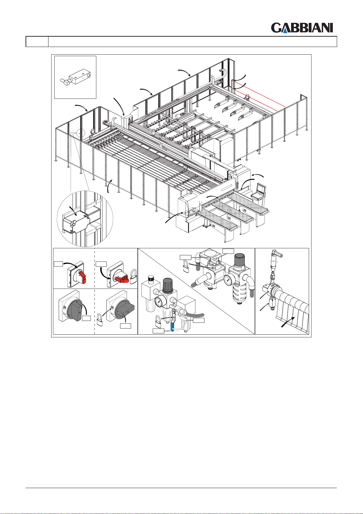
IE - Main electric switch
To disconnect the machine from the mains. It can be padlocked to block access by unauthorised persons when
carrying out adjustment, maintenance or cleaning of the machine.
IP - Pneumatic OPEN/SHUT valve
To disconnect the machine from the air supply. It can be padlocked to block access by unauthorised persons when
carrying out adjustment, maintenance or cleaning of the machine.
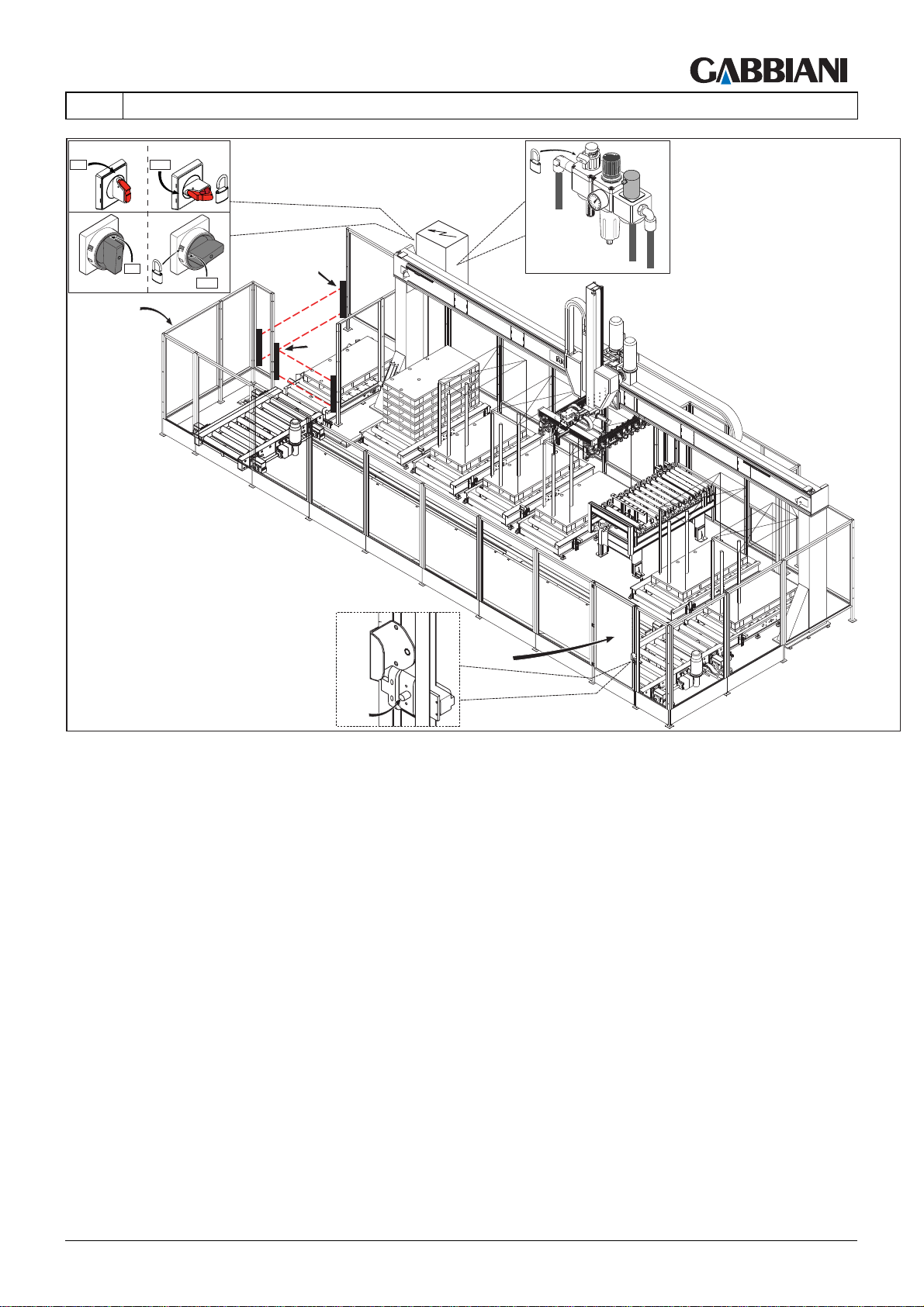
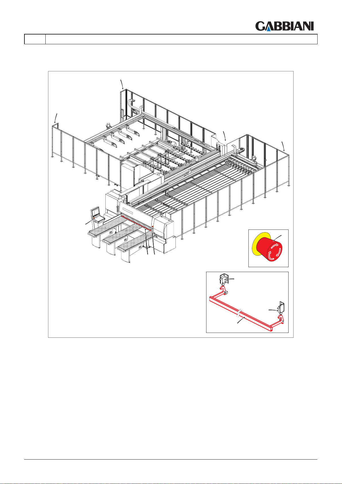
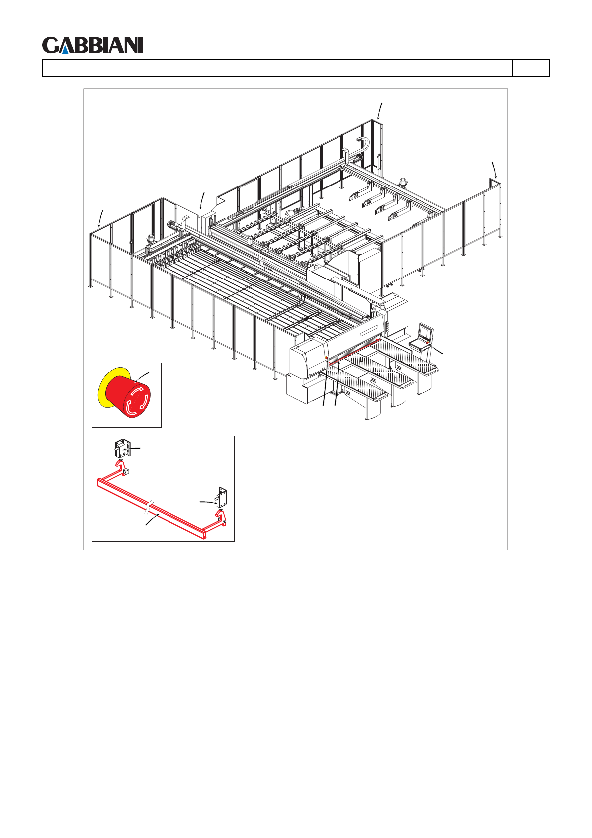
RP - Safety fences
Around the machine to hinder the operator access. The fence may be disassembled only for maintenance or
cleaning the machine. In these cases main switch "IE" and pneumatic on-off valve "IP" must be locked.
CL - Blade access guard
This cover located in the blade change zone is connected to a timed electropneumatic interlocking device which
interacts with the emergency circuit. It can only be opened if the machine is in “TOOL CHANGE” mode which can
be activated from the control panel. The interlocking device prevents
resetting the machine until the guard has been closed.
THIS MANUAL IS PROPERTY OF - SCM GROUP SPA. - ANY TOTAL OR PARTIAL REPRODUCTION IS STRICTLY FORBIDDEN Cap. 2 - Pag. 11/18
Page 26

105-125
2 - MACHINE SAFETY
CS- Sectional safety curtain:
This is a device which in its protection position prevents access to the cutting zone before the pressure bar
downstroke, avoiding accidental contact with tools. The safety screen is equipped with a cam (cx) which allows
positive activation of the limit switch (cy) which checks the position of the slats (CS). When the slats are in the
raised position the cam activates the limit switch, which prevents the automatic cutting stroke.
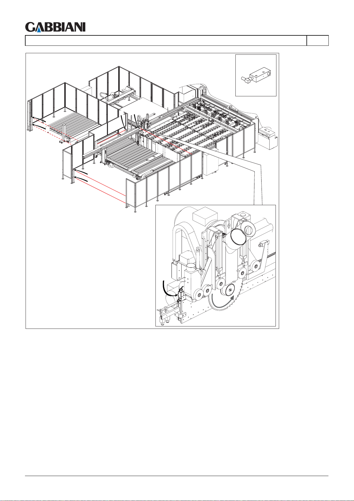
X,Y - Photoelectric safety barrier
If the machine is produced in the configuration with front loading/unloading and/or side and/or both sides, in the
areas not protected by perimeter fence there are safety photoelectric barriers with multiple individual beams. To
detect the intrusion of whole bodies, or parts of bodies, safety barriers with 2 beams are used: the heigth of the
beam from reference surface (e.g. floor) Must be 400 mm for lowest beam and 900 mm for the highest.
Barrier X:
This type of photoelectric barrier must be positioned as follows (as indicated in paragraph 4.1 for different
configurations):
- in correspondence to front loading area at a minimum distance of 850 mm from dangerous area;
- in correspondence to lateral/bilateral pre-loading areas a minimum distance from pre-loading roller conveyors is
not required. If frontal barrier "X" is interrupted the pusher stops immediately, if this is outside area "T1" (see
paragraph 4.1), of elevator table and if present pre-cutting unit if this is at a distance less than 1000 mm from front
barrier "Y"; if the "X" side/both sides barrier is interrupted the pre-loading roller conveyor stops immediately.
After carrying out operations of pre-loading or loading/unloading the barrier "X" must be manually reset, rotating a
key selector (see paragraph 5.2).
Barrier Y:
This type of photoelectric barrier must be positioned as follows (as indicated in paragraph 4.1 for different
configurations):
- in correspondence to lateral/bilateral zone, between pre-loading roller conveyor and elevator table at a distance
of 1000 mm from dangerous area;
- in correspondence to front loading area, beteween elevator table and machine benches, at a distance of 1000
mm from dangerous area (area in which pusher and pre-cutting unit may operate with barrier "X" non active).
Barrier "Y" lateral/bilateral can only be interupted with barrier "X" active, to enable the panel to pass (muting
function). If it is interupted with barrier "X" not active, the longitudinal panel saw stops immediately in emergency
stop.
The interuption of front barrier "Y" is only possible with barrier "X" active, to enable panel to pass (muting function).
Its interuption with barrier "X" not active stops longitudinal panel saw immediately in emergency stop.
EN
X1 - Photoelectric safety barrier
If the machine is in the configurations with front loading/unloading, at the zones not protected by the perimeter
fences there are photoelectric safety barriers with multiple single beams. To detect a barrier breach by the hands,
protective devices are used with a 30 mm detection capacity (64 beams): the height of the beams from the
reference surface (e.g.: the floor) must be 400 mm for the lowest beam and 1610 mm for the highest. These types
of photoelectric barriers must be positioned (as indicated in section 4.1 for the various configurations) at a
minimum distance of 150 mm from the danger zone. After loading/unloading operations have been performed the
barrier must be reset manually, by turning a keyswitch (see section 5.2). Interruption of the front barrier "X" causes
an immediate stop by the pusher, if it is outside the safety area "T1" (see section 4.1), by the elevator table and, if
present, by the pre-cutting unit if it is less than 1000 mm from the front barrier "Y".
Cap. 2 - Pag. 12/18 THIS MANUAL IS PROPERTY OF - SCM GROUP SPA. - ANY TOTAL OR PARTIAL REPRODUCTION IS STRICTLY FORBIDDEN
Page 27
105-125
EN
FSP - Precut unit safety limit switch
Safety limit switch, located on the pre-cutting unit, connected to the front photoelectric barrier "X", and interacting
with the emergency circuit. Causes an immediate stop by the pre-cutting unit if it is less than 1000 mm from the
front barrier "Y" and the front barrier "X" was interrupted.
X2,Y2 - Photoelectric safety barriers
On the automatic unloading device, at the zones not protected by the perimeter fences, there are photoelectric
safety barriers with multiple single beams. To detect a barrier breach by the whole body or parts of the body,
protective devices with 2 beams are used: the height of the beams from the reference surface (e.g.: the floor) must
be 400 mm for the lowest beam and 900 mm for the highest. After loading/unloading operations have been
performed the barriers must be reset manually, by turning a keyswitch (see paragraph 5.2).
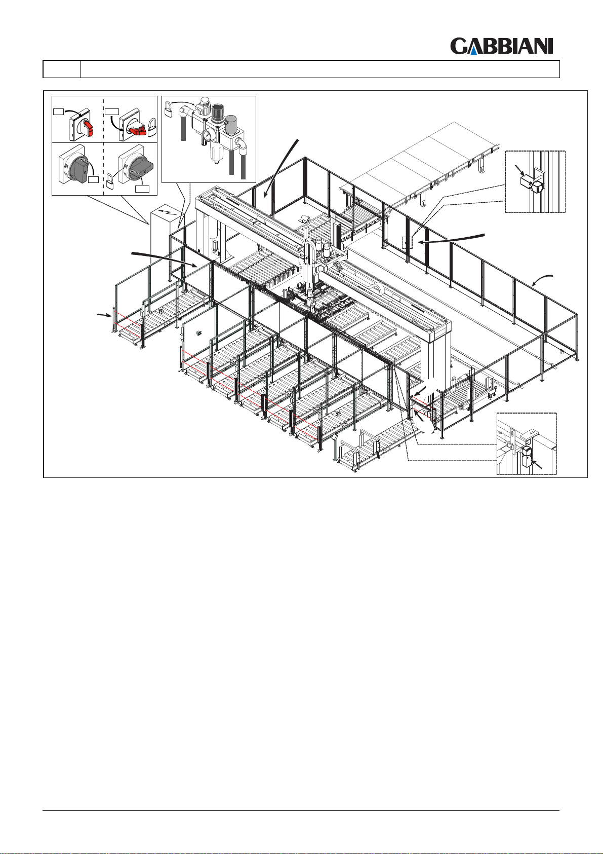
H - Manual doors
They enable access to inside the panel saw perimeter fence to carry out maintenance operations in safety. The
manual opening doors are fitted with interlocking devices with guard locks (safety mechanical limit switch with reset
knob). To open a door rotate the knob on the limit switch clockwise.
H1 - Safety limit switch
This is a safety device that activates the state of emergency, stopping the panel saw and unloading device
immediately when the access door (H) is opened.
To reset panel saw from state of emergency you must:
- ensure that no-one is inside the fence
- close the door
- reset limit switch H1 rotating the reset knob on the limit switch anti-clockwise.
- press the reset pushbutton on the control panel (see par.5.2)
2 - MACHINE SAFETY
HAZARD: It is strictly prohibited to cross the safety fence other than by the door.
I1 - Automatic door
Door with automatic opening, fitted with interlocking device without guard lock that enables automatic unloading.
I2 - Automatic door safety limit switch
Safety device (interlock advice without guard lock) loacted on automatic opening doors (I1) associated to safety
photocelectric barrier (I3) interacting on emergency circuit.
I3 - Safety photoelectric barrier with manual reset
On automatic safety device in correspondence to areas not protected by perimeter fence there are photoelectric
barriers with multiple individual beams. To detect the intrusion of whole bodies, or parts of bodies, safety barriers
with 2 beams are used: the height of the beam from reference surface (e.g. floor) Must be 400 mm for lowest beam
and 900 mm for the highest.
When the barrier is interupted when the automatic door (I1) is opened , the machine goes into a state of
emergency. After loading/unloading have been carried out the barrier must be reset manually, rotating a key
selector (see paragraph 5.2).
L1 - Manual doors
Doors at the unloading roller conveyors on the ground. Allow safe unloading. The doors, opened manually, are
fitted with an interlocking device with guard locking (mechanical safety limit switch with machine stop
electromagnet "L2"). To open a door, first press an opening request button. Once the button is pressed the gantry
terminates unloading operations and after moving to the parking zone allows the door to open. After performing
unloading operations, close the door and press the RESET button to confirm that it is closed.
L2 - Manual door safety limit switch
Safety device at the manually opened doors (L1). This is an interlocking device with guard locking (mechanical
safety limit switch with machine stop electromagnet).
THIS MANUAL IS PROPERTY OF - SCM GROUP SPA. - ANY TOTAL OR PARTIAL REPRODUCTION IS STRICTLY FORBIDDEN Cap. 2 - Pag. 13/18
Page 28

105-125
2 - MACHINE SAFETY
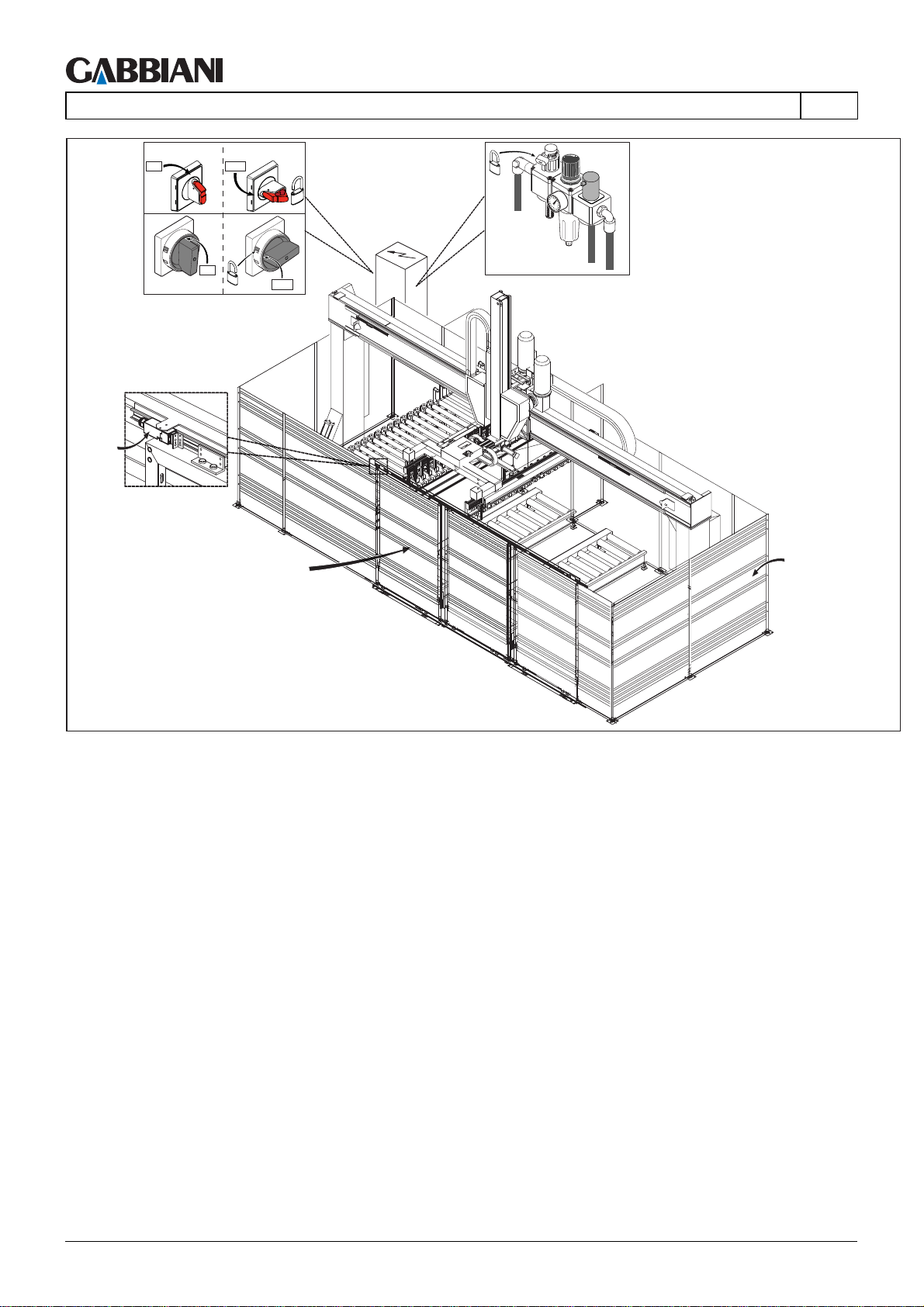
L1a - Manual doors
They enable access to inside the unloading device perimeter fence to carry out maintenance operations in safety.
The manual opening doors are fitted with interlocking devices with guard locks (safety mechanical limit switch with
reset knob). To open a door rotate the knob on the limit switch clockwise.
L2a - Manual door safety limit switch
This safety device activates the state of emergency, stopping the unloading device immediately when the access
door (L1a) is opened.
To reset unloading device from emergency stste you must:
- ensure that no-one is inside the fence
- close the door
- reset limit switch L2a rotating reset knob on it anti-clockwise.
- press reset pushbutton on control panel (see par.5.2).
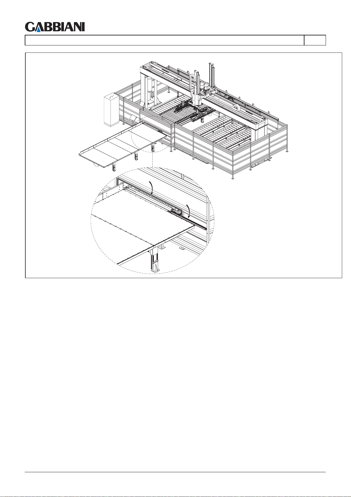
BA - Slat safety device
Prevents the risk of impact between panels coming out of the panel saw, pushed by the pusher, and the protective
fences of the unloading device. If the panels press on this slat device it activates a safety limit switch which stops
the pusher.
EN
DS - Pressure-sensitive safety device:
Prevents the risk of hands getting crushed between panels coming out of the panel saw, pushed by the pusher,
and the opening in the unloading device protective fences. Pressing on this device stops the pusher.
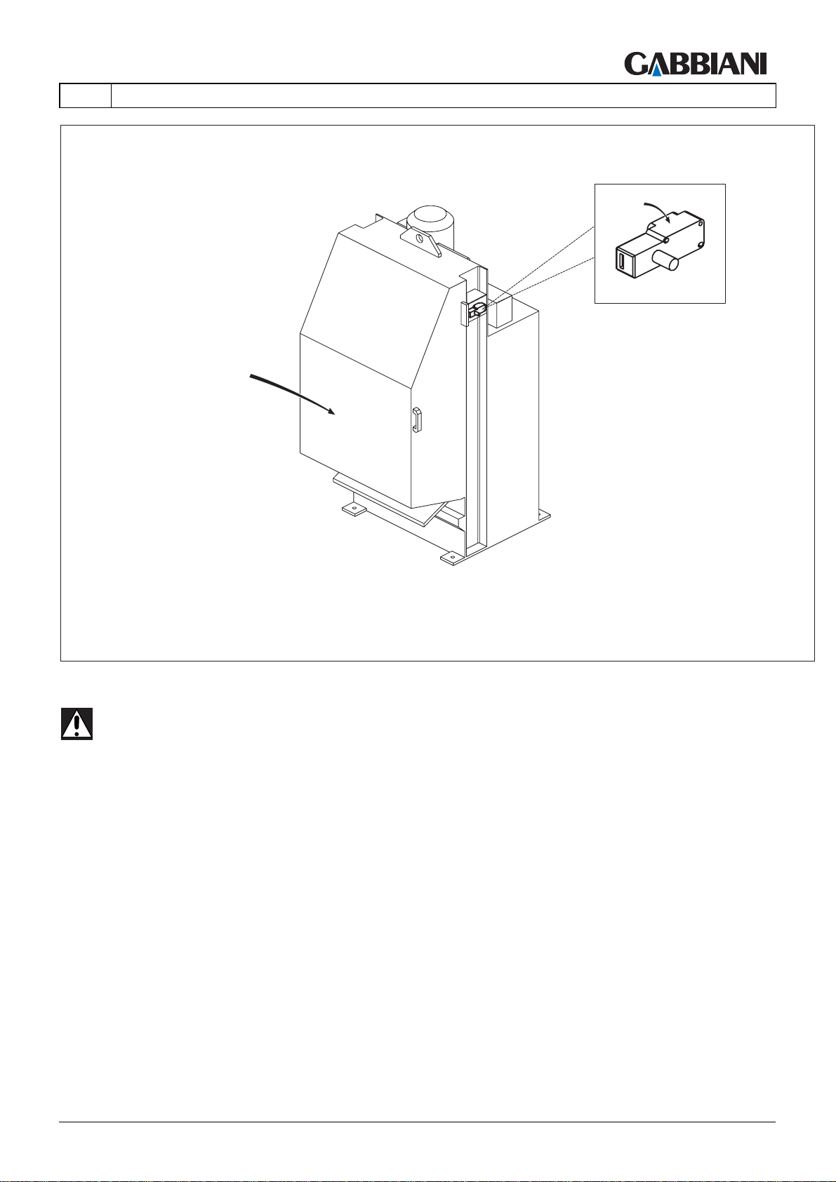
L1b - Trim cut cutter door
Allows access to the cutter for maintenance (blade changing). The manually opened door is fitted with an
interlocking device with guard locking (mechanical safety limit switch with reset knob). To open the door turn the
knob on the limit switch clockwise. After performing maintenance operations, close the door and reset limit switch
L2b by turning the reset knob on it anti-clockwise.
L2b - Trim cut cutter door safety limit switch
Safety device at the manually opened doors (L1b). This is an interlocking device with guard locking (mechanical
safety limit switch with reset knob).
Cap. 2 - Pag. 14/18 THIS MANUAL IS PROPERTY OF - SCM GROUP SPA. - ANY TOTAL OR PARTIAL REPRODUCTION IS STRICTLY FORBIDDEN
Page 29
105-125
EN
2 - MACHINE SAFETY
2.3 EMERGENCY DEVICES
(23.0)
M
M
M
M
M
M
N
M
N1
N1
N
Fig. 2.3a
THIS MANUAL IS PROPERTY OF - SCM GROUP SPA. - ANY TOTAL OR PARTIAL REPRODUCTION IS STRICTLY FORBIDDEN Cap. 2 - Pag. 15/18
Page 30
105-125
2 - MACHINE SAFETY
M
EN
M
M
M
M
M
N
M
N1
N1
N
Fig. 2.3b
Cap. 2 - Pag. 16/18 THIS MANUAL IS PROPERTY OF - SCM GROUP SPA. - ANY TOTAL OR PARTIAL REPRODUCTION IS STRICTLY FORBIDDEN
Page 31
105-125
EN
NOTE: When an emergency is activated activation the power supply to the control circuit and the
auxiliaries only is cut.
M - Emergency stop pushbuttons
Located at various points, these allow the machine to be stopped immediately in case of imminent risk. To reset,
turn the emergency button and then press the reset button (see paragraph 5.2) on the main control panel.
N - Sensitive pressure bar (Hand protection emergency bar)
Protects the operator's hands from crushing in the cutting zone by activating device N1 and stopping the machine,
with inversion of the presser downstroke direction of movement and blade retraction under the worktable.
2 - MACHINE SAFETY
THIS MANUAL IS PROPERTY OF - SCM GROUP SPA. - ANY TOTAL OR PARTIAL REPRODUCTION IS STRICTLY FORBIDDEN Cap. 2 - Pag. 17/18
Page 32

105-125
2 - MACHINE SAFETY
EN
2.4 RESIDUAL RISKS
(24.1)
Although they comply with all safety standards, the following risks exist:
1 - risk of inhaling dust, if using machine without extraction;
2 - risk of squashing operator, if objects are deposited (e.g. stacks of panels) in the area withing safety distance "S"
(see paragraph 4.1);
3 - risk of contact with elements containing electric current, in case of failure to set main ON/OFF switch to 0 OFF
and padlock it before carrying out any maintenance that require opening safety guards with identification plate
saying "danger electric current" (see paragraph 1.4.2);
4 - risk of persons being trapped inside perimeter fence, if the interlocked access doors are closed without
ensuring that there is no-one inside the machine;
5 - risk of cutting due to contact with blades while changing them due to failure to wear safety gloves while handling
the blades;
6 - risk of cutting due to contact with blades, of the safety curtain is lifted and passed through;
7 - risk that during maintenance the operator will be crushed under the panel transfer device due to its sudden
descent if the tap is opened to drain the compressed air tank with the parking brake off.
Cap. 2 - Pag. 18/18 THIS MANUAL IS PROPERTY OF - SCM GROUP SPA. - ANY TOTAL OR PARTIAL REPRODUCTION IS STRICTLY FORBIDDEN
Page 33

105-125
EN
3 - TECHNICAL SPECIFICATIONS
INDEX
3.1 TECHNICAL SPECIFICATIONS (STANDARD MACHINE) .......................2
3.2 OPTIONALS............................................................................................... 3
3.3 OPTIONAL UNITS-DESCRIPTION............................................................ 4
3.4 NOISE EMISSION......................................................................................9
THIS MANUAL IS PROPERTY OF - SCM GROUP SPA. - ANY TOTAL OR PARTIAL REPRODUCTION IS STRICTLY FORBIDDEN Cap. 3 - Pag. 1/10
Page 34
105-125
3 - TECHNICAL SPECIFICATIONS
EN
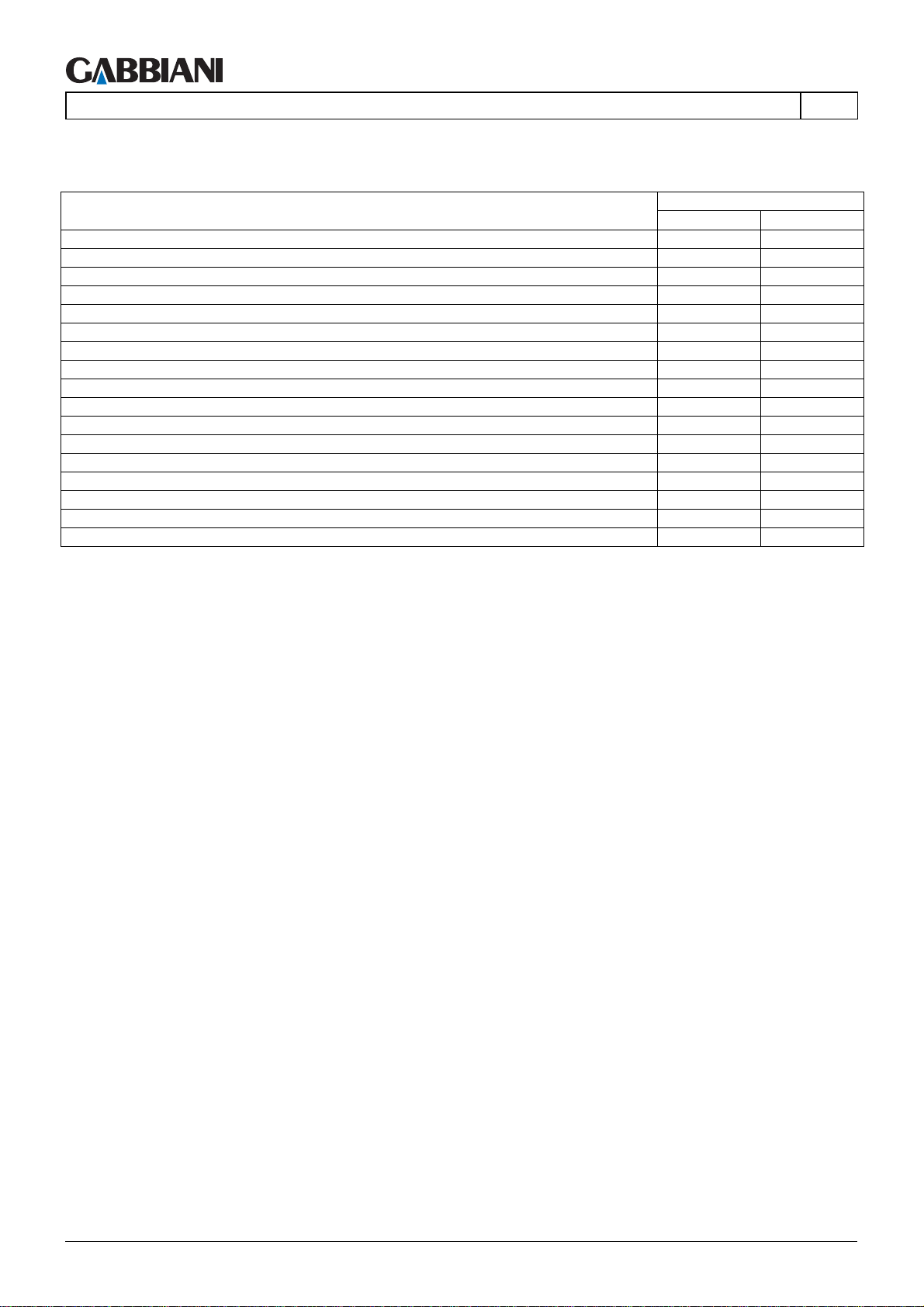
3.1 TECHNICAL SPECIFICATIONS (STANDARD MACHINE)
(31.0)
Model TECHNICAL DETAILS (STANDARD MACHINE)
105 125
Main blade maximum projection [mm] 105 125
Blade min./max. diameter [mm] 300/380 300/420
Blade min./max. speed of rotation [rpm] 1000/3500 1000/3500
Scoring saw min./max. diameter [mm] 160/160 160/160
Scoring saw min./max. speed of rotation [rpm] 3000/7000 3000/7000
Blades min./max. feed speed [m/min] 0/120 0/120
Main blade motor power [kW] 15 15
Scoring saw motor power [kW] 1.5 1.5
Pusher maximum feed speed [m/min] 24 24
Pusher maximum return speed [m/min] 55 80
Double Side aligner on presser belt YES YES
Mechanical or pneumatic blade and scoring saw locking YES YES
Capacity of lifting platform with crossbars [kg] 4000 4000
Capacity height with lifting platform fitted with support crossbars [mm] 600 600
Capacity height with lifting table fitted with support rollers [mm] 600 600
Lifting platform upstroke/downstroke speed [m/min] 0,75 0,75
Front loading on lifting platform with crossbars YES YES
Cap. 3 - Pag. 2/10 THIS MANUAL IS PROPERTY OF - SCM GROUP SPA. - ANY TOTAL OR PARTIAL REPRODUCTION IS STRICTLY FORBIDDEN
Page 35

105-125
EN
3 - TECHNICAL SPECIFICATIONS
3.2 OPTIONALS
(32.0)
Model OPTIONALS
105 125
Main blade motor power up to 19 kW; speed of rotation up to 5.000 rpm YES YES
Inverter for speed adjustment of the main saw blade uo to 5.000 rpm YES YES
Scoring saw motor power up to 2,2 kW; scoring saw blade diameter up to 300 mm YES YES
Postforming unit, pneumatically or electrically actuated YES YES
Cutting lenght of the longitudinal saw up to 5.800 mm YES YES
Cutting lenght of the trasversal saw up to 2.500 mm YES YES
Left configuration YES YES
Air cushion tables with different dimensions YES YES
Blade carriage forward/return speed up to 150 m/min YES YES
Main saw blade and scoring saw blade mounted on different carriages of the saw unit YES YES
Limitation of the saw blade vertical raise, manual or power driven YES YES
Blade cooling with air YES YES
Optimised pressure beam raise YES YES
Laser for cutting line detection YES YES
Pusher return speed up to 130 m/min at trasversal cut YES YES
Pusher return speed up to 70 m/min at longitudinal cut YES YES
Bridge to close the gaps between the clamping devices on pusher YES YES
Loading/unloading from maschines left and/or right side YES YES
Trimming management trapdoor in front of the cutting line of the transversal saw YES YES
Command panel on independent console with cable lenght up to 2 m YES YES
Lateral aligners for the transversal saw YES YES
Single activated clamping devices at the pusher of the longitudinal saw YES YES
Pre-cut saw unit with fixed or rotating table YES YES
Device for manual or automatic loading of thin panel YES YES
Loading table with height of panels up to 1300 mm YES YES
Vacuum panel lifter, for loading panels from the loading table to the machine table YES YES
Panel detachment device YES YES
Panel thickness detector YES YES
Pushing out device of the transversal saw YES YES
Rotating device of the longitudinal saw YES YES
Rotary conveyor for loading/unloading YES YES
Unloading device in the front side of the machine YES YES
Extractor device with set down table inside protected area YES YES
Trim cut conveyor and cutting devices (rotary case for trim cut containment and unloading,
vibrating conveyor belt, trim cut cutter, tilting conveyor belt)
Compact loading area YES YES
Blades unlocking with pneumatic selector YES YES
Loading table for stacks of panels with maximum weight up to 7000 kg YES YES
Loading table with vertical upstroke speed, inverter-controlled, of up to 1.5 m/min YES YES
Device mounted on pressure bar to reduce dust emissions YES YES
YES YES
THIS MANUAL IS PROPERTY OF - SCM GROUP SPA. - ANY TOTAL OR PARTIAL REPRODUCTION IS STRICTLY FORBIDDEN Cap. 3 - Pag. 3/10
Page 36

105-125
3 - TECHNICAL SPECIFICATIONS
EN
3.3 OPTIONAL UNITS-DESCRIPTION
(33.0)
Main blade motor power up to 19 kW; speed of rotation up to 5.000 rpm
Inverter for speed adjustment of the main saw blade uo to 5.000 rpm: varies the blade rotation speed according to
the type or quantity of panels being cut.
Scoring saw motor power up to 2,2 kW; scoring saw blade diameter up to 300 mm
Postforming unit, pneumatically or electrically actuated: Device that allows the panel to be scored laterally,
stopping the blade chips exiting from the side of the piece.
Air cushion table: present in variable quantities and sizes, can be installed in loading/unloading zone to allow
handling of panels or panel packs.
Blade carriage forward/return speed up to 150 m/min
Main saw blade and scoring saw blade mounted on different carriages of the saw unit: the main and scoring blade
carriage have independent raise.
Limitation of the saw blade vertical raise, manual or power driven
- Manual blade adjustment. Device for the execution of grooves (blind cuts) whose depth is adjusted by the
operator through the adjustment of the saw blade carriage.
- Electronic blade adjustment: Electronic control device for regulating the vertical position of the main cutting blade,
limiting its excursion in order to cut slots (blind cuts) where the user regulates the depth by entering a series of
values via the on-board computer.
- Electronic scoring adjustment: Electronic control device for the vertical and transversal positioning of the scoring
blade, according to the values entered by the user in the machine side PC.
Blade air cooling: device which uses a jet of compressed air to cool the blade.
Optimised pressure beam and blade raise. Device for the adjustment of the blade and pressor belt raise according
to the height of the pack being cut.
Laser for cutting line detection: Reference laser light to view the blade path along the cutting axis.
Pusher return speed up to 130 m/min at trasversal cut
Pusher return speed up to 70 m/min at longitudinal cut
Bridge to close the gaps between the clamping devices on pusher: device for workpieces tight; allows the
movement of workpieces of width smaller than the distance between centres of the grippers.
Trimming management trapdoor in front of the cutting line of the transversal saw: trapdoor situated in front of the
cutting line that allows the discharge of head and tail trimmings.
Control panel on independent console: allows the operator to position the mobile control panel in the most
comfortable position.
Cap. 3 - Pag. 4/10 THIS MANUAL IS PROPERTY OF - SCM GROUP SPA. - ANY TOTAL OR PARTIAL REPRODUCTION IS STRICTLY FORBIDDEN
Page 37

105-125
EN
Lateral aligner for the transversal saw: lateral aligner situated in front of the cutting line of the transversal saw, it is
used to favour the alignment of panels of considerable weight. The panels can be aligned for l>350mm.
Single activated clamping devices at the pusher of the longitudinal saw: Device for the automatic exclusion of
grippers. It allows the pusher return to the loading position without having to delay the elevator table raise.
Pre-cut saw unit with fixed or rotating table:
System for pre-cutting automatic management. The system consists of:
- an external carpeted table, fixed or rotary to allow rotation of the pre-cut pack through 90°;
- a unit for the unfinished cut which runs on recirculating ball screw prismatic guides. Unit movement with rack and
pinion system. Pneumatic blade change and independent extractor hood.
- Wood guide unit for pre-cut panel insertion and extraction.
- Compacting station with omnidirectional wheels on the machine table with retractable front aligners.
The device allows automatic recirculation of the pre-cut parts to allow both logic and differentiated cuts.
Pre-cut parts are recirculated and rotated in masked time during the cycle time, guaranteeing high productivity.
Thin panels manual loading device: device that allows the manual loading of thin panels, through a remote mobile
control panel, close to the elevator table.
Thin panels automatic loading device: device that allowsthe loading of thin panels, guaranteeing functioning
continuityand reliability in the automatic loading operations of the panelsaw.
3 - TECHNICAL SPECIFICATIONS
Loading table with height of panels up to 1300 mm
Vacuum panel lifter, for loading panels from the loading table to the machine table: device used to load thin panels;
this picks up the single sheet from the elevator table and deposits it on the machine table.
Thin panels detachment device: device that completely detaches the sheet to be picked up from the rest of the
stack on the elevator table.
Panel thickness gauge: Device located on the suction cup pusher. Allows measurement of the thickness of the
panels picked up using two mechanical feelers and compares this value with the value set via the software.
Pushing out device: device which allows expulsion of whole panels or offcuts from the machine table to beyond the
cutting axis.
Pinza lunga: device which allows expulsion of whole panels or offcuts from the machine table to beyond the cutting
axis.
Rotating device of the longitudinal saw: allows automatic precut management. The system consists of:
- a strong metal frame supporting the stack of panels during rotation;
- a pneumatic and electromechanical system for lifting and rotating the stack of panels.
The main pusher automatically loads the pack of panels from the rear loading table (reference at centre of table)
and moves it to the centre of the turntable. The system automatically manages the cutting of the "Slave" section
and re-insertion and rotation of the Master part.
Rotary conveyor for loading/unloading: Allows fork-lift trucks to place the stack of panels on the roller conveyor on
the right or left of the machine instead of at the back. Once the stack has been put in position, the operator can
issue the command to rotate the roller conveyor through 90 degrees, bringing it to the machine loading position.
This solution is used when there isn't enough space for the fork-lift trucks to manoeuvre at the back of the panel
saw.
Unloading device in the front side of the machine (bridge)
The unloading device may consist of the following functional sub-units:
THIS MANUAL IS PROPERTY OF - SCM GROUP SPA. - ANY TOTAL OR PARTIAL REPRODUCTION IS STRICTLY FORBIDDEN Cap. 3 - Pag. 5/10
Page 38
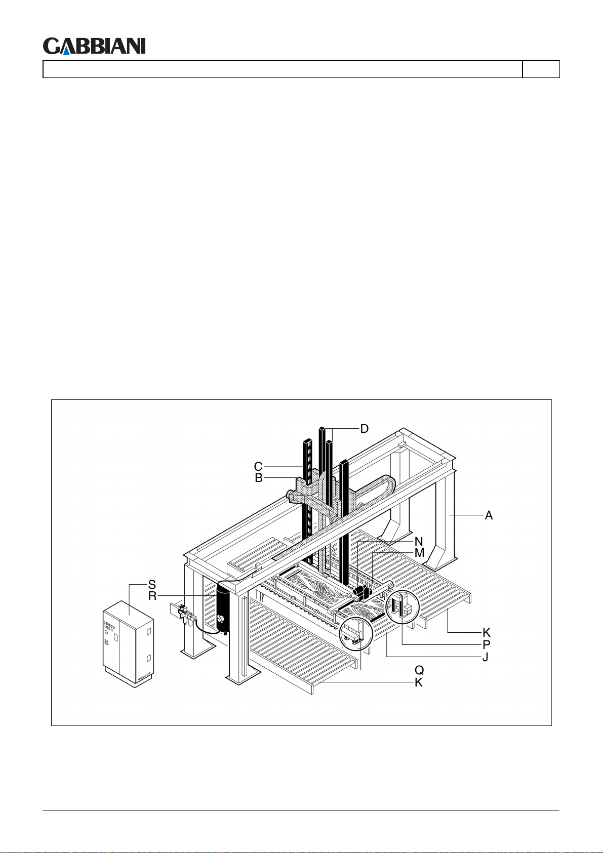
105-125
3 - TECHNICAL SPECIFICATIONS
A - Structure:
supports units for moving panels.
B - Carriage:
transports the panels.
C - Tubes:
support gripper holder frame M.
D - Compensation cylinders:
these facilitate gripper frame vertical movement M.
J - Longitudinal conveyor
Transports panels from panel saw to automatic unloader
K- Stacking/unloading roller conveyor.
Roller conveyor on which the panels are stacked before being unloaded (a maximum number of 30 stacks may be
present)
M - Self-centring gripper frame with unloading function (model 250/P):
picks up the panel from longitudinal conveyor J and unloads it on stacking benches K.
N - Motor driven device for adjusting opening of gripper arms (model 250/P):
they adjust the position of the grippers on the basis of panel dimensions.
P - Pneumatic grippers (model 250/P):
push and release the panel to be moved.
Q - Pallet (model 250/P):
support the panel underneath during movement.
R - Compressed air tank:
feeds air to pneumatic equipment.
S - Control panel:
operates and checks machine functions.
EN
Fig. 3.3a
Extractor devices and set down table inside the protected area: devices located inside the perimeter fence which
allow extraction and accumulation of the strips of panels outside the transversal panel saw. The strips are then fed
Cap. 3 - Pag. 6/10 THIS MANUAL IS PROPERTY OF - SCM GROUP SPA. - ANY TOTAL OR PARTIAL REPRODUCTION IS STRICTLY FORBIDDEN
Page 39
105-125
EN
into the transversal panel saw again using a pusher system; they are then realigned with the transversal cutting
axis.
Notes:
- maximum strip accumulation width: 1200 mm
- minimum individual strip width: 80 mm
- the strips must be of the same length
- the height of the packs of strips must be the same.
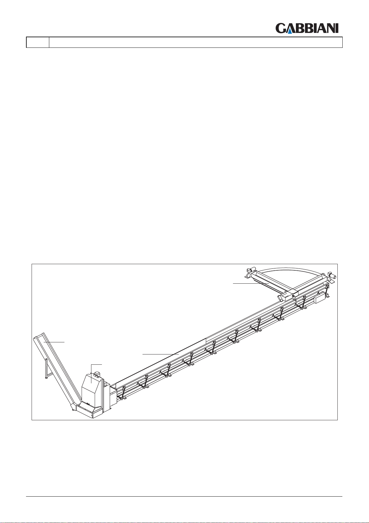
Trim cut conveyor and cutting devices (rotary case for trim cut containment and unloading, vibrating conveyor belt,
trim cut cutter, tilting conveyor belt)
A - Rotary case for trim cut containment and unloading
A case for containing wood shavings, screwed to the floor, with a pneumatically-controlled door on the base for
unloading the shavings. Shavings from the transversal panel saw are conveyed to the containment case: at the
end of each cycle the panel saw provides consent for the containment case to rotate through 90° and its shavings
unloading door to open. The shavings drop onto the vibrating conveyor belt below, extending as far as under the
longitudinal panel saw cutting axis.
B - Vibrating conveyor belt
A conveyor system which allows slow movement of wooden strips. It consists of a long tray, mounted on oscillating
suspension devices, and a motor which uses a belt and a cam support to supply a wave-like movement, for the
slow transfer of materials placed in the tray.
C - Trim cut cutter
A cutter for cutting offcuts. Can cut small strips of chipboard, MDF or even solid wood, provided the dimensions of
the workpieces are within those specified for the machine.
D - Tilting conveyor belt
A conveyor system for picking up material to be conveyed to a low point, after which the workpiece is conveyed to
a predetermined height then allowed to descend, under the force of gravity, into a collection container.
3 - TECHNICAL SPECIFICATIONS
A
D
B
C
Fig. 3.3b
Compact loading area: If the machine is in the configurations with front loading/unloading, at the zones not
protected by the perimeter fences there are photoelectric safety barriers with multiple single beams. The standard
version uses photoelectric barriers with 2 beams, able to detect a barrier breach by the whole body or parts of it.
These types of barriers must be positioned, in the front loading zone, at a minimum distance of 850 mm from the
danger zone. There are optional photoelectric barriers with a 30 mm detection capacity, able to detect a barrier
breach by the hands. These types of barriers may be positioned at a minimum distance of 150 mm from the danger
zone. They therefore allow a compact loading area of around 700 mm.
THIS MANUAL IS PROPERTY OF - SCM GROUP SPA. - ANY TOTAL OR PARTIAL REPRODUCTION IS STRICTLY FORBIDDEN Cap. 3 - Pag. 7/10
Page 40

105-125
3 - TECHNICAL SPECIFICATIONS
EN
Blades unlocking with pneumatic selector: for rapid blade locking and release using a pneumatic selector (see
paragraph 6.4.0).
Loading table for stacks of panels with maximum weight of up to 7000 kg: loading table with larger structure for
loading stacks of panels with maximum weight of up to 7000 kg.
Loading table with inverter-controlled vertical upstroke speed of up to 1.5 m/min.: loading table with motor for
inverter-controlled vertical lifting; allows a vertical upstroke speed of up to 1.5 m/min.
Device mounted on the pressure bar to reduce dust emissions: pneumatically-operated mobile metal structure at
the longitudinal and transversal station presser outfeed. During the front end trim cut phase this device allows
optimum shavings extraction and guarantees greater machine cleanness and minimum dust dispersion in the air.
Uninterruptible power supplies: Safety device that ensures the correct functioning for a set period of the machine
side personal computer in case of no voltage.
OTTIMO software: cuts optimisation software.
Labelling machine: Labels printer to be connected to the machine side PC; it prints a label for every workpiece
produced or for every group.
Offcut unloading container (manual removal): Container with swivelling wheels for collection and removal of the
offcuts under the trapdoor. Container movement is manual.
Chap. 3 - Page 8/10 THIS MANUAL IS PROPERTY OF - SCM GROUP SPA. - ANY TOTAL OR PARTIAL REPRODUCTION IS STRICTLY FORBIDDEN
Page 41
105-125
EN
3 - TECHNICAL SPECIFICATIONS
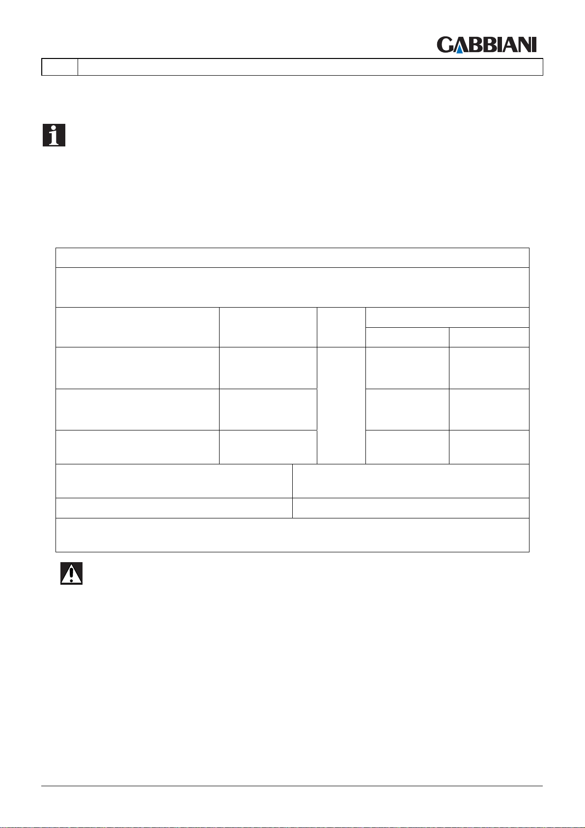
3.4 NOISE EMISSION
(34.0)
NOTE
"The figures quoted are emission levels and are not necessarily safe working levels. Whilst there is
a correlation between the emission and exposure levels, this cannot be used reliably to determine
whether or not further precautions are required. Factors that influence the actual level of exposure
of the workforce include the characteristics of the work room, the other sources of noise, etc. i.e.
the number of machines and other adjacent processes. Also the permissible exposure level can
vary from country to country. This information, however, will enable the user of the machine to
make a better evaluation of the hazard and risk".
NOISE EMISSION
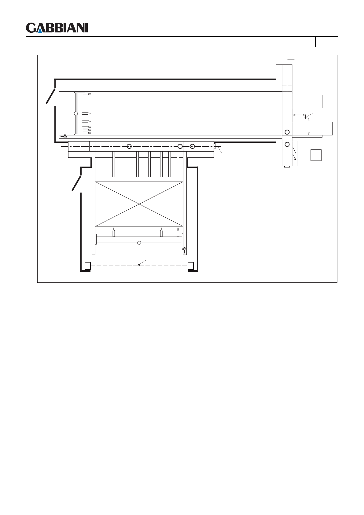
Function: PANEL CUTTING - Norm ISO 7960-95, Annex P
R.d.P CSR n° 07032
Lop. E: Level of sound
pressure at loading area
operator position TL dB(A)
Lop. U: Level of sound
pressare at cutting area
operator position TT dB(A)
Lw: Noise emission level
dB(A) / mW(A)
Reference norm
EN ISO
11202:1997
EN ISO
11202:1997
EN ISO
3746:1995
Maximum value of instantaneous acoustic
pressureC at working positions
Constant
K
4
< 130 dB(A) (Directive 98/37/CE)
PANEL CUTTING
VSA LAV
73.0 76.3
81.0 82.5
97.5 / 5.6 100.5 / 11.3
VSA : Idle working without suction LAV : Durino operation with suction
The values listed above apply to "free area" conditions, in accordance with the test
methods envisaged by the reference standard.
DANGER-WARNING: Wear ear defenders to protect your hearing.
THIS MANUAL IS PROPERTY OF - SCM GROUP SPA. - ANY TOTAL OR PARTIAL REPRODUCTION IS STRICTLY FORBIDDEN Cap. 3 - Pag. 9/10
Page 42
105-125
3 - TECHNICAL SPECIFICATIONS
TL
TT
500
EN
op. U
800
op. E
Cap. 3 - Pag. 10/10 THIS MANUAL IS PROPERTY OF - SCM GROUP SPA. - ANY TOTAL OR PARTIAL REPRODUCTION IS STRICTLY FORBIDDEN
Page 43

105-125
EN
4 - TRANSPORT AND INSTALLATION
INDEX
4.1 MACHINE INSTALLATION ........................................................................ 2
4.2 TRANSPORT, PACKAGING AND UNPACKING..................................... 46
4.3 MOVING THE MACHINE .........................................................................52
4.4 FIXING TO THE FLOOR (Fig. 4.4) ..........................................................64
4.5 ELEMENT ASSEMBLY, REMOVAL OF LOCKS AND LEVELLING ........ 65
4.6 CONNECTING UP THE POWER SUPPLY (Fig. 4.6).............................. 74
4.7 CONNECTING UP THE AIR SUPPLY (Fig. 4.7-4.7a) .............................77
4.8 SUCTION CONNECTION (Fig. 4.8)......................................................... 78
THIS MANUAL IS PROPERTY OF - SCM GROUP SPA. - ANY TOTAL OR PARTIAL REPRODUCTION IS STRICTLY FORBIDDEN Cap. 4 - Pag. 1/79
Page 44
105-125
4 - TRANSPORT AND INSTALLATION
EN
4.1 MACHINE INSTALLATION
(411.0)
CAUTION
- Installation must be carried out by the manufacturer's technicians or technicians authorised by
the manufacturer.
- There must always be two persons to carry out installation operations.
- Any handling of the machine or parts of it must be carried out by operators authorised to use
handling machines or equipment (lift trucks, cranes, etc.).
- The installation operations must be carried out by skilled technicians (removal of locks,
assembly, levelling, air, suction and electrical connections).
- It is important to study the operations in the use and maintenance manual (this manual) before
carrying them out on the machine.
- Always check that the machinery and equipment to be used are working efficiently.
Check that the floor is solid, stabile and level.
For correct dimensioning of the foundation use the data provided:
- total weight of machine body (see machine identification plate)
- maximum load on a single foot (D=90mm) = 1000 kg
- maximum differential yielding allowed = 0.02 mm/m
NOTE: Please refer to the lay-out provided with the machine for the overall dimensions and the
actual assembly positions.
Cap. 4 - Pag. 2/79 THIS MANUAL IS PROPERTY OF - SCM GROUP SPA. - ANY TOTAL OR PARTIAL REPRODUCTION IS STRICTLY FORBIDDEN
Page 45

105-125
EN
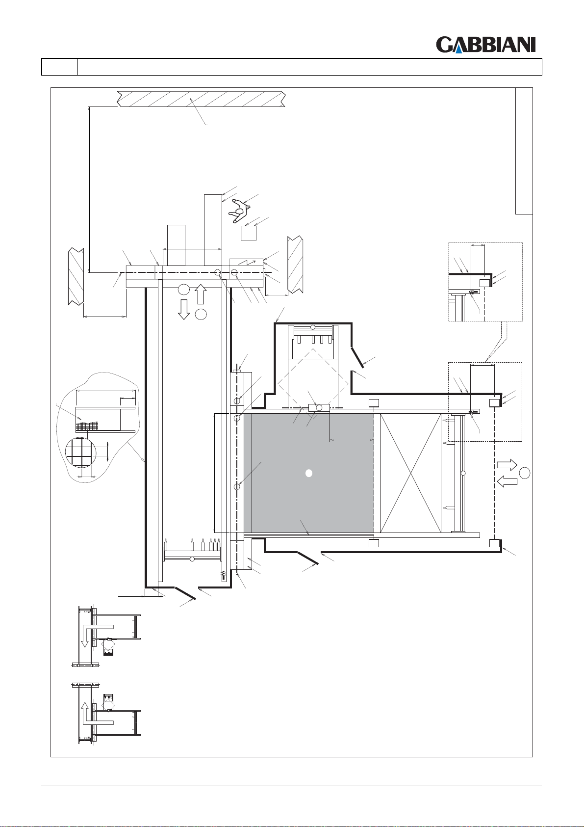
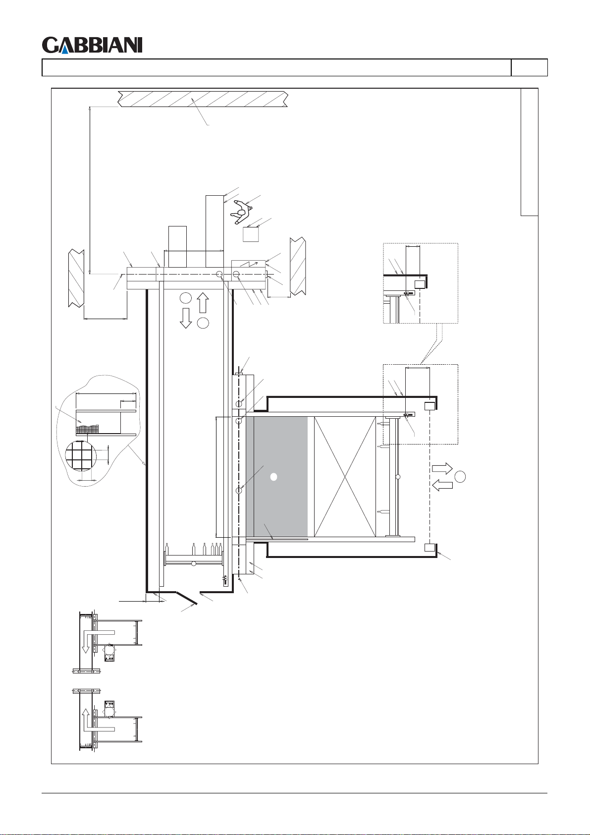
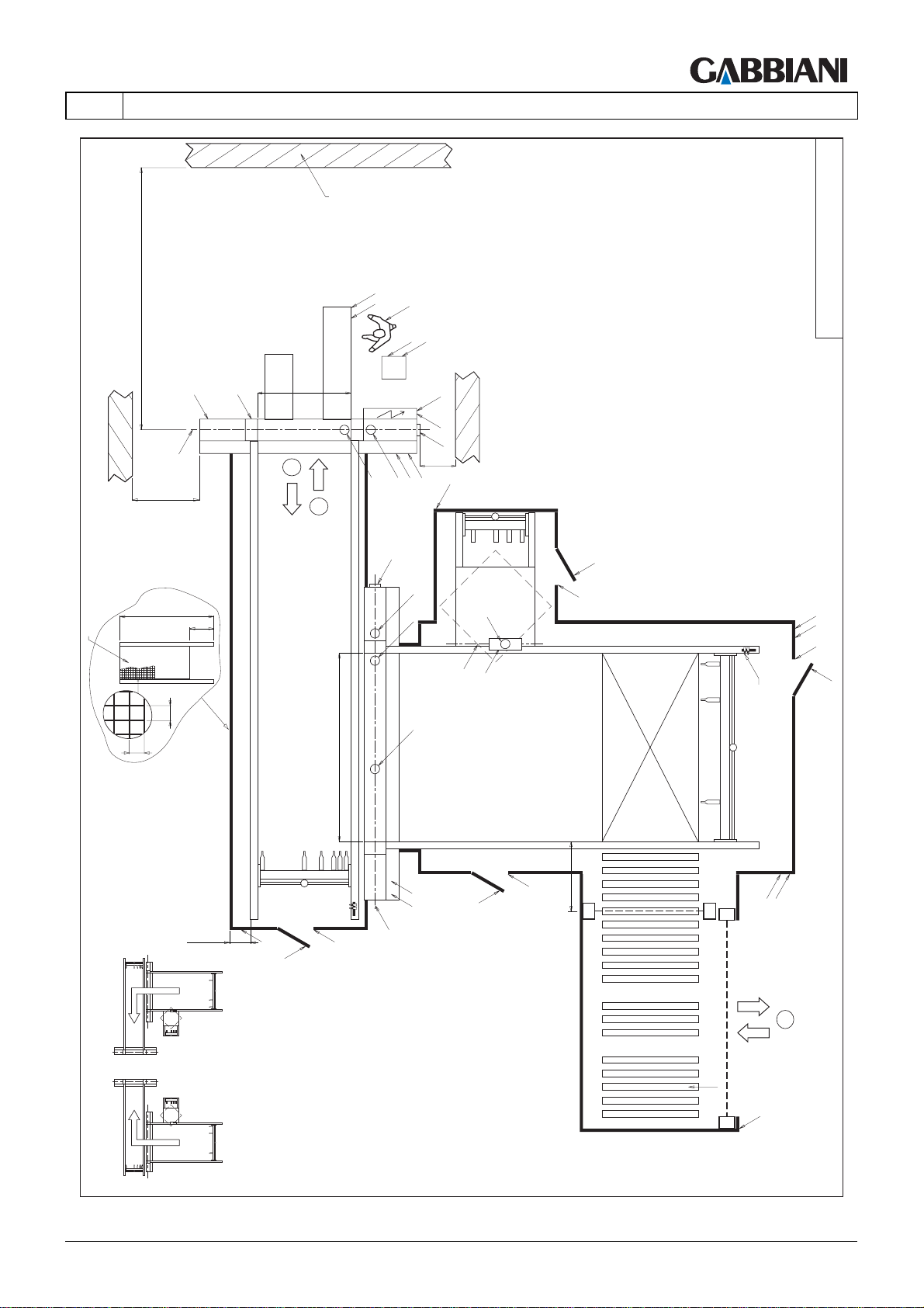
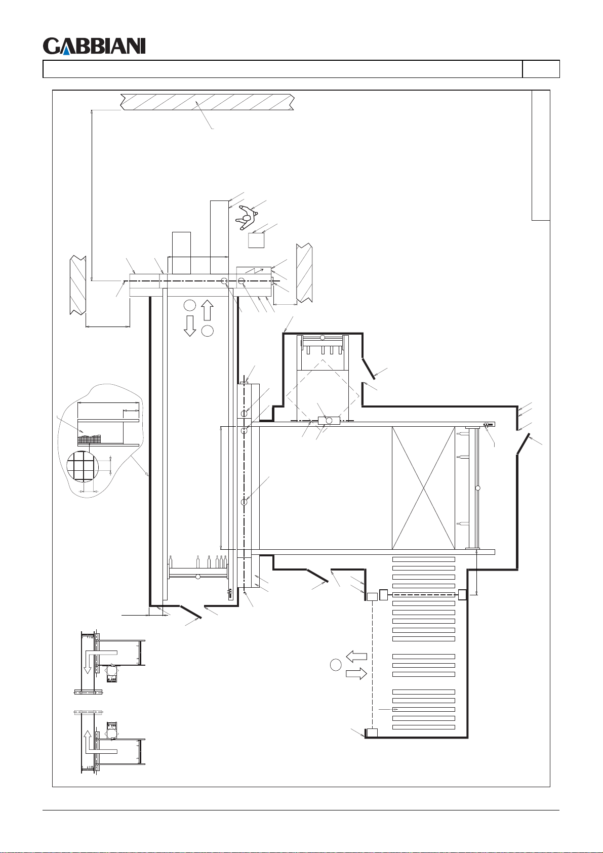
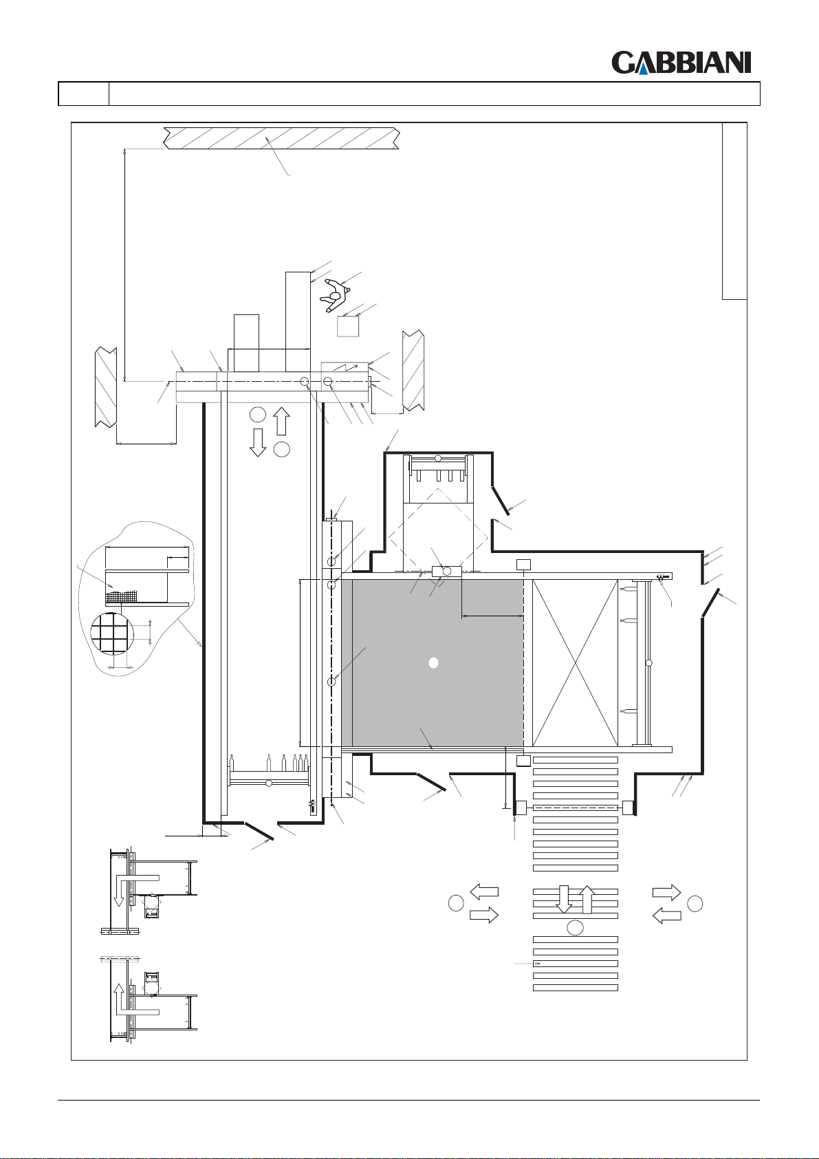
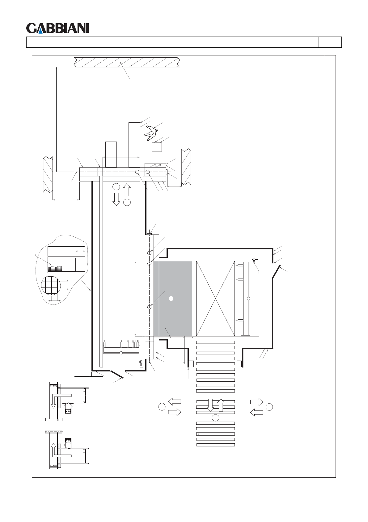
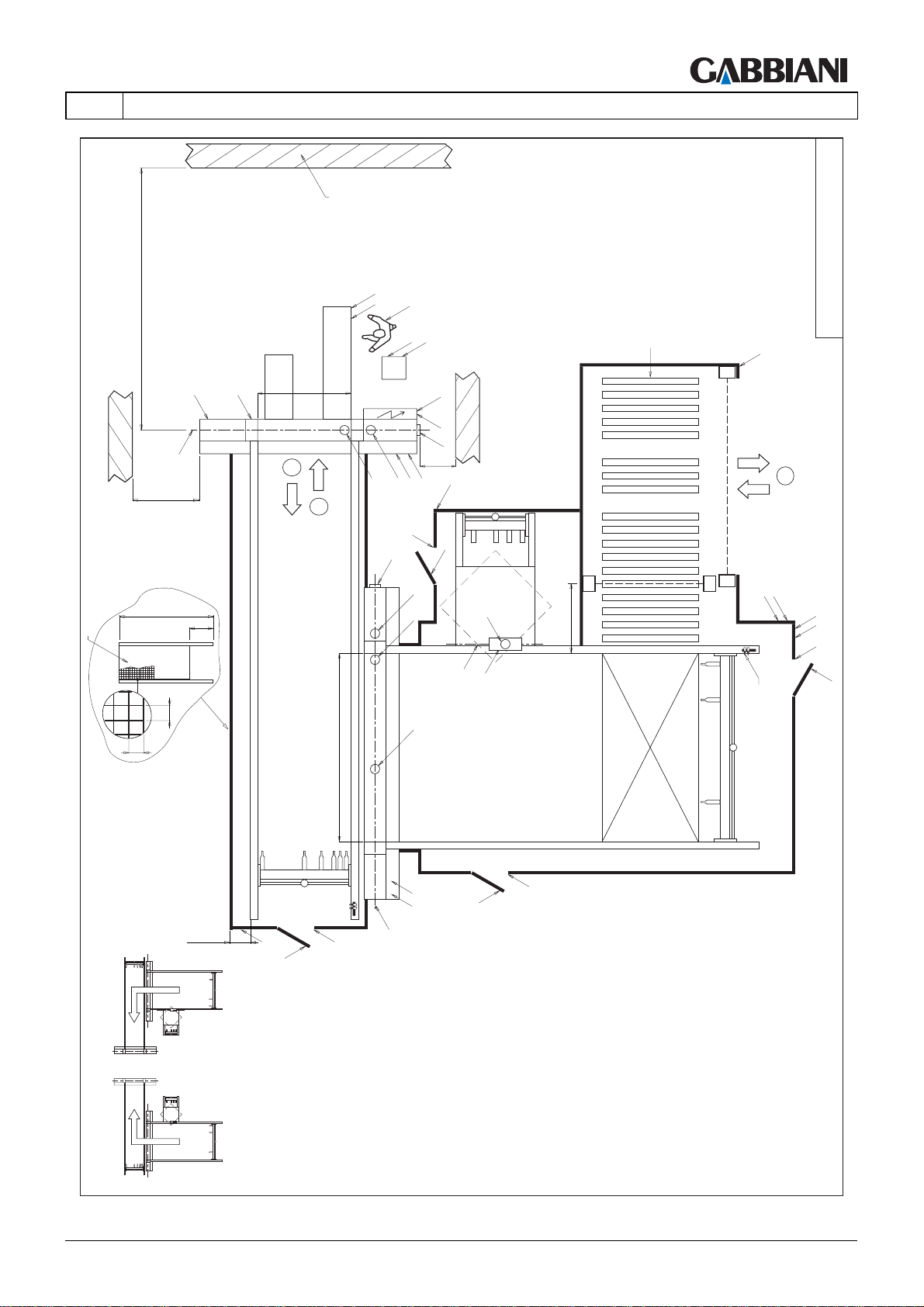
CONFIGURATION AND OPERATOR POSITION, OVERALL DIMENSIONS AND SAFETY DISTANCES
The following figures illustrate:
- possible machine loading and unloading configurations:
1) fontal manual unloading;
2) frontal manual loading;
3) rear automatic unloading;
4) lateral automatic loading;
- suction connecting points: A(Ø=120 mm), A1(Ø=100 mm), B(Ø=150 mm);
- padlockable pneumatic on-off valves (IP) and pneumatic connecting points (IP1);
- main padlockable electrical switches (IE) and electrical connecting points (IE1);
- control panel (F);
- transversal saw cutting axe (G);
- longitudinal saw cutting axe (G1);
- precut unit cutting axe (G2);
- manually opened doors (H): allow access inside the panel saw perimeter fence for maintenance; fitted with an
interlocking device with guard locking (mechanical safety limit switch "H1" with reset knob);
- manually opened doors (H2): allow access inside the panel saw perimeter fence for manual removal of the trim
cut collection container (CR); fitted with an interlocking device with guard locking (mechanical safety limit switch
"H1" with reset knob) and a RESET button (RH2);
- unloading device automatically opened doors (I1): open to allow automatic unloading; fitted with an interlocking
device without guard locking (mechanical safety limit switch "I2");
- safety photocells with manual reset (I3) for the unloading device automatically opened door (I1); photocell
interruption when the door (I1) is open triggers a machine emergency state;
- unstable selectors (RI3) to RESET safety photocells (I3)
- emergency stop devices (L);
- manually opened doors (L1) of the unloading device;
- manually opened door safety limit switches (L2);
- RESET buttons(RL1) for resetting manually opened doors (L1);
- manually opened doors (L1a): allow access inside the panel saw perimeter fence for maintenance; fitted with an
interlocking device with guard locking (mechanical safety limit switch "L2a" with reset knob);
- pushbutton panel for blade replacement (M);
- pusher calibration check limit switch (MT);
- pushbutton panel for precutting unit blade replacement (N)
- pushbutton panel to stop the pusher (O);
- photoelectric safety barriers (X, Y) with 2 beams (able to detect a breach by the whole body or parts of it) for
protecting the panel saw loading zone;
- unstable selectors (P) for RESETTING the photoelectric barriers (X, Y); must be more than 850 mm from the
barrier to prevent the operator from performing the RESET from inside the protected area;
- photoelectric safety barriers (X1) with 64 beams (with 30 mm detection capacity, able to detect a breach by the
hands), for protecting the panel saw loading zone;
- unstable selectors (P1) for RESETTING the photoelectric barriers (X1); must be more than 850 mm from the
barrier to prevent the operator from performing the RESET from inside the protected area;
- photoelectric safety barriers (X2, Y2) of the unloading device, for protecting the panel saw loading zone
- unstable selectors (P2) for RESETTING the photoelectric barriers (X2, Y2); must be more than 850 mm from the
barrier to prevent the operator from performing the RESET from inside the protected area;
- panel saw photoelectric safety barriers, for protecting the front unloading zone (BF, BF1)
- motor-driven roller conveyors (R): the rollers may be motor-driven automatically or manually (maintained action)
using unstable selectors (R1, R2, R3, etc.);
- safety distance (S) from the cutting axis to the wall or fixed obstacle; it must be observed to avoid the danger of
the operator being crushed if whole panels come out of the machine.
Install the saw observing the safety distance "S".
After installation do not create obstacles in the area within the safety distance. Never place objects (for example
stacks of panels) less than the safety distance "S" from the cutting axis.
IT MUST ALWAYS BE: S > PR + 500 mm ;
- (T) positive safety cam
- (T1) safety area: during panel loading on the elevator table if the safety photocells (X) are interrupted the pusher
can continue moving, but only within the area "T1". A safety limit switch on the pusher, positively activated by the
cam "T", indicates its position.
4 - TRANSPORT AND INSTALLATION
THIS MANUAL IS PROPERTY OF - SCM GROUP SPA. - ANY TOTAL OR PARTIAL REPRODUCTION IS STRICTLY FORBIDDEN Cap. 4 - Pag. 3/79
Page 46

105-125
4 - TRANSPORT AND INSTALLATION
- (BA) safety device: Prevents the risk of impact between panels coming out of the panel saw, pushed by the
pusher, and the protective fences of the automatic unloading device. If the panels press on this slat device it
activates a safety limit switch which stops the pusher.
- (CH) closing plate
- (DS) safety device (sensitive edge): pressure-sensitive device; prevents the risk of hands getting crushed
between panels coming out of the panel saw, pushed by the pusher, and the opening in the automatic unloading
device protective fences. Pressing on this device stops the pusher.
- trim cut management hatch (U);
- trim cut rotary containment and unloading case (V);
- vibrating conveyor belt (V1);
- trim cut cutter (V2);
- tilting conveyor belt (V3);
- wall or obstacle (W), if present;
- operator position (OP);
- safety fences (RP);
EN
Cap. 4 - Pag. 4/79 THIS MANUAL IS PROPERTY OF - SCM GROUP SPA. - ANY TOTAL OR PARTIAL REPRODUCTION IS STRICTLY FORBIDDEN
Page 47
105-125
4 - TRANSPORT AND INSTALLATION
LAYOUT_FLEXIMA_001
EN
S (>PR+500)
W
L
O
OP
L
F
L
M
G
>1600
2000
RP
40
300
40
LT
2
A
1
B
IE1
IE
B
>500
A
L
IP
IP1
H
A
A
A1
H1
y
E
G2
1000
A
PR
T1
T
150
L
P1
L
N
x1
MT
850
L
P
L
N
x
MT
3
x
LEFT CONFIGURATION
RIGHT CONFIGURATION
min.200
y
M
L
L
H
H1
G1
H
H1
THIS MANUAL IS PROPERTY OF - SCM GROUP SPA. - ANY TOTAL OR PARTIAL REPRODUCTION IS STRICTLY FORBIDDEN Cap. 4 - Pag. 5/79
L
Page 48
105-125
4 - TRANSPORT AND INSTALLATION
W
S (>PR+500)
EN
L
O
OP
L
F
LAYOUT_FLEXIMA_002
L
M
G
>1600
2000
RP
40
300
40
LT
2
A
IE1
IE
B
>500
A
IP
IP1
P1
1
B
A
A
A
PR
T1
T
150
L
x1
MT
850
LMTP
x
3
x
L
M
L
G1
LEFT CONFIGURATION
RIGHT CONFIGURATION
200
min. 200
L
H
H1
Cap. 4 - Pag. 6/79 THIS MANUAL IS PROPERTY OF - SCM GROUP SPA. - ANY TOTAL OR PARTIAL REPRODUCTION IS STRICTLY FORBIDDEN
Page 49
105-125
4 - TRANSPORT AND INSTALLATION
LAYOUT_FLEXIMA_003
EN
S (>PR+500)
G
>1600
W
L
O
OP
L
F
L
M
LT
2
A
IE1
IE
B
>500
A
L
IP
IP1
1
B
A
2000
RP
40
300
40
PR
200
min. 200
L
H
H1
A
A
M
L
G1
A1
E
G2
H
H1
1000
H
H1
MT
P
y
y
L
x
L
N
H1
H
LEFT CONFIGURATION
4
R
L
x
RIGHT CONFIGURATION
THIS MANUAL IS PROPERTY OF - SCM GROUP SPA. - ANY TOTAL OR PARTIAL REPRODUCTION IS STRICTLY FORBIDDEN Cap. 4 - Pag. 7/79
Page 50
105-125
4 - TRANSPORT AND INSTALLATION
W
S (>PR+500)
L
M
G
>1600
LT
2
1
EN
L
O
OP
L
F
IE1
IE
B
>500
A
A
L
IP
IP1
LAYOUT_FLEXIMA_004
B
A
2000
RP
40
300
40
PR
min .200
L
H
H1
A
A
M
L
G1
A1
E
G2
P
H
L
H1
H
H1
MT
1000
y
x
y
L
N
H1
H
4
LEFT CONFIGURATION
R
L
x
RIGHT CONFIGURATION
Cap. 4 - Pag. 8/79 THIS MANUAL IS PROPERTY OF - SCM GROUP SPA. - ANY TOTAL OR PARTIAL REPRODUCTION IS STRICTLY FORBIDDEN
Page 51
105-125
4 - TRANSPORT AND INSTALLATION
LAYOUT_FLEXIMA_005
EN
S (>PR+500)
G
>1600
W
L
O
OP
L
F
L
M
LT
2
A
IE1
IE
B
>500
A
L
IP
IP1
1
B
A
2000
RP
40
300
40
PR
A
A
A1
E
G2
T1
T
1000
H
H1
L
N
y
H1
H
MT
y
200
200min. 200
M
L
L
H
H1
G1
H
1000
H1
x
L
x
P
L
LEFT CONFIGURATION
4
4
4
R
RIGHT CONFIGURATION
THIS MANUAL IS PROPERTY OF - SCM GROUP SPA. - ANY TOTAL OR PARTIAL REPRODUCTION IS STRICTLY FORBIDDEN Cap. 4 - Pag. 9/79
Page 52
105-125
4 - TRANSPORT AND INSTALLATION
W
S (>PR+500)
L
M
G
>1600
LT
2
1
EN
L
O
OP
L
F
IE1
IE
B
>500
A
A
IP
IP1
LAYOUT_FLEXIMA_006
B
A
2000
RP
40
300
40
PR
200
200min. 200
L
H
H1
A
MT
A
T1
T
M
1000
L
G1
x
L
x
P
L
L
N
H1
H
LEFT CONFIGURATION
4
4
4
R
RIGHT CONFIGURATION
Cap. 4 - Pag. 10/79 THIS MANUAL IS PROPERTY OF - SCM GROUP SPA. - ANY TOTAL OR PARTIAL REPRODUCTION IS STRICTLY FORBIDDEN
Page 53
105-125
4 - TRANSPORT AND INSTALLATION
LAYOUT_FLEXIMA_007
R
L
x
4
EN
S (>PR+500)
G
>1600
W
L
O
OP
L
F
L
M
LT
2
A
IE1
IE
B
>500
A
L
IP
IP1
1
H1
B
2000
RP
40
300
40
PR
200200min. 200
L
H
H1
G1
H
x
A
A
A
M
L
A1
E
G2
H
H1
y
1000
y
P
L
L
N
H1
MT
H
LEFT CONFIGURATION
RIGHT CONFIGURATION
THIS MANUAL IS PROPERTY OF - SCM GROUP SPA. - ANY TOTAL OR PARTIAL REPRODUCTION IS STRICTLY FORBIDDEN Cap. 4 - Pag. 11/79
Page 54
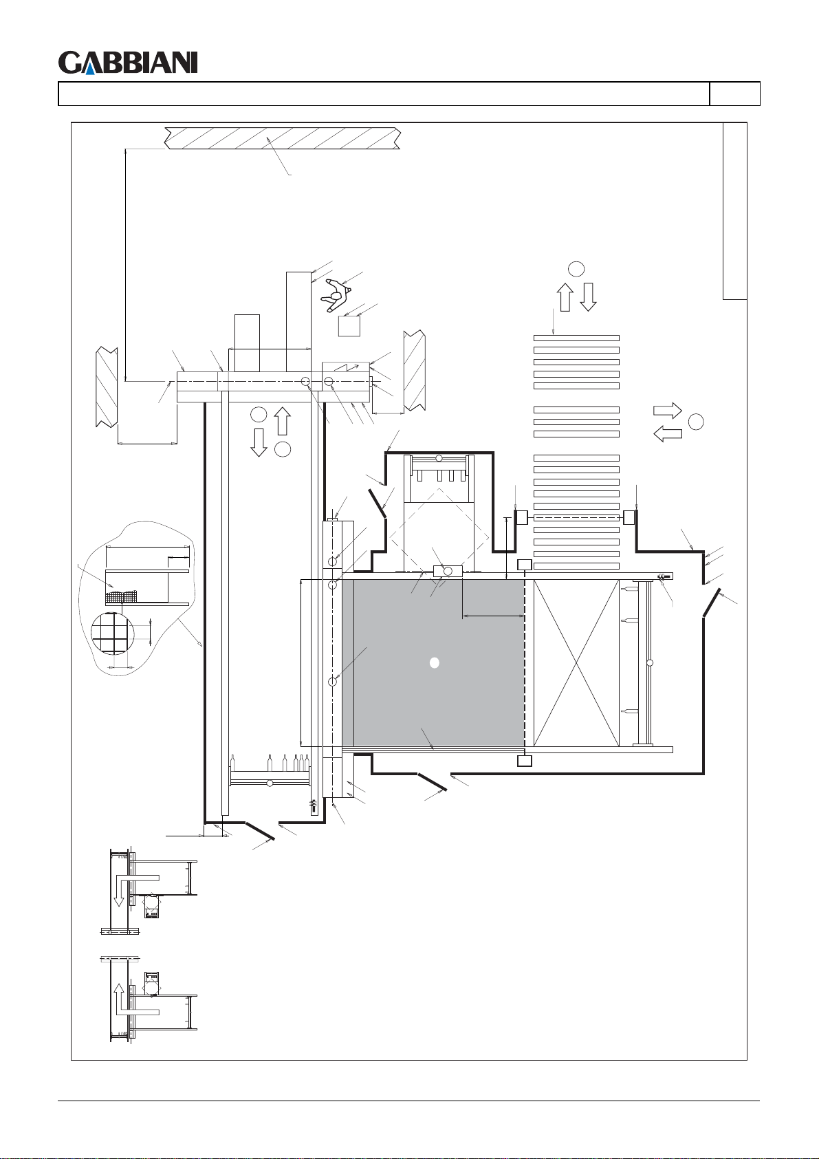
105-125
4 - TRANSPORT AND INSTALLATION
W
S (>PR+500)
L
M
G
>1600
LT
2
1
EN
L
O
OP
L
F
IE1
IE
B
>500
A
A
L
IP
IP1
4
R
LAYOUT_FLEXIMA_008
4
H1
B
2000
RP
40
300
40
PR
H
A
A
A
A1
E
G2
T1
T
L
x
1000
y
1000
L
x
P
L
N
H1
H
MT
y
H1
200200min. 200
M
L
L
H
H1
G1
H
LEFT CONFIGURATION
RIGHT CONFIGURATION
Cap. 4 - Pag. 12/79 THIS MANUAL IS PROPERTY OF - SCM GROUP SPA. - ANY TOTAL OR PARTIAL REPRODUCTION IS STRICTLY FORBIDDEN
Page 55
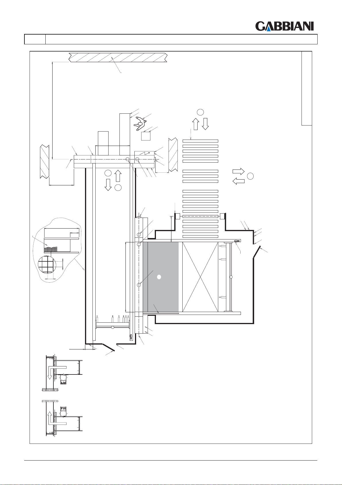
105-125
4 - TRANSPORT AND INSTALLATION
4
R
4
LAYOUT_FLEXIMA_009
EN
S (>PR+500)
G
>1600
W
L
O
OP
L
F
L
M
LT
2
A
IE1
IE
B
>500
A
IP
IP1
1
B
A
2000
RP
40
300
40
PR
200200min. 200
L
H
H1
A
A
T
M
L
G1
L
x
1000
T1
x
P
L
L
N
H1
H
MT
LEFT CONFIGURATION
RIGHT CONFIGURATION
THIS MANUAL IS PROPERTY OF - SCM GROUP SPA. - ANY TOTAL OR PARTIAL REPRODUCTION IS STRICTLY FORBIDDEN Cap. 4 - Pag. 13/79
Page 56
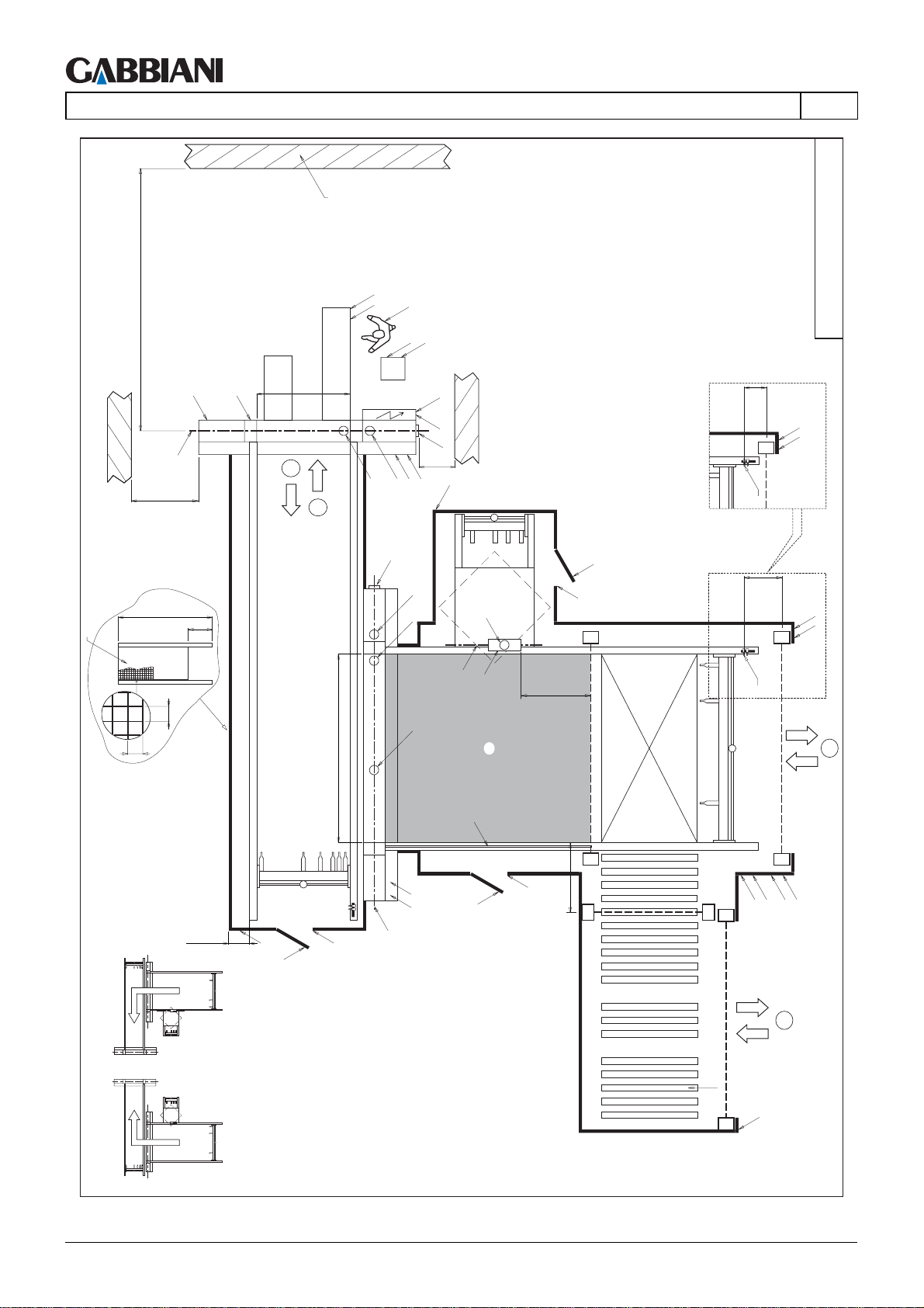
105-125
4 - TRANSPORT AND INSTALLATION
W
S (>PR+500)
EN
L
O
OP
L
F
LAYOUT_FLEXIMA_010
L
M
G
>1600
2000
RP
40
300
40
LT
2
A
IE1
IE
B
>500
A
L
IP
IP1
1
B
A
A
A
PR
A1
E
G2
T1
T
H
H1
y
1000
150
L
N
x1
MT
850
L
N
x
MT
3
LEFT CONFIGURATION
RIGHT CONFIGURATION
200200min. 200
y
M
L
L
H
H1
G1
H
H1
1000
y
y
x
R
x
LPL
L
x
P/P1
4
Cap. 4 - Pag. 14/79 THIS MANUAL IS PROPERTY OF - SCM GROUP SPA. - ANY TOTAL OR PARTIAL REPRODUCTION IS STRICTLY FORBIDDEN
Page 57
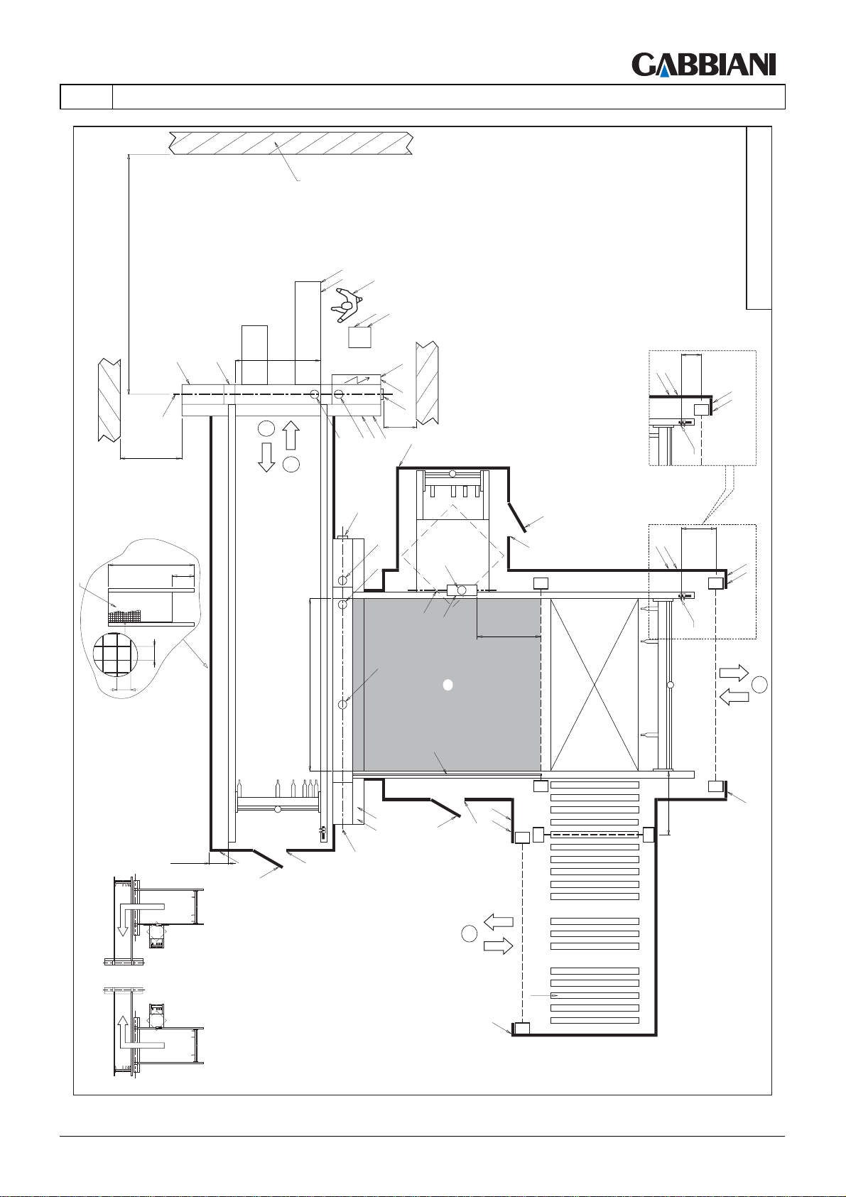
105-125
4 - TRANSPORT AND INSTALLATION
LAYOUT_FLEXIMA_011
EN
S (>PR+500)
W
L
O
OP
L
F
L
M
G
>1600
2000
RP
40
300
40
LT
2
A
IE1
IE
B
>500
A
L
IP
IP1
1
B
A
A
A
PR
A1
E
G2
T1
T
H
H1
y
1000
150
L
P1
L
N
x1
MT
850
L
P
L
N
x
MT
MT
3
LEFT CONFIGURATION
RIGHT CONFIGURATION
200200min. 200
y
M
L
L
H
H1
G1
H
L P
H1
y
x
1000
y
4
R
L
x
x
THIS MANUAL IS PROPERTY OF - SCM GROUP SPA. - ANY TOTAL OR PARTIAL REPRODUCTION IS STRICTLY FORBIDDEN Cap. 4 - Pag. 15/79
L
Page 58
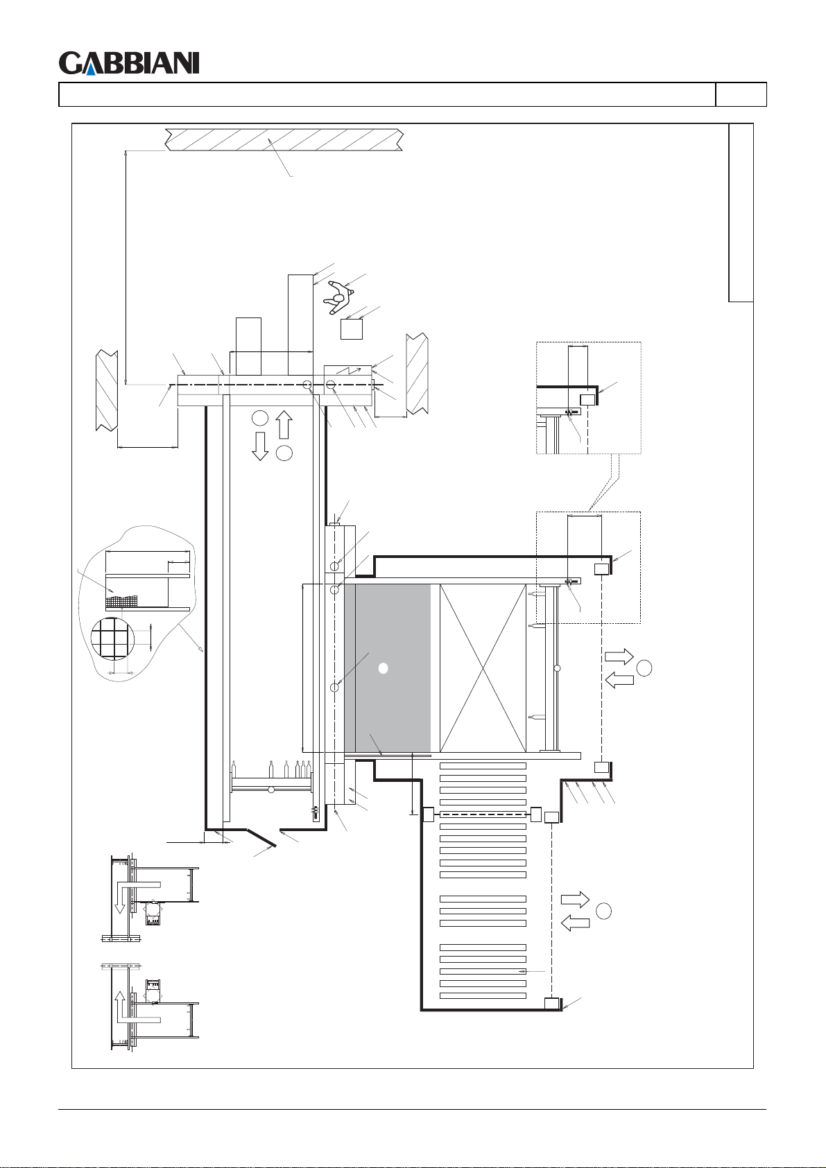
105-125
4 - TRANSPORT AND INSTALLATION
W
S (>PR+500)
EN
L
O
OP
L
F
LAYOUT_FLEXIMA_012
L
M
G
>1600
2000
RP
40
300
40
LT
2
A
IE1
IE
B
>500
A
IP
IP1
1
B
A
A
A
PR
T1
T
150
L
x1
MT
850
L
x
MT
3
x
M
LEFT CONFIGURATION
RIGHT CONFIGURATION
200200min. 200
1000
L
L
H
H1
G1
y
y
LPL
x
P/P1
4
R
L
x
Cap. 4 - Pag. 16/79 THIS MANUAL IS PROPERTY OF - SCM GROUP SPA. - ANY TOTAL OR PARTIAL REPRODUCTION IS STRICTLY FORBIDDEN
Page 59
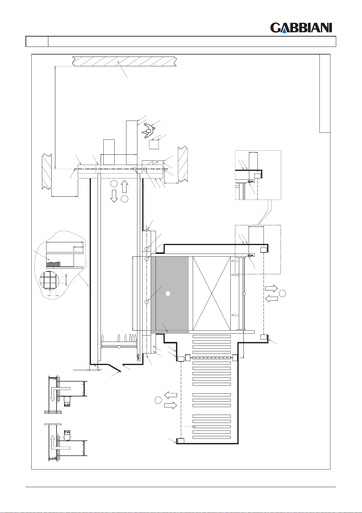
105-125
4 - TRANSPORT AND INSTALLATION
LAYOUT_FLEXIMA_013
EN
S (>PR+500)
W
L
O
OP
L
F
L
M
G
>1600
2000
RP
40
300
40
LT
2
A
IE1
IE
B
>500
A
IP
IP1
P1
1
B
A
A
A
PR
T1
T
P
150
L
x1
MT
850
L
x
MT
3
x
L
L P
M
L
200200min. 200
LEFT CONFIGURATION
RIGHT CONFIGURATION
THIS MANUAL IS PROPERTY OF - SCM GROUP SPA. - ANY TOTAL OR PARTIAL REPRODUCTION IS STRICTLY FORBIDDEN Cap. 4 - Pag. 17/79
L
H
H1
G1
4
L
y
x
R
x
1000
y
Page 60
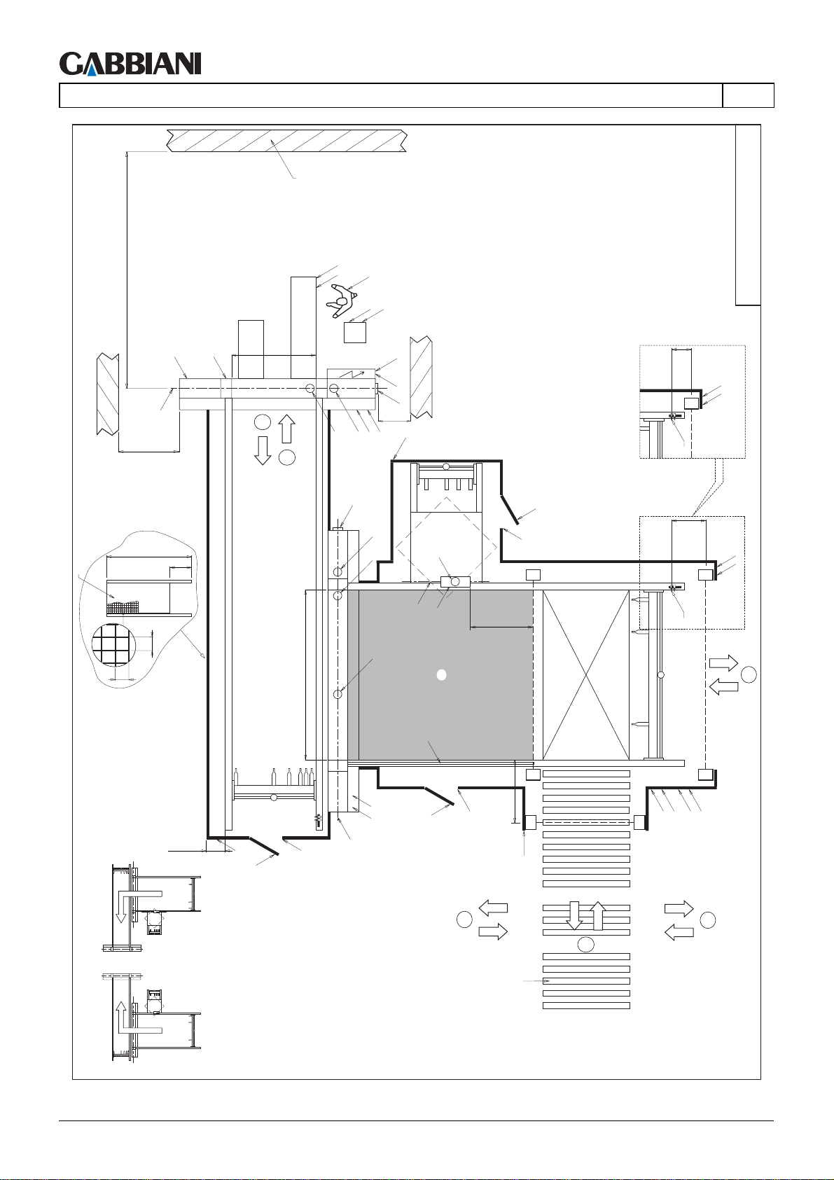
105-125
4 - TRANSPORT AND INSTALLATION
W
S (>PR+500)
EN
L
O
OP
L
F
LAYOUT_FLEXIMA_014
L
M
G
>1600
2000
RP
40
300
40
LT
2
A
IE1
IE
B
>500
A
L
IP
IP1
1
B
A
A
A
PR
A1
E
G2
T1
T
I
H1
y
1000
150
L
N
x1
MT
850
L
N
x
MT
3
LEFT CONFIGURATION
200200min. 200
y
M
L
L
H
H1
G1
H
1000
H1
x
L
x
4
LPL
P/P1
x
4
4
R
RIGHT CONFIGURATION
Cap. 4 - Pag. 18/79 THIS MANUAL IS PROPERTY OF - SCM GROUP SPA. - ANY TOTAL OR PARTIAL REPRODUCTION IS STRICTLY FORBIDDEN
Page 61
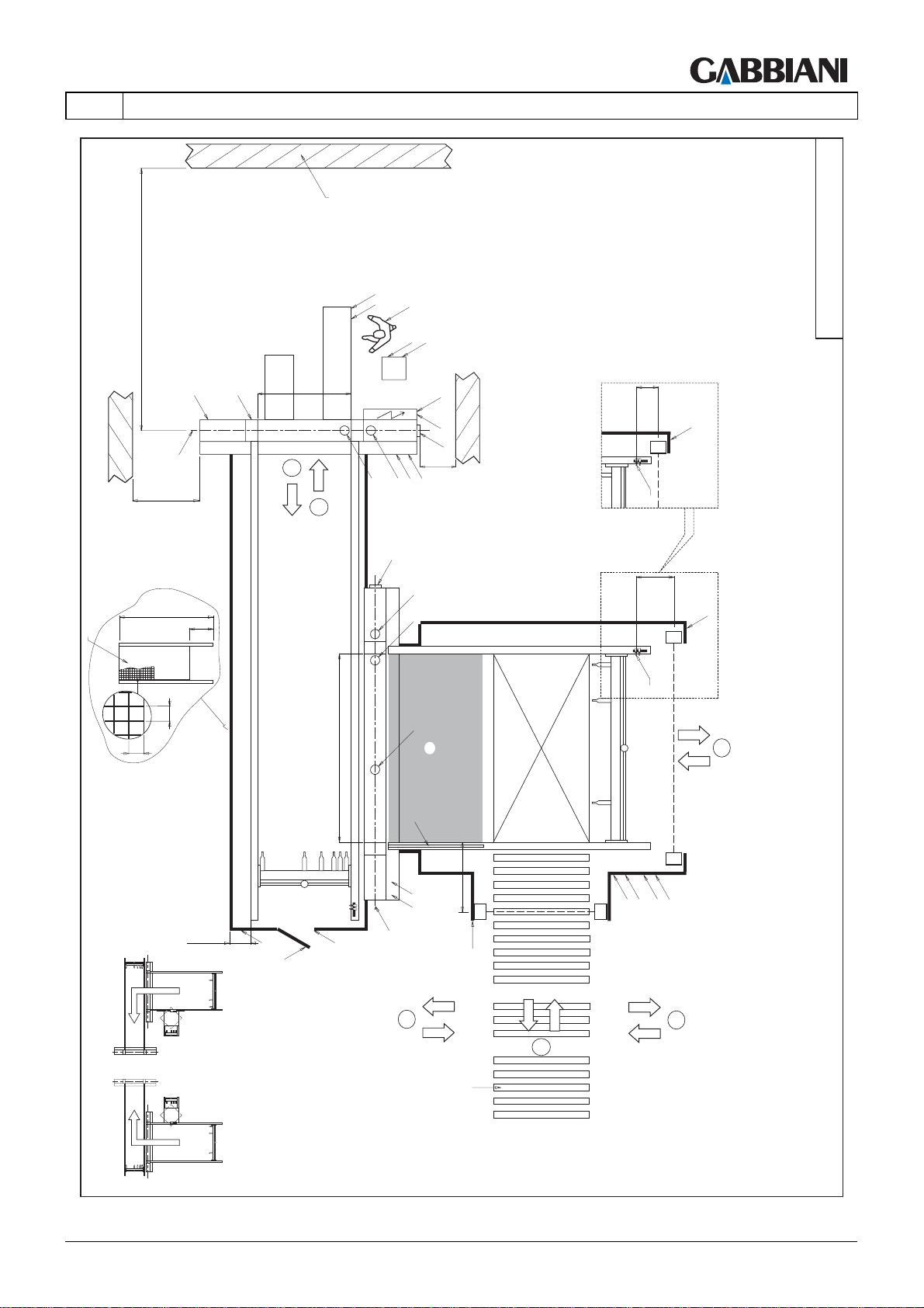
105-125
4 - TRANSPORT AND INSTALLATION
LAYOUT_FLEXIMA_015
EN
S (>PR+500)
W
L
O
OP
L
F
L
M
G
>1600
2000
RP
40
300
40
LT
2
A
IE1
IE
B
>500
A
IP
IP1
1
B
A
A
A
PR
T1
T
150
L
x1
MT
850
L
x
MT
3
x
M
LEFT CONFIGURATION
200200min. 200
1000
L
L
H
H1
G1
x
L
4
LPL
x
P/P1
4
4
R
RIGHT CONFIGURATION
THIS MANUAL IS PROPERTY OF - SCM GROUP SPA. - ANY TOTAL OR PARTIAL REPRODUCTION IS STRICTLY FORBIDDEN Cap. 4 - Pag. 19/79
Page 62
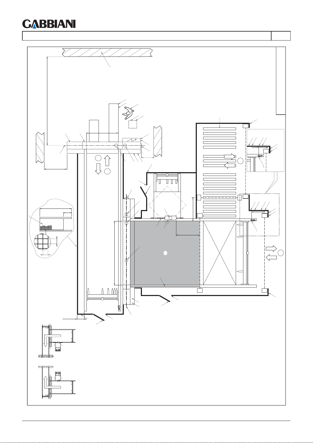
105-125
4 - TRANSPORT AND INSTALLATION
W
S (>PR+500)
L
M
G
>1600
LT
2
1
EN
L
O
OP
L
F
R
L
x
IE1
IE
B
>500
A
A
L
IP
IP1
4
LPL
150
P1
MT
LAYOUT_FLEXIMA_016
L
N
x1
H1
H
B
2000
RP
40
300
40
PR
min. 200
L
H
H1
G1
I
x
A
A
A1
y
1000
y
E
G2
1000
A
T1
T
y
M
L
H
H1
y
LPL
850
MT
P
L
N
x
3
x
L
LEFT CONFIGURATION
RIGHT CONFIGURATION
Cap. 4 - Pag. 20/79 THIS MANUAL IS PROPERTY OF - SCM GROUP SPA. - ANY TOTAL OR PARTIAL REPRODUCTION IS STRICTLY FORBIDDEN
Page 63
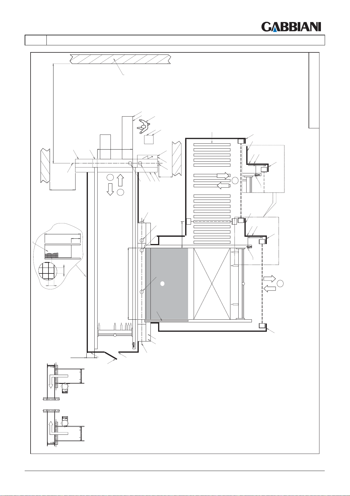
105-125
4 - TRANSPORT AND INSTALLATION
LAYOUT_FLEXIMA_017
R
4
L
L
x
P1
P
150
L
x1
MT
EN
S (>PR+500)
G
>1600
W
L
O
OP
L
F
L
M
LT
2
A
IE1
IE
B
>500
A
IP
IP1
1
B
A
2000
RP
40
300
40
PR
A
A
T1
T
y
1000
y
L
x
P
P
850
MT
L
x
3
x
L
M
L
min. 200
L
H
H1
G1
LEFT CONFIGURATION
RIGHT CONFIGURATION
THIS MANUAL IS PROPERTY OF - SCM GROUP SPA. - ANY TOTAL OR PARTIAL REPRODUCTION IS STRICTLY FORBIDDEN Cap. 4 - Pag. 21/79
Page 64
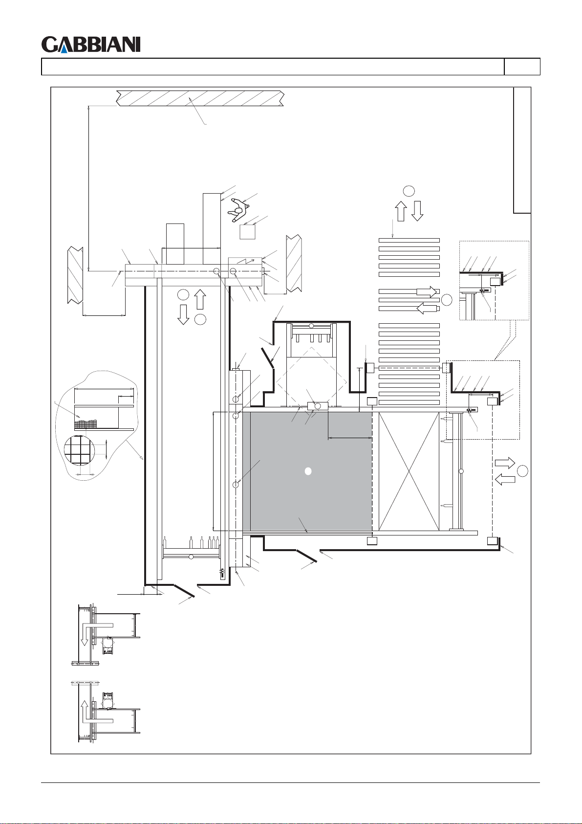
105-125
4 - TRANSPORT AND INSTALLATION
W
S (>PR+500)
L
M
G
>1600
LT
2
1
EN
L
O
OP
L
F
IE1
IE
B
>500
A
A
L
IP
IP1
4
R
LPL
P1
150
LAYOUT_FLEXIMA_018
L
N
x1
4
MT
H1
I
B
2000
RP
40
300
40
PR
min. 200
L
H
H1
G1
H
A
A
A
M
L
A1
E
G2
T1
T
H
H1
1000
1000
L
y
y
y
LPL
P
L
850
MT
N
x
3
y
x
L
LEFT CONFIGURATION
RIGHT CONFIGURATION
Cap. 4 - Pag. 22/79 THIS MANUAL IS PROPERTY OF - SCM GROUP SPA. - ANY TOTAL OR PARTIAL REPRODUCTION IS STRICTLY FORBIDDEN
Page 65
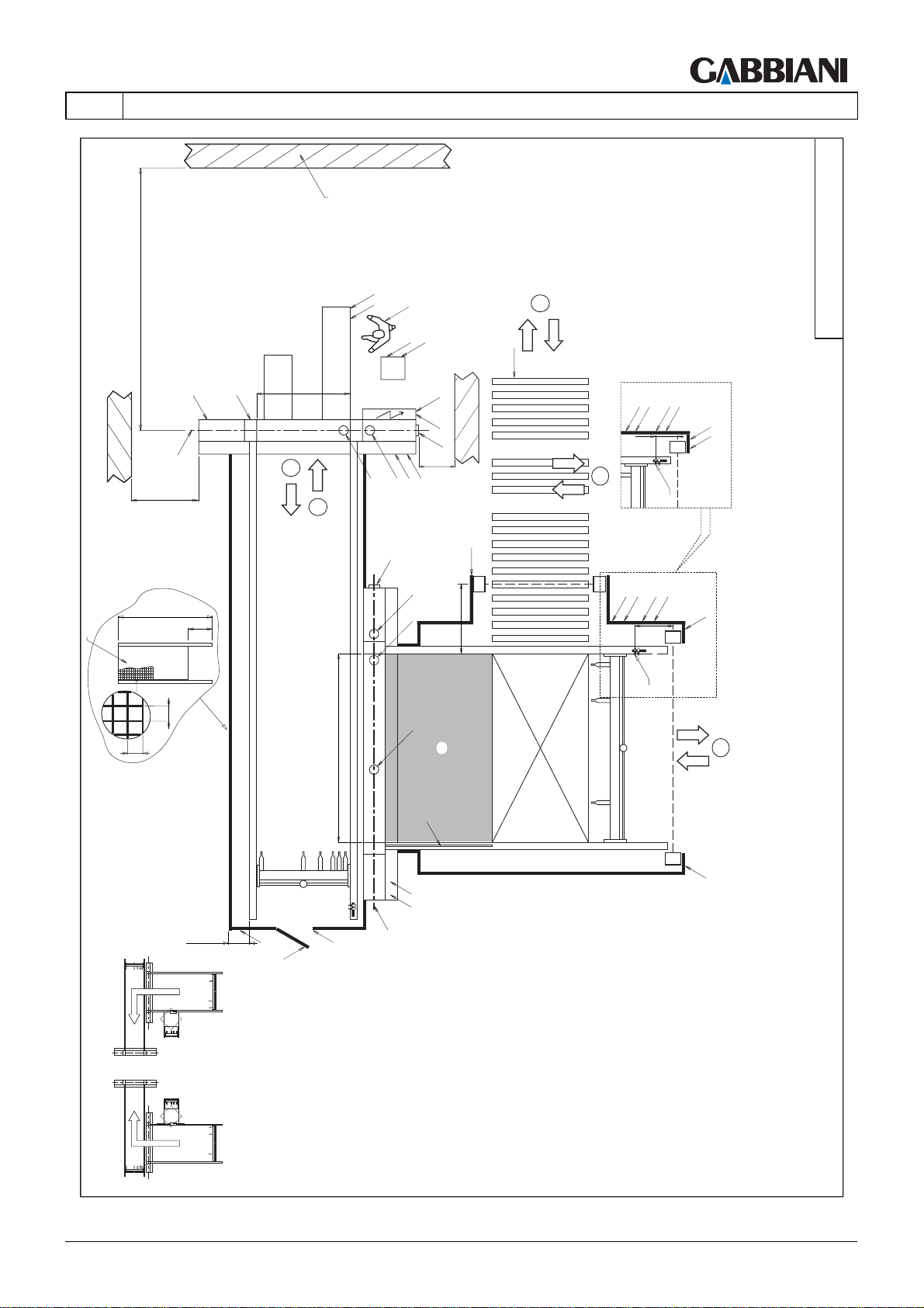
105-125
4 - TRANSPORT AND INSTALLATION
4
R
LPL
P1
L
150
4
N
x1
MT
LAYOUT_FLEXIMA_019
EN
S (>PR+500)
G
>1600
W
L
O
OP
L
F
L
M
LT
2
A
IE1
IE
B
>500
A
IP
IP1
1
B
A
2000
RP
40
300
40
PR
A
A
T
L
x
1000
T1
x
LPL
P
850
MT
L
x
3
x
L
M
L
min. 200
L
H
H1
G1
LEFT CONFIGURATION
RIGHT CONFIGURATION
THIS MANUAL IS PROPERTY OF - SCM GROUP SPA. - ANY TOTAL OR PARTIAL REPRODUCTION IS STRICTLY FORBIDDEN Cap. 4 - Pag. 23/79
Page 66
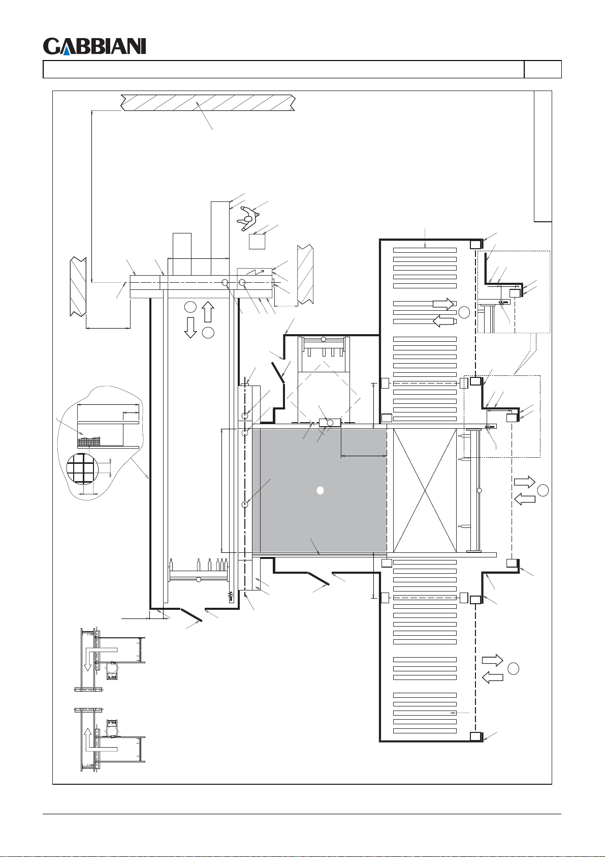
105-125
4 - TRANSPORT AND INSTALLATION
W
S (>PR+500)
L
M
G
>1600
LT
2
1
EN
L
O
OP
L
F
IE1
IE
B
>500
A
A
L
IP
IP1
R
LL
L
x
P1
P
150
4
MT
LAYOUT_FLEXIMA_020
L
N
x1
H1
I
B
2000
RP
40
300
40
PR
min. 200
L
H
H1
G1
H
A
A
A1
y
1000
y
y
E
G2
1000
A
T1
T
y
y
M
L
H
H1
1000
y
y
L
x
P
P
L
850
MT
N
x
3
x
L
P
x
L
LEFT CONFIGURATION
4
R
x
RIGHT CONFIGURATION
Cap. 4 - Pag. 24/79 THIS MANUAL IS PROPERTY OF - SCM GROUP SPA. - ANY TOTAL OR PARTIAL REPRODUCTION IS STRICTLY FORBIDDEN
Page 67
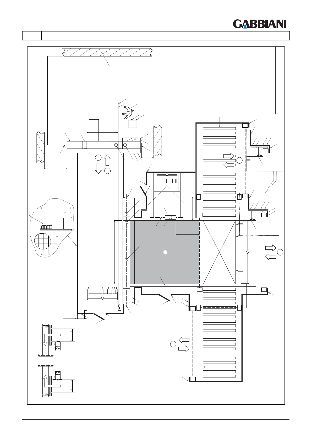
105-125
4 - TRANSPORT AND INSTALLATION
LAYOUT_FLEXIMA_021
R
4
L
L
x
LPL
P1
150
L
x1
MT
EN
S (>PR+500)
G
>1600
W
L
O
OP
L
F
L
M
LT
2
A
IE1
IE
B
>500
A
L
IP
IP1
1
H1
I
B
2000
RP
40
300
40
PR
min. 200
L
H
H1
G1
H
A
A
A1
y
1000
y
E
G2
1000
A
T1
T
y
y
M
L
H
L P
H1
y
x
L
x
y
850
MT
LPL
P
x
L
N
3
x
L
1000
y
LEFT CONFIGURATION
4
R
L
x
RIGHT CONFIGURATION
THIS MANUAL IS PROPERTY OF - SCM GROUP SPA. - ANY TOTAL OR PARTIAL REPRODUCTION IS STRICTLY FORBIDDEN Cap. 4 - Pag. 25/79
Page 68
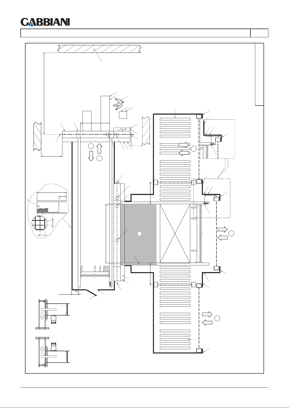
105-125
4 - TRANSPORT AND INSTALLATION
W
S (>PR+500)
L
M
G
>1600
LT
2
1
EN
L
O
OP
L
F
IE1
IE
B
>500
A
A
IP
IP1
R
LL
L
x
P
P1
150
L
x1
4
MT
LAYOUT_FLEXIMA_022
B
A
2000
RP
40
300
40
PR
A
A
T1
T
y
1000
y
L
x
P
P
850
MT
L
x
3
x
L
M
L
min. 200
L
H
H1
G1
1000
y
y
P
x
L
LEFT CONFIGURATION
4
R
x
RIGHT CONFIGURATION
Cap. 4 - Pag. 26/79 THIS MANUAL IS PROPERTY OF - SCM GROUP SPA. - ANY TOTAL OR PARTIAL REPRODUCTION IS STRICTLY FORBIDDEN
Page 69
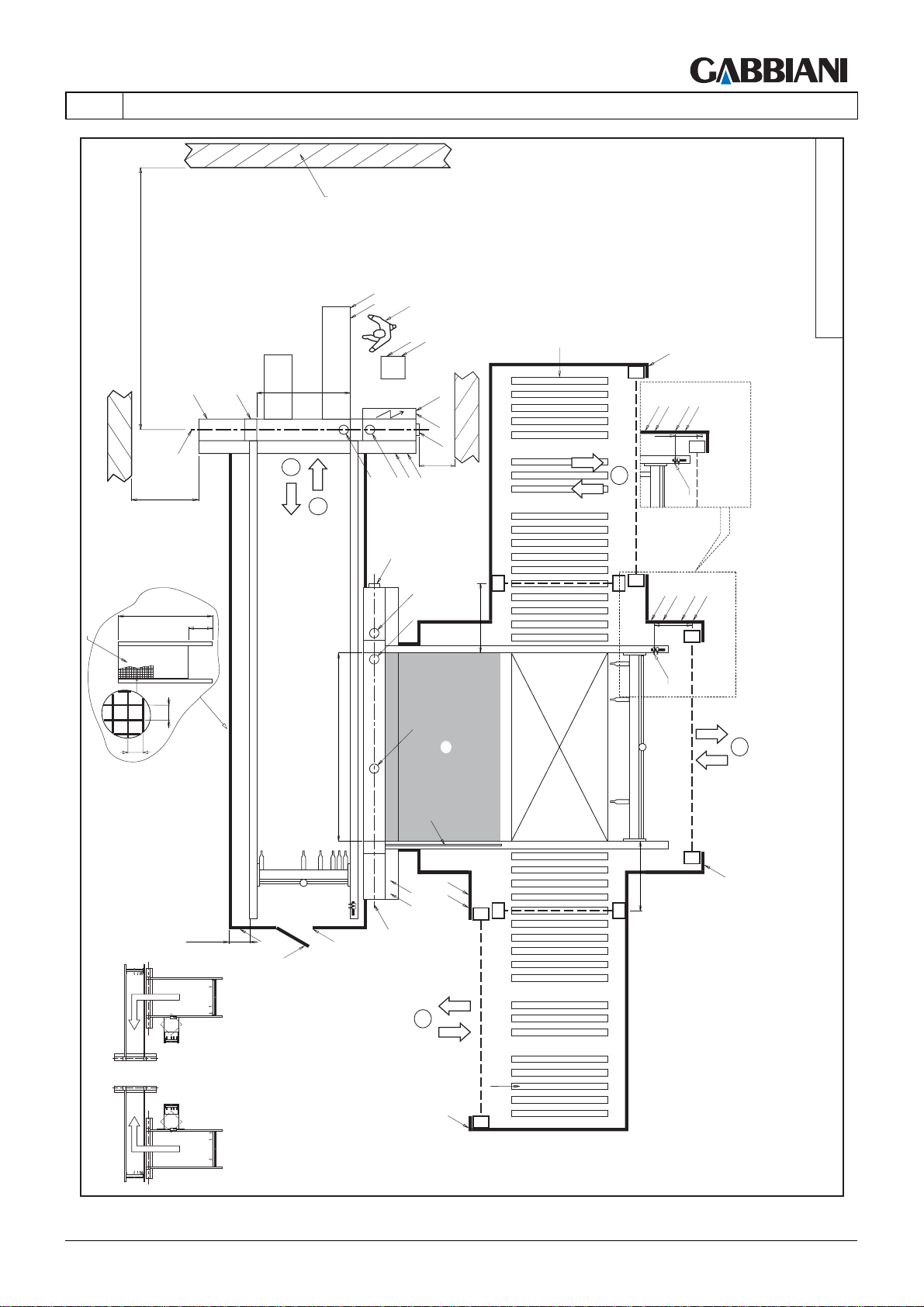
105-125
4 - TRANSPORT AND INSTALLATION
LAYOUT_FLEXIMA_023
R
L
x
LPL
P1
EN
S (>PR+500)
W
L
O
OP
L
F
L
M
LT
IE1
IE
G
>1600
2000
RP
40
300
40
2
A
A
1
B
PR
B
>500
IP
IP1
A
A
A
T1
T
y
1000
y
150
x1
4
MT
x
LPL
P
850
x
MT
3
x
L P
M
L
min. 200
L
H
H1
G1
y
x
1000
y
L
4
LEFT CONFIGURATION
R
L
x
RIGHT CONFIGURATION
THIS MANUAL IS PROPERTY OF - SCM GROUP SPA. - ANY TOTAL OR PARTIAL REPRODUCTION IS STRICTLY FORBIDDEN Cap. 4 - Pag. 27/79
Page 70
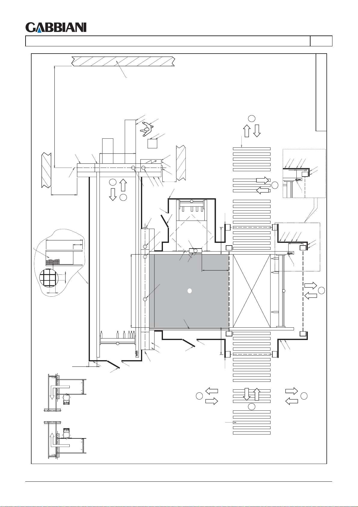
105-125
4 - TRANSPORT AND INSTALLATION
W
S (>PR+500)
L
M
G
>1600
LT
2
1
EN
L
O
OP
L
F
IE1
IE
B
>500
A
A
L
IP
IP1
4
R
LPL
P1
150
4
MT
LAYOUT_FLEXIMA_024
L
N
x1
H1
I
B
2000
RP
40
300
40
PR
min. 200
L
H
H1
G1
H
A
A
A
M
L
A1
E
G2
T1
T
H
H1
1000
1000
1000
L
x
y
x
LPL
P
L
850
MT
N
x
3
y
y
x
L
x
x
L
P
4
LEFT CONFIGURATION
RIGHT CONFIGURATION
4
4
R
Cap. 4 - Pag. 28/79 THIS MANUAL IS PROPERTY OF - SCM GROUP SPA. - ANY TOTAL OR PARTIAL REPRODUCTION IS STRICTLY FORBIDDEN
Page 71
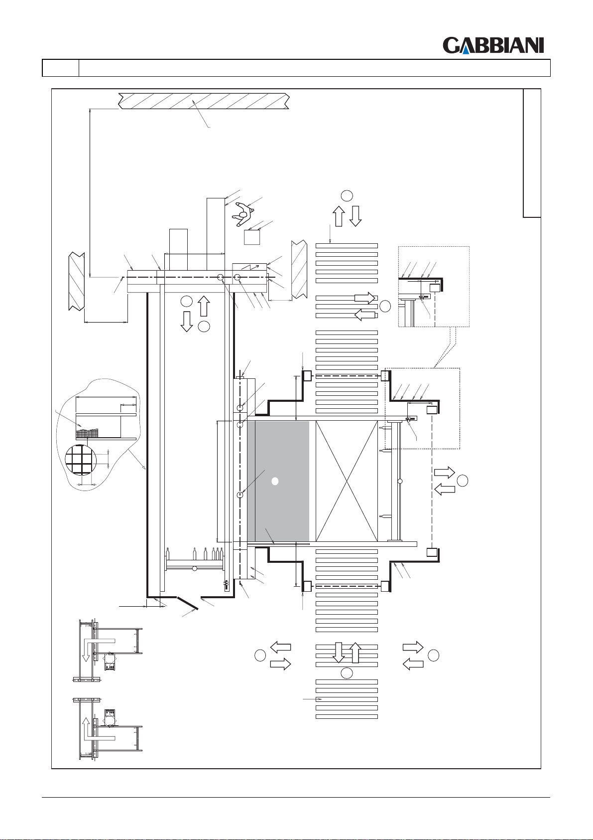
105-125
4 - TRANSPORT AND INSTALLATION
4
R
LPL
P1
150
x1
4
MT
LAYOUT_FLEXIMA_025
EN
S (>PR+500)
G
>1600
W
L
O
OP
L
F
L
M
LT
2
A
IE1
IE
B
>500
A
IP
IP1
1
B
A
2000
RP
40
300
40
PR
A
A
T
L
x
1000
T1
x
LPL
P
850
x
MT
3
x
M
1000
L
min. 200
L
H
H1
G1
x
L
L
P
x
4
LEFT CONFIGURATION
R
RIGHT CONFIGURATION
THIS MANUAL IS PROPERTY OF - SCM GROUP SPA. - ANY TOTAL OR PARTIAL REPRODUCTION IS STRICTLY FORBIDDEN Cap. 4 - Pag. 29/79
4
4
Page 72
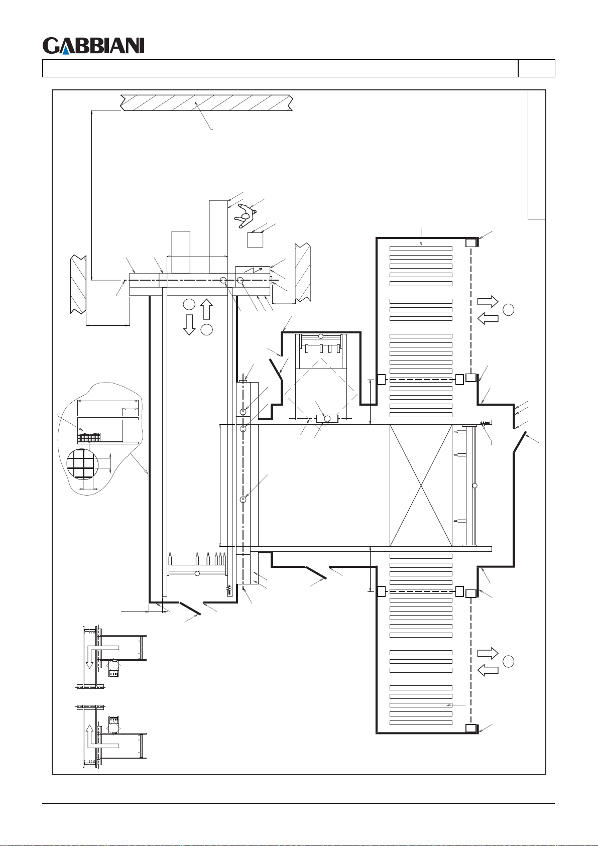
105-125
4 - TRANSPORT AND INSTALLATION
W
S (>PR+500)
L
M
G
>1600
LT
2
1
EN
L
O
OP
L
F
R
LL
x
IE1
IE
B
>500
A
A
L
IP
IP1
LAYOUT_FLEXIMA_026
4
H1
I
B
2000
RP
40
300
40
PR
min. 200
L
H
H1
G1
H
A
A
A
M
L
A1
E
G2
H
H1
y
1000
1000
y
y
y
L
x
P
L
N
H1
H
MT
P
x
L
4
LEFT CONFIGURATION
R
x
RIGHT CONFIGURATION
Cap. 4 - Pag. 30/79 THIS MANUAL IS PROPERTY OF - SCM GROUP SPA. - ANY TOTAL OR PARTIAL REPRODUCTION IS STRICTLY FORBIDDEN
Page 73
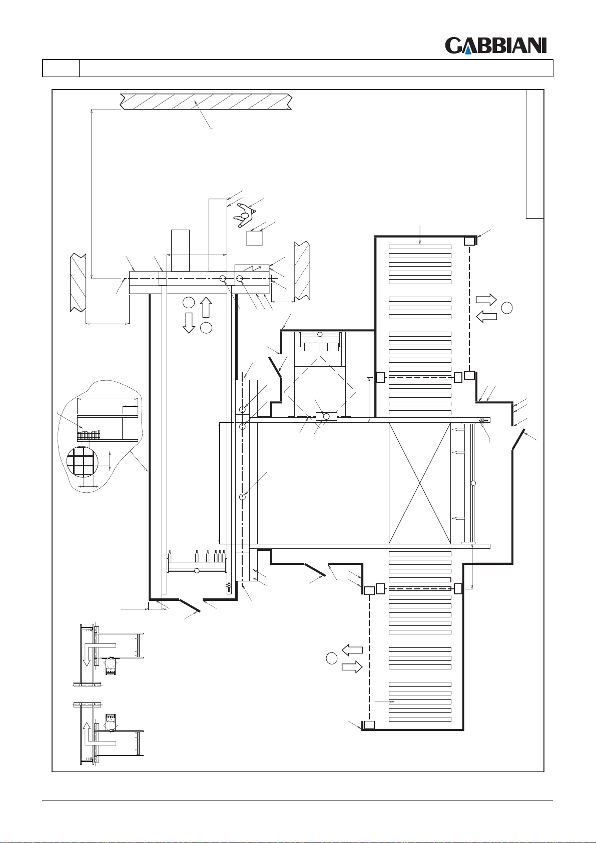
105-125
4 - TRANSPORT AND INSTALLATION
LAYOUT_FLEXIMA_027
R
L
x
4
EN
S (>PR+500)
G
>1600
W
L
O
OP
L
F
L
M
LT
2
A
IE1
IE
B
>500
A
L
IP
IP1
1
H1
I
B
2000
RP
40
300
40
PR
min. 200
L
H
H1
G1
H
x
y
1000
L
P
L
N
H1
H
MT
y
1000
y
y
x
A
A
A
M
L
A1
E
G2
H
L P
H1
4
LEFT CONFIGURATION
R
L
x
RIGHT CONFIGURATION
THIS MANUAL IS PROPERTY OF - SCM GROUP SPA. - ANY TOTAL OR PARTIAL REPRODUCTION IS STRICTLY FORBIDDEN Cap. 4 - Pag. 31/79
Page 74
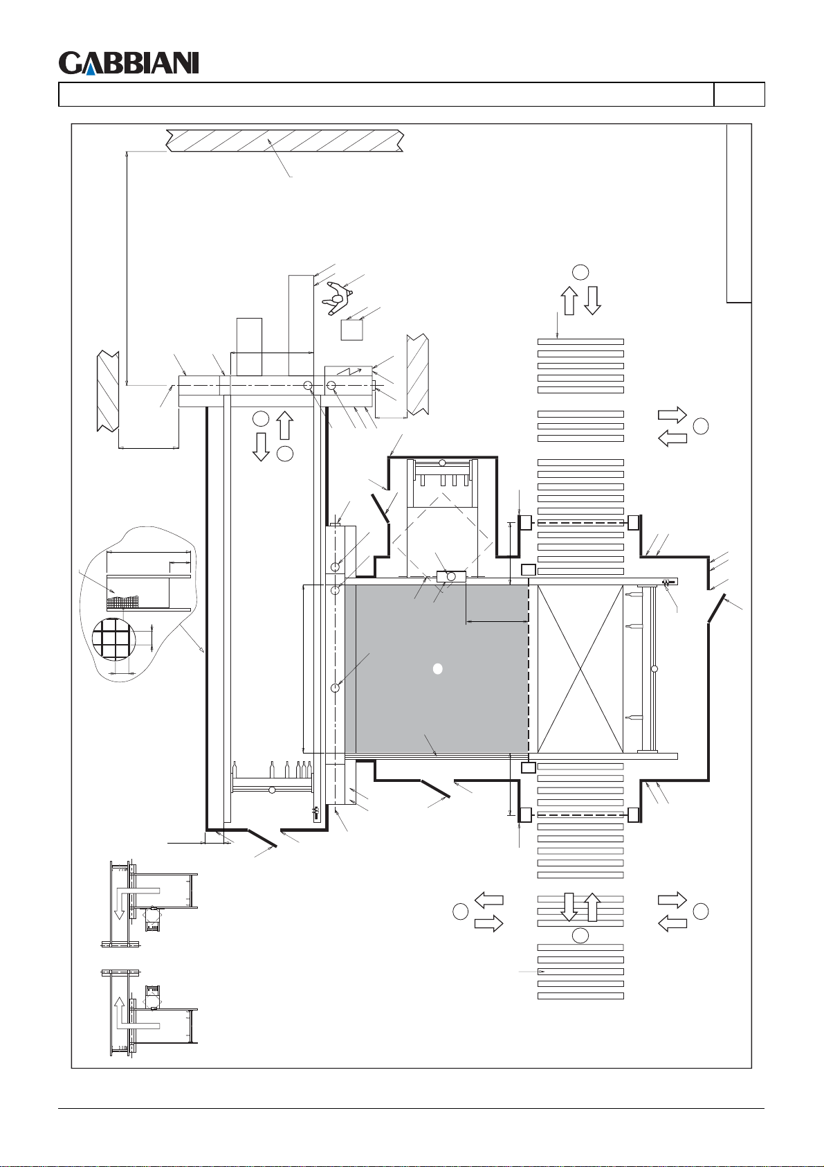
105-125
4 - TRANSPORT AND INSTALLATION
W
S (>PR+500)
L
M
G
>1600
LT
2
1
EN
L
O
OP
L
F
IE1
IE
B
>500
A
A
L
IP
IP1
4
R
LAYOUT_FLEXIMA_028
4
H1
I
B
2000
RP
40
300
40
PR
min. 200
L
H
H1
G1
H
A
A
A
M
L
A1
E
G2
T1
T
H
H1
1000
1000
1000
L
y
y
y
y
y
L
y
L
P
L
N
H1
H
MT
L
P
y
4
LEFT CONFIGURATION
RIGHT CONFIGURATION
4
4
R
Cap. 4 - Pag. 32/79 THIS MANUAL IS PROPERTY OF - SCM GROUP SPA. - ANY TOTAL OR PARTIAL REPRODUCTION IS STRICTLY FORBIDDEN
Page 75
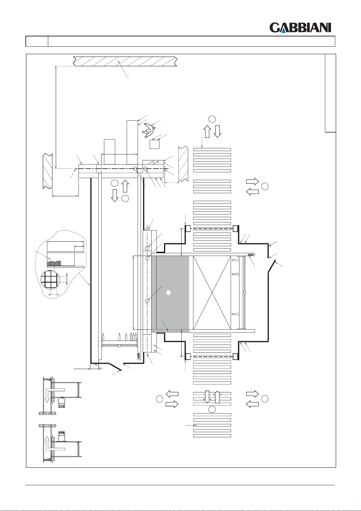
105-125
4 - TRANSPORT AND INSTALLATION
4
R
44
EN
S (>PR+500)
G
>1600
W
L
O
OP
L
F
L
M
LT
2
A
IE1
IE
B
>500
A
IP
IP1
1
LAYOUT_FLEXIMA_029
B
A
2000
RP
40
300
40
PR
min. 200
L
H
H1
A
A
T
M
L
G1
L
x
1000
T1
1000
x
L
x
L
P
L
L
H1
H
MT
L
P
x
4
LEFT CONFIGURATION
R
RIGHT CONFIGURATION
THIS MANUAL IS PROPERTY OF - SCM GROUP SPA. - ANY TOTAL OR PARTIAL REPRODUCTION IS STRICTLY FORBIDDEN Cap. 4 - Pag. 33/79
4
Page 76
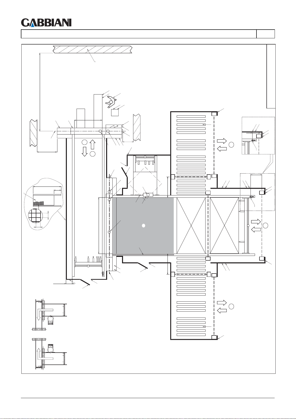
105-125
4 - TRANSPORT AND INSTALLATION
W
L
O
S (>PR+500)
L
M
G
>1600
2000
RP
300
LT
2
A
A
1
B
EN
OP
L
F
LL
x
IE1
IE
B
>500
L
IP
IP1
H1
H
A
A
A1
y
1000
R
150
4
MT
x
y
L
L
P
P
y
LAYOUT_FLEXIMA_030
L
P1
L
N
x1
850
L
N
x
40
LEFT CONFIGURATION
E
G2
40
PR
A
T1
T
y
M
L
min. 200
L
H
H1
G1
H
H1
1000
y
y
x
P
L
MT
3
x
L
4
R
x
RIGHT CONFIGURATION
Cap. 4 - Pag. 34/79 THIS MANUAL IS PROPERTY OF - SCM GROUP SPA. - ANY TOTAL OR PARTIAL REPRODUCTION IS STRICTLY FORBIDDEN
Page 77
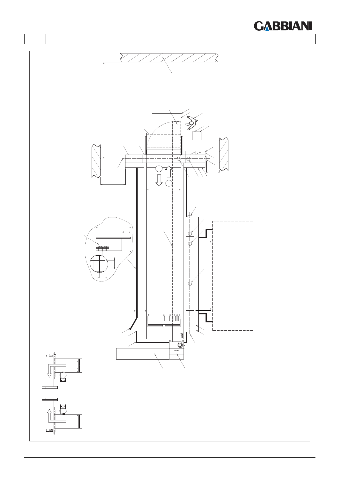
105-125
EN
W
4 - TRANSPORT AND INSTALLATION
V
S (>PR+500)
BF1
L
M
G
>1600
2000
RP
40
300
40
2
1
LT
V1
L
O
OP
L
F
IE1
IE
B
>500
A
A
IP
IP1
B
A
A
A
PR
LAYOUT_FLEXIMA_032
min.200
M
L
G1
LEFT CONFIGURATION
RIGHT CONFIGURATION
H
H1
L
V3
V2
THIS MANUAL IS PROPERTY OF - SCM GROUP SPA. - ANY TOTAL OR PARTIAL REPRODUCTION IS STRICTLY FORBIDDEN Cap. 4 - Pag. 35/79
Page 78
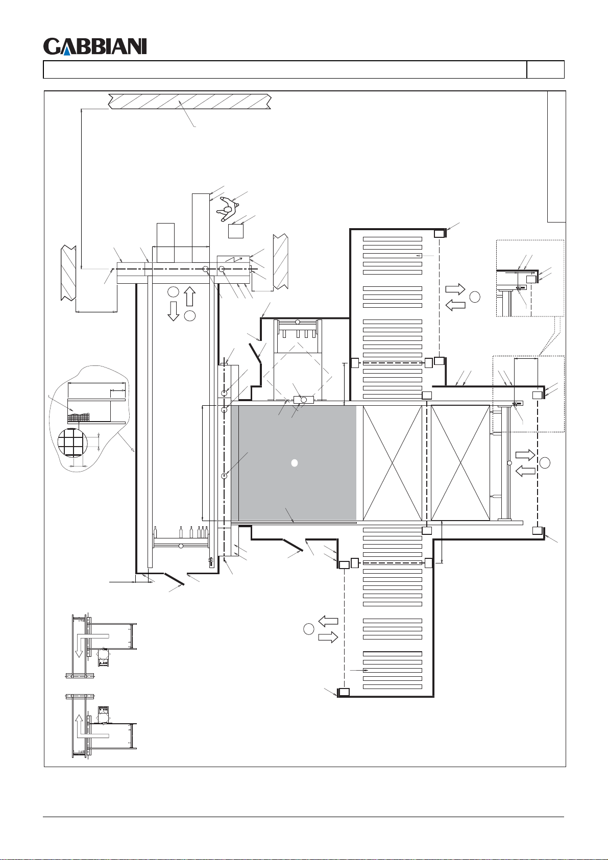
105-125
4 - TRANSPORT AND INSTALLATION
W
L
O
S (>PR+500)
L
M
G
>1100
2000
RP
300
LT
2
A
A
1
B
EN
OP
L
F
L
x
IE1
IE
B
>500
L
IP
IP1
H1
H
A
A
A1
y
1000
R
150
4
MT
x
y
L
L
P
P
y
LAYOUT_FLEXIMA_031
L
P1
L
N
x1
850
L
N
x
40
LEFT CONFIGURATION
E
G2
40
PR
A
T1
T
y
M
L
min. 200
L
H
H1
G1
H
L P
H1
y
x
1000
y
MT
3
x
L
4
R
L
x
RIGHT CONFIGURATION
Cap. 4 - Pag. 36/79 THIS MANUAL IS PROPERTY OF - SCM GROUP SPA. - ANY TOTAL OR PARTIAL REPRODUCTION IS STRICTLY FORBIDDEN
Page 79
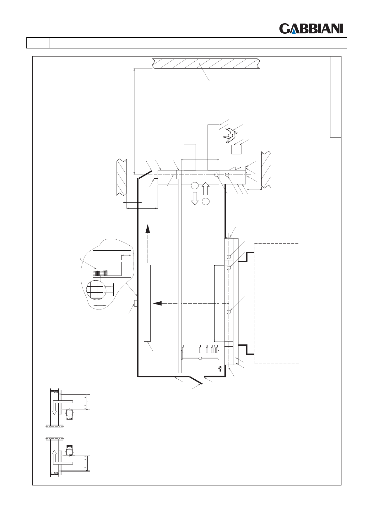
105-125
4 - TRANSPORT AND INSTALLATION
W
L
O
OP
L
F
LT
2
A
1
IE1
IE
B
>500
A
IP
IP1
LAYOUT_FLEXIMA_033
EN
S (>PR+500)
>500
H2
H1
>1600
L
M
G
B
A
2000
RP
40
300
40
PR
RH2
CR
L
H
H1
A
A
M
L
G1
LEFT CONFIGURATION
RIGHT CONFIGURATION
THIS MANUAL IS PROPERTY OF - SCM GROUP SPA. - ANY TOTAL OR PARTIAL REPRODUCTION IS STRICTLY FORBIDDEN Cap. 4 - Pag. 37/79
Page 80
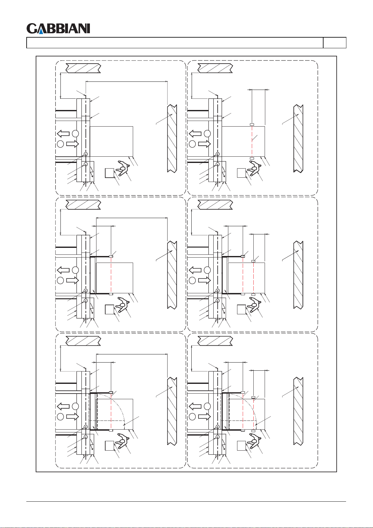
105-125
4 - TRANSPORT AND INSTALLATION
S(>PR+500)
G
>1600
M
>1600
EN
G
M
500
1
A
A
IP
IP1
>1600
1
L
W
2
2
L
W
BF
1
L
O
L
OP
F
IE1
B
IE
S(>PR+500)
G
850
M
L
BF1
W
2
A
A
IP
IP1
>1600
L
O
L
OP
F
IE1
IE
B
G
850
M
L
BF1
500
BF
W
2
1
A
A
IP
IP1
>1600
1
A
A
IP
IP1
U
IE1
B
IE
S(>PR+500)
G
850
M
L
BF1
L
O
L
OP
F
W
2
V
U U
IE1
IE
B
L
O
L
OP
F
A
A
IP
IP1
>1600
1
A
A
IP
IP1
B
G
2
B
U
IE1
IE
850
M
L
BF1
IE1
IE
L
O
L
OP
F
500
BF
L
OP
F
W
V
L
O
Cap. 4 - Pag. 38/79 THIS MANUAL IS PROPERTY OF - SCM GROUP SPA. - ANY TOTAL OR PARTIAL REPRODUCTION IS STRICTLY FORBIDDEN
Page 81
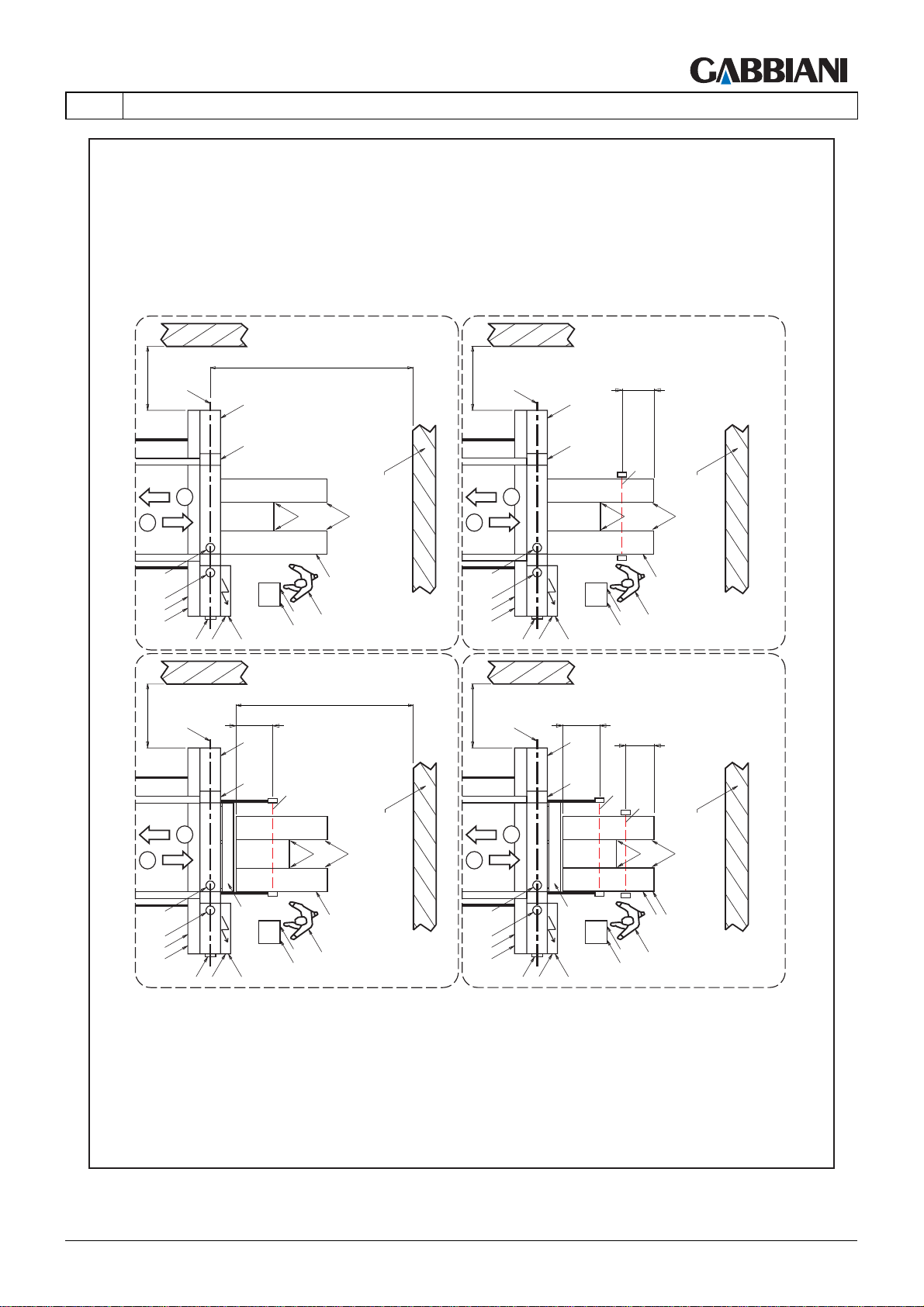
105-125
4 - TRANSPORT AND INSTALLATION
G
M
500
EN
>1600
S(>PR+500)
G
M
>1600
1
IP
IP1
>1600
1
L
W
1
A
A
IP
IP1
>1600
1
2
B
G
2
2
L
A
A
IE1
B
IE
G
850
M
L
L
F
S(>PR+500)
BF1
L
O
OP
W
2
L
L
L
BF
L
L
OP
F
IE1
IE
850
M
L
500
BF1
BF
L
W
L
O
W
L
A
A
IP
IP1
B
THIS MANUAL IS PROPERTY OF - SCM GROUP SPA. - ANY TOTAL OR PARTIAL REPRODUCTION IS STRICTLY FORBIDDEN Cap. 4 - Pag. 39/79
U
IE1
IE
O
L
OP
F
IP1
A
A
IP
B
U
IE1
IE
L
O
L
OP
F
Page 82
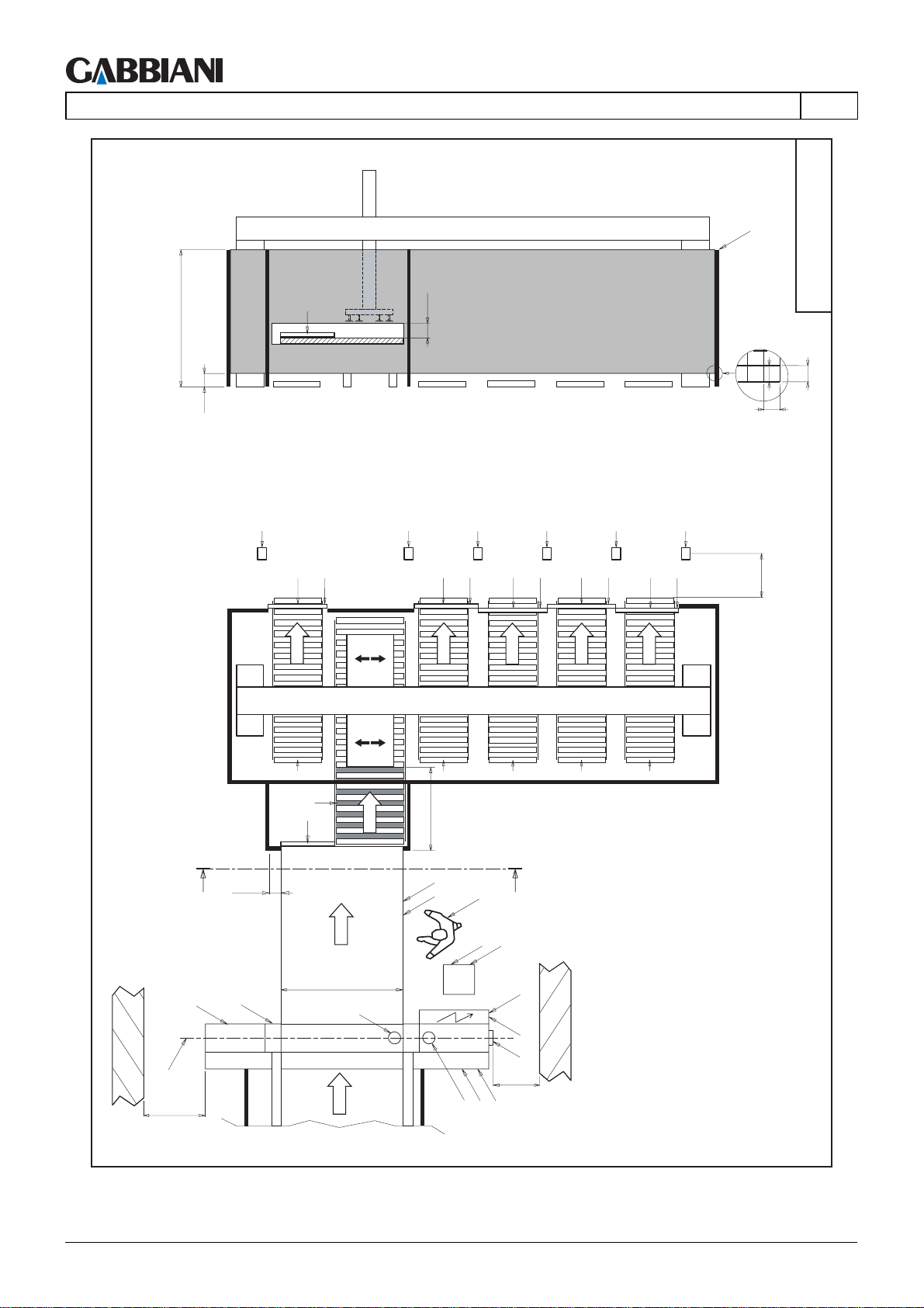
105-125
4 - TRANSPORT AND INSTALLATION
EN
Z-Z
RP
2000
300
L,R5,RL1
BA
L1
L2
<300
40
L
L1
L,R4,RL1
L2
L1
L,R3,RL1
L2
L1
L,R2,RL1
L2
L1
L,R1,RL1
L2
>850
UNLOADING UNIT_1
40
G
>1600
R
CH
BA
>120
Z
LT
M
L
A
R
>850
L
O
A
R
OP
Z
L
F
IE1
IE
B
>500
IP
IP1
R
R
Cap. 4 - Pag. 40/79 THIS MANUAL IS PROPERTY OF - SCM GROUP SPA. - ANY TOTAL OR PARTIAL REPRODUCTION IS STRICTLY FORBIDDEN
Page 83
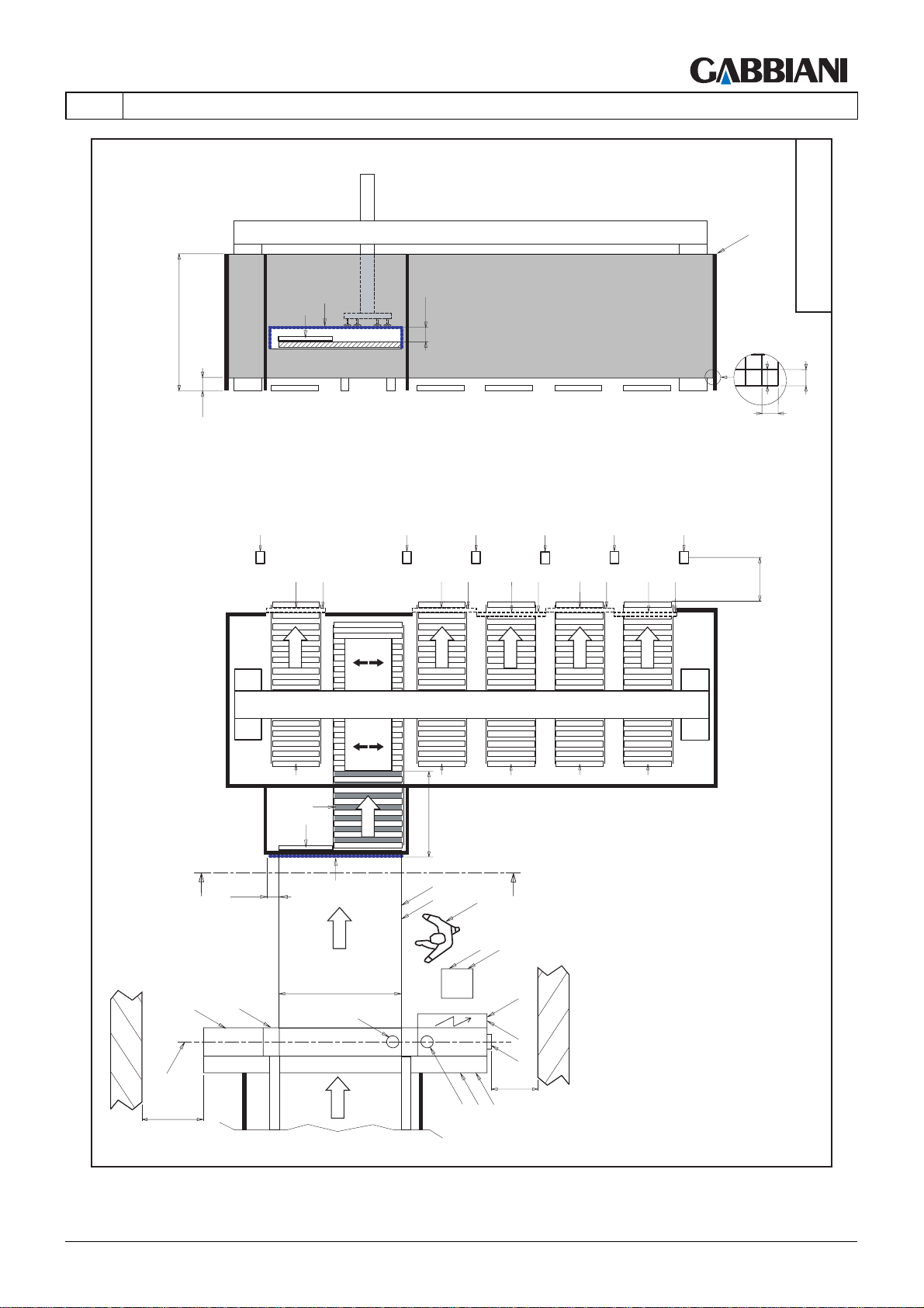
105-125
EN
Z-Z
4 - TRANSPORT AND INSTALLATION
RP
2000
300
L+R5+RL1
DS
BA
L1
L2
<300
40
L
L1
L,R4,RL1
L2
L1
L,R3,RL1
L2
L1
L,R2,RL1
L2
L1
L,R1,RL1
L2
>850
UNLOADING UNIT_1A
40
G
>1600
R
CH
BA
R
R
R
R
550÷850
>120
DS
Z
LT
L
M
A
L
O
OP
Z
L
F
IE1
IE
B
>500
A
IP
IP1
THIS MANUAL IS PROPERTY OF - SCM GROUP SPA. - ANY TOTAL OR PARTIAL REPRODUCTION IS STRICTLY FORBIDDEN Cap. 4 - Pag. 41/79
Page 84
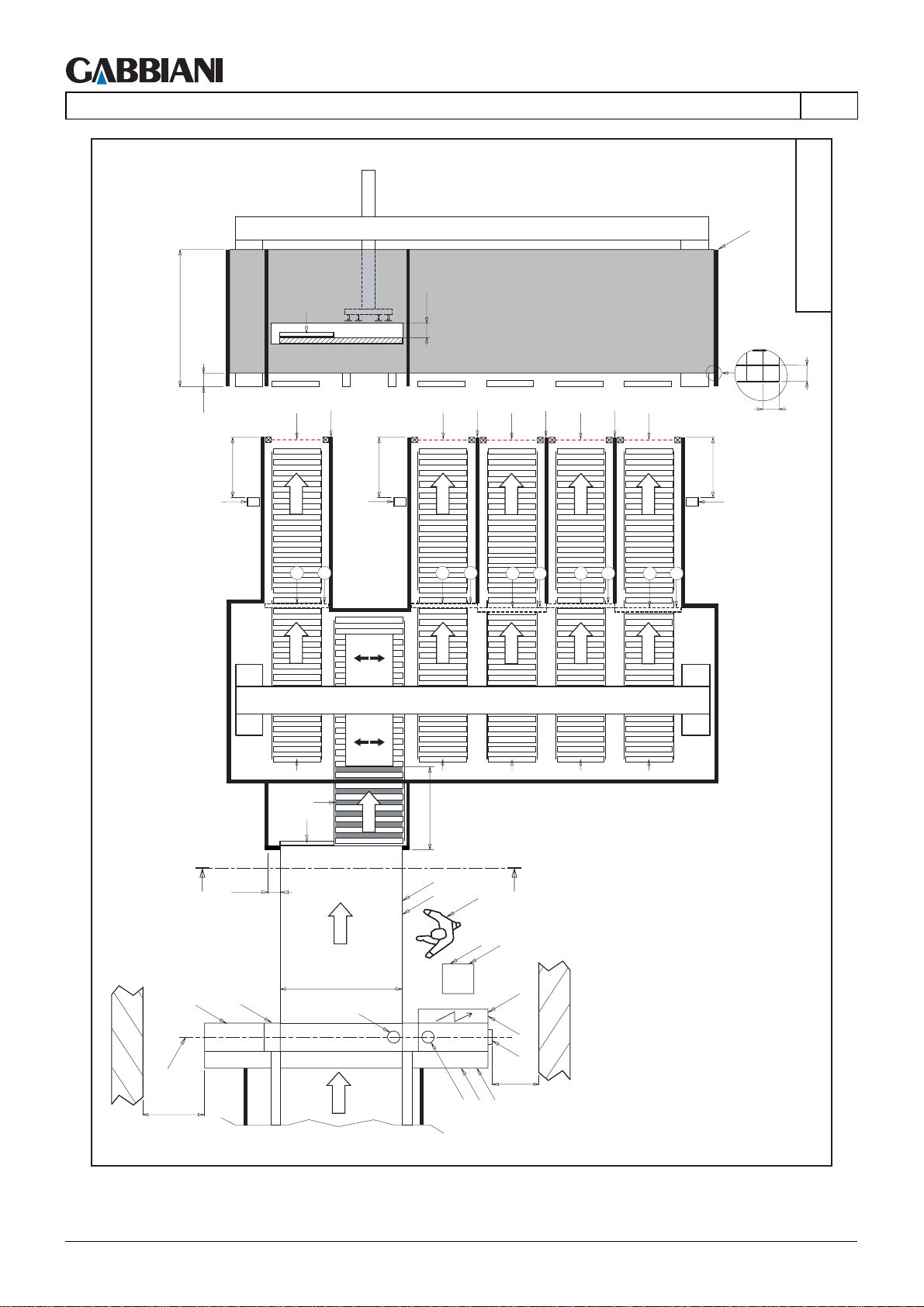
105-125
4 - TRANSPORT AND INSTALLATION
EN
Z-Z
RP
2000
300
RI3,L,R5
>850
BA
L
I3
>850
RI3,L,R3,R4
I1
I2
<300
L
I3
I1
I2
L
I3
I1
I2
L
I3
I1
I3
>850
I2
I1
I2
40
RI3,L,R1,R2
UNLOADING UNIT_2
40
G
>1600
R
CH
BA
>120
Z
LT
M
L
A
R
>850
L
O
A
R
OP
Z
L
F
IE1
IE
B
>500
IP
IP1
R
R
Cap. 4 - Pag. 42/79 THIS MANUAL IS PROPERTY OF - SCM GROUP SPA. - ANY TOTAL OR PARTIAL REPRODUCTION IS STRICTLY FORBIDDEN
Page 85
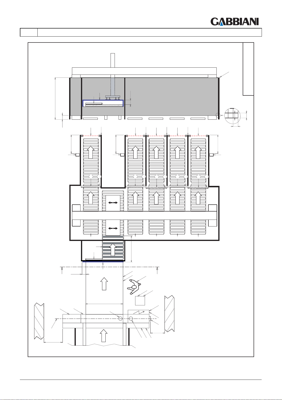
105-125
4 - TRANSPORT AND INSTALLATION
I
RP
UNLOADING UNIT_2A
40
EN
2000
BA
DS
Z-Z
U
<300
<300
300
RI3,L,R5
>850
L
I3
>850
RI3,L,R3,R4
I1
I2
R
CH
BA
L
I3
I1
I2
R
L
I3
I1
I2
R
L
I3
I1
R
I3
>850
I2
I1
I2
R
40
RI3,L,R1,R2
550÷850
>120
DS
Z
LT
M
G
>1600
THIS MANUAL IS PROPERTY OF - SCM GROUP SPA. - ANY TOTAL OR PARTIAL REPRODUCTION IS STRICTLY FORBIDDEN Cap. 4 - Pag. 43/79
L
A
L
O
OP
Z
L
F
IE1
IE
B
>500
A
IP
IP1
Page 86
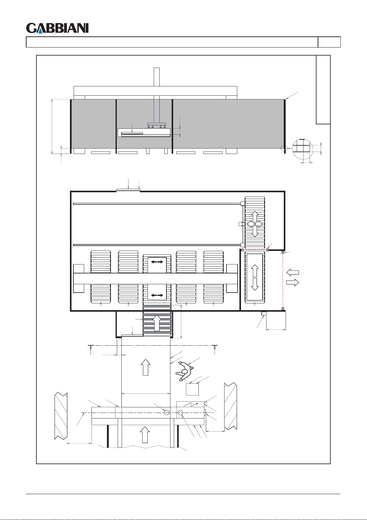
105-125
4 - TRANSPORT AND INSTALLATION
EN
Z-Z
RP
2000
300
L1a
BA
L2a
<300
UNLOADING UNIT_3
40
40
Y2
X2
G
>1600
R
>120
Z
M
L
R
CH
BA
LT
A
R
>850
L
O
R
OP
Z
L
F
IE1
IE
B
>500
A
IP
IP1
R
>850
P2
Cap. 4 - Pag. 44/79 THIS MANUAL IS PROPERTY OF - SCM GROUP SPA. - ANY TOTAL OR PARTIAL REPRODUCTION IS STRICTLY FORBIDDEN
Page 87
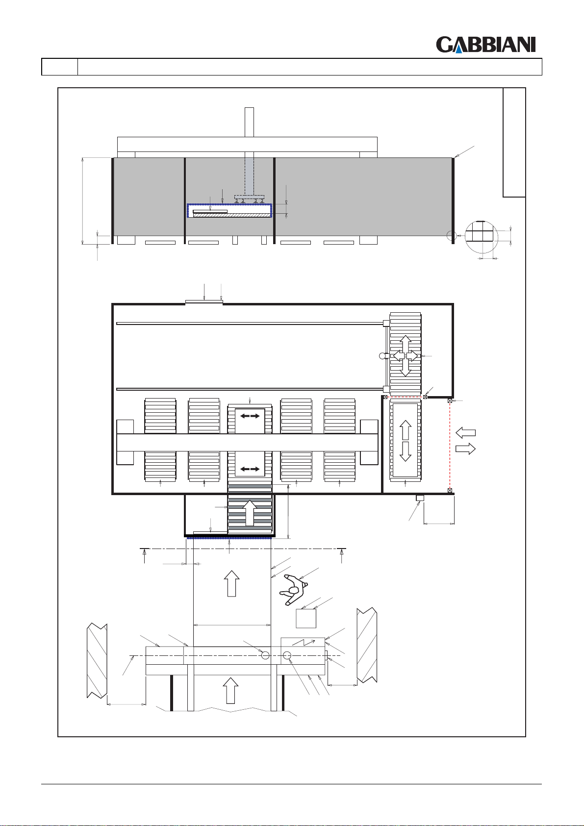
105-125
EN
Z-Z
4 - TRANSPORT AND INSTALLATION
RP
2000
300
L1a
BA
DS
L2a
<300
40
RT
T
Y2
X2
UNLOADING UNIT_3A
40
G
>1600
R
>120
Z
M
L
R
R
CH
BA
R
550÷850
DS
LT
A
L
O
R
OP
Z
L
F
IE1
IE
B
>500
A
IP
IP1
R
>850
P2
THIS MANUAL IS PROPERTY OF - SCM GROUP SPA. - ANY TOTAL OR PARTIAL REPRODUCTION IS STRICTLY FORBIDDEN Cap. 4 - Pag. 45/79
Page 88
105-125
4 - TRANSPORT AND INSTALLATION
EN
4.2 TRANSPORT, PACKAGING AND UNPACKING
(42.0)
The machine may be shipped in different types of packaging:
Panel saw base (TT, TL)
A1 - Wooden platform
Inlet bench TT, TL outfeed table surface, panel saw pusher TT
A2 - Wooden platform
Panel saw pusher TT
A3 - Wooden platform
Elevator table, panel saw pusher TL
A4 - Wooden platform
Outlet bench TL
A5 - Wooden platform
Panel saw shoulders (TT, TL), TL outfeed tables, TL tables structure
A6 - Wooden platform
Trim cut cutter
A7 - Wooden platform
Tilting conveyor belt
A8 - Wooden platform
Gantry structure
B1 - Iron feet
Gripper frame
B2 - Wooden platform
Gantry support legs
B3 - Wooden platform
Electric cabinet
B4 - Wooden platform
Safety fences
B5 - Wooden platform
When necessary, the machine is wrapped in plastic material to protect it against atmospheric agents.
Before assembling the various parts, the greasy substances with which they are covered must be cleaned off,
especially where unpainted or sliding parts are concerned.
CAUTION: These parts must be cleaned with special solvents. Do not use substances such as
thinners since they are a health hazard and ruin gaskets, rubber parts and paintwork.
Cap. 4 - Pag. 46/79 THIS MANUAL IS PROPERTY OF - SCM GROUP SPA. - ANY TOTAL OR PARTIAL REPRODUCTION IS STRICTLY FORBIDDEN
Page 89
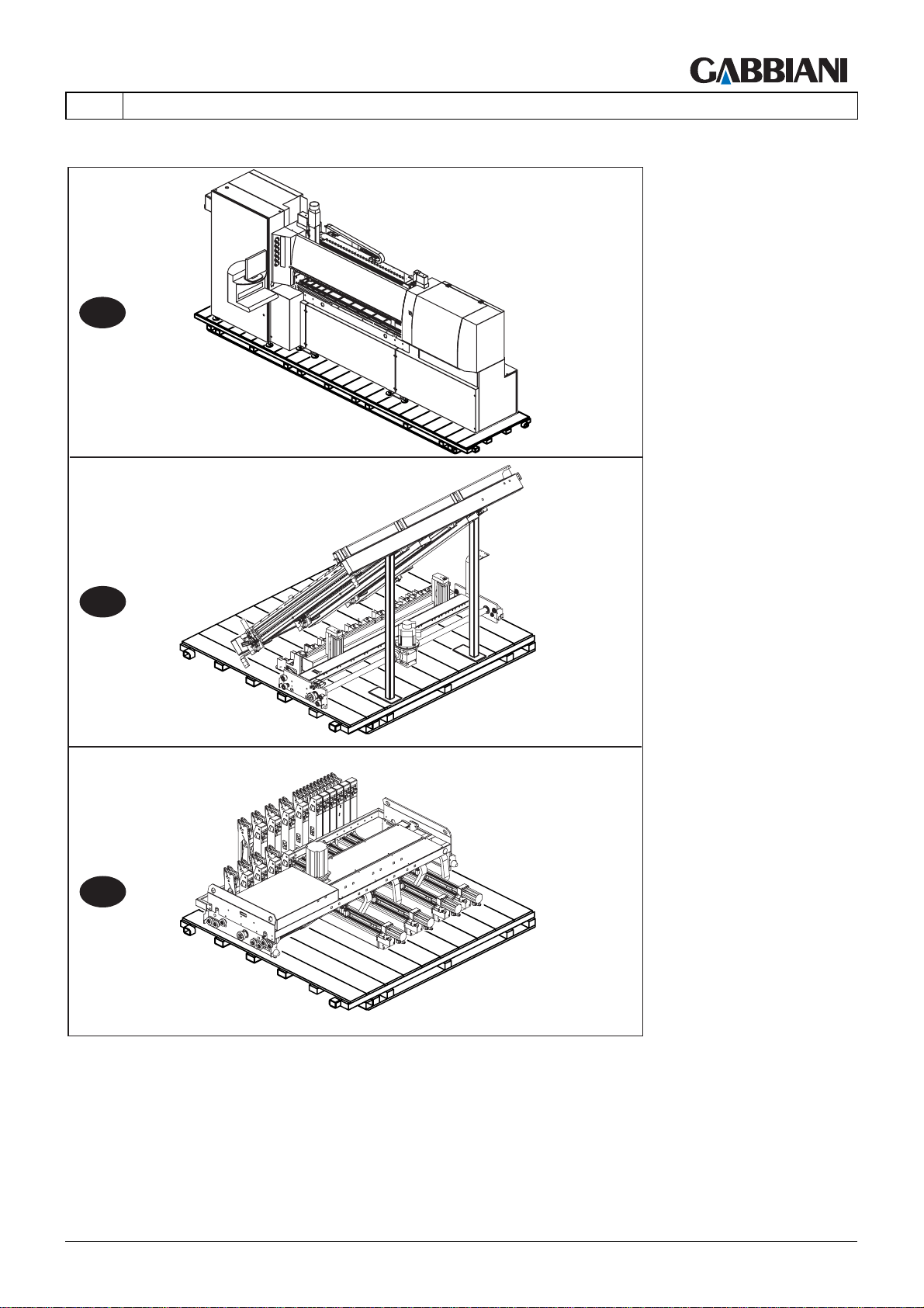
105-125
EN
4 - TRANSPORT AND INSTALLATION
A1
A2
A3
Fig. 4.2a
THIS MANUAL IS PROPERTY OF - SCM GROUP SPA. - ANY TOTAL OR PARTIAL REPRODUCTION IS STRICTLY FORBIDDEN Cap. 4 - Pag. 47/79
Page 90
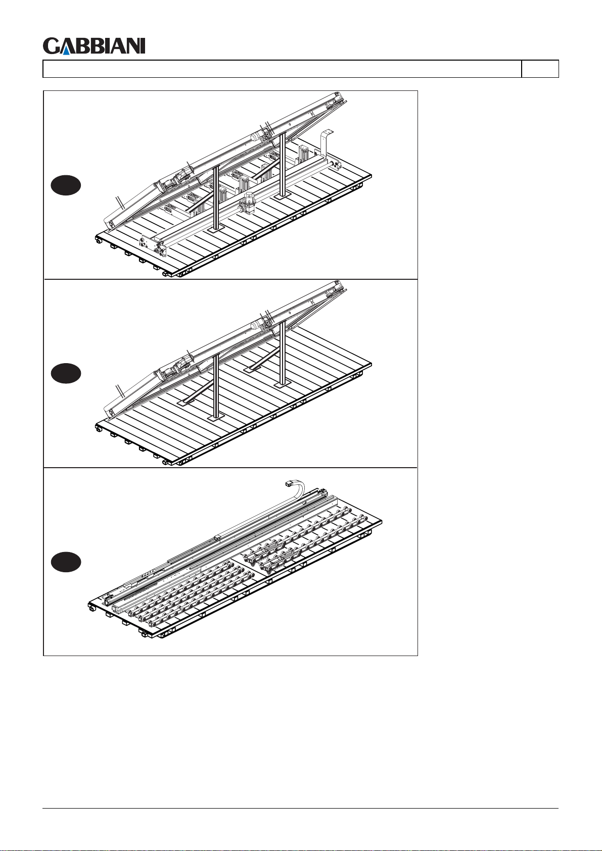
105-125
4 - TRANSPORT AND INSTALLATION
A4
EN
A5
A6
Fig. 4.2b
Cap. 4 - Pag. 48/79 THIS MANUAL IS PROPERTY OF - SCM GROUP SPA. - ANY TOTAL OR PARTIAL REPRODUCTION IS STRICTLY FORBIDDEN
Page 91
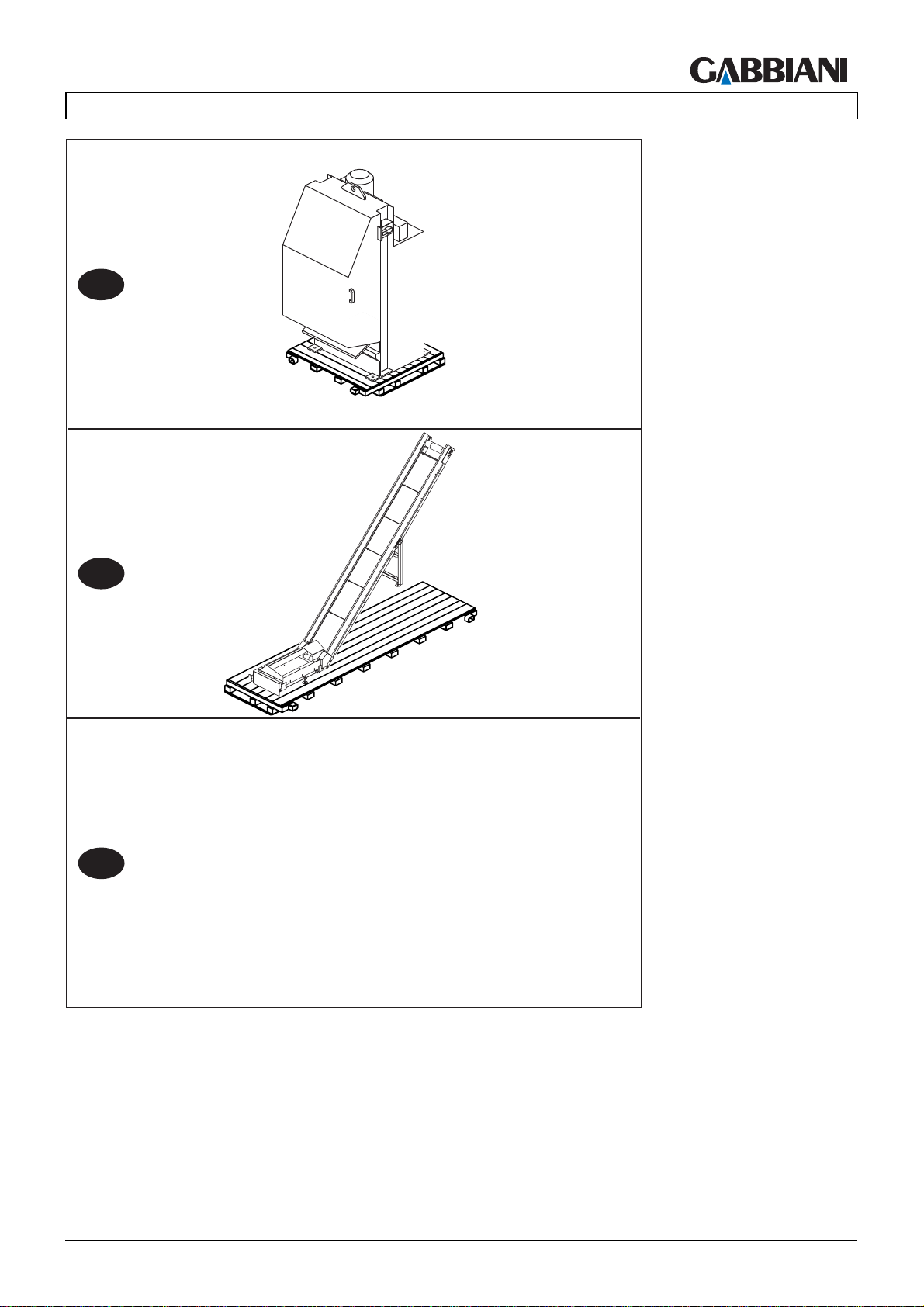
105-125
EN
4 - TRANSPORT AND INSTALLATION
A7
A8
A9
Fig. 4.2c
THIS MANUAL IS PROPERTY OF - SCM GROUP SPA. - ANY TOTAL OR PARTIAL REPRODUCTION IS STRICTLY FORBIDDEN Cap. 4 - Pag. 49/79
Page 92
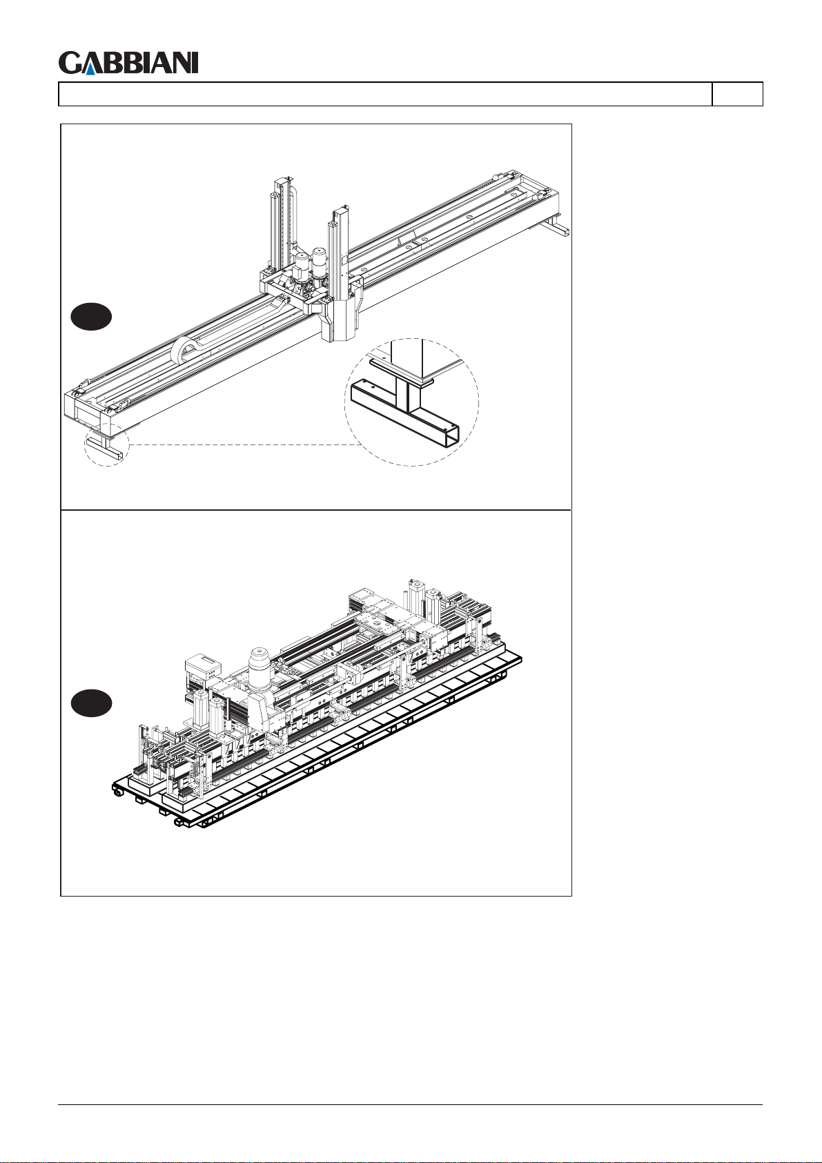
105-125
4 - TRANSPORT AND INSTALLATION
B1
EN
B2
Fig. 4.2d
Cap. 4 - Pag. 50/79 THIS MANUAL IS PROPERTY OF - SCM GROUP SPA. - ANY TOTAL OR PARTIAL REPRODUCTION IS STRICTLY FORBIDDEN
Page 93
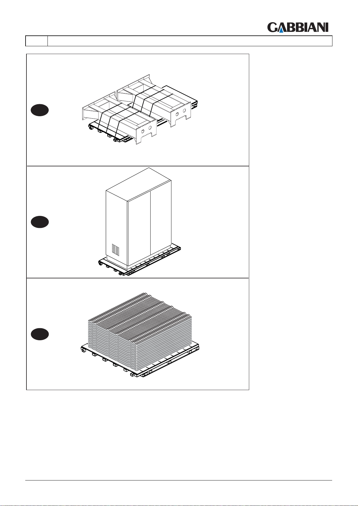
105-125
EN
4 - TRANSPORT AND INSTALLATION
B3
B4
B5
Fig. 4.2e
THIS MANUAL IS PROPERTY OF - SCM GROUP SPA. - ANY TOTAL OR PARTIAL REPRODUCTION IS STRICTLY FORBIDDEN Cap. 4 - Pag. 51/79
Page 94

105-125
4 - TRANSPORT AND INSTALLATION
EN
4.3 MOVING THE MACHINE
(43.0)
HAZARD
To lift and move the machine use suitable means and personnel trained for these operations.
Arrange for a bridge crane and a truck of suitable capacity.
Check that the crane has a sufficient lifting capacity. This is indicated on the “mass of the machine
part” plate (see section 1.4.2).
The machine weight is indicated in this manual as well as on the identification plate.
Panel saw base (TT, TL). (Fig. 4.3a)
- Insert the two rods A provided with the machine
- Fit the two collars B on each rod
- Tighten the grub screws C.
- Lift with a bridge crane
Or:
- Lift with a lift truck.
Cap. 4 - Pag. 52/79 THIS MANUAL IS PROPERTY OF - SCM GROUP SPA. - ANY TOTAL OR PARTIAL REPRODUCTION IS STRICTLY FORBIDDEN
Page 95
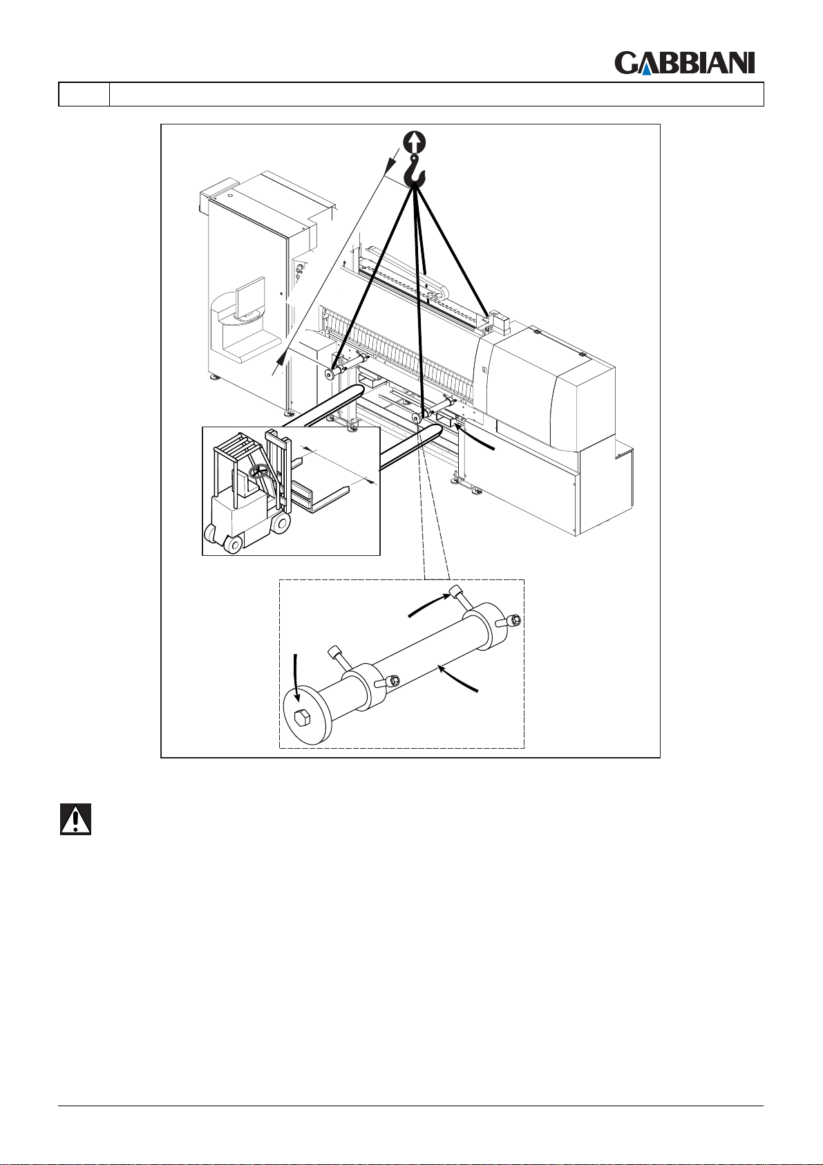
105-125
EN
4 - TRANSPORT AND INSTALLATION
> 2500 mm
1000 mm
S
C
B
A
Fig. 4.3a
HAZARD: Remove the brackets S (Fig. 4.3a) before starting the machine.
THIS MANUAL IS PROPERTY OF - SCM GROUP SPA. - ANY TOTAL OR PARTIAL REPRODUCTION IS STRICTLY FORBIDDEN Cap. 4 - Pag. 53/79
Page 96
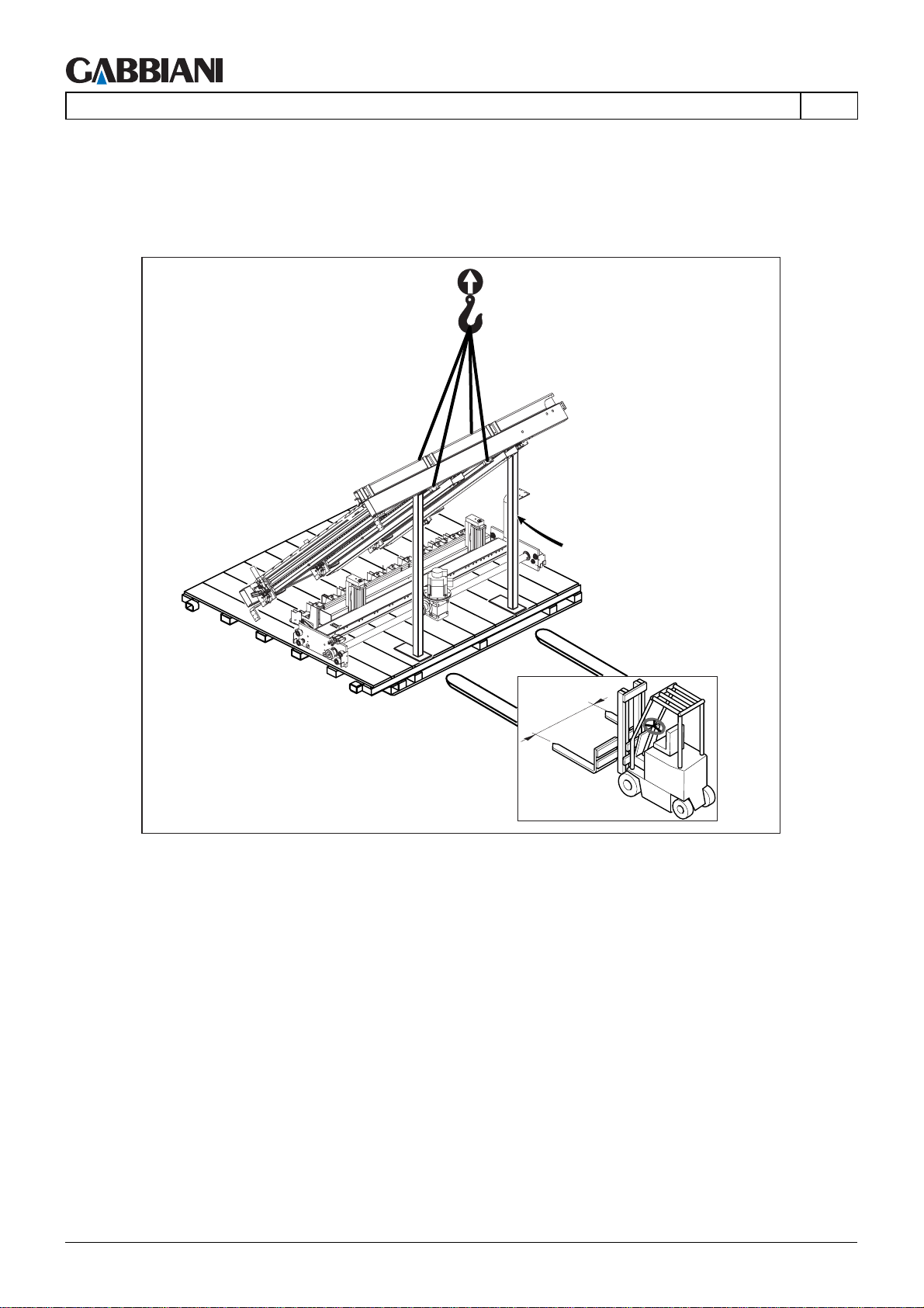
105-125
4 - TRANSPORT AND INSTALLATION
Inlet bench TT, TL outfeed table surface, panel saw pusher TT (Fig. 4.3b)
Move using a fork lift truck, insert the forks in the points indicated for lifting. Minimum centre to centre between
forks and fork lift must be 1500 mm.
Before removing the tubular supports (ts), make sure the TT infeed tables are supported by a bridge crane to stop
them from falling.
EN
ts
1500 mm
Fig. 4.3b
Cap. 4 - Pag. 54/79 THIS MANUAL IS PROPERTY OF - SCM GROUP SPA. - ANY TOTAL OR PARTIAL REPRODUCTION IS STRICTLY FORBIDDEN
Page 97
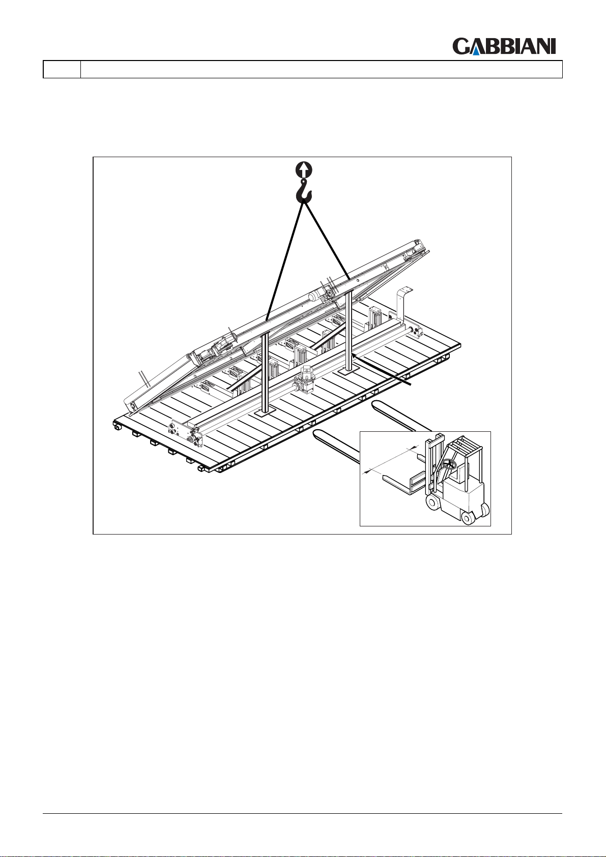
105-125
EN
Elevator table, panel saw pusher TL (Fig. 4.3d)
Move using a fork lift truck, insert the forks in the points indicated for lifting. Minimum centre to centre between
forks and fork lift must be 1500 mm.
Before disassembling tubular support frame (ts) support elevator table with a crane trolley so that it does not fall.
4 - TRANSPORT AND INSTALLATION
ts
1500 mm
Fig. 4.3d
THIS MANUAL IS PROPERTY OF - SCM GROUP SPA. - ANY TOTAL OR PARTIAL REPRODUCTION IS STRICTLY FORBIDDEN Cap. 4 - Pag. 55/79
Page 98
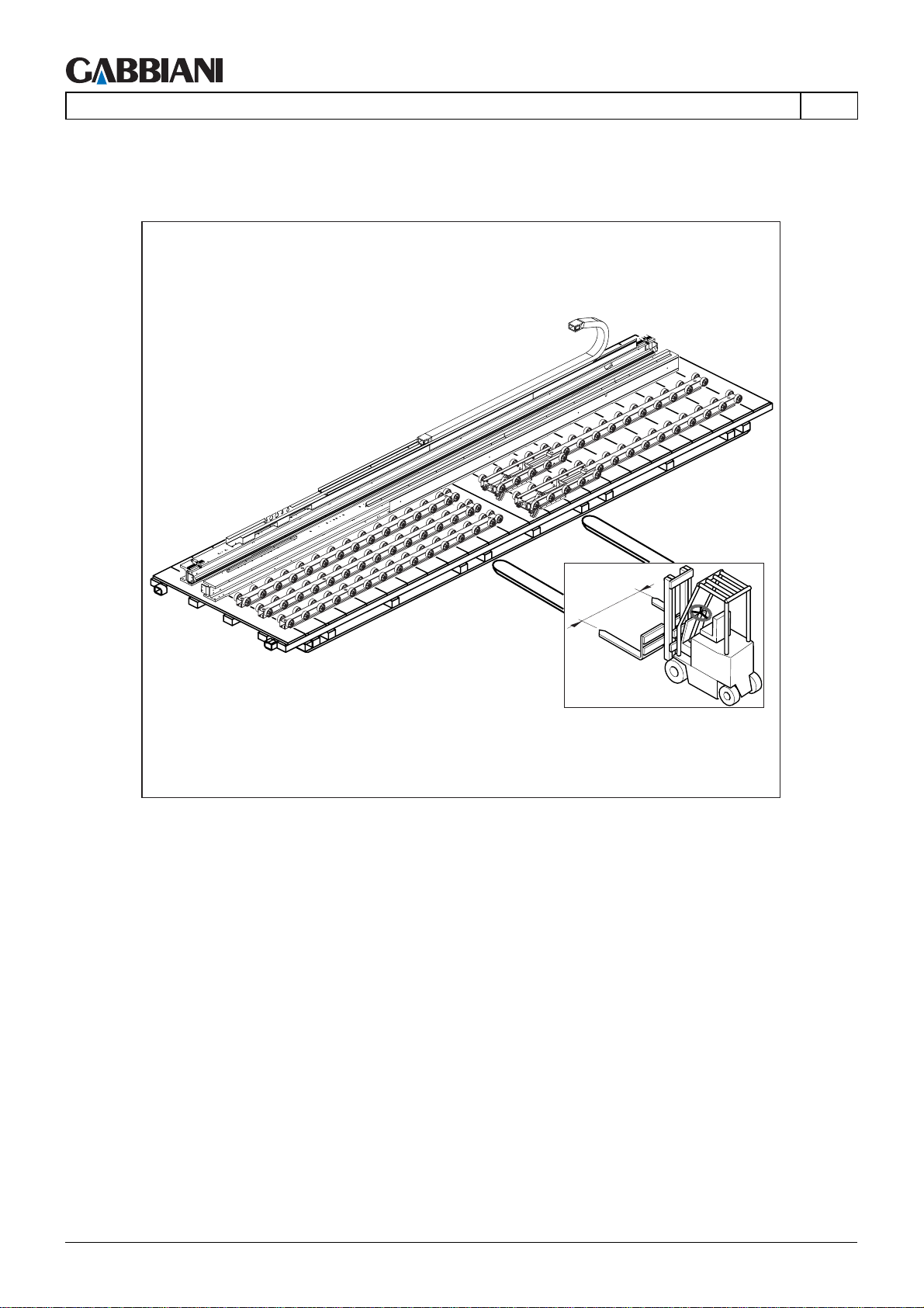
105-125
4 - TRANSPORT AND INSTALLATION
Panel saw shoulders (TT, TL), TL outfeed tables, TL tables structure (Fig. 4.3e)
Move using a fork lift truck, insert the forks in the points indicated for lifting. Minimum centre to centre between
forks and fork lift must be 1500 mm.
EN
1500 mm
Fig. 4.3e
Cap. 4 - Pag. 56/79 THIS MANUAL IS PROPERTY OF - SCM GROUP SPA. - ANY TOTAL OR PARTIAL REPRODUCTION IS STRICTLY FORBIDDEN
Page 99
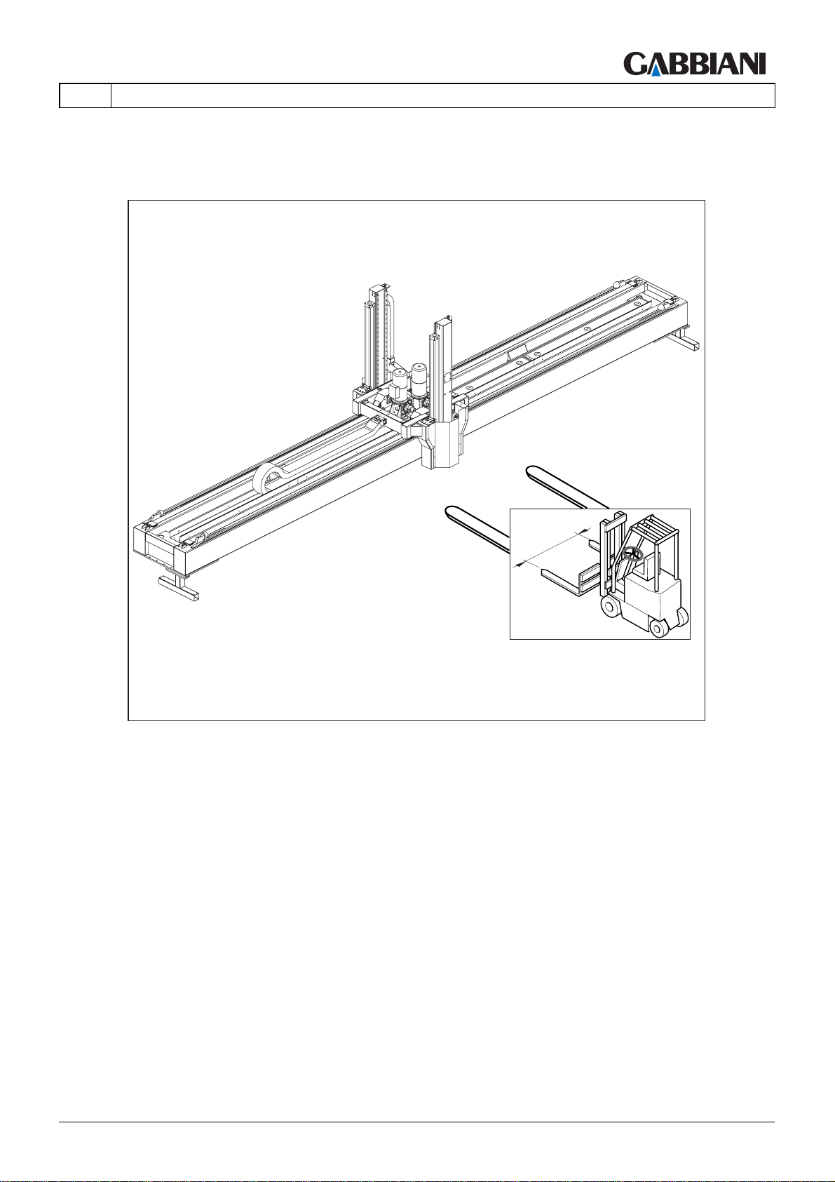
105-125
EN
Gantry structure
Move using a fork lift truck, insert the forks in the points indicated for lifting. Minimum centre to centre between
forks and fork lift must be 1500 mm.
4 - TRANSPORT AND INSTALLATION
1500 mm
Fig. 4.3g
THIS MANUAL IS PROPERTY OF - SCM GROUP SPA. - ANY TOTAL OR PARTIAL REPRODUCTION IS STRICTLY FORBIDDEN Cap. 4 - Pag. 57/79
Page 100
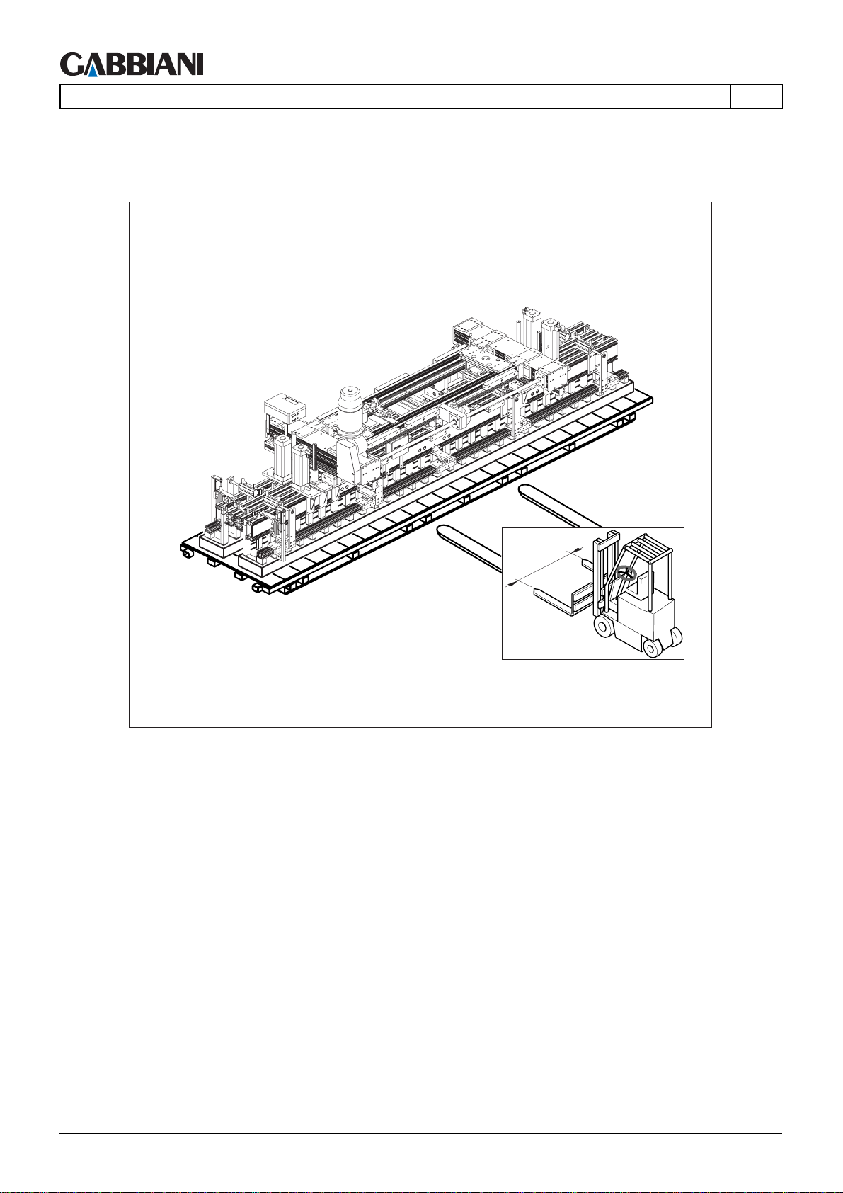
105-125
4 - TRANSPORT AND INSTALLATION
Gripper frame
Move using a fork lift truck, insert the forks in the points indicated for lifting. Minimum centre to centre between
forks and fork lift must be 1500 mm.
EN
1500 mm
Fig. 4.3h
Cap. 4 - Pag. 58/79 THIS MANUAL IS PROPERTY OF - SCM GROUP SPA. - ANY TOTAL OR PARTIAL REPRODUCTION IS STRICTLY FORBIDDEN
 Loading...