

Page 1

IPM650
Intelligent Panel Mount Display
Sensor Solutions Source
Load · Torque · Pressure · Multi-Axis · Calibration · Instruments · Software
www.futek.com
Quick Start Guide
Page 2

Getting Help
TECHNICAL SUPPORT
For more IPM650 support, please visit: http://www.futek.com/ipm650/support.aspx
02.12.08-13-0.0.
FUTEK reserves the right to modify its design and specifi cations without notice.
Please visit http://www.futek.com/salesterms for complete terms and conditions.
10 Thomas, Irvine, CA 92618 USA
Tel: (949) 465-0900
Fax: (949) 465-0905
www.futek.com
2
Page 3

Display Features
3
1
16×4 Character LCD
2
Active Channel Number
3
Peak Value
4
Tracking Value
5
Valley Value
6
Sampling Rate
TIPS FOR DISPLAY AND KEY FUNCTIONS
IPM650
1
+2.00001 Peak
+2.00000 mV/V
2
+1.99999 Valley
01 Gross 5 SPS
Channel
Enter
Reset Menu
Exit
Shunt
Tare/Gross
Track/Hold
Display
Back
Unit
Power
3
4
5
6
The Units button can change between
similar units.
Hold will fl ash on the LCD when active.
Shunt will be displayed on the LCD
when active.
The Tare function can be used to zero
out a sensor’s no load state, or to
account for a fi xture.
3
Page 4
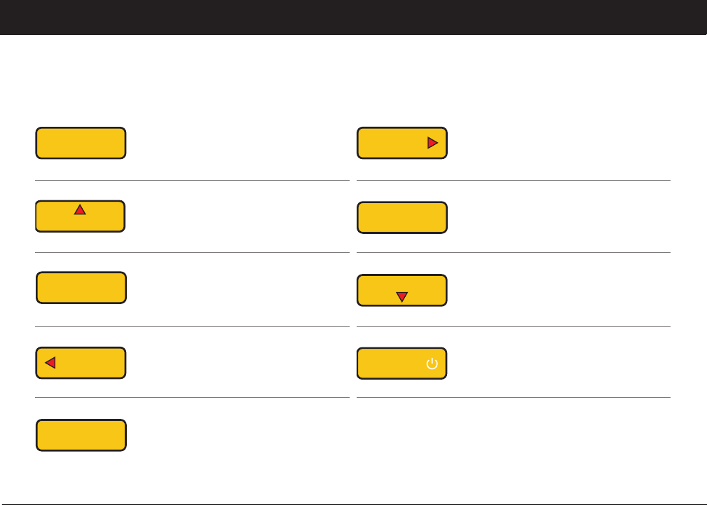
Buttons
4
Channel
Enter
Tare/Gross
Display
Back
Reset
Menu
Displays Channel Information
IN MENU MODE: Enter
Toggles between displaying the tare and gross
values. Used to remove any fi xture weights.
IN MENU MODE: ▲ Arrow
Changes display to show peak, tracking,
valley, or all values
IN MENU MODE: Back
Resets peak/valley
IN MENU MODE: ◀ Arrow
Start navigation
IN MENU MODE: n/a
Unit
Exit
Shunt
Track/Hold
Power
Toggles between engineering units (force,
torque, pressure, and displacement) and the
standard mV/V.
IN MENU MODE: ▶ Arrow
Performs a shunt action using internal resistor
IN MENU MODE: Exit
Freezes the current reading. HOLD will appear
on the LCD when active. Pressing any key on
the keypad will cancel the hold command.
IN MENU MODE: ▼ Arrow
ON/OFF
IN MENU MODE: ON/OFF
Page 5
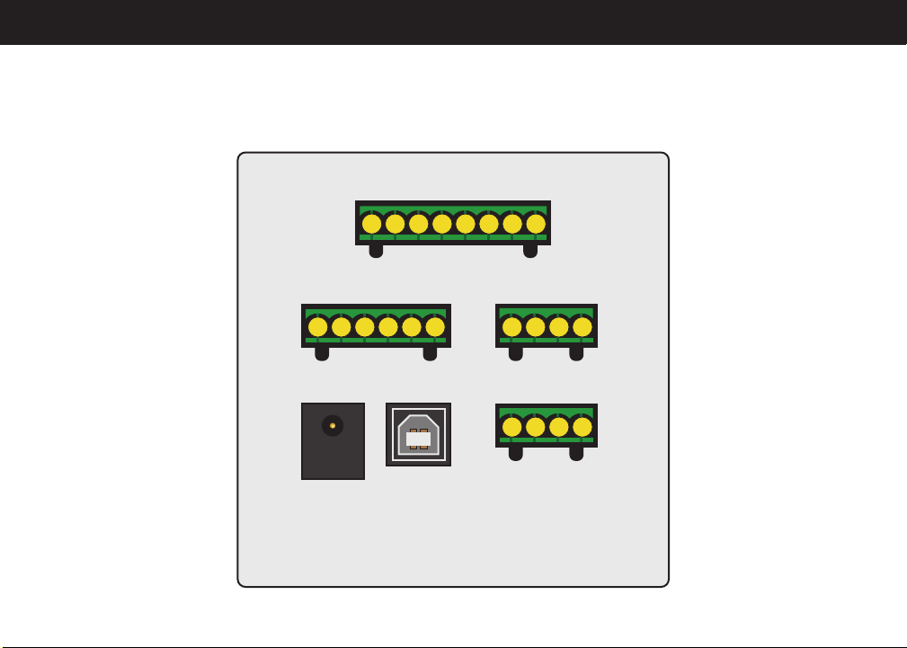
Connector Pin Confi guration
Amplifi ed Input (page 6)
A1
A2
A3
A4
A5B5A6B6A7 A8
Strain Gauge Input
(page 6)
B1 C1
B2 C2
B3 C3
B4 C4
Power
USB
Adapter
Relays
(page 7)
D1
D2
D3
D4
Analog Output
(page 7)
5
Page 6
Wiring Layout
AMPLIFIED INPUT
PIN SYMBOL DESCRIPTION
A1 G Ground
A2 G Ground
A3 24V OUT 24VDC Output
A4 5V OUT 5VDC Output
A5 –V –V from sensor
A6 +V +V from sensor
A7 PLEAD n/a
A8 PLAG n/a
6
STRAIN GAUGE INPUT
PIN SYMBOL DESCRIPTION
B1 G Ground
B2 TEDS TEDS Data
B3 –S –Signal
B4 +S +Signal
B5 –E –Excitation
B6 +E +Excitation
Page 7

RELAYS
7
PIN SYMBOL DESCRIPTION
C1 –R2 Solid State Relay 2 (–)
C2 +R2 Solid State Relay 2 (+)
C3 –R1 Solid State Relay 1 (–)
C4 +R1 Solid State Relay 1 (+)
TIPS FOR WIRING
ANALOG OUTPUT
PIN SYMBOL DESCRIPTION
D1 –VOUT Voltage Output (–)
D2 +VOUT Voltage Output (+)
D3 G Ground (current)
D4 IOUT Current Output
Ground (G) connections can be used to
connect a cable shield.
Strain Gauge Input is for sensors with a
mV/V output level.
Green screw terminals can be
removed to allow easy access to
connect the wires.
7
Page 8

Profi le Quick Setup (Calibration)
The IPM650 can store up to 15 profi les with channel 2 through 15 being user selectable.
1. Menu
2. Sensor Profi le
3. New Channel
4. Set channels using left and right
arrow keys followed by Enter
5. Sensor Confi g and choose sensor
output type
6. Direction
7. Unit Selection
8
8. Sensor Capacity
9. Sensitivity (+)
10. Sensitivity (–) if applicable
11. Serial Number, (Serial number on
sensor)
12. Back to go back one menu
13. Save Changes
14. Back to exit Main Menu and put the
IPM650 into normal reading display
Page 9

9
TIPS FOR SETTING UP A PROFILE
The decimal point can be moved by
selecting it fi rst and turning it into a
number, and then selecting another
digit to change it into a decimal point.
Sensitivity (+) must be entered. If
only one direction is selected, then
sensitivity (+) will be applied to both
directions of output or negative
direction output.
Sensitivity is the sensor’s output level,
such as mV/V output, and is found on
the calibration certifi cate.
Pressing back without saving will
prompt to exit without saving. Enter can
be used for Yes, and Back for No.
Current profi les cannot be set up
manually and must be set up using the
Live Calibration feature in the profi le
setup.
Full bridge sensor type is for mV/V
output sensors.
9
Page 10

TEDS and Channel Select
10
TEDS is a small chip that can store a sensor’s calibration information. The IPM650 can read it upon power up, or by loading it
through the menu, and setup a profi le with the stored information.
TEDS MENU
1. Menu
2. TEDS Data
3. TEDS Device — Will show information about TEDS chip.
4. TEDS Pages — Shows programmed information stored
in chip.
5. Load Data — Will load TEDS information into IPM650.
6. Auto Detection — Sets the IPM650 to automatically
load TEDS information upon power on.
TIPS FOR USING TEDS AND CHANNEL SELECT
TEDS calibration information can be
viewed upon loading TEDS, either
during a power on or while selecting
Load Data under the TEDS menu.
10
The TEDS chip should be placed within
5ft. of the IPM650 sensor connection to
maintain proper power.
CHANNEL SELECT (CALIBRATION PROFILE SELECT)
1. Menu
2. System Setting
3. Channel Select
4. Use the left and right arrow key to choose the desired
channel.
5. Enter to load Channel or Profi le.
An auto-calibration may be performed
when loading TEDS information, or a
new channel or profi le.
Page 11

11
Profi le Lockout and LCD Settings
To lockout the ability to create, edit, or delete a calibration
profi le in the IPM650, use the Lock Settings menu.
LOCK SETTING MENU
1. Menu
2. Lock Setting
a. Lockout Profi le
b. Unlock Profi le
c. Change Password
SELECTED FEATURE
IS NOT AVAILABLE
(HIT ENTER/BACK)
Channel
Enter
Reset Menu
Exit
Shunt
AT THIS TIME
LCD SETTINGS
1. Menu
2. LCD Setting
a. Contrast
b. Brightness
c. Auto LCD Off
IPM650
Tare/Gross
Track/Hold
Display
Back
Unit
Power
TIPS FOR PROFILE LOCKOUT & LCD SETTINGS
The default lockout password will be the serial number on
the back of the IPM650.
The password can be changed to a new numerical
combination.
A message stating, “Selected feature is not available at this
time,” will be displayed when profi le control is
locked out.
The LCD contrast and brightness can be set to maximum
and the levels can be saved as default for all future usage
of the IPM650.
Use the left and right arrow keys to increase or decrease
the brightness and contrast of the LCD display in the LCD
display setup menu.
11
Page 12

Analog Output Quick Setup
VOLTAGE OUTPUT
Output Type Setup:
1. Menu
2. Output Confi g.
3. Voltage Confi g.
4. Select Bi-polar or Uni-polar
Turn on voltage output:
5. Back to exit to main menu
6. Interfaces
7. Voltage Output
8. Select Enable
9. Back to exit to main menu
10. Back again to exit menu and return to display
12
CURRENT OUTPUT
Output Type Setup:
1. Menu
2. Output Confi g.
3. Current Value
4. Select the appropriate current output range
5. Current Confi g.
6. Select Uni-direction or Bi-direction
Turn on current output:
7. Back to exit to main menu
8. Interfaces
9. Current Output
10. Select Enable
11. Back to exit to main menu
Page 13

3
TIPS FOR ANALOG OUTPUT
Bi-polar and Uni-polar for voltage
confi gurations will determine if the
output would be ±5VDC for both
directional outputs from the sensor, or
map the directional outputs from 0 to
+5VDC with the zero at 2.5VDC.
Uni-direction or Bi-direction for current
will determine if the current output range
is for the positive output of the sensor, or
if the zero should be shifted to allow the
selected current output range to adjust
for both directions from the sensor.
131
Page 14

Alarm and Relay Quick Setup
ALARM SETUP
Alarm Limit set points:
1. Menu
2. Sensor Profi le
3. Edit Channel (Choose appropriate channel)
4. Limit & THD
5. Alarm Limit Hi and Alarm Limit Lo
(Set the appropriate percentage of the full sensor’s
output for Hi and Lo limits)
6. Back to Edit Profi le Menu
7. Back to Profi le Menu
8. Save Changes
9. Back to Main Menu
10. Back to Display Screen
14
Alarm Confi guration and Alarm Activity:
11. Menu
12. System Settings
13. Alarm Confi g. (Latched or Non-Latched)
14. Alarm Activity (Enable or Disable)
15. Back to Main Menu
16. Back to Display Screen
Page 15

RELAY SETUP
5
Output confi guration:
1. Menu
2. Output Confi g.
3. Alarm Relay 1 and Alarm Relay 2
4. Choose Normally Open or Normally Closed
5. Back to Output Confi g. Menu
6. Back to Main Menu
7. Back to Display Screen
TIPS FOR ALARMS AND RELAYS
Activate Relays:
8. Menu
9. Interfaces
10. Relay 1 and Relay 2 Output (Enable or Disable)
11. Back to Main Menu
12. Back to Display Screen
Alarm Relay 1 is mapped to Alarm High
and Alarm Relay 2 is mapped to Alarm
Low.
Threshold limits are set as a percentage
of the capacity of the sensor.
Pressing Reset on the IPM650 will reset
any alarm status.
Peak will fl ash on the IPM650 for an
active alarm high state, and Valley will
fl ash for an active low alarm state.
15
1
Page 16

Data Logging
Data logging is the ability to capture readings over a specifi ed time period for later evaluation. The Data logging information
can be uploaded into the FUTEK SENSIT™ Test and Measurement Software and further exported into other programs, such as
Microsoft Excel.
DATA LOGGING QUICK SETUP
1. Menu
2. Data Logging
3. Logging Rate
4. Choose Full speed or Half Speed
5. Duration
6. Enter duration of data logging test in seconds
7. Action
8. Choose to Start or Stop data logging session
16
Page 17

17
TIPS FOR USING DATA LOGGING
The IPM650 can store up to 21,000 data
logging points. Each point is a captured
reading.
The sampling rate used will be the
current sample per second setting in the
IPM650 when Full Speed is selected and
half the current set sampling rate when
Half Speed is selected.
The maximum data logging duration
will be the 21,000 data logging points
divided by the sampling rate used.
The data logging information is lost
when power is turned off on the IPM650.
At slower sampling it is possible to exit
the data logging menu to view a countdown timer.
A check mark will be present next to
Action to show a data logging session is
active.
When the data logging session is
complete the IPM650 will display a
successful message and return to the
display screen.
Pressing stop before the end of a session
will result in the captured readings
overwriting the prior readings up till the
run time.
17
Page 18

SENSIT™ Test and Measurement Software
The IPM650 can be used with the FUTEK SENSIT software, which can be purchased separately or evaluated through a free trial
version available on the FUTEK website.
FUNCTIONS AVAILABLE IN SENSIT WITH THE
IPM650:
• Ability to see current reading in Display table
• Ability to upload, list, plot, and export data logging
information from the IPM650
• Ability to view, list, and export a live graphing session
• Ability to remotely control the IPM650 through a virtual
front panel
18
TO SETUP DATA LOGGING IN SENSIT FOR IPM650:
1. Data Logging Mode Tab
2. Settings
3. File Path
4. Start Test
In SENSIT the items that do not apply to the IPM650 will be
grayed out in the Data logging Settings.
Start Test will import the data logging information into
SENSIT.
Page 19

19
TIPS FOR USING SENSIT WITH THE IPM650
The IPM650 should be turned on and
connected to the computer prior to
starting SENSIT.
USB output, under Interfaces in the
IPM650, should be enabled with a check
mark to confi rm its operation.
19
Page 20

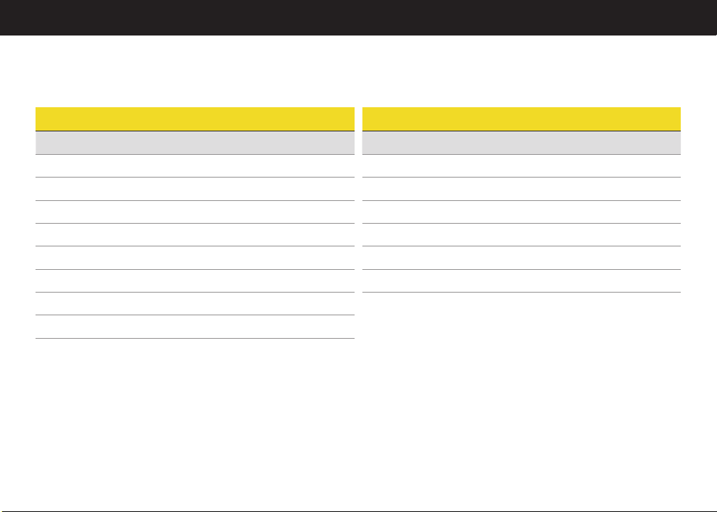
Performance Review
INPUT
PARAMETER MIN MAX UNIT
Input Range 1 –500 500 mV/V nom.
Input Range 2 –12 12 VDC
Input Range 3 0 30 mA
OUTPUT
PARAMETER MIN MAX UNIT
Analog Voltage 0 5 VDC
–5 5 VDC
Analog Current 0 20 mA
420mA
025mA
525mA
20
POWER ADAPTER
PARAMETER MIN MAX
Input 90–264 VAC 0.5 A 50/60 Hz
Output 12 VDC 1A
Page 21

Specifi cations
POWER REQUIREMENT
• Power Supply Adapter: 12 VDC/1 A
SOLID STATE RELAYS
• Part Number: G3VM-2F
• Application: Alarm Relay 1, 2
• Maximum Output Voltage: 250V (AC or DC)
• Maximum Output Current: 120 mA
Note: Internally limited and protected to 110V/100 mA
RESPONSE TIMES
• Conversion capture rate: every sample
• Peak capture rate: every sample
• Valley capture rate: every sample
• Conversion display update rate: 5 times per second
• Peak display update rate: 5 times per second
• Valley display update rate: 5 times per second
PASSWORDS
• Default Password: 0000000
• Alternative Password: Device’s Serial Number
PHYSICAL PROPERTIES
• Instrument Weight: 1.9 lbs. (862g) without mounting
bracket
• Dimensions: 3.8”(W) × 3.8”(L) × 6.5”(D)
BANDWIDTH
The digital output bandwidth has been specifi ed as SPS/4.
The analog output bandwidth has been specifi ed as SPS/4 for
sampling rates less than 1200 SPS and has been specifi ed as
SPS/5 for sampling rates more than 1200 SPS if:
1. ASCII stream output is deactivated
2. IPM650 is not connected to computer
3. All relays are disabled
4. Display is in menu mode (Peak, Valley, Tracking, and data
display are main display mode)
21
Page 22

Notes
22
Page 23

Notes
23
Page 24

10 Thomas, Irvine, CA 92618 USA
Tel: (949) 465-0900
Fax: (949) 465-0905
www.futek.com
 Loading...