


10 Thomas, Irvine, CA 92618 USA
Tel: (949) 465-0900
Fax: (949) 465-0905
Toll Free: (800) 23 FUTEK
IHH500 Product Manual

10 Thomas, Irvine, CA 92618 USA
Tel: (949) 465-0900
Fax: (949) 465-0905
Toll Free: (800) 23 FUTEK
Table of Contents
1 |
Receiving & Unpacking................................................................................................................................ |
- 5 - |
||||
|
1.1 |
Unpacking ................................................................................................................................................. |
- 5 - |
|||
|
1.2 |
Storage........................................................................................................................................................ |
|
|
- 5 - |
|
|
1.3 |
Accessories Supplied ............................................................................................................................... |
- 5 - |
|||
|
1.4 |
Optional Accessories................................................................................................................................ |
- 5 - |
|||
2 |
Safety Considerations & Care for Your Device ........................................................................................ |
- 6 - |
||||
3 |
Important Information for IHH500 ............................................................................................................ |
- 7 - |
||||
|
3.1 |
Performance .............................................................................................................................................. |
- 7 - |
|||
|
3.2 |
Product Introduction................................................................................................................................ |
- 7 - |
|||
4 |
Connector & Wiring Diagram ..................................................................................................................... |
- 9 - |
||||
5 |
Features......................................................................................................................................................... |
|
|
- 10 - |
||
|
5.1 |
IHH500 Overview .................................................................................................................................. |
- 10 - |
|||
|
5.2 |
IHH500 Structure.................................................................................................................................... |
- 14 - |
|||
|
5.3 |
Main Display ........................................................................................................................................... |
- 15 - |
|||
6 |
Main Menu Overview................................................................................................................................. |
- 23 - |
||||
|
6.1 |
Sensor Profile .......................................................................................................................................... |
- 26 - |
|||
|
6.1.1 |
Existing Channels ......................................................................................................................... |
- 27 - |
|||
|
6.1.2 |
View Channel ................................................................................................................................ |
- 28 - |
|||
|
6.1.3 |
New Channel ................................................................................................................................. |
- 29 - |
|||
|
|
6.1.3.1 |
|
Sensor Configuration............................................................................................................... |
- 31 - |
|
|
|
6.1.3.2 |
|
Direction .................................................................................................................................... |
- 32 - |
|
|
|
6.1.3.3 |
|
Unit selection ............................................................................................................................ |
- 33 - |
|
|
|
6.1.3.3.1 |
|
Force (MASS) .................................................................................................................... |
- 34 - |
|
|
|
6.1.3.3.2 |
|
Torque ................................................................................................................................ |
- 35 - |
|
|
|
6.1.3.3.3 |
|
Pressure.............................................................................................................................. |
- 36 - |
|
|
|
6.1.3.3.4 |
|
Displacement .................................................................................................................... |
- 37 - |
|
|
|
6.1.3.3.5 |
|
mV/V .................................................................................................................................. |
- 38 - |
|
|
|
6.1.3.4 |
|
Sensor Capacity ........................................................................................................................ |
- 39 - |
|
|
|
6.1.3.5 |
|
Sensitivity (+) ............................................................................................................................ |
- 40 - |
|
|
|
6.1.3.6 Sensitivity (-) ............................................................................................................................. |
- 41 - |
|||
|
|
6.1.3.7 |
|
Calibration................................................................................................................................. |
- 43 - |
|
|
|
6.1.3.7.1 |
|
Zero Load (+)..................................................................................................................... |
- 43 - |
|
|
|
6.1.3.7.2 |
|
Full Scale (+) ...................................................................................................................... |
- 44 - |
|
|
|
6.1.3.7.3 |
|
Zero Load (-) ..................................................................................................................... |
- 44 - |
|
|
|
6.1.3.7.4 |
|
Full Scale (-)....................................................................................................................... |
- 44 - |
|
|
|
6.1.3.8 |
|
Pulse per rotation ..................................................................................................................... |
- 45 - |
|
|
|
6.1.3.9 |
|
Serial number............................................................................................................................ |
- 46 - |
|
|
|
6.1.3.10 |
|
Limit & THD ........................................................................................................................ |
- 47 - |
|
|
|
6.1.3.10.1 |
First Peak THD ................................................................................................................. |
- 48 - |
||
|
|
6.1.3.10.2 |
First Valley THD............................................................................................................... |
- 49 - |
||
|
|
6.1.3.10.3 |
MIN/MAX Differentiation .............................................................................................. |
- 51 - |
||
|
|
|
|
|
EM1001-B |
|
|
|
|
|
|
- 2 - |
|

|
|
|
|
10 Thomas, Irvine, CA 92618 USA |
|
|
|
|
Tel: (949) 465-0900 |
|
|
|
|
Fax: (949) 465-0905 |
|
|
|
|
Toll Free: (800) 23 FUTEK |
|
|
|
|
|
|
6.1.3.10.4 |
Alarm Limit High............................................................................................................. |
- 53 - |
|
|
6.1.3.10.5 |
Alarm Limit Low.............................................................................................................. |
- 54 - |
|
|
6.1.3.10.6 |
Auto Reset Timer.............................................................................................................. |
- 56 - |
|
6.1.4 |
Edit Channel .................................................................................................................................. |
- 57 - |
||
|
6.1.4.1 |
Sensor Configuration............................................................................................................... |
- 59 - |
|
|
6.1.4.2 |
Direction .................................................................................................................................... |
- 59 - |
|
|
6.1.4.3 |
Unit selection ............................................................................................................................ |
- 59 - |
|
|
6.1.4.3.1 |
Force (MASS) .................................................................................................................... |
- 59 - |
|
|
6.1.4.3.2 |
Torque ................................................................................................................................ |
- 59 - |
|
|
6.1.4.3.3 |
Pressure.............................................................................................................................. |
- 59 - |
|
|
6.1.4.3.4 |
Displacement .................................................................................................................... |
- 59 - |
|
|
6.1.4.3.5 |
mV/V .................................................................................................................................. |
- 59 - |
|
|
6.1.4.4 |
Sensor Capacity ........................................................................................................................ |
- 59 - |
|
|
6.1.4.5 |
Sensitivity (+) ............................................................................................................................ |
- 59 - |
|
|
6.1.4.6 Sensitivity (-) ............................................................................................................................. |
- 59 - |
||
|
6.1.4.7 |
Calibration................................................................................................................................. |
- 59 - |
|
|
6.1.4.7.1 |
Zero Load (+)..................................................................................................................... |
- 59 - |
|
|
6.1.4.7.2 |
Full Scale (+) ...................................................................................................................... |
- 59 - |
|
|
6.1.4.7.3 |
Zero Load (-) ..................................................................................................................... |
- 60 - |
|
|
6.1.4.7.4 |
Full Scale (-)....................................................................................................................... |
- 60 - |
|
|
6.1.4.8 |
Pulse per rotation ..................................................................................................................... |
- 60 - |
|
|
6.1.4.9 |
Serial number............................................................................................................................ |
- 60 - |
|
|
6.1.4.10 |
Limit & THD ........................................................................................................................ |
- 60 - |
|
|
6.1.4.10.1 |
First Peak (THD)............................................................................................................... |
- 60 - |
|
|
6.1.4.10.2 |
First Valley (THD)............................................................................................................ |
- 60 - |
|
|
6.1.4.10.3 |
MIN/MAX Differentiation .............................................................................................. |
- 60 - |
|
|
6.1.4.10.4 |
Alarm Limit High............................................................................................................. |
- 60 - |
|
|
6.1.4.10.5 |
Alarm Limit Low.............................................................................................................. |
- 60 - |
|
|
6.1.4.10.6 |
Auto Reset Timer.............................................................................................................. |
- 60 - |
|
6.1.5 |
Save Changes................................................................................................................................. |
- 61 - |
||
6.1.6 |
Delete Channel .............................................................................................................................. |
- 63 - |
||
6.2 |
System Setting ......................................................................................................................................... |
- 66 - |
||
6.2.1 |
Digit Select ..................................................................................................................................... |
- 67 - |
||
6.2.2 |
Channel Select ............................................................................................................................... |
- 68 - |
||
6.2.3 |
Moving Average ........................................................................................................................... |
- 69 - |
||
6.2.4 |
Sampling Rate................................................................................................................................ |
- 71 - |
||
6.2.5 |
Peak/ Valley ................................................................................................................................... |
- 72 - |
||
6.2.6 |
Auto Reset ...................................................................................................................................... |
- 74 - |
||
6.2.7 |
Alarm Configuration .................................................................................................................... |
- 75 - |
||
6.2.8 |
Alarm Activity............................................................................................................................... |
- 76 - |
||
6.3 |
Data Logging........................................................................................................................................... |
- 77 - |
||
6.3.1 |
Logging Rate.................................................................................................................................. |
- 78 - |
||
6.3.2 |
Duration (SEC) .............................................................................................................................. |
- 79 - |
||
6.3.3 |
Action.............................................................................................................................................. |
- 81 - |
||
|
|
|
|
EM1001-B |
|
|
|
|
- 3 - |

10 Thomas, Irvine, CA 92618 USA
Tel: (949) 465-0900
Fax: (949) 465-0905
Toll Free: (800) 23 FUTEK
|
6.4 |
Output Configuration ............................................................................................................................ |
- 83 - |
|
|
6.4.1 |
Digital ASCII.................................................................................................................................. |
- 84 - |
|
|
6.4.2 |
Alarm Relay 1 ................................................................................................................................ |
- 85 - |
|
|
6.4.3 |
Alarm Relay 2 ................................................................................................................................ |
- 86 - |
|
|
6.4.4 |
Voltage Configuration.................................................................................................................. |
- 87 - |
|
|
6.4.5 |
Current Value ................................................................................................................................ |
- 88 - |
|
|
6.4.6 |
Current Configuration ................................................................................................................. |
- 89 - |
|
|
6.5 |
Interfaces.................................................................................................................................................. |
- 90 - |
|
|
6.5.1 |
USB Output.................................................................................................................................... |
- 91 - |
|
|
6.5.2 |
ASCII output.................................................................................................................................. |
- 92 - |
|
|
6.5.3 |
Relay 1 Output .............................................................................................................................. |
- 93 - |
|
|
6.5.4 |
Relay 2 Output .............................................................................................................................. |
- 94 - |
|
|
6.5.5 |
Voltage Output.............................................................................................................................. |
- 95 - |
|
|
6.5.6 |
Current Output ............................................................................................................................. |
- 96 - |
|
|
6.5.7 |
Power Output ................................................................................................................................ |
- 97 - |
|
|
6.5.8 |
Bridge Input................................................................................................................................... |
- 98 - |
|
|
6.5.9 |
Voltage Input ................................................................................................................................. |
- 99 - |
|
|
6.5.10 Current Input............................................................................................................................... |
- 100 - |
||
|
6.5.11 Pulse Input (This feature is available in Elite Version only) ................................................ |
- 102 - |
||
|
6.6 |
LCD Setting ........................................................................................................................................... |
- 103 - |
|
|
6.6.1 |
Contrast ........................................................................................................................................ |
- 104 - |
|
|
6.6.2 |
Brightness..................................................................................................................................... |
- 105 - |
|
|
6.6.3 |
Auto LCD off ............................................................................................................................... |
- 106 - |
|
|
6.7 |
Lock Settings ......................................................................................................................................... |
- 107 - |
|
|
6.7.1 |
Lockout Profile ............................................................................................................................ |
- 108 - |
|
|
6.7.2 |
Unlock profile.............................................................................................................................. |
- 109 - |
|
|
6.7.3 |
Change Password ....................................................................................................................... |
- 110 - |
|
|
6.8 |
TEDS Data.............................................................................................................................................. |
- 112 - |
|
|
6.8.1 |
TEDS Device ................................................................................................................................ |
- 113 - |
|
|
6.8.2 |
TEDS Page................................................................................................................................... |
- 114 - |
|
|
6.8.3 |
Load Data ..................................................................................................................................... |
- 115 - |
|
|
6.8.4 |
Auto Detection ............................................................................................................................ |
- 116 - |
|
|
6.9 |
Diagnostic .............................................................................................................................................. |
- 117 - |
|
|
6.9.1 |
Internal or External..................................................................................................................... |
- 118 - |
|
7 |
Appendix A (List of Probable Errors) .................................................................................................... |
- 119 - |
||
8 |
Appendix B (List of Messages)................................................................................................................ |
- 120 - |
||
9 |
Appendix C (Device Specifications) ....................................................................................................... |
- 122 - |
||
10 Appendix D TEDS IEEE 1451.4 Introduction........................................................................................ |
- 125 - |
|||
|
10.1 |
|
What is TEDS?.................................................................................................................................. |
- 125 - |
|
10.2 |
|
Basic Concept ................................................................................................................................... |
- 125 - |
|
10.3 |
|
How it works.................................................................................................................................... |
- 125 - |
11 Appendix E (System Performance) ........................................................................................................ |
- 126 - |
|||
EM1001-B - 4 -

10 Thomas, Irvine, CA 92618 USA
Tel: (949) 465-0900
Fax: (949) 465-0905
Toll Free: (800) 23 FUTEK
1 Receiving & Unpacking
1.1 Unpacking
Check all parts to ensure no damage was done during transit. If you suspect that your product is damaged, contact FUTEK at futek@futek.com for immediate support.
1.2 Storage
If the device is to be stored for a prolonged period, take the following safety precautions:
The storage temperature should be between 0°C and +70°C (32°F to 158°F).
Cover all connectors with dust protection caps.
Store in a dry environment.
If possible, store the instrument in its original packaging when not in use.
1.3Accessories Supplied
Battery charger with US plugs (2 pin connector)
Dust protection caps
1.4Optional Accessories
|
USB Cable |
(4 pin connector) |
|
Output Cable |
(8 pin connector) |
|
Sensor Cable |
(12 pin connector) |
Caution
FUTEK is not responsible for any damage or injury caused by misuse, misunderstanding, or abuse of this product.
EM1001-B - 5 -

10 Thomas, Irvine, CA 92618 USA
Tel: (949) 465-0900
Fax: (949) 465-0905
Toll Free: (800) 23 FUTEK
2Safety Considerations & Care for Your Device
Do not disassemble for modifications or repair
Be sure to disconnect the power cable and turn the device off when connecting or disconnecting any of the connectors
Do not operate the device in the following environments:
o Direct sunlight
oWhere the product will be splashed with water, oil, and chemicals
Do not throw, drop, or scratch with any sharp objects
In order to extend the built-in lithium battery life the intelligent battery charger circuit has different curves:
oFast charge: after 2 hours the battery will be charged around 60%
o Normal charge: It takes about 6-7 hours to charge the battery around 90%
oSlow charge: it takes about 10 hours for fully charging the battery
It is recommended to use the slow charge at least once a week
Always use the FUTEK supplied charger to charge the battery
Use the dust protection caps to cover the connectors when you are not using the device.
EM1001-B - 6 -

10 Thomas, Irvine, CA 92618 USA
Tel: (949) 465-0900
Fax: (949) 465-0905
Toll Free: (800) 23 FUTEK
3 Important Information for IHH500
3.1 Performance
The IHH500 is a microcontroller based digital handheld instrument that monitors the activity of a vast range of sensors. This includes Wheatstone bridge strain gauge and amplified output Torque/ Force/ Pressure/ Displacement sensors. All of the measurements are based on a high accuracy, low noise, 24 bit resolution Analog to Digital Converter with a non-linearity of 0.001% and a temperature coefficient factor of less than 5 PPM (zero and span drift). All analog components not only those ones that provide the requirements for ADC such as reference voltage but also the ones which are employed for analog output, excitation voltage and input/output buffers are low noise, low distortion, low temperature coefficient, and high precision/accuracy parts. The combination of these components, along with a high speed microcontroller integrated with a precision DAC controller has provided a high accuracy instrument, which is able to measure the activity of a 2 mV/V sensor with up to a 500,000 count (total) noise free base! The high precision DAC controller has been exploited to provide a ± 5 V voltage output with 100 μV resolution and/or (0-25mA) current output with a 0.5 μA resolution. A wide range of bridge resistances and input/output impedances of external instruments can be applied to this device without any lack of performance.
The IHH500 accepts amplified Voltage input (± 12 VDC), Current input (up to 30mA), Bridge input (up to 500 mV/V), and Pulse/ TTL input (up to 650,000 pulses per second) and has the capability to provide power to FUTEK rotary torque sensors (24 VDC/ 1 W and 5 VDC/ 0.05 W).
3.2Product Introduction
TEDS IEEE 1451.4 compliant with template 30 for High level voltage output sensors and template 33 for bridge sensors
Ability to interact with TEDS data by using the SENSIT Test and Measurement software
Selectable calibration method including live calibration by applying the actual load or manipulating method by entering the sensitivity
Ability to measure bridge resistance
Automated sensitivity calculation based on calibration value
Dual scaling calculation for bi-directional sensors
Selectable units of measure for Force, Torque or Pressure and Displacement with automatic conversion of units between readings
Selectable sampling rate from 5 samples per second to ultra-fast signal sampling rate of 4800 samples per second in 16 different speeds
Selectable moving average method for software filtering
Peak/ Valley and First Peak/ First Valley functions
Manual and auto peak/valley reset functions
Tare/ Gross functions with indicator
Tracking/Hold functions with indicator
Built-in shunt calibration features with indicator
EM1001-B - 7 -

10 Thomas, Irvine, CA 92618 USA
Tel: (949) 465-0900
Fax: (949) 465-0905
Toll Free: (800) 23 FUTEK
Lockout feature to prevent inadvertent changes
Data logging with up to 21,000 points
Supports USB link port
Built-in load cell excitation voltage
Powered by a rechargeable 3000 mAh lithium-polymer battery for up to 24 hours of operation.
Battery/ life indicator with bar graph and text indicators
Selectable automatic display shutoff for period of inactivity (up to 15 minutes)
Selectable latched or non-latched alarm configuration
ASCII Stream Output
Two independently isolated solid state alarm relays, each able to be disabled or enabled individually, with normally open or closed operations and protected at 110mA/110V
Selectable voltage output as bipolar (± 5 V) or uni-polar (0-5V) with 2.5V offset
Selectable current output as bidirectional and unidirectional
Selectable 0-20mA, 0-25mA, 4-20mA, 5-25mA current output
Selectable alarm configuration (Latched or non-Latched)
Supports Speed (RPM), Angle (Degrees), and Power (W/kW/MW/HP) measurements for rotary torque sensors with encodes
Provides a +5.000 V (±1 mV) excitation voltage to bridge resistances as low as 30 Ohms and as high as 30k Ohms with a limited current to 160 mA
Default channel calibrated to 0-4 mV/V using precision BLH
Back lit 4x16 character LCD with selectable brightness, contrast, and auto shut off
Selectable digit height size (4.7 mm and 12.7mm)
Selectable number of digits to be displayed, excluding the decimal point (3, 4, 5, or 6)
Equipped with the diagnostic mode to measure bridge resistance, sensitivity, internal voltage (Analog and digital), battery and temperature
User friendly navigation menu directs users to enable/disable or select/unselect various features with easy to follow instructions
Ability to store 14+1 sensor profiles including calibration values such as Offset, Full scale, Loading point(s) , Engineering unit , Serial number, Sensor type (Bridge, Voltage , Current, Pulse) , Sensitivity, Alarm limits (High and Low) and all Peak/ Valley (First, Hold, Auto reset) Threshold values
Active channel number indicator
IP66 housing and connectors
Aluminum enclosure
Lead free/ RoHS compliant parts
ESD, EMI, EFT and short circuit protected Input and output which covers the CE approval
Note: IHH500 is available in two versions, Elite and Pro.
EM1001-B - 8 -
10 Thomas, Irvine, CA 92618 USA
Tel: (949) 465-0900
Fax: (949) 465-0905
Toll Free: (800) 23 FUTEK
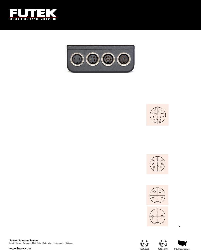
4 Connector & Wiring Diagram
|
Connectors |
|
|
|
|
Description |
|
|
Diagram |
|
|
|
|
|
|
|
|
|
|||
|
|
|
|
|
|
|
(Female Insert) |
|
||
|
|
|
|
|
|
|
|
|
|
|
|
|
|
|
Pin |
Symbol |
Description |
|
|
||
|
|
|
|
A |
+E |
+Excitation |
|
|
||
|
|
|
|
B |
+S |
+Signal |
|
|
||
|
|
|
|
C |
-E |
-Excitation, TEDS return |
|
|
||
|
|
|
|
D |
-S |
-Signal |
|
|
||
|
Sensor |
|
E |
TEDS_IO |
TEDS Data |
|
|
|||
|
|
F |
24_OUT |
24V output |
|
|
|
|||
|
Connections |
|
|
|
||||||
|
|
G |
GND_OUT |
Ground |
|
|
|
|||
|
|
|
|
|
|
|||||
|
|
|
|
H |
5_OUT |
5V Output |
|
|
||
|
|
|
|
J |
-V |
-V from sensor |
|
|
||
|
|
|
|
K |
+V |
+V from sensor |
|
|
||
|
|
|
|
L |
PLEAD |
Leading Pulse from sensor |
|
|
||
|
|
|
|
M |
PLAG |
Lagging Pulse from sensor |
|
|
||
|
|
|
|
Pin |
Symbol |
Description |
|
|
||
|
|
|
1 |
IDAC |
analog current output signal |
|
|
|||
|
|
|
2 |
REFRENCE |
analog voltage output return |
|
|
|||
|
Output |
3 |
+R1 |
solid state relay1 (positive) |
|
|
||||
|
4 |
VDAC |
analog voltage output signal |
|
|
|
||||
|
Connections |
|
|
|||||||
|
5 |
+R2 |
solid state relay2 (positive) |
|
|
|
||||
|
|
|
|
|
||||||
|
|
|
6 |
GND |
analog current output return |
|
|
|||
|
|
|
7 |
-R1 |
solid state relay1 (negative) |
|
|
|||
|
|
|
8 |
-R2 |
solid state relay2 (negative) |
|
|
|||
|
|
|
|
Pin |
Symbol |
|
|
|
|
|
|
USB port |
1 |
VBUS |
|
|
|
|
|
||
|
2 |
-D |
|
|
|
|
|
|||
|
Connections |
|
|
|
|
|
||||
|
3 |
+D |
|
|
|
|
|
|||
|
|
|
|
|
|
|
|
|||
|
|
|
4 |
GND |
|
|
|
|
|
|
|
|
|
|
Pin |
Symbol |
|
|
|
|
|
|
Power |
1 |
12V |
|
|
|
|
|
||
|
2 |
Ground |
|
|
|
|
|
|||
|
Connections |
|
|
|
|
|
||||
|
|
|
|
|
|
|
|
|
||
|
|
|
|
(Note: These pins are not polarity sensitive) |
|
|
||||
|
|
|
|
|
|
|
|
|
|
|
EM1001-B - 9 -

5Features
5.1IHH500 Overview
USB
Power
16x4 Character LCD 
Active Channel
Number 
Battery Indicator 
Menu
Peak/Valley Reset
Shunt Calibration
Verification 
10 Thomas, Irvine, CA 92618 USA
Tel: (949) 465-0900
Fax: (949) 465-0905
Toll Free: (800) 23 FUTEK
Output
 Sensor
Peak Value
Tracking
Valley Value
 Sampling rate
Larger Font
 Display Options
 Tare/ Gross
Unit
Navigation Keys
 Track/ Hold
 Power Key
EM1001-B - 10 -

10 Thomas, Irvine, CA 92618 USA
Tel: (949) 465-0900
Fax: (949) 465-0905
Toll Free: (800) 23 FUTEK
Dust Protection
CapsIP67 
Submersible
Aluminum Enclosure 
Tactile Membrane
 Switches
Adjustable Mount 
Bumpons on back 
FUTEK ADVANCED
SENSOR TECH INC.
IHH500 - ELITE
MADE IN USA
In the welcome message of the Pro version, “PRO” will be displayed.
Above it is shown that the IHH500 is submersible
EM1001-B - 11 -

10 Thomas, Irvine, CA 92618 USA
Tel: (949) 465-0900
Fax: (949) 465-0905
Toll Free: (800) 23 FUTEK
|
Front Panel |
|
|
Function of Button |
|
|
Function of Button in Normal Mode |
|
|
|
|
|
|
|
|||
|
|
|
|
|
|
|||
|
Button |
|
|
in Menu Mode |
|
|
|
|
|
|
|
|
|
|
|
||
|
|
|
|
Enter |
|
|
Displays battery life time |
|
|
|
|
|
|
|
|
|
|
|
|
|
|
|
|
|
Allows the user to toggle between displaying the tare |
|
|
|
|
|
▲Arrow |
|
|
and gross values. This can be used to remove any |
|
|
|
|
|
|
|
|
fixture weights. |
|
|
|
|
|
|
|
|
|
|
|
|
|
|
|
|
|
Allows the user to toggle between two different size |
|
|
|
|
|
|
|
|
fonts. This key selects one of the four different states |
|
|
|
|
|
Back |
|
|
in normal mode and one of the five different states |
|
|
|
|
|
|
|
when a rotary sensor with an encoder is being |
||
|
|
|
|
|
|
|
||
|
|
|
|
|
|
|
monitored. In this case rpm, torque, angle and |
|
|
|
|
|
|
|
|
power will be displayed. |
|
|
|
|
|
◄ Arrow |
|
|
Allows the user to reset the peak/ valley or angle (in |
|
|
|
|
|
|
|
rotary sensors with an encoder) |
||
|
|
|
|
|
|
|
||
|
|
|
|
|
|
|
|
|
|
|
|
|
N/A |
|
|
Start navigation |
|
|
|
|
|
|
|
|
|
|
|
|
|
|
|
|
|
Allows the user to toggle between four groups of |
|
|
|
|
|
► Arrow |
|
|
engineering units (Force, Torque, Pressure, and |
|
|
|
|
|
|
|
|
Displacement) and the standard mV/V.1 |
|
|
|
|
|
|
|
|
|
|
|
|
|
|
|
|
|
Allows the user to shunt the current reading. The |
|
|
|
|
|
Exit |
|
|
device shunts a resistor across the -Excitation and - |
|
|
|
|
|
|
|
|
Signal connections.2 |
|
|
|
|
|
|
|
|
|
|
|
|
|
|
|
|
|
Allows the user to freeze the current reading. HOLD |
|
|
|
|
|
▼ Arrow |
|
|
will be displayed on the LCD showing that it has |
|
|
|
|
|
|
|
been held. When the button or any other key is |
||
|
|
|
|
|
|
|
||
|
|
|
|
|
|
|
pressed, the hold command will be cancelled.2 |
|
|
|
|
|
|
|
|
|
|
|
|
|
|
ON/OFF |
|
|
ON/OFF |
|
|
|
|
|
|
|
|
||
|
|
|
|
|
|
EM1001-B |
||
|
|
|
|
|
- 12 - |
|
||

10 Thomas, Irvine, CA 92618 USA
Tel: (949) 465-0900
Fax: (949) 465-0905
Toll Free: (800) 23 FUTEK
1 Engineering units can only be converted within its own category.
Force (Mass): µg, mg, g, kg, M- tone, dyn, kdyn, Mdyn, N, kN, oz, lbs, klb, ton (US), ton (UK) Torque: g-mm, g-cm, kg-cm, kg-m, N-mm, N-cm, N-m, KN-m, in-oz, in-lb, ft-lb Pressure: Pa, kPa, mbar, bar, MPa, kg/cm², atm (standard atmosphere), mm-HG, in-H2O,
ft-H2O, psi, kpsi
Displacement: mm, cm, dm, m, km, in, ft, yds, mile
2 Pressing SHUNT will disable the HOLD function, but pressing HOLD will not disable the SHUNT function.
Note: When a torque sensor is configured, the HOLD and SHUNT keys are disabled on the main page showing the speed, angle and torque. Using the HOLD and SHUNT keys will prompt a warning message.
EM1001-B - 13 -

10 Thomas, Irvine, CA 92618 USA
Tel: (949) 465-0900
Fax: (949) 465-0905
Toll Free: (800) 23 FUTEK
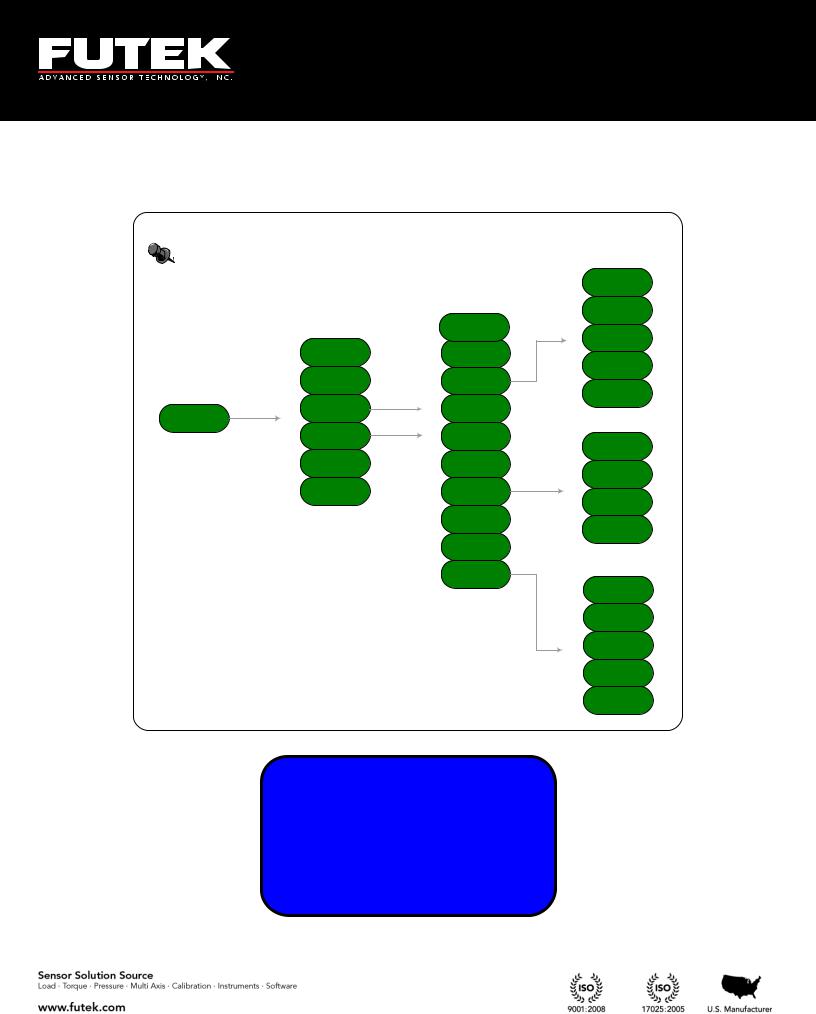
5.2 IHH500 Structure
USB
TEDS
Bridge Input
Pulse Input*
Voltage Input
Current Input
|
|
|
ASCII Output |
|
|
|
|
|
|
|
|
MCPU |
|
|
Current Output |
|
|
||
|
|
|
|
|
|
Voltage Output |
|
|
|
|
|
|
|
|
|
|
|
|
Alarm Relay 1 |
|
|
|
|
|
|
|
|
|
|
|
Alarm Relay 2 |
|
|
|
|
|
|
|
|
|
|
|
|
|
|
|
|
|
|
|
|
|
|
|
|
|
|
|
|
|
|
|
|
|
|
|
|
|
|
|
|
|
|
|
|
|
|
|
|
|
|
Key Pad |
|
|
|
|
Hardware |
|
|
|
|
Display |
|||
|
|
|
|
|
|
|
|
||||||
|
|
|
|
Controller |
|
|
|
|
(LCD) |
||||
|
|
|
|
|
|
|
|
|
|
||||
|
|
|
|
|
|
|
|
|
|
|
|
|
|
|
|
|
|
|
|
|
|
|
|
|
Input Protection |
|
Battery Charger |
|
Power Supply |
|
Output Protection |
||||
|
|
|
|
|
|
|
|
|
|
|
* Available only in Elite Version.
EM1001-B - 14 -

5.3 Main Display
FUTEK ADVANCED SENSOR TECH INC.
IPM650-PRO
MADE IN USA
AUTO CALIBRATION
IN PROGRESS
PLEASE WAIT 11
....
10 Thomas, Irvine, CA 92618 USA
Tel: (949) 465-0900
Fax: (949) 465-0905
Toll Free: (800) 23 FUTEK
Welcome message will be displayed at power on
Auto calibration will be applied when device is turned on. The calibration will minimize any effects of the temperature drift for either zero (offset) or span. During the auto calibration process the key pad is locked out and inaccessible. Brief information about the active channel will be displayed when calibration is complete.
Depending on whether TEDS detect is enabled or not (see section 6.8.4), the following Sensor Profile will be displayed for 10 seconds: TEDS enabled (left), TEDS disabled (right).
TEMPLATE |
33 |
CHANNEL |
01 |
SERIAL |
123456 |
SERIAL |
1 |
20.0000 |
LBS |
SENSOR |
BRIDGE |
1.98765 |
mV/V |
+2.00000 |
mV/V |
EM1001-B - 15 -

10 Thomas, Irvine, CA 92618 USA
Tel: (949) 465-0900
Fax: (949) 465-0905
Toll Free: (800) 23 FUTEK
After 10 seconds the following message will be displayed.
+2.00001 Peak
+2.00000 mV/V
+1.99999 Valley
01 Gross 5 SPS
EM1001-B - 16 -

10 Thomas, Irvine, CA 92618 USA
Tel: (949) 465-0900
Fax: (949) 465-0905
Toll Free: (800) 23 FUTEK
Pressing the display key will change the reading to a larger font. Pressing it again will switch between modes while still in the large font. The tare and gross modes can also be used while in the larger font mode.
PK |
PK |
+2.00001
01 GROSS |
mV/V |
TR
+2.00000
01 GROSS |
mV/V |
VY
+1.99999
01 GROSS |
mV/V |
+2.0000 |
Peak |
+2.00000 |
mV/V |
+1.99999 |
Valley |
01 Gross |
5SPS |
+0.00001
01 TARE |
mV/V |
TR
+0.00000
01 TARE |
mV/V |
VY
-0.00001
01 TARE |
mV/V |
After displaying the Valley, the next change will direct you to the main page again.
EM1001-B - 17 -

10 Thomas, Irvine, CA 92618 USA
Tel: (949) 465-0900
Fax: (949) 465-0905
Toll Free: (800) 23 FUTEK
For rotary torque sensors, the following screen will be displayed before returning to the main screen.
NOTE: To monitor Torque, Speed, Angle, and Power on the SENSIT Test and Measurement software during live graphing, the screen of IHH500 should be changed by pressing the “DISPLAY” key. The following screen will be displayed:
+60000 RPM
+400 N-m
+1800 DEG
+2513.27 KW
If an incorrect unit (other than torque) has been selected for a rotary torque sensor, an error message will be displayed on the last row.
+60000 RPM
+400 N-m
+1800 DEG
INVALID UNIT
Note: When a torque sensor is configured, the HOLD and SHUNT keys are disabled on the main page showing the speed, angle and torque. Using the HOLD and SHUNT keys will prompt a warning message.
EM1001-B - 18 -

10 Thomas, Irvine, CA 92618 USA
Tel: (949) 465-0900
Fax: (949) 465-0905
Toll Free: (800) 23 FUTEK
The shunt key can be pressed any time after the device has been calibrated and a new sensor profile has been loaded. The simulated value is to be used as a calibration reference. SHUNT will blink on the display when enabled.
+3.03461 Peak
+3.03460 mV/V
+1.59484 Valley
01 Gross SHUNT
When both SHUNT and HOLD are active on the last row, the display will switch between blinking SHUNT and blinking HOLD.
EM1001-B - 19 -

10 Thomas, Irvine, CA 92618 USA
Tel: (949) 465-0900
Fax: (949) 465-0905
Toll Free: (800) 23 FUTEK
ĄĆĆĆĆĆĆĆĆĆĆĂ
ćĆĆĆĆĆĆĆĆĆĆĆĆ
ąĆĆĆĆĆĆĆĆĆĆă
CHARGING: 100%
ĄĆĆĆĆĆĆĆĆĆĆĂ ćĆĆĆĆĆĆĆĆĆĆĆĆ
ąĆĆĆĆĆĆĆĆĆĆă
CHARGING: 28%
BATTERY LOW!
CONNECT THE
BATTERY CHARGER TO THE DEVICE
BATTERY FULL! YOU CAN UNPLUG BATTERY CHARGER FROM THE DEVICE
The Battery key will allow you to view the battery life time.
Pressing the battery button while the charger is plugged in will display a battery charging screen.
Whenever the battery level drops below 6.5V, a warning message will be displayed.
Whenever the battery level exceeds 8V and the charger is connected, a warning message will be displayed.
EM1001-B - 20 -
10 Thomas, Irvine, CA 92618 USA
Tel: (949) 465-0900
Fax: (949) 465-0905
Toll Free: (800) 23 FUTEK
There are two pulse signals, P1 and P2, which are used to indicate speed, angle, power, and the direction of rotation. These pulses are 90 degrees out of phase, and depending on which pulse is leading or lagging or how many pulses are present in a certain time frame, the IHH500 can calculate these values.
Leading, TTL
Lagging, TTL
Calculation of Power:
Power is calculated by using the following formula:
T 2 RPM P T N
60000
Where:
P:mechanical power in kW
T: torque in N-m
RPM: speed in rev / min
Calculating the Power Units:
If the g-mm, g-cm, g-m or N-mm units have been defined, the mechanical power is automatically calculated in W
If the kg-cm, kg-m, or N-m units have been defined, the mechanical power is automatically calculated in kW
If the kN-m unit has been defined, the mechanical power is automatically calculated in MW
If the In-Ib, oz-in or ft-Ib units have been defined, the mechanical power is automatically calculated in HP
Direction of Rotation:
Since there are two pulses, a direction of rotation (CW or CCW) can be defined depending on which pulse is leading.
EM1001-B - 21 -

10 Thomas, Irvine, CA 92618 USA
Tel: (949) 465-0900
Fax: (949) 465-0905
Toll Free: (800) 23 FUTEK
Calculation of Speed:
The input frequency that can be evaluated for recording the speed is used in defining the speed. The input speed based on the pulses per rotation can be calculated as follows:
N f 60
PPR
Where:
N: Speed (RPM)
f:Frequency
PPR: User-defined pulses per rotation (selectable up to 9999)
Angle calculation:
After calculating the Angle will be computed based on pulse per rotation.
RPM PPR
60
Where:
RPM: Revolution per Minute PPR: Pulse per Rotation
α: Angle
Note: the resolution of Angle calculation is 1 degree.
EM1001-B - 22 -

10 Thomas, Irvine, CA 92618 USA
Tel: (949) 465-0900
Fax: (949) 465-0905
Toll Free: (800) 23 FUTEK
6 |
Main Menu Overview |
|
|
|
|
|
|
|
|
|
|
|
|||||||||||
|
|
|
|
|
|
|
|
|
|
|
|
|
|
|
|
|
|
|
|
|
|
|
|
|
|
|
|
|
|
|
|
|
|
|
|
|
|
EXIS TING CH(S ) |
|
S ENS OR CONFIG |
|
|
|
|
FORCE (MAS S ) |
||
|
|
|
|
|
|
|
|
|
|
|
|
|
|
|
|
|
|
|
|
|
|
|
|
|
|
|
|
|
|
|
|
|
|
|
|
|
|
VIEW CHANNEL |
|
|
|
DIRECTION |
|
|
|
|
TORQUE |
|
|
|
|
|
|
|
|
|
|
|
|
|
|
|
|
|
|
|
|
|
|
|
|
|
|
|
|
|
|
|
|
|
|
|
|
|
|
NEW CHANNEL |
|
|
|
UNIT S ELECTION |
|
|
|
|
PRES S URE |
|
|
|
|
|
|
|
|
|
|
|
|
|
|
|
|
|
|
|
|
|
|||
|
|
|
|
|
|
|
|
|
|
|
|
|
|
|
|
|
|
|
|
|
|
|
|
|
|
|
|
|
|
|
|
|
|
|
|
|
|
EDIT CHANNEL |
|
|
|
S ENS OR CAPACITY |
|
|
|
|
DIS PLACEMENT |
|
|
|
|
|
|
|
|
|
|
|
|
|
|
|
|
|
|
|
|
|
|||
|
|
|
|
|
|
|
|
|
|
|
|
|
|
|
|
|
|
|
|
|
|
|
|
|
|
|
|
|
|
|
|
|
|
|
|
|
|
S AVE CHANGES |
|
|
|
S ENS ITIVITY (+) |
|
|
|
|
mV/V |
|
|
|
|
|
|
|
|
|
|
|
|
|
|
|
|
|
|
|
|
|
|
|
|
|
|
|
|
|
|
|
|
|
|
|
|
|
|
DELETE CHANNEL |
|
|
|
S ENS ITIVITY (-) |
|
|
|
|
|
|
|
|
|
|
|
|
|
|
|
|
|
|
|
|
|
|
|
CALIBRATION |
|
|
|
|
ZERO LOAD (+) |
|
|
|
|
|
|
|
|
|
|
|
|
|
|
|
|
|
|
|
|
|
|
|
|
|
|
|
|
|
|
|
|
|
|
|
|
|
|
DIGITS S ELECT |
|
|
|
PULS E PER ROTATION |
|
|
|
|
FULLS CALE (+) |
|
|
|
|
|
|
|
|
|
|
|
|
|
|
|
|
|
|
|
|
|
|
|
|
|
|
|
|
|
|
|
|
|
|
|
|
|
|
CHANNEL S ELECT |
|
|
|
|
|
|
|
ZERO LOAD (-) |
|
|
|
|
|
|
|
|
|
|
|
|
|
|
|
|
|
|
|
|
|
|
|
||
|
|
|
|
|
|
|
|
|
|
|
|
|
|
|
|
|
S ERIAL NUMBER |
|
|
|
|
||
|
|
|
|
|
|
|
|
|
|
|
|
|
|
|
|
|
|
|
|
|
|
|
|
|
|
|
|
|
|
|
|
|
|
|
|
|
|
MOVING AVERAGE |
|
|
|
|
|
|
|
|
FULLS CALE (-) |
|
|
|
|
|
|
|
|
|
|
|
|
|
|
|
LIMIT & THD |
|
|
|
|
||||
|
|
|
|
|
|
|
|
|
|
|
|
|
|
|
|
|
|
|
|
|
|
|
|
|
|
|
|
|
|
|
|
|
|
|
|
|
|
S AMPLING RATE |
|
|
|
|
|
|
|
|
|
|
|
|
|
|
|
|
|
|
|
|
|
|
|
|
|
|
|
|
|
|
|||
|
|
S ENS OR PROFILE |
|
|
|
|
|
|
|
|
|
|
|
|
|
|
|
|
|
|
|
FIRS T PEAK (THD) |
|
|
|
|
|
|
|
|
|
|
|
|
|
|
PEAK / VALLEY |
|
|
|
|
|
|
|
|
||
|
|
|
|
|
|
|
|
|
|
|
|
|
|
|
|
|
|
||||||
|
|
|
|
|
|
|
|
|
|
|
|
|
|
|
|
|
|
|
|
|
|
|
|
|
|
|
|
|
|
|
|
|
|
|
|
|
|
|
|
|
|
|
|
|
|
|
FIRS T VALLEY (THD) |
|
|
|
|
|
|
|
|
|
|
|
|
|
|
AUTO RES ET |
|
|
|
|
|
|
|
|
|
|
|
S YS TEM S ETTING |
|
|
|
|
|
|
|
|
|
|
|
|
|
|
|
|
|
|
|
|
|
|
|
|
|
|
|
|
|
|
|
|
|
|
|
|
|
|
|
|
MIN/MAX DIFF |
||||
|
|
|
|
|
|
|
|
|
|
|
|
|
ALARM CONFIG |
|
|
|
|
|
|
|
|
||
|
|
|
|
|
|
|
|
|
|
|
|
|
|
|
|
|
|
|
|
|
|
||
|
|
|
|
|
|
|
|
|
|
|
|
|
|
|
|
|
|
|
|
|
|||
|
|
|
|
|
|
|
|
|
|
|
|
|
|
|
|
|
|
|
ALARM LIMIT |
||||
|
|
|
|
|
|
|
|
|
|
|
|
|
|
|
|
|
|
|
|
|
|
|
|
|
|
DATA LOGGING |
|
|
|
|
|
|
|
|
|
|
|
ALARM ACTIVITY |
|
|
|
|
|
|
|
|
HIGH |
|
|
|
|
|
|
|
|
|
|
|
|
|
|
||||||||||
|
|
|
|
|
|
|
|
ALARM LIMIT |
|||||||||||||||
|
|
|
|
|
|
|
|
|
|
|
|
|
|
|
|
|
|
|
|
|
|
|
|
|
|
|
|
|
|
|
|
|
|
|
|
|
|
|
|
|
|
|
|
|
|
|
|
|
|
|
|
|
|
|
|
|
|
|
|
|
|
|
|
|
|
|
|
|
|
|
LOW |
|
|
|
|
|
|
|
|
|
|
|
|
|
|
|
|
|
|
|
|
|
|
|
|
|
|
|
|
|
|
|
|
|
|
|
|
|
|
|
|
|
|
|
|
|
|
|
AUTO RES ET TIMER |
|
|
OUTPUT CONFIG |
|
|
|
|
|
|
|
|
|
|
|
LOGGING RATE |
|
|
|
|
|
|
|
|
(S EC) |
|
|
|
|
|
|
|
|
|
|
|
|
|
|
DURATION(S EC) |
|
|
|
|
|
|
|
|
|
|
|
|
|
|
|
|
|
|
|
|
|
|
|
|
|
|
|
|
|
|
|
|
|
|
|
INTERFACES |
|
|
|
|
|
|
|
|
|
|
|
|
|
|
|
|
|
|
|
|
|
|
|
|
|
|
|
|
|
|
|
|
|
|
ACTION |
|
|
|
|
|
|
|
|
|
|
|
|
|
|
|
|
|
|
|
|
|
|
|
|
|
|
|
|
|
|
|
|
|
|
|
|
|
|
|
|
|
|
|
|
|
|
|
|
|
|
|
|
|
|
|
|
|
|
|
|
LCD S ETTING |
|
|
|
|
|
|
|
|
|
|
|
|
|
|
|
|
|
|
|
|
|
|
|
|
|
|
|
|
|
|
|
|
|
DIGITAL AS CII |
|
|
|
|
|
|
|
|
|
||
|
|
|
|
|
|
|
|
|
|
|
|
|
|
|
|
|
|
|
|
|
|
|
|
|
|
|
|
|
|
|
|
|
|
|
|
|
|
|
|
|
|
|
|
|
|
|
|
|
|
|
|
|
|
|
|
|
|
|
|
|
|
ALARM RELAY1 |
|
|
|
|
|
|
|
|
|
|
|
LOCK S ETTING |
|
|
|
|
|
|
|
|
|
|
|
|
|
|
US B OUTPUT |
|
|
|
|
|
|
|
|
|
|
|
|
|
|
|
|
|
|
|
|
|
|
|
|
|
|
|
|
||
|
|
|
|
|
ALARM RELAY2 |
|
|
|
|
|
|
|
|
||||||||||
|
|
|
|
|
|
|
|
|
|
|
|
|
|
|
|
|
AS CII OUTPUT |
|
|
|
|
|
|
|
|
|
|
|
|
|
|
|
|
|
|
|
|
|
|
|
|
|
|
|
|
||
|
|
|
|
|
|
|
|
|
|
|
|
|
|
|
|
|
|
|
|
|
|
|
|
|
|
TEDS DATA |
|
|
|
|
|
|
|
|
|
|
VOLTAGE CONFIG |
|
|
|
|
|
|
|
|
|
|
|
|
|
|
|
|
|
|
|
|
|
|
|
|
|
|
RELAY1 OUTPUT |
|
|
|
|
|
||
|
|
|
|
|
|
|
|
|
|
|
|
|
|
|
|
|
|
|
|
|
|
|
|
|
|
|
|
|
|
|
|
|
|
|
|
|
|
CURRENT VALUE |
|
|
|
|
|
|
|
|
|
|
|
|
|
|
|
|
|
|
|
|
|
|
|
|
|
|
|
|
|
|
|
|
|
|
|
|
|
|
|
|
|
|
|
|
|
|
|
|
|
|
RELAY2 OUTPUT |
|
|
|
|
|
|
|
|
DIAGNOS TIC |
|
|
|
|
|
|
|
|
|
|
|
|
|
|
|
|
|
|
|
|
|
|
|
|
|
|
|
|
|
|
|
|
|
|
CURRENT CONFIG |
|
|
|
|
|
|
|
|
||
|
|
|
|
|
|
|
|
|
|
|
|
|
|
|
|
|
|
|
|
||||
|
|
|
|
|
|
|
|
|
|
|
|
|
VOLTAGE OUTPUT |
|
|
|
|
|
|||||
|
|
|
|
|
|
|
|
|
|
|
|
|
|
|
|
|
|
|
|
|
|
||
|
|
|
|
|
|
|
|
|
|
|
|
|
|
|
|
|
|
|
|
|
|
|
|
|
|
|
|
|
|
|
|
|
|
|
|
|
|
|
|
|
|
|
|
|
|
|
|
|
|
|
|
|
|
|
|
|
|
|
|
|
|
|
|
|
|
|
|
|
|
|
|
|
|
|
|
|
|
|
|
|
|
|
|
|
|
|
|
|
|
CURRENT OUTPUT |
|
|
|
|
|
|
|
|
|
|
|
|
|
|
|
|
|
|
|
CONTRAS T |
|
|
|
|
|
|
|
|
|
|
|
|
|
|
|
|
|
|
|
|
|
|
|
|
|
|
|
|
|
|
|
|
|
|
|
|
|
|
|
|
|
|
|
|
|
|
|
|
|
|
|
POWER OUTPUT |
|
|
|
|
|
|
|
|
|
|
|
|
|
|
|
|
|
|
|
BRIGHTNES S |
|
|
|
|
|
|
|
|
|
|
|
|
|
|
|
|
|
|
|
|
|
|
|
|
|
|
|
|
|
|
|
|
|
|
|
|
|
|
|
|
|
|
|
|
|
|
|
|
|
|
BRIDGE INPUT |
|
|
|
|
|
|
|
|
|
|
|
|
|
|
|
|
|
|
|
|
|
|
|
|
|
|
|
|
|
|
|
|
|
|
|
|
|
|
|
|
|
|
|
|
AUTO LCD OFF |
|
|
|
|
|
|
|
|
|
|
|
|
|
|
|
|
|
|
|
|
|
|
|
|
|
|
|
|
|
|
|
|
|
|
|
|
|
|
|
|
|
|
|
|
|
|
|
|
|
|
VOLTAGE INPUT |
|
|
|
|
|
|
|
|
|
|
|
|
|
|
|
|
|
|
|
|
|
|
|
|
|
|
|
|
|
|
|
|
|
|
|
|
|
|
|
|
|
|
|
|
|
|
|
|
|
|
|
|
|
|
|
|
|
|
|
|
|
|
|
|
|
|
|
|
|
|
|
|
|
|
|
|
|
|
|
|
|
|
|
|
|
|
|
|
|
|
|
|
LOCKOUT PROFILE |
|
|
|
CURRENT INPUT |
|
|
|
|
|
|
|
|
|
|
|
|
|
|
|
|
|
|
|
|
|
|
|
|
|
|
|
|
|
|
|
|
|
|
|
|
|
|
|
|
|
|
|
UNLOCK PROFILE |
|
|
|
PULS E INPUT |
|
|
|
|
|
|
|
|
|
|
|
|
|
|
|
|
|
|
|
|
|
|
|
|
|||||
|
|
|
|
|
|
|
|
|
|
|
|
|
|
CHANGE PAS S WORD |
|
|
|
|
|
|
|
|
|
|
|
|
|
|
|
|
|
|
|
|
|
|
|
|
|
|
|
|
|
|
|
|
|
|
|
|
|
|
|
|
|
|
|
|
|
|
|
|
|
|
|
|
|
|
|
|
|
|
|
|
|
|
|
|
|
|
|
|
|
|
|
TEDS DEVICE |
|
|
|
|
|
|
|
|
|
|
|
|
|
|
|
|
|
|
|
|
|
|
|
|
|
|
|
|
|
|
|
|
|
|
|
|
|
|
|
|
|
|
|
|
|
|
|
TEDS PAGES |
|
|
|
|
|
|
|
|
|
|
|
|
|
|
|
|
|
|
|
|
|
|
|
|
|
|
|
|
|
|
|
|
|
|
|
|
|
|
|
|
|
|
|
|
|
|
|
LOAD DATA |
|
|
|
|
|
|
|
|
|
|
|
|
|
|
|
|
|
|
|
|
|
|
|
|
|
|
|
|
|
|
|
|
|
|
|
|
|
|
|
|
|
|
|
|
|
|
|
AUTO DETECTION |
|
|
|
|
|
|
|
|
|
|
|
|
|
|
|
|
|
|
|
|
|
|
|
|
|
|
|
|
|
|
|
|
|
|
|
|
|
|
|
|
|
|
|
|
|
|
(INTERNAL, EXTERNAL) |
|
|
|
|
|
|
||||
|
|
|
|
|
|
|
|
|
|
|
|
|
|
|
|
|
|
|
|||||
EM1001-B - 23 -

10 Thomas, Irvine, CA 92618 USA
Tel: (949) 465-0900
Fax: (949) 465-0905
Toll Free: (800) 23 FUTEK
Sensor Profile
System setting
Data Logging
Main Menu
Output Config
interfaces
LCD Setting
Lock Setting
TEDS Data
Diagnostic
EM1001-B - 24 -

10 Thomas, Irvine, CA 92618 USA
Tel: (949) 465-0900
Fax: (949) 465-0905
Toll Free: (800) 23 FUTEK
SENSOR PROFILE SYSTEM SETTING ►DATA LOGGING
OUTPUT CONFIG
INTERFACES
LCD SETTING
►LOCK SETTING TEDS DATA
LOCK SETTINGS
TEDS DATA
►DIAGNOSTIC
------------
Press the MENU key to enter the main menu.
Use ▲▼keys to select the desired menu option.
Press ENTER to navigate to the submenu.
The EXIT button can be used at any time to exit any menu or sub menu and return to the display page.
The BACK button can be used at any time to step back from any sub menu.
EM1001-B - 25 -
6.1 Sensor Profile
|
Sensor |
|
Configuration |
ExistingChannel |
Direction |
View Channel |
Unit Selection |
New Channel |
Sensor capacity |
Sensor profile |
|
Edit Channel |
Sensitivity (+) |
Save Changes |
Sensitivity (-) |
Delete Channel |
Calibration |
|
Pulse per |
|
Rotation |
|
Serial Number |
|
Limit & THD |
►SENSOR PROFILE SYSTEM SETTING DATA LOGGING OUTPUT CONFIG
EM1001-B - 26 -
10 Thomas, Irvine, CA 92618 USA
Tel: (949) 465-0900
Fax: (949) 465-0905
Toll Free: (800) 23 FUTEK
Force
Torque
Pressure
Displacement
mV/V
Zero Load (+)
Full Scale (+)
Zero Load (-)
Full Scale (-)
First PK (THD)
First VY (THD)
MIN/MAX Diff
Alarm Limit High
Auto Reset Timer

10 Thomas, Irvine, CA 92618 USA
Tel: (949) 465-0900
Fax: (949) 465-0905
Toll Free: (800) 23 FUTEK
Select “SENSOR PROFILE” from the main menu options and press ENTER. The following options are available: EXISTING CH(S), VIEW CHANNEL, NEW CHANNEL, EDIT CHANNEL, SAVE CHANGESand DELETE CHANNEL.
► EXISTING CH(S) |
► EDIT |
CHANNEL |
VIEW CHANNEL |
SAVE |
CHANGES |
NEW CHANNEL |
DELETE CHANNEL |
|
EDIT CHANNEL |
----------- |
|
6.1.1Existing Channels
Scroll to “EXISTING CH(S)” using the ▲▼ keys and press ENTER to view the different sensor profiles. The IHH500 is able to store up to 15 different sensor profiles.
► EXISTING CH(S) |
01¾ NA |
NA |
NA |
|
VIEW CHANNEL |
NA |
NA |
NA |
NA |
NEW CHANNEL |
NA |
NA |
NA |
NA |
EDIT CHANNEL |
NA |
NA |
NA |
|
The active channel number will be shown with a check mark on the right.
This function is useful to have a quick view of the number of channels (sensor profile) that have been stored in the internal memory and whether they are active or not. The active channel has a check mark next to it. For example, in this specific figure only channel 01 exists and is active.
TEDS activity is shown separately. If TEDS is present it will be shown in the bottom right area. BACK can be pressed at any time to return to other sensor profile options.
01¾ NA NA NA NA NA NA NA NA NA NA NA NA NA NA TD
EM1001-B - 27 -

10 Thomas, Irvine, CA 92618 USA
Tel: (949) 465-0900
Fax: (949) 465-0905
Toll Free: (800) 23 FUTEK
6.1.2View Channel
Scroll to select “VIEW CHANNEL” form the “SENSOR PROFILE” using the▲▼ keys and press ENTER to view: channel number, sensor type, serial number, capacity and engineering unit. If currently more than one channel exists, pressing the arrow ◄►keys on the keypad will cycle through the existing channels.
EXISTING CH(S) |
CHANNEL |
01 |
► VIEW CHANNEL |
SERIAL |
0 |
NEW CHANNEL |
SENSOR |
BRIDGE |
EDIT CHANNEL |
+2.00000 |
mV/V |
EM1001-B - 28 -

10 Thomas, Irvine, CA 92618 USA
Tel: (949) 465-0900
Fax: (949) 465-0905
Toll Free: (800) 23 FUTEK
6.1.3New Channel
Scroll to “NEW CHANNEL” from the “SENSOR PROFILE” using the▲▼ keys and press ENTER. Use the ◄► to select the remaining 2 to 15 channels. Press ENTER to set the data for desired channel.
Note: The first channel is already set as default and will be displayed on the screen if no other channel has been set.
EXISTING CH(S) |
SELECT DESIRED |
VIEW CHANNEL |
CHANNEL NUMBER |
► NEW CHANNEL |
USING ◄,► KEYS |
EDIT CHANNEL |
[02] |
►SENSOR CONFIG DIRECTION
UNIT SELECTION SENSOR CAPACITY
In order to set the new channel data the following steps must be taken exactly in the order in which it is shown on the screen, the ▼key cannot be used to skip the steps. If EXIT is pressed while setting the new channel or editing an existing channel, following warning message will be displayed:
WARNING!
EXIT WITHOUT SAVING PROFILE? <YES> <NO>
EM1001-B - 29 -

10 Thomas, Irvine, CA 92618 USA
Tel: (949) 465-0900
Fax: (949) 465-0905
Toll Free: (800) 23 FUTEK
This function is not available if lockout option is enabled. See section 6.7 for further information how to enable or disable lock settings. If this device is being used for the first time, it has not been locked yet.
If this device is already locked, the following message will appear if “NEW CHANNEL” is selected:
SELECTED FEATURE IS NOT AVAILABLE AT THIS TIME (HIT ENTER/BACK)
EM1001-B - 30 -
 Loading...