

Page 1
Revised July 2006
IPM520
OPERATOR'S MANUAL
10 THOMAS IRVINE , CA 92618
Tel- (949) 465-0900 Fax - (949) 465-0905
Internet: www.futek.com
Page 2

Our recommendations, if any, for those of these products are based on tests
believed to be reliable. The greatest care is exercised in the selection of our raw
materials and in our manufacturing operations. However, since the use of this
product is beyond the control of the manufacturer, no guarantee or warranty,
expressed or implied is made as to such use or effects incidental to such user
handling or possession or the results to be obtained, whether in accordance with
the direction or claimed so to be. The manufacturer expressly disclaims
responsibility therefore. Furthermore, nothing contained herein shall be construed
as a recommendation to use any product in conflict with existing laws and/or
patents covering any material or use.
Warranties or sale, disclaimer thereof and limitations of liability are covered
exclusively by DigiTec's printed warranty statement, for the Enclosed Products.
These instructions do not expand, reduce, modify or alter
Futek's warranty
statement and no warranty or remedy in favor of a customer or any other person
arises out of these instructions.
Call Futek for all your instrumentation and process and control
applications. Application Engineers are available to answer any
questions.
10 Thomas • Irvine, CA 92618
Phone: (949) 465-0900
Fax: (949) 465-0905
Internet: www.futek.com
1
Page 3

Table of Contents
Section Topic Page
Section 1 Introduction and Description
Section 1.1 Product Description 3
Section 1.2 Dimensional Drawings 4
Section 1.3 Exploded View 4
Section 2 Pin Outs and Wiring Diagram
Section 2.1 Main Board and Option Board Connections 5
Section 2.2 Option Board Connections 6
Section 2.2 RS232 connection drawings 8
Section 2.4 Channel 1 Input Connections 10
Section 2.5 Channel 2 Input Connections (3722A Only) 11
Section 3 Operation and Programming
Section 3.1 Front Panel Keys 12
Section 3.2 Setup Mode Key Functions 12
Section 3.3 Run Mode Key Functions 13
Section 3.4 Programming Tips 18
Section 3.5 Enter Setup 19
Section 3.6 Main Programming Branch 21
Section 3.7 Channel Setup Programming Branch 22
Section 3.8 Output Setup Programming Branch 26
Section 3.9 Display Programming Branch 29
Section 3.10 Special Features Programming Branch 29
Section 4 Options 36
Section 5 Specifications 38
Inside Back Cover 3700 Flow Chart
2
Page 4

SECTION 1
INTRODUCTION AND DESCRIPTION
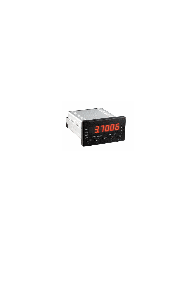
SECTION 1.1: UNIT DESCRIPTION:
The single input and the dual input intelligent process
meters features 5 ½ digit resolution, 6 digit display, high speed, 5 front key
operation and a NEMA 4X, industrialized aluminum case. One Form A relay is
provided standard for use as an Alarm output or shunt cal relay. The
emphasizes the features required in today’s applications, especially scaling of the
meter to display in engineering units. Three methods are provided to scale the
meter: No calculation scale and offset, load calibration and shunt calibration
Stock #'s:
FSH00248- one input channel
FSH00947- two input channels; Options C, H, P, T installed
Options:
"C" 3 Form C Relays
"H" Analog & Excitation Output
"P" Excitation Supplies 10/24 VDC
"T" Serial RS-232C Communication
Ordering Example:
3720A-01CH Single Input with 3 Relays, Analog output,
and Screw Terminals.
IPM500
only.
3
Page 5
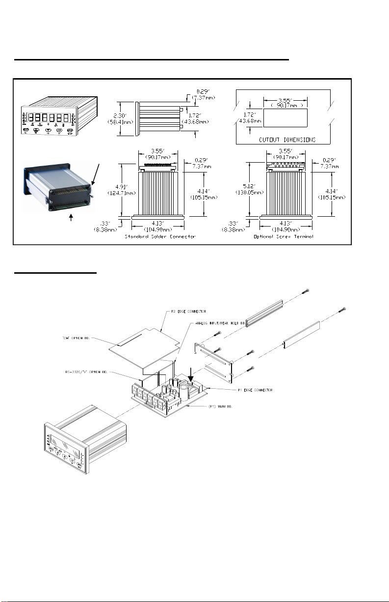
SECTION 1.2: DIMENSIONAL DRAWINGS
P2 (Option Board/Top
Connector)
P1 (Main Board /Bottom
Connector)
SECTION 1.3
FUSE
4
Page 6
SECTION 2
SECTION 2.0 SAFETY SUMMARY
All safety related regulations; local codes and instructions that appear in this
literature or on equipment must be observed to ensure personal safety and to prevent
damage to either the instrument or equipment connected to it. If equipment is used in a
manner not specified by the manufacture, the protection provided by the equipment may be
impaired.
Do not use this unit directly command motors, valves, or other actuators not
equipped with safeguards. To do so can be potentially harmful to persons or equipment in
the event of a fault to the unit.
CAUTION: Read complete CAUTION: Risk of Electric shock
Instructions prior to installation
And operation of the unit.
The unit must be properly grounded. Ground connection is tied to the Main Board “P1”
connector pin C.
Fuse replacement must be performed with power disconnected. Use only the same type
fuse. The fuse must be a TR5 microfuse, Time Lag (T), 1 amp, 250VAC. Fuse location
shown in section 1.3
5
Page 7
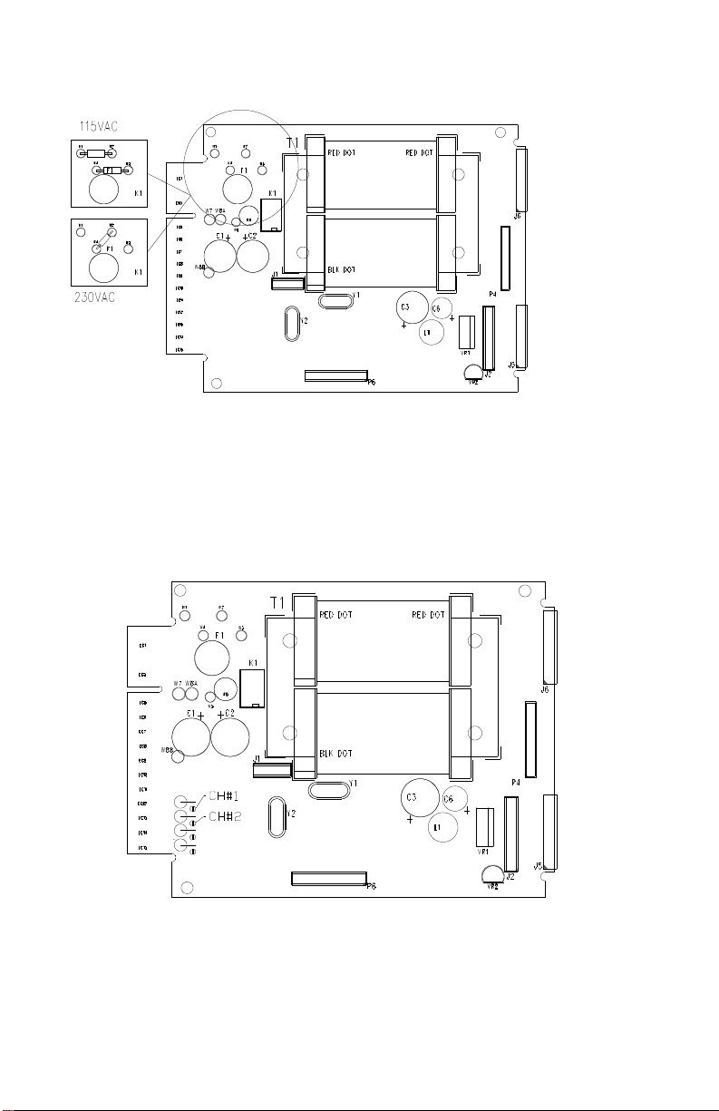
POWER 115 OR 230VAC SELECTION:
configuring the jumpers in the above drawing.
20MA SOLDER JUMPER LOCATION
The IPM500 can be configured to operate on 115VAC or 230VAC by
To select 4-20ma input range solder across solder pads shown above.
6
Page 8
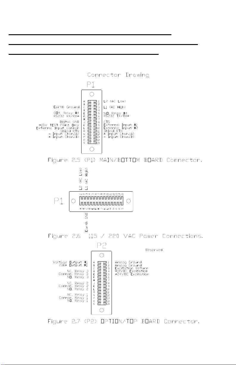
PIN OUTS AND WIRING DIAGRAMS
SECTION 2.1: MAIN BOARD/BOTTOM (P1) AND
OPTION BOARD/TOP (P2) PIN OUTS
7
Page 9
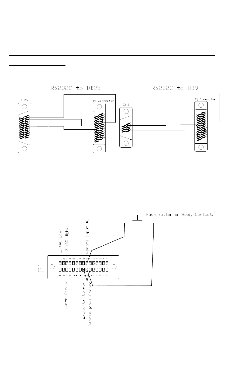
SERIAL RS-232C CONNECTIONS ON P1(MAIN BD)
CONNECTOR
EXAMPLE REMOTE INPUT WIRING
8
Page 10
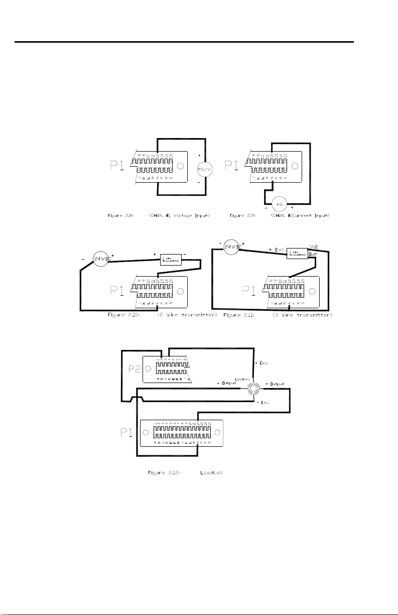
SECTION 2.4: CHANNEL #1 INPUT CONNECTIONS
9
Page 11

LED's
SECTION 3
OPERATION AND PROGRAMMING
SECTION 3.1: FRONT PANEL KEYS
Channel
LED's
Function
The front panel keyboard has two modes of operation - SETUP and RUN
SETUP MODE KEYS
SELECT EXIT ENTER
RUN MODE KEYS
F1 F2 F3 F4 SETUP
Alarm
LED's
Function
Keys
SECTION 3.2: SETUP MODE KEY FUNCTIONS
1. SELECT KEY ( on flow chart indicates to use this key)
• Selects choice of functions within the menu you are setting up.
> Moves you left/right in the program menu.
• When entering numeric data, it allows the selection of digit to be
changed.
> Indicated by digit flashing.
• When selecting decimal point, it moves the decimal point
location.
2. UP ARROW KEY
• When entering numeric data, it increments the current value of
the flashing digit by one with each push.
3. DOWN ARROW KEY
10
Page 12

• When entering numeric data, it decrements the numeric value of
the flashing digit by one with each push.
4. EXIT KEY
• If at a Main branch prompt (CODE, CHAN, OUTPUT, DISPLY
or SPEC), it exits to you back to RUN mode.
• If in a programming branch, it returns you to Main branch
prompt.
NOTE: It does note store data to memory on its return.
ENTER key should be pushed first to store selected entry,
then EXIT key.
5. ENTER KEY ( on flow chart indicates to use this key)
• Enters selected Main program branch.
> Moves you down in the program branch menu.
> Menu steps can be skipped by repeatedly pushing ENTER
key till desired menu step is reached.
• Enters selected choices, numeric data or decimal point, it stores
the value and advances to next step in the program menu.
SECTION 3.3: RUN MODE KEY FUNCTIONS
A. Entering SETUP
Push and hold SETUP key for 4 seconds. Meter will first
display “SET CH” then display “CODE” or flash “SETUP then
display “CHAN”.
• “CODE” is flashed with 00 if a lockout code has been
under the Main program branch heading SPEC, CODE
menu.
> The preset lockout must be entered at this time. If
wrong code is entered or if no code is entered within
20 seconds, meter will return to RUN mode.
> Upon correct lockout code entry, meter enters the
SETUP mode.
> The unmarked yellow LED just above the Down/F4
key will light, indicating you are in the SETUP mode.
• If no lockout code, “SETUP” flashed then “CHAN”
displayed, indicating you have entered the SETUP mode.
11
Page 13

If no key is pressed within 20 seconds, meter will return
to RUN mode.
B. If SETUP key pushed and released meter will enter select
channel program.
• “SET CH” (SET CHANNEL) will be display.
> Push F1 to select Channel 1 for display
> Push F2 to select Channel 2 for display
(3722A only)
> Push F3 to select Channel 3 for display
(3722A only)
C. USER PROGRAMMABLE MENU LOCKOUT.
To enter, push and hold SETUP key, then enter lockout code
“55”. This program allows user to disable/lockout the following
menus from the SETUP program. When the menus are
programmed to be locked, the unit will display “DISABL” when
you try to enter the menu.
NOTE: A code # must be preprogrammed under
SPEC, CODE to get the prompt for the code value.
To disable one or more of the selections add the values from the table and
enter that number. If 0 is entered, all programs under that heading are
enabled.
• “LEVEL1” is flashed with current selected number, valid
values 0-15
0 Don’t Skip any branches
1 Skip all channel programs "CHAN"
2 Skip all output programs "OUTPUT"
4 Skip all display program "DISPLY"
8 Skip all special programs "SPEC"
Example: Enter number 12 to skip DISPLY
and SPEC branches from normal setup
selections.
12
Page 14

• “CHAN1”, (Only if CHAN is not disabled from above),
is flashed with current selected number. Valid values 0-
15.
0 Don’t disable any channel 1
1 Skip input range selection "INPUT"
2 Skip user calibration branch "USER"
4 Skip input calibration branch "INPUT"
8 Skip shunt calibration branch "SHUNT"
• “CH” (Only if CHAN is not disabled from above) is
flashed with current selected number. Valid values 0-7.
0 Don’t skip Channel 2
1 Skip input range selection "INPUT"
2 Skip user calibration branch "USER"
4 Skip input calibration branch "INPUT"
• “CH3” (Only if CHAN is not disabled from above) is
flashed with current selected number. Valid values 0-1.
0 Don’t skip Channel 3
1 Skip Channel 3 "CHAN 3"
• “OUTPUT” (Only if OUTPUT is not disabled from
above) is flashed with current selected number. Valid
values 0-31.
0 Don’t disable any output menus
1 Disable Alarm 1 menu
2 Disable Alarm 2 menu
4 Disable Alarm 3 menu
8 Disable Alarm 4 menu
16 Disable the Source menu
13
Page 15

• “SPEC” (Only if SPEC is not disabled from above) is
flashed with current selected number. Valid values 065535 (default 32768)
0 Don’t disable any menus
1 Disable ‘F1 SET’
2 Disable ‘F2 SET’
4 Disable ‘F3 SET’
8 Disable ‘F4 SET’
16 Disable ‘r In 1’
32 Disable ‘r In 2’
256 Disable ’20 Pt’
512 Disable ‘PEAK 1’
1024 Disable ‘PEAK 2’
2048 Disable ‘SCALE2’
4096 Disable ‘CODE’
8192 Disable ‘DEFAUL’
• If EXIT key is push at any of the 6 main heading,
exit back to run mode.
• If EXIT key is push while in a main branch, exit
back to that main branches heading.
• If SELECT key is push while at main branch
heading, advance to next main branch.
• When “skip code number” is entered by ENTER
key, advance to next branch heading.
14
Page 16

D. F1, F2, F3 and F4 keys
The RUN mode keys (F1-F4) functions are selected in the
SETUP mode under the Main program branch heading
SPEC. The functions are described under the SPECIALS
FEATURES PROGRAMMING BRANCH section of the
manual (See pg. 26). The following are the available
selections.
• "ALARM 1" through "ALARM 4"
• "TARE1", "TARE 2" and "TARE 3"
• "RESET"
• "CHAN 1, 2 or 3"
• "PEAK 1"
• "PEAK 2"
• "SCALE 2"
• "NET"
• "SHUNT" (display/calibration)
SECTION 3.4: PROGRAMMING TIPS
SELECT Key
This represents SELECT key on flow charts
ENTER Key
Numeric values are entered by;
• Entering a number in flashing digit with the “UP” and “DOWN”
keys.
• Advance to the next digit using SELECT key. Enter value and
advance using ENTER key.
ENTER key sets number into memory and advances to next program.
EXIT key :
1. From MAIN BRANCH heading, takes you back to run mode
2. From PROGRAM BRANCH, takes you back to MAIN
BRANCH heading you are in.
TIMED OUT EXITS:
1. If no key is pushed within 20 seconds while at CODE or main branch
heading, meter will automatically exit back to run mode.
This represents ENTER key on flow charts
15
Page 17

2. If no key is pushed within 2 minutes while in any other program branch,
meter will automatically exit back to run mode.
SECTION 3.5: ENTER SETUP
• Press and hold SETUP key for 4 seconds. Meter will display
“SEL CH” at first then will enter into the Setup mode. The meter
will display “CODE” or “CHAN”.
• “CODE” is flashed with 00 if a lockout code has
been set under the Main program branch heading
SPEC, CODE menu.
• The preset code (1-50) must be entered at this
time. If wrong code is entered or if NO code is
entered within 20 seconds, meter will return to
RUN mode.
• Upon correct lockout code entry, meter enters the
SETUP mode. The status LED between Valley
and NET will light indicating the meter is in the
Programming/Setup mode.
• The unmarked yellow LED just above the
Down/F3 key will light, indicating you are in the
SETUP mode.
• If NO lockout code, “SETUP” flashed, then
“CHAN” displayed, indicating you have entered
the SETUP mode. If NO key is pressed within 20
seconds, meter will return to RUN mode.
SECTION 3.6: MAIN PROGRAMMING BRANCHES
16
Page 18

Run Mode
Press the
"ENTER" for 4
Sec.
Flashes
SEtuP/COdE
CHAn
Chan1,Chan2,
Chan3
setup routines and
calibrations are
under
this main menu.
Press &
release
"ENTER"
SEL CH
Main
Programming
Branches
OutPut
Alarms,Analog
Ouput,
Setup are under this
menu.
To move Side ways in the chart
below press the (SELECT) button.
To move down through the chart
press the (ENTER) key.
"F1"
Display
Channel #1
DiSPlY
Update Rates, Filter,
and Snap functions
are set under this
menu.
"F2"
Display
Channel #2
Quick Access F1-F4,
keys, Remote R1-R4
Code,Default settings.
Channel #3
SPEC
inputs, 20pt
Linearization,Peaks
1&2 ,Access
"F3"
Display
For more
Description
see Sec.
3.7
For more
description
see Sec.
3.8
See back page
for
complete Flow
Chart.
For more
description
see Sec.
3.9
For more
description
see Sec.
SECTION 3.6 (cont.)
"CODE" is displayed if a lock out code has been programmed.
3.10
17
Page 19

• If "CODE", then enter your Lockout Code number (1-50)
• If NO "CODE" then "CHAN" is displayed
Use SELECT key to choose which branch you wish to enter. Then press
ENTER key to select that branch to program. Selections are: "CHAN",
"OUTPUT", "DISPLY", and "SPEC".
SECTION 3.7: CHANNEL SETUP PROGRAMMING
BRANCH
Press SELECT key to choose which channel you wish to program. Then
press ENTER key.
CHAN 1 is input Channel 1
CHAN 2 is input Channel 2
CHAN 3 is the math Channel
There are 3 separate channel setups. Two for the analog input channel
(Channel 1 and Channel 2) and one for the math channel (Channel 3)
1. Channel 1 and Channel 2 Scaling and Offsetting methods, to display in
engineering units
• There are 3 methods to perform the setup of Channel 1.
• There are 2 methods to perform the setup of Channel 2.
At the beginning of each of the calibration methods there is a
display that shows the raw unscaled input signal. This allows
the user to verify the incoming signal is present and what
value it is.
a. Method 1 (U CAL)
1. Raw input is displayed. For exact calibration purposes
you can input the low and high inputs and record their
value for entry in the low and high input values below.
Push ENTER key to advance.
2. "DEC PT" selects decimal point. Push SELECT key for
displaying decimal point selections and ENTER key to
confirm choice.
3. "IN LO" enter in low input value
4. "DSP LO" (display low) enter in display value
corresponding to low input value.
5. "IN HI" enter in high input value.
18
Page 20

6. "DSP HI" (display high) enter in display value
corresponding to high input value.
b. Method 2 (LD CAL)
NOTE: Input Signal must be applied to the unit for low and high
display values. The meter compares the input signal to the
display value entered and scales the meter based on the two
inputs.
1. Raw input is displayed. This can be used to make sure
the correct input is being applied and/or that the meter is
properly measuring it. Push enter to advance.
2. "DEC PT" selects decimal point. Push SELECT key for
displaying decimal point selections and ENTER key to
confirm choice.
3. "DSP LO" (display low).
Either select "YES" or "NO" here.
"YES" allows you to apply corresponding low input
signal to input and enter in corresponding low display
value. Push ENTER key to make displayed value equal
input. If “NO” is selected it skips over this program and
leaves values to what they were.
4. "DSP HI" (display high).
Either select "YES" or "NO"
If "YES" is selected, this allows you to apply
corresponding high input signal to input and enter in
corresponding high display value. Push ENTER key to
make displayed value equal input. If “NO” is selected it
skips over this program and leaves values to what they
were.
5. "ENABLE" (Enable). This enables the above calibration
setup by the inputs. This allows for the low value and
high values to be set at different times and then enabled
when both are complete.
• "NO" leaves calibration unchanged
• "YES" enables this calibration and overrides any
previous calibration by the USER or SHUNT type
calibration
19
Page 21

c. Channel 1 only has a third method of setup
"SHUNT" cal method (Also known as R-CAL):
1. Raw input is displayed. This can be used to make sure
the correct input is being applied and/or that the meter is
properly measuring it. Push ENTER to advance.
2. "DEC PT" selects decimal point. Push SELECT key for
displaying decimal point selections and ENTER key to
confirm choice.
3. "DSP LO" (display low). Enter in display value
corresponding to low input value.
4. "DSP Hi" (display high). enter in display value
corresponding to shunt calibration resistor.
5. At this time the unit stores the values and waits for a
Function key (F1-F4) programmed for shunt calibration
to start the following calibration.
a. DPM measures input & sets display low equal to
input.
b. Shunt cal relay is closed automatically.
c. 5 sec later DPM measures input & sets display
high equal to shunt cal input.
d. Shunt relay opened.
e. Return to the RUN MODE.
2. Channel 3 (Math channel)
a. "TYPE” Select for Channel 3 to be one of following:
• "CHAN 1" Channel 1’s raw input count
• "CHAN 2" Channel 2’s raw input count
• "Add" Sum of Channel 1 + 2
• "Sub" Difference of Channel 1 – 2
• “Div” Result of Channel 1 ÷ 2
• “Mul” Multiply of CH1 x CH2
• “P1-P2” Peak1 – Peak2
b. Raw input is displayed. For exact calibration purposes you can
input the low and high inputs and record their value for entry in
the low and high input values below. NOTE: The low and high
20
Page 22

values are the result of the above selected math formulas. Push
ENTER key to advance.
c. "DEC PT" selects decimal point. Push SELECT key for
displaying decimal point selections and ENTER key to enter
choice.
d. "In LO", enter in low input value
e. "DSP LO", (display low) enter in display value corresponding to
low input value.
f. "In HI", enter in high input value.
g. "DSP HI", (display high) enter in display value corresponding to
high input value.
h. “ OFFSE” Enter an offsetting factor from –9999 to 9999, which
is applied after the above scaling.
SECTION 3.8: OUTPUT SETUP PROGRAMMING
BRANCH
Push SELECT key to choose which output you wish to program. Then
press ENTER key.
"AL AR" is the 4 alarm output setups; "ANALOG" is analog output
setup
1. ALARMS
This setup menu programs the 4 alarms.
NOTE: Relays 1 through 3 are optional FORM “C” relays
and located on the option/top board.
Relay 4 is standard FORM “A” relay and located on the
main/bottom board.
a. "AL AR" selects which alarm is to be programmed. Use
SELECT key to view choices of alarms 1 through 4. Use the
ENTER key to enter choice.
Note: 1. Each alarm is treated completely
independent thus allowing all 4 to be programmed
with same channel or different channels
controlling one alarm.
21
Page 23

2. Alarm one is different from one standpoint. It has
the additional selection of "SAFE"(fail safe)
selection. The selection "SAFE" here controls
relays 1 through 3 for the fail-safe operation.
b. "CHANEL" selects which channel alarm is being assigned to.
Use SELECT key to view choice of channels. Use ENTER key
to enter choice.
c. "RELAY" selects which relay (1 through 4) is being
programmed. Use SELECT key to view choices of outputs. Use
the ENTER key to enter choice.
NOTE: Relays 1 through 3 are optional and located on the
option/top board. Relay 4 is standard and located on the
main/bottom board.
d. "TYPE" selects what type of alarm. Use SELECT key to view
following choices. Use the ENTER key to enter choice.
1. "ALAR HI" (alarm high) selects alarm to trigger when
input goes over programmed set point.
2. "ALAR LO" (alarm low) selects alarm to trigger when
input goes under programmed set point.
e. "SET PT" (set point) enter number at which alarm will occur.
• Set point can also be programmed from the RUN mode when
an F key is assigned to display alarm. If F key is held for 4
seconds, the display will start flashing the right hand digit
signifying the new set point can be entered.
Note: The corresponding front panel alarm LED is on when
in alarm.
Note: Alarm set point can only be changed enabled on the
alarm setup menu, otherwise you can only view the set point.
f. "HYST" (hysteresis / deadband) enter number. This number is
added to a low limit or subtracted from a high limit before an
alarm condition is cancel. It is typically used to prevent alarm
chatter.
g. "LATCH" selects alarm to latching or non-latching (follows
input). If LATCHING is selected, alarm will remain on till
manually reset. Use SELECT key to view “YES” for latching
22
Page 24

and “NO” for non-latching. Use the ENTER key to enter choice.
Note: “RESET” function programmable for front panel key or
remote input, is used to reset the latched alarm.
h. "SAFE" ("ALARM 1" ONLY) selects alarms 1 through 3 to be
in a safe mode (de-energizes on alarm) or standard (energizes on
alarm). Use SELECT key to view “YES” for safe and “NO” for
standard. Use the ENTER key to enter choice. Note: This is
used to determine what the alarms do when loss of power occurs
to meter. With "SAFE" selected alarm will turn on when power
fails.
i. "FLASH" selects alarm to flash display when in alarm. Use
SELECT key to view “YES” for flash display and “NO” don’t
flash display. Use the ENTER key to enter choice.
j. “ENABLE” selects if set point is changeable in the run mode, or
just viewing a load.
2. ANALOG OUTPUT
This setup menu programs the analog output/retransmission.
a. "SOURCE" selects what the analog output will be based upon.
Use SELECT key to view choices. Use ENTER key to enter
choice. After choice is entered then addition choices are entered.
1. Selections are:
• "CHAN 1" Channel 1
a) "GROSS" gross value (default)
b) "NET" net value
c) "PEAK 1" peak 1 value
• "CHAN 2" Channel 2
a) "GROSS" gross value
b) "NET" net value
c) "PEAK 1" peak 1 value
• "CHAN 3" Channel 3
a) "GROSS" gross value
b) "NET" net value
c) "PEAK 1" peak 1 value
• "DISPLY" What ever is currently
selected
23
Page 25

b. "OUT" selects what the analog output will be
• "4-20" 4-20mA
• "0-10" 0-10VDC
• "0-20" 0-20mA
• "0-5" 0-5VDC
• "-5 +5" -5 to +5VDC
c. "DSP Lo" enter what the low display value that will represent
the low analog output value
d. "DSP HI" enter what the high display value that will represent
the high analog output value
SECTION 3.9: DISPLAY SETUP PROGRAMMING
BRANCH
"FILTER"/"SNAP" - "FILTER" AND "SNAP" work together to provide a
digital filter. The filter is applied to both Channel 1 and Channel 2 inputs.
The NO filter setup is
The Filter formula is active only when New Reading < Old Reading +/Snap Value.
New Display Reading = (Old Reading + (Filter (New Reading- Old)))
"FILTER"= 1.000, "SNAP"=0.000
SECTION 3.10: SPECIAL FEATURES PROGRAMMING
BRANCH
Use SELECT key to choose which function you wish to program. Then
press ENTER key.
24
Page 26

• "F1 SET" thru "F4 SET" programs the RUN mode function of
the 4 F keys
• "r in 1" thru "r in 2" programs the function of the 2 remote inputs
• "20 Pt" programs the 20 point linearization table and assigns it to
one channel
• "PEAK 1" programs the peak or valley function of each channel
• "PEAK 2" programs second the peak or valley function of each
channel
• "SCALE2" programs the second scaling parameters of each
channel
• "CODE" programs the lockout code for authorized entry into
SETUP
• "DEFAUL" sets meter setup back to default setup
1. "F1 SET", "F2 SET", "F3 SET" and "F4 SET" - RUN MODE function
key setup
This programs the function of the 4 front panel F keys.
A. "ALAR 1" thru "ALAR 4” assigns alarm function to F keys
• Pushing F key displays current alarm set point
• Pushing F key for 4 seconds allows point value to be
changed.
Current set point is displayed with the right most digit
flashing. The set point can now be changed with the
UP and DOWN keys. Select digit to be changed with
SELECT key. Press ENTER key to enter new value
into memory and return to RUN mode
B. "TARE 1", "TARE 2" and "TARE 3" assigns F key for tare
function. 1 for channel 1, 2 is for channel 2 and 3 for math
channel 3.
• Pushing F key will zero the Channel for the input
present.
• Pushing F key for 4 seconds will reset the tare value to
zero.
"CHAN 1" assigns F key to display Channel 1
"CHAN 2" assigns F key to display Channel 2
"CHAN 3" assigns F key to display Channel 3
25
Page 27

C. "RESET" assigns F key for resetting latched outputs
• Pushing F key will reset all relays in an alarm condition.
D. "SCALE2" assigns F key to initiate 2nd scaling to be applied.
• Pushing F key will switch displayed channel to 2nd
scaling.
• Front panel S2 LED will light to indicate 2nd scaling is
applied.
• Push F key while S2 is selected will change scaling back
to initial scaling
• If different channel is selected while 2nd scaling is
selected, it will also use the 2nd scale factor applied to it.
E. "SHUNT" assigns F key to "SHUNT" Cal function.
• If assigned to display calibration, pressing F key for 3
seconds will initiate shunt cal relay to close. This
displays calibration value.
Note: input should be unloaded.
F. "NET" assigns F key to switch displayed channel between gross
and net
• Pushing F key will switch displayed channel to display
net.
• Front panel NET LED will light to indicate NET is being
displayed.
• Push F key while net is selected will change display back
to gross.
If different channel is selected while net is selected, it
will also display net.
• If assigned to do a "SHUNT" calibration, pressing F key
triggers display of CAL with selection of "YES or NO".
"NO" aborts and returns to Run mode.
"YES" initiates the shunt calibration procedure.
G. "PEAK 1" and "PEAK 2" assigns programmed peak function to
F key
26
Page 28

• Pushing F key will display the assigned peak function. If
peak was assigned peak LED on front panel will also
light. If Valley then valley LED will light.
• Pushing F key for 4 seconds will reset the peak/valley.
2. "r in 1", and "r in 2” remote inputs. RUN mode remote/external input
setup
The 2 Remote input functions are selected under the Main program
branch heading "SPEC". A TTL level applied to the input enables
the following.
! "RESET" - Resets latched relays
! "TARE" - Zeros display for channel being displayed.
! "HOLD" - Freezes display and suspends measurements
! "SCALE2" - Selects second scaling to be applied to channel
being displayed. S2 light on front panel is lit.
! "LOCK" - Locks out access to the SETUP programs
! "PEAK 1" - Display PEAK 1
! "PEAK 2" - Display PEAK 2
! "ALARM" - Disables alarms. Meter functions normally but no
alarms are activated when they go beyond their preset limits.
! "DEC PT" - Selects the decimal point programmed
! "CHAN" - Selects the channel programmed
! "PRESET" - Resets both peak and valleys.
! "NET/GROSS" - Displays Gross value of channel
! “PRINT” – Initiates a print of the current display through the
RS-232C serial port. (T option required for this function.)
3. 20 point linearization
Allows the user to program and assign a 19-segment linearization
program to one channel.
"On"/"OFF" - On enables the linearization table, off disable the
linearization table
"CHAN 1"
"CHAN 2 " Assigns the linearization to a channel
"CHAN 3"
"SEGS" - Total number of segments (1-19)
"In 1” through "In 19" - Enter the 19 input values
"OUT 1" through "OUT 19" - Enter the 19 output values
27
Page 29

4. "PEAK 1" and "PEAK 2" setup
Programs the functions of the 2 peak capture inputs. Each peak can
be individually programmed.
"TYPE" Select if peak to be highest or lowest valley
"HI" High/Peak selection
"Lo" Low/Valley selection
"CHAN 1", "CHAN 2,"CHAN 3” Select channel to do peak on
5. "SCALE 2" setup
Programs the setup and assignment of the second scale factor. This
would typically be used to switch the display between English and
Metric engineering units. The selection of scale 2 can be activated
from a Front Panel Key (F1 - F4) or a remote input. They must be
programmed to perform the switch to scale 2 under the "SPEC"
branch programming.
"CHAN 1", "CHAN 2" Select which channel the second scale
factor is being setup for. Both Channel 1 and Channel 2 can be setup
for an individual second scale factor.
"DEC PT" selects decimal point. Push SELECT key for displaying
decimal point selections and ENTER key to confirm choice.
"IN Lo" enter in low input value
"DSP Lo" (display low) enter in display value corresponding to low
input value.
"IN HI" enter in high input value.
"DSP HI" (display high) enter in display value corresponding to high
input value.
6. LOCK OUT CODE SETUP
This enables the program of a lockout code (0 to 50) to limit the
entry into the setup mode. Once a code is entered here, it must be
enter upon trying to enter the setup mode when the meter prompts
for "CODE". Setting the code to 00 disable the lockout code
function.
"CODE" is flashed with the lock out code currently programmed.
Enter in a new code or exit the program (EXIT key).
28
Page 30

7. DEFAULT program
This program is used for any of the following:
• Reset the meter back to the factory defaults.
• Set the user defined defaults into memory
• Reset the meter to the user defined defaults
"DEFAUL" default program prompt
"YES"/"NO" "NO" to exit this menu
"YES" if one of the 3 defaults is to be done.
Continue to next step
"USER"/"FAC"
• "FAC" (factory) allows the reset of the meter back
to factory defaults. When the prompt
a) "FACTORY" is displayed, the SELECT key
must be pushed and held (10 seconds) until
the prompt "DONE” and returns to "SPEC"
branch. If any other key is push it will abort
the default operation and return to "SPEC"
branch.
• "USR" (User) allows the setup of custom defaults
or default to the custom defaults
b) "STORE" allows the custom defaults to be
set. This will set the defaults to the setup of
the meter it is currently programmed.
• "SET DF" When this is displayed
the SELECT key must be pushed
and held until the "DONE"
prompt. Meter then returns to
"SPEC" branch heading.
• "GET DF" When this is displayed
the SELECT key must be pushed
and held until the "DONE"
prompt. This takes approximately
29
Page 31

SECTION 4
OPTION C:
• 3 form C (single pole double throw) relays rated at 5 amp @
• Located on the option/top printed circuit board
OPTION H:
• Analog output with menu selection of 0-20mA, 4-20mA, 0-
• Update rate of 25/second (3720A)
• Resolution - 16 bit D/A
• Located on the option/top printed circuit board
OPTION P:
Accuracy: .5%
OPTIONS
240VAC, 5amps @ 30VDC.
5VDC, 0-10VDC and +5/-5VDC
24VDC @ 150mA
10 seconds. Meter then returns to
"SPEC" branch heading.
OPTION T:
10VDC @ 250mA supply
Accuracy: .5% (adjustable)
• Serial RS-232C Communication.
30
Page 32

range
• Configuration of 9600 baud, NO Parity Check, 8 DATA Bits,
with CTS handshaking available.
SECTION 5 SPECIFICATIONS:
±±±±20 mA
Accuracy 0.02% 0.02% 0.02% 0.02% 0.02% 0.02%
Zero Drift Autozero Autozero Autozero Autozero Autozero Autozero
Span Drift 10 ppm/°C 10 ppm/°C 10 ppm/°C 10 ppm/°C 10 ppm/°C 10 ppm/°C
Input
Impedance
Resolution 1 uA 1 uV 10 uV 10 uV 100 uV 1 mV
OverCapability,
minimum
Normal Mode Rejection
Ratio
Common Mode
Rejection Ratio
Response Time 100 msec max to display (10 updates / sec)
Internal Resolution 22 bits
Conversion Time 100 mS
Digital filter 10 Hz
Warm Up Time 15 minutes
Operating Temp range -20°C to 60°C
Storage Temp range -20°C to 85°C
Humidity To 95%, non-condensing
50 Ohms 10 Mohm 10 Mohm 10 Mohm 10 Mohm 10 Mohm
10%
+/- 30 mV +/- 100 mV +/- 200 mV +/- 2V
10%
63 bB, 50/60 Hz
130 dB, 50/60 Hz
10%
10%
10%
±±±±10V
10%
AC supply voltage 115 or 230 VAC
Power Consumption 15 Watts maximum (all options installed)
Isolation
Signal Input to Earth Ground: Safety rated to 450 Vrms, 2200Vp high voltage test
Option board to Earth Ground: Safety rated to 450 Vrms, 2200Vp high voltage test
Option board to Signal Input: 400 Vp
Power to Earth Ground: Safety rated to 500 Vrms, 4000 Vp high voltage test
Shunt Cal. Relay Contact Rating : 30VDC @ 1 A
31
 Loading...