

Page 1
IPM490 & IPM500
DIGITAL PANEL METER OWNERS MANUAL
10 Thomas, Irvine, CA 92618, USA
Tel: (949) 465-0900
• Fax: (949) 465-0905 • Website: www.futek.com
1
Page 2

1. TABLE OF CONTENTS
1. TABLE OF CONTENTS............................................................................................... 2
2. TEDS INTRODUCTION............................................................................................... 2
3. IPM490 / IPM500 INTRODUCTION............................................................................. 3
4. RECEIVING & UNPACKING ....................................................................................... 4
5. SAFETY CONSIDERATIONS...................................................................................... 4
6. CONNECTOR WIRING INFORMATION ..................................................................... 5
7. MECHANICAL ASSEMBLY ......................................................................................... 7
8. FRONT PANEL SETUP KEYS .................................................................................... 9
9. ENABLING & LOCKING OUT MENU ITEMS .............................................................. 11
10. READING COORDINATES OF 2 POINTS SCALING METHOD................................. 12
11. DC VOLTS, AMPS, PROCESS, STRAIN INPUT......................................................... 13
12. LOAD CELL & MICROVOLT INPUT............................................................................ 18
13. AC RMS VOLTS & AMPS INPUT ................................................................................ 23
14. THERMOCOUPLE INPUT........................................................................................... 29
15. RTD & RESISTANCE INPUT ...................................................................................... 32
16. DUAL & QUAD RELAY OUTPUT OPTIONS .............................................................. 37
17. ANALOG OUTPUT OPTION ....................................................................................... 40
18. SERIAL COMMUNICATION OPTIONS ....................................................................... 41
19. TEDS INTERFACE ...................................................................................................... 44
20. EXCITATION OUTPUT & POWER SUPPLY............................................................... 46
21. METER CALIBRATION ............................................................................................... 47
22. SPECIFICATIONS ....................................................................................................... 50
23. GLOSSARY OF TERMS.............................................................................................. 54
2. TEDS INTRODUCTION
TEDS, or Transducer Electronic Data Sheet, is based on the IEEE 1451.4 standard. TEDS
enabled sensors contain an EEPROM that stores sensor information such as serial number,
calibration dates, and calibration factors. An IPM500 display with a TEDS reader will automatically retrieve this information once a TEDS enabled sensor is plugged into the system. This
greatly simplifies calibration and configuration of the sensor. Please see Section 19 for setup.
2
Page 3

3. IPM490 / IPM500 INTRODUCTION
IPM digital panel meters are versatile, cost effective solutions to a wide variety of monitoring
and control applications. Depending on the choice of signal conditioner, they are easily set up
for an accurate display of load, weight, pressure, torque, voltage or current, all in appropriate
engineering units and with zero and span adjustment. Setup can be via front panel pushbuttons or the meter’s serial interface. Selective security lockout of the front panel keys
protects against accidental changes to meter setup.
High read rates up to 60 per second (50 for 50 Hz operation) are made possible by Concurrent
Slope Conversion (Pat 5,262,780), which integrates the signal over an AC power line cycle for
maximum noise rejection. High read rates provide accurate peak and valley capture, and quick
response for control applications. An adaptive digital filter supplies a time constant for the
encountered signal noise level, yet responds rapidly to changes that exceed a selected
threshold. Self-calibration occurs automatically after every 17th reading.
The standard power supply is a high-efficiency switching unit that operates from AC or DC,
and allows the meters to be powered from worldwide AC without changes. A low-voltage
supply is optional for power from 10-48V batteries or from 12-30 Vac. Both supplies provide an
isolated 5, 10 or 24Vdc transducer excitation output.
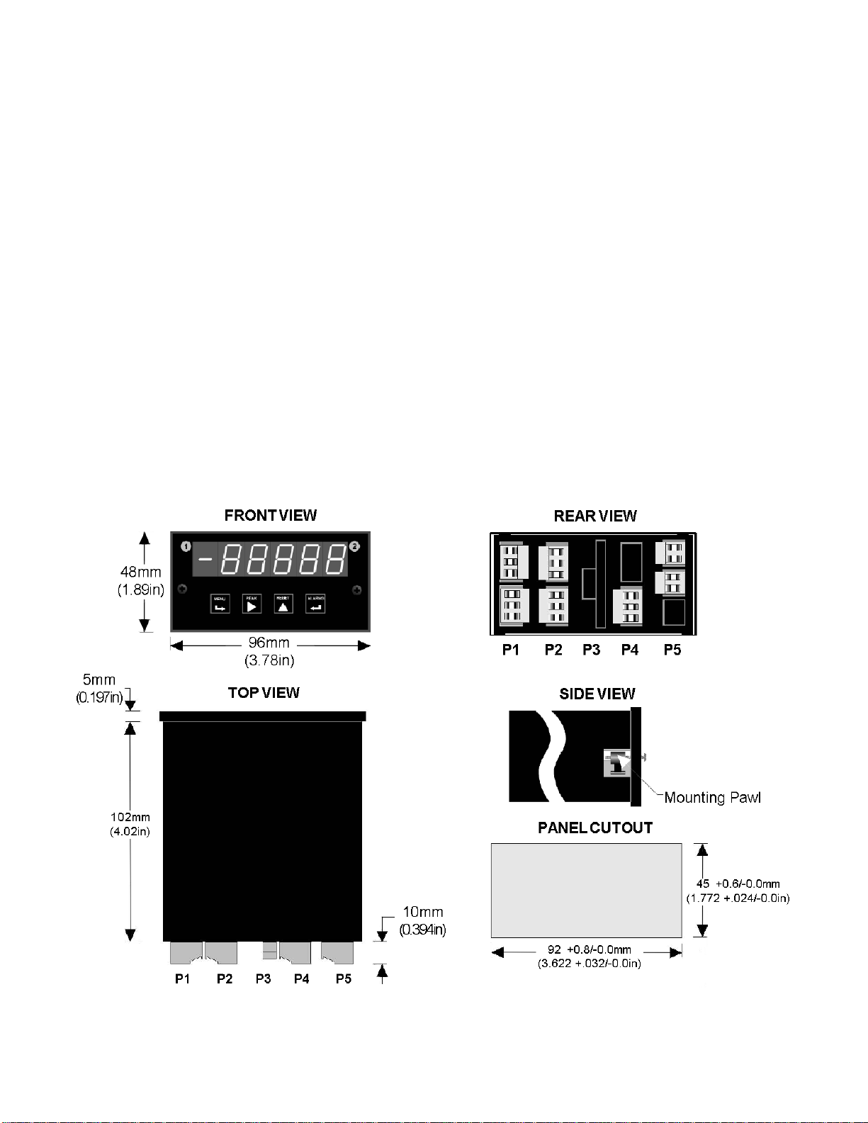
The meter case conforms to the 1/8 DIN size standard. It is made of high impact, 94V-0 ULrated plastic and is watertight to NEMA-4 (IP65) when panel mounted (not verified for UL
certification). Mounting is from the front of the panel and requires less than 110 mm behind the
panel. Power and signal wiring is via removable plugs conforming to UL61010C safety
standards. All output options are isolated from meter and power ground to 250 Vac.
Extended IPM meter versions can linearize nonlinear inputs. Up to 180 data points may be
linearized by a computer program that stores setup parameters in nonvolatile memory.
Extended meters can also display rate of change, for example to display flow rate based on
changing tank level.
Alarm or setpoint control is provided by an optional relay board with two or four Form C 8A
mechanical relays or two or four Form A 130 mA solid state relays. The setpoints may be
latching or non-latching, be energized above or below the setpoint, or operate in a fail-safe
mode. The relays can operate from the filtered signal to reduce relay chatter or from the
unfiltered signal for fastest response. Snubber circuits and a programmable relay switching
time delay extend relay contact life.
An isolated analog output of 4-20 mA, 0-20 mA, 0-10V or -10 to +10V can be provided by an
optional analog output board. The output is linearized to the display and can operate from the
filtered or unfiltered signal input. It can be scaled via front panel pushbuttons or the meter’s
serial interface.
USB, RS232, or RS485 (2-wire half-duplex or 4-wire full-duplex) serial communications options
are available with Series 2 meters utilizing the Modbus protocol or a simpler custom ASCII
protocol. Modbus operation includes RTU or ASCII modes, up to 247 digital addresses, and up
to 32 devices per RS485 line without a repeater. A USB-to-RS485 converter board allows a
meter to be interfaced to a PC and to multiple meters on an RS485 network.
3
Page 4
4. RECEIVING & UNPACKING
Your meter was carefully tested and inspected prior to shipment. Should the meter be
damaged in shipment, notify the freight carrier immediately. In the event the meter is not
configured as ordered or the unit is inoperable, return it to the place of purchase for repair or
replacement. Please include a detailed description of the problem.
5. SAFETY CONSIDERATIONS
Warning: Use of this equipment in a manner other than specified may impair the pro-
tection of the device and subject the user to a hazard. Visually inspect the unit for signs of
damage. If the unit is damaged, do not attempt to operate.
Caution:
• This unit must be powered with AC (mains) from 95-240 Vac ±10% with the high voltage
power supply option, or 12-30 Vac (10-48 Vdc) with the low voltage power supply option.
Verify that the proper power option is installed for the power to be used. This meter has no
AC (mains) switch. It will be in operation as soon as power is connected.
• The 95-240 Vac mains connector (P1 Pins 1-3) is colored Green
other input and output connectors. The 12-30 Vac (10-48 Vdc) mains connector is colored
Black
.
• Do not make signal wiring changes or connections when power is applied to the instrument.
Make signal connections before power is applied. If reconnection is required, disconnect
the AC (mains) power before such wiring is attempted.
• To prevent electrical or fire hazard, do not expose the instrument to excessive moisture.
• Do not operate the instrument in the presence of flammable gases or fumes; such an
environment constitutes a definite safety hazard. This meter is designed to be mounted in a
metal panel.
• Verify the panel cutout dimensions, and mount according to instructions.
Symbols used
Caution (refer to accompanying documents)
Operating environment:
Caution, risk of electric shock. Both direct and alternating current.
Equipment protected throughout by double
insulation or reinforced insulation.
Earth (ground) terminal.
to differentiate it from
The meter is Class II (double insulated) equipment designed for use in Pollution degree 2.
4
Page 5
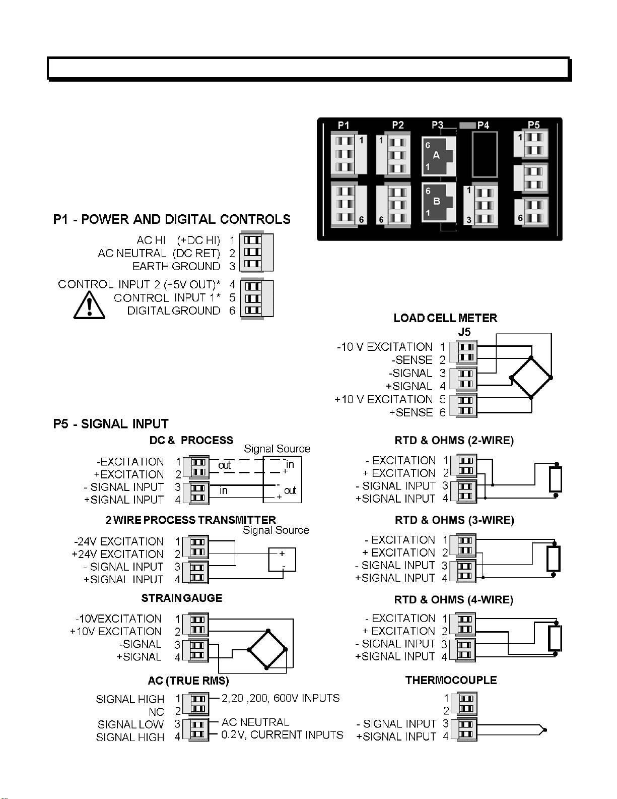
6. CONNECTOR WIRING INFORMATION
CONNECTORS
Connectors for signal and power are UL-rated
screw-clamp terminal blocks that plug into
mating jacks on the printed circuit board.
Communication connectors are a single RJ11
plug for RS232, dual RJ11 plugs for RS485,
dual RJ45 plugs for RS485 Modbus, or USB.
Note: Control inputs 1 & 2 of P1 are menu
selectable.
Warning: Hazardous voltages may be present
on pins 4, 5 & 6 of P1 since digital ground is tied
to pin 3 of P5 (-Signal Input). Keep pin 3 close to
earth ground to minimize common mode voltage
or shock hazard at pins 4, 5 & 6 of P1.
5
Page 6
P3 - SERIAL COMMUNICATIONS P4 - ANALOG OUTPUT
RS232 INTERFACE Computer
N/C
ISO GND
RX
TX
RTS
N/C
RS485 INTERFACE - FULL DUPLEX
ISO GND
BRX
ARX
ATX
BTX
ISO GND
6
5
4
3
2
1
GND
TX
RX
RTS
RS485 INTERFACE - HALF DUPLEX
6
5
4
3
2
1
GND
BTX
ATX
ARX
ARX
GND
ISO GND
ATX / ARX
BTX / BRX
ISO GND
6
5
4
3
2
1
GND
ATX / ARX
BTX / BRX
GND
RS485-MODBUS - FULL DUPLEX RS485-MODBUS - HALF DUPLEX
(A') RXD0 (B') RXD1 +
(B) TXD1 *
(A) TXD0 -
ISO GND
1
2
3
4
5
6
7
8
TXD0
TXD1
RXD1
RXD0
GND
(B) TX/RXD1
(A) TX/RXD0
ISO GND
6
1
2
3
4
5
6
7
8
(B) TX/RXD1
(A) TX/RXD0
GND
Page 7
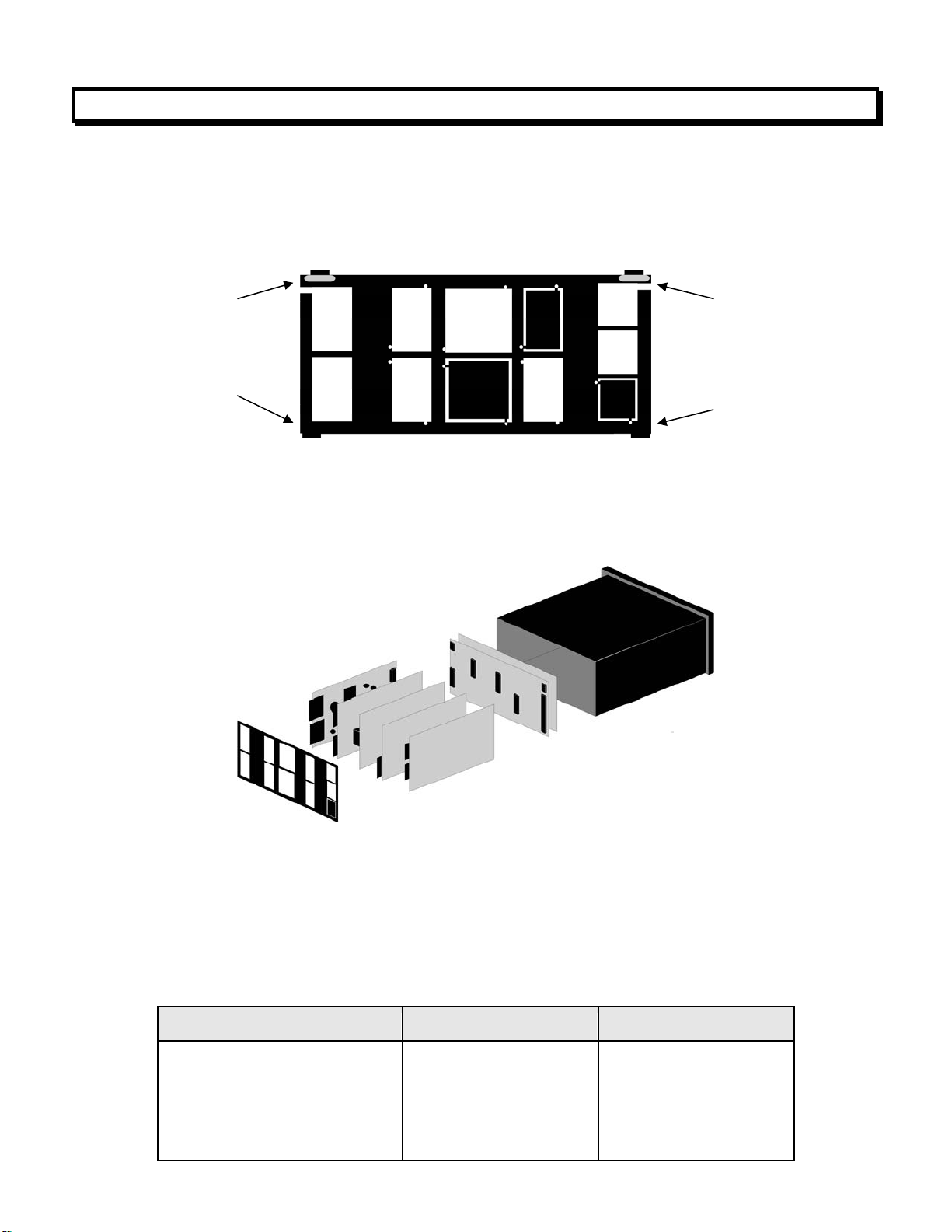
7. MECHANICAL ASSEMBLY
REMOVING THE REAR PANEL
First remove any connectors. Use one hand to press in the two sides of the rear of the
case, and the other hand to press down the two protruding tab releases at the top of the
rear panel (see figure below). This will unhook the rear panel from the case.
Retaining tab
with tab release
Retaining tab
Retaining tab
with tab release
Retaining tab
Rear Panel
REMOVING THE ELECTRONICS
With the rear panel removed, grasp the power supply board to the left and signal conditioner board to the right, and carefully slide the electronic assembly out through the rear of
the case. (see figure below).
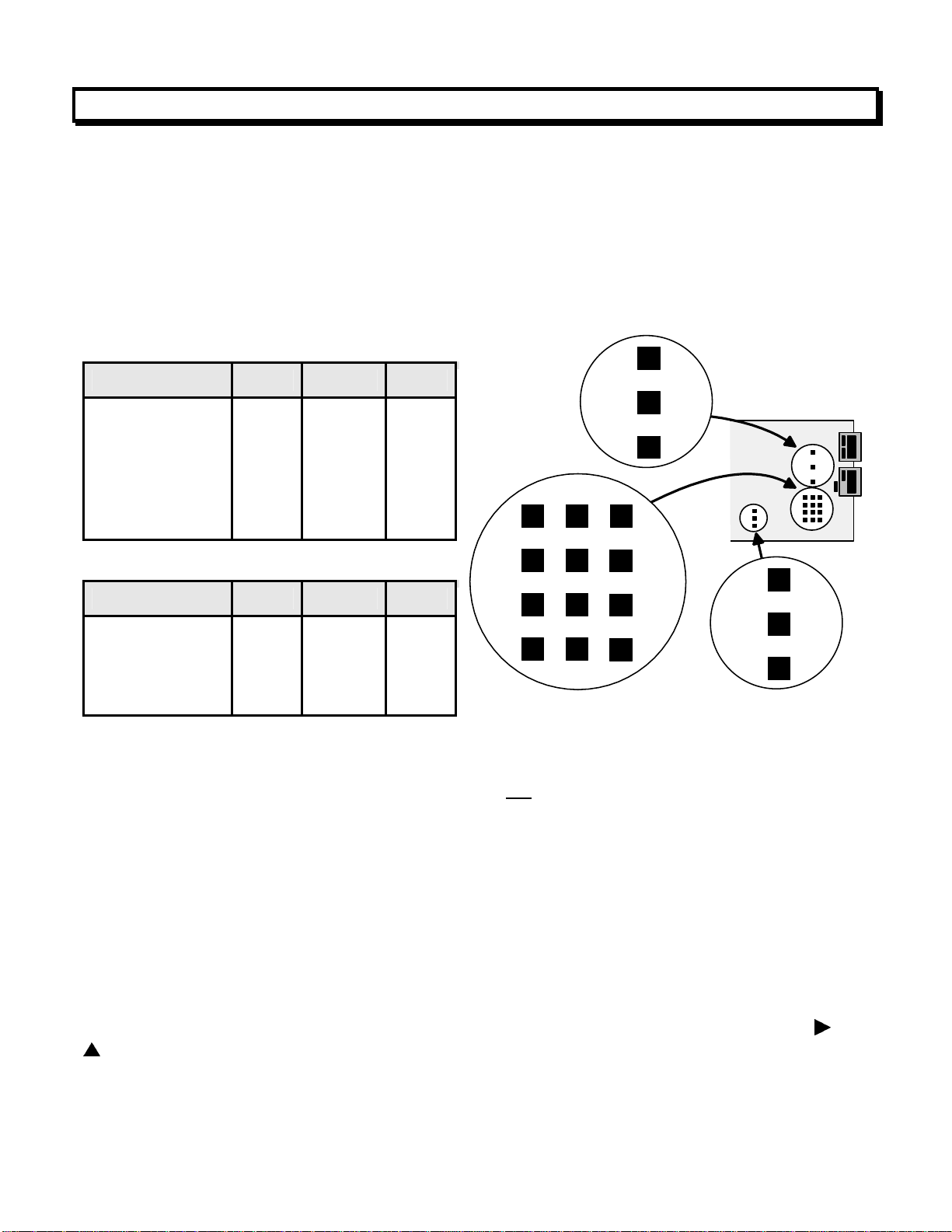
INSTALLING NEW 0PTION BOARDS
Options boards plug into the main board at the front of the meter. These are plug-and-play
and may be
in the field. They will be recognized by the software, which will provide access to the menu
items associated with that board. If necessary, remove rear panel knockouts for new
boards. Boards plug into connectors as follows:
Option Board Main Board Plug Rear Panel Jack
Power supply
Relay board
Serial interface board
Analog output board
Signal conditioner board
P11
P12
P13
P14
P15
J1
J2
J3
J4
J5
7
Page 8
Note: Corresponding main board and option board connectors have the same number of
electrical lines. When an option board is correctly installed, the top and bottom edges of the
main board and option board are aligned.
REASSEMBLING YOUR METER
Slide the electronics assembly into the case until the display board is seated flush against
the front overlay. Insert the bottom tabs of the rear panel into the case, and then carefully
align the board connectors with the openings in the rear panel. If necessary, remove any
rear panel knockouts for new option boards that may have been installed. Ensure that all
option boards are properly aligned with the molded board retaining pins on the inside of the
rear panel. Once the rear panel is in place, reinstall the input/output screw clamp terminal
plugs.
PANEL MOUNTING
Ensure that the panel mounted gasket is in place against the back of the bezel. Turn the two
mounting screws counterclockwise until the space between the mounting pawl and the rear
of the gasket is greater than the panel thickness. Insert the meter in the panel cutout. Turn
the mounting screws clockwise until the meter is securely mounted in the panel. Do not
overtighten.
Dimensioned case drawings
8
Page 9
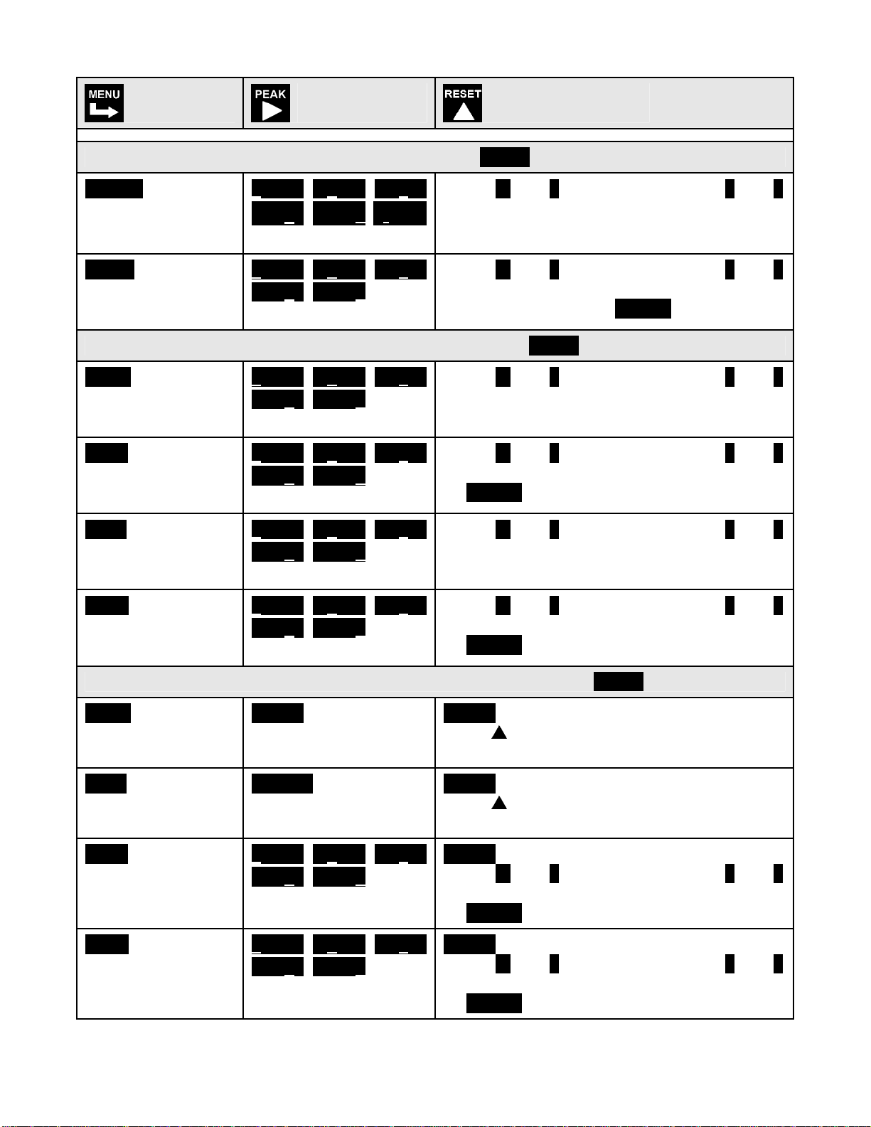
8. FRONT PANEL SETUP KEYS
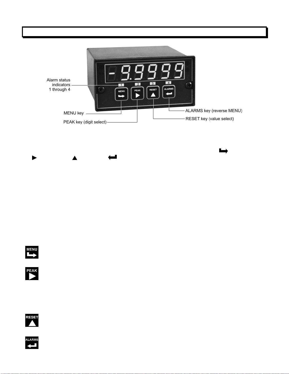
Meter Front Panel
There are four front panel keys, which change function for the Run Mode and Menu Mode,
effectively becoming eight keys. The keys are labeled with alphanumeric captions (MENU,
PEAK, RESET, ALARMS) for the Run Mode and with symbols (
right triangle, up triangle, left arrow) for the Menu Mode.
FRONT PANEL LOCKOUT
right arrow,
The Menu Mode will not work with most meters as received from the factory, since all menu
items have been disabled in software and a lockout jumper is in place. That jumper needs to
be removed for the Menu Mode to work, and menu items under Loc 1, Loc 2 and Loc 3 then
need to be set to "0" via the front panel for these menu items to be unlocked See Section 9.
The paragraphs below assume that all menu items have been unlocked.
MENU MODE KEY ACTION
In the Menu Mode, pressing a key momentarily advances to the next menu item. Holding
down a key automatically advances through multiple menu items for fast menu navigation.
KEYS IN RUN MODE
MENU Key. Pressing MENU from the Run Mode enters the Menu Mode. Pressing
MENU repeatedly will step the meter through the various menu items (if these have not
been locked out) and then back to the Run Mode.
PEAK Key. Pressing PEAK normally causes the peak value of the input signal to be
displayed. The peak display then blinks to differentiate it from the normal present value
display. Pressing PEAK again returns the display to the present value. The PEAK key
can also be programmed to display Valley, alternating Peak or Valley, or to Tare the
reading to zero. When Peak or Valley is selected, periodic horizontals bars at the top of
the display indicate Peak, and periodic horizontals bars at the bottom indicate Valley.
RESET Key. Pressing RESET with PEAK resets peak and valley values. Pressing
RESET with ALARMS resets latched alarms. Pressing RESET with MENU performs a
meter reset (same as power on). Meter reset can also be applied via a rear panel
connect or a serial ASCII command.
ALARMS Key. Pressing ALARMS once displays the setpoint for Alarm 1. Pressing it
again displays the setpoint for Alarm 2. Pressing it again returns to the present value.
9
Page 10

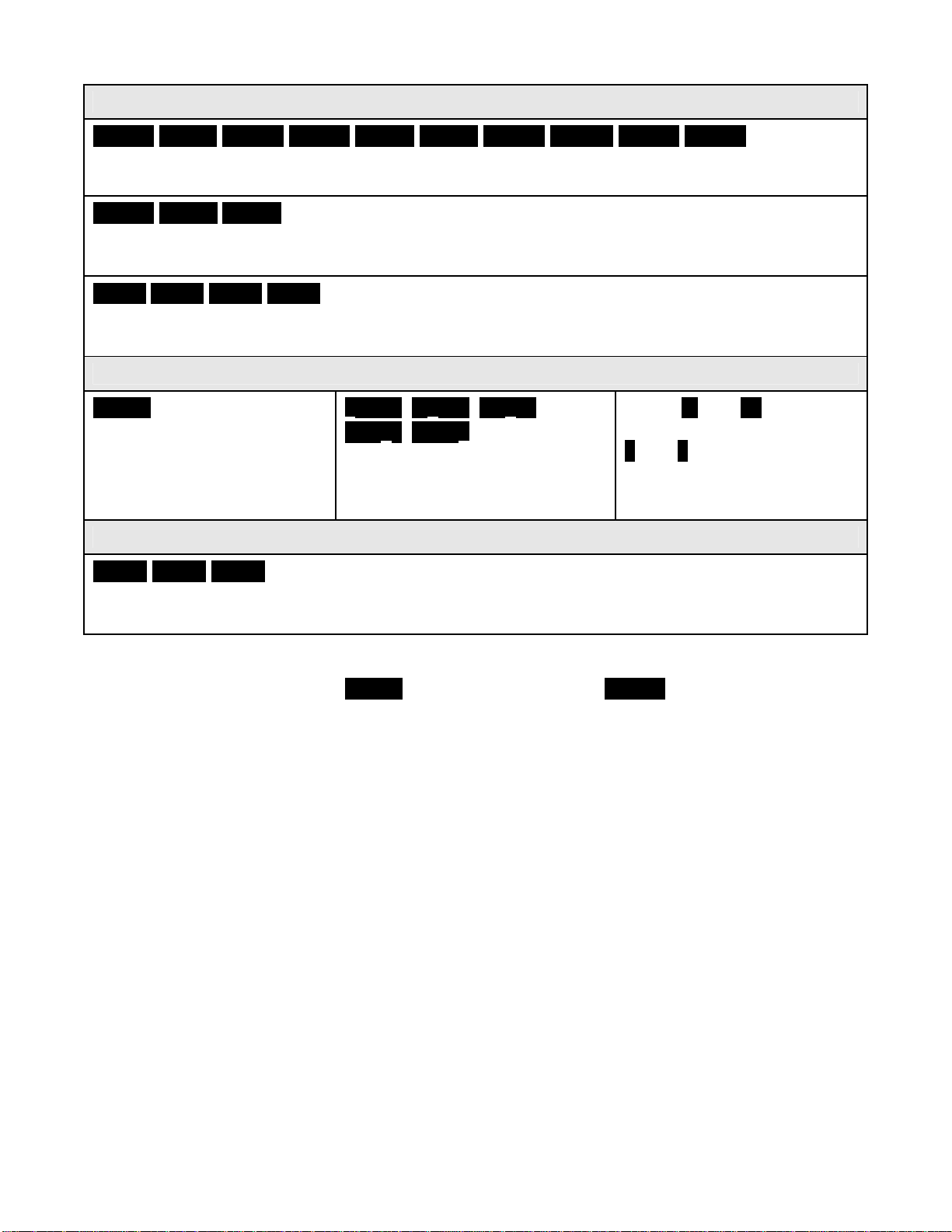
KEYS IN MENU MODE
Right Arrow Key (MENU). Pressing
have been enabled and then back to the Run Mode. With the DC signal conditioner
board and no option boards, available menu items are _InPut, SEtuP, ConFG, _FiLtr,
dEc.Pt, SCALE, OFFst, Loc 1, Loc 2, Loc 3. If a change has been made to a menu
item, that change is saved to non-volatile memory when the
and StoreE is displayed briefly.
Right Triangle Key (Digit Select).
steps the meter through all menu items that
key is pressed next,
• Pressing
meter's signal conditioner. For the DC signal conditioner, these are _dC U, _dC A
and _rAtio.
• Pressing
menus items sequentially selects digit positions 1 - 5, as indicated by a flashing digit:
00000, 00000, 00000, 00000, 00000.
• Pressing
which will flash: d.dddd dd.ddd ddd.dd dddd.d ddddd. .ddddd.
Up Triangle Key (Value Select). Pressing
decimal point position) will increment that item. Pressing MENU will save any changes.
Left Arrow Key (Reverse Menu). Pressing
except that menu items are brought up in reverse order.
from the InPut menu brings up all meter functions available with the
from the SEtuP, ConfFG, FiLtr, SCALE, OFFSt, Loc 1, Loc 2 or Loc 3
from the dEC.Pt menu item sequentially selects decimal point positions,
for a flashing item (digit position or
has the same effect as the MENU key,
10
Page 11
9. ENABLING & LOCKING OUT MENU ITEMS
For security reasons and ease of meter operation, any and all menu
items may be disabled or "locked out" so that they are no longer directly
accessible from the front panel. Each function to be disabled
in menu items Loc 1, Loc 2 or Loc 3, and each function to be enabled
set to "0." The top menu items Loc 1, Loc 2 and Loc 3 can in turn be
locked out by installing an internal hardware jumper. With the jumper
installed
the jumper removed
Loc 2 and Loc 3.
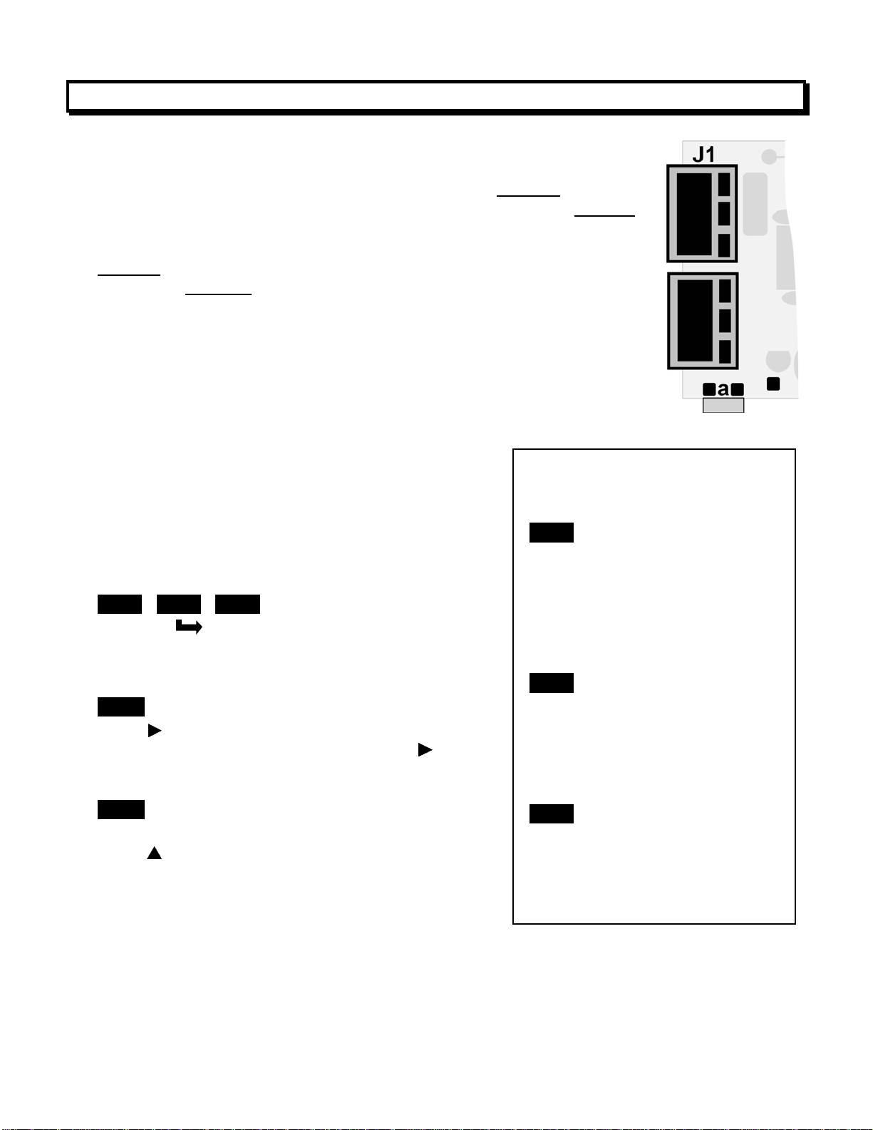
SETTING HARDWARE LOCKOUT JUMPER
To access the lockout jumper, remove the rear panel per Section 9 and
locate jumper “a” in the lower portion of the power supply board next to
the input connectors (see figure at right).
SETTING SOFTWARE LOCKOUTS
When setting up the meter, it may be necessary to
enable specific menu items by setting the corresponding lockout digit to 0. Be sure to reset the
lockout digit to "1" if you do not want the menu item
to be changed by an operator.
Loc 1 Loc 2 Loc 3
Press the MENU key until Loc 1, Loc 2 or Loc 3
is displayed, as desired. Note: the hardware lockout
jumper must be removed (see above).
11111
Press
1’s and 0’s. The left digit will flash. Press
step to the next digit, which will flash.
00000
12345
Press
menu item or to "1" to disable. Press MENU to enter.
See the table to the right for list of menu items that
can be enabled or disabled.
, the operator only has access only to enabled menu items. With
, the operator also has access to menu items Loc 1,
to display the lockout status, consisting of
again to
to set the flashing digit to "0" to enable the
is set to "1"
Enabled or Disabled
Menu Items
Loc 1
1 - Input type selection.
2 - Meter setup, configuration
& decimal pt.
3 - Filter selection.
4 - Scale or Lo, Hi input.
5 - Offset or Lo, Hi reading
Loc 2
2 - Alarm setup.
3 - Alarm setpoint value
programming.
4 - Analog output scaling.
5 - Serial interface setup.
Loc 3
2 - View peak value
3 - View alarm setpoints
4 - Reset (peak & latched alarms)
5 - Reset (meter reset)
is
11
Page 12
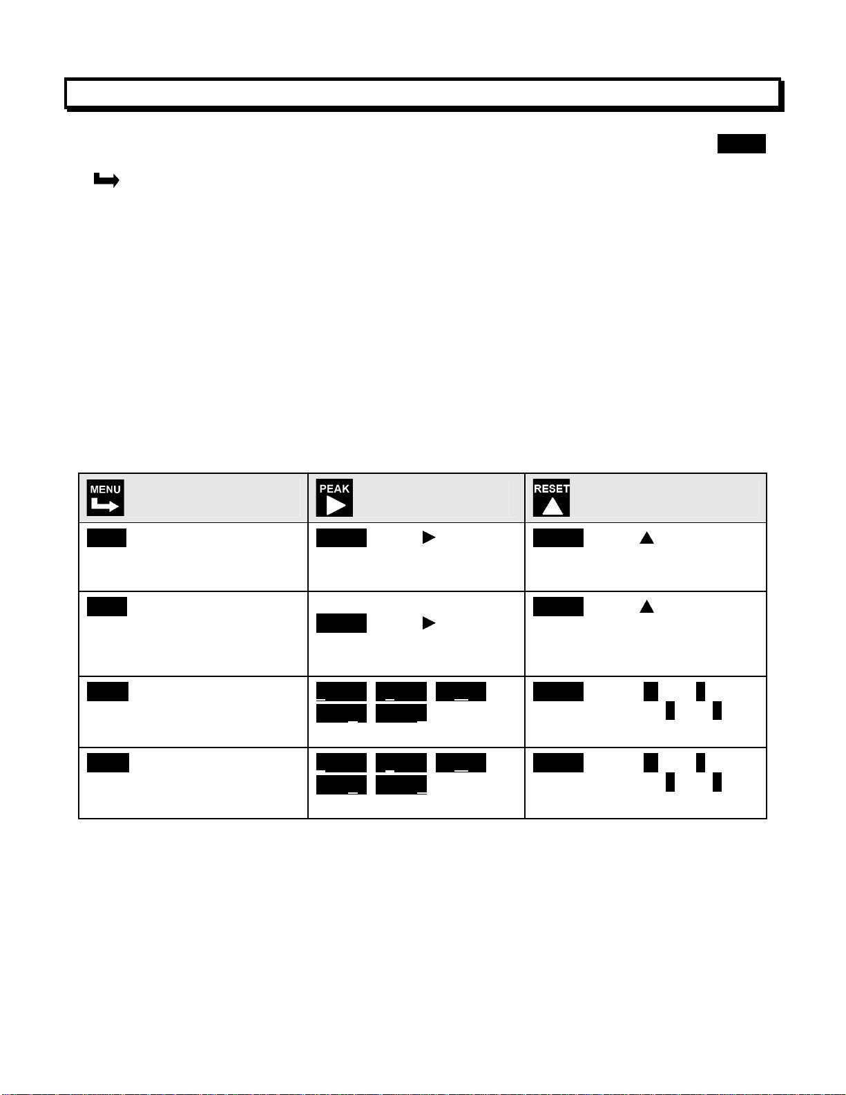
10. READING COORDINATES OF 2 POINTS SCALING METHOD
When the reading coordinates of 2 points scaling method has been selected under SEtuP,
the four menu items below will appear ahead of all other menu items when the MENU or
key is first pressed from the run mode.
This scaling method applies a straight line fit between two points, which are determined
from actual transducer signals and the desired corresponding meter readings. A low signal,
such as the output of a pressure transducer at zero pressure, and high signal, such as the
output of the same transducer at a known high pressure, are applied to the meter. The
desired corresponding low and high readings are then entered from the front panel. The
meter then applies straight line fit between the high and low calibration points. This scaling
method has the advantage of calibrating the transducer and meter as a system. The actual
voltage or current at either point does not need to be known. This method is ideal for
process and load cell meters, which require zero and span adjustment. It is also available
for DC or AC meters. It is not available with thermocouple or RTD meters.
The programming example below is for a process meter used with a 4-20 mA pressure
transducer for 0 to 100 psi. Decimal points are set separately using the dEC.Pt menu.
Press Menu Select
Key
Lo In Apply low signal input
(e.g., transducer output for 0
psi).
Hi In Apply high signal input
(e.g., transducer output for
known 100.00 psi source).
Lo rd
Mode to enter desired low
reading (e.g., 0.00).
Hi rd
Mode to enter desired high
reading (e.g., 100.00).
Press Digit Select
Key
_40.21 Press to display
reading at low signal input
(e.g., 4.021 mA).
200.94 Press to display
reading at high signal input
(e.g., 20.094 mA).
000.00 000.00 000.00
000.00 000.00 Select digit
to flash.
000.00 000.00 000.00
000.00 000.00 Select digit
to flash.
Press Value Select
Key
_40.21 Press to store low
reading.
200.94 Press to store high
reading.
100.00 Select -9 thru 9 for
flashing first digit, 0 thru 9 for
other flashing digits.
100.00 Select -9 thru 9 for
flashing first digit, 0 thru 9 for
other flashing digits.
12
Page 13
11. DC VOLTS, AMPS, PROCESS, STRAIN INPUT
The DC Volts, Amps, Process and Strain meters utilize the DC signal conditioner board, which
needs to be configured via jumpers for the desired voltage or current range. All signal ranges
are factory calibrated with calibration factors stored in EEPROM. The meter software
recognizes the board and will bring up the appropriate menu items for it; however, it does not
recognize the jumper settings. Please see further manual sections for setup of the following:
relay output (16), analog output (17), communications (18), and transducer excitation output
(19).
Voltage Ranges
FS Input E1 E2 E3
±200.00 mV
±2.0000 V
±20.000 V
±200.00 V
±300V (UL)
±600V (not UL)
A
A
B
B
B
B
f
f
h
h
g
g
b
a
b
a
a
a
B
A
a
E3
h
f
Current Ranges
b
g
FS Input E1 E2 E3
±2.0000 mA
±20.000 mA
±200.00 mA
±5.000 A
1. Use 5 mm (0.2") jumpers for locations designated by a capital letter.
2. Use 2.5 mm (0.1") jumpers for locations designated by a lower case letter.
3. Store spare jumpers on an unused jumper post not
SCALE & OFFSET SETUP
A
A
A
A
e, g
d, g
c, g
a, b, g
b
b
b
b
associated a capital letter.
c
d
e
E1
E2
b
a
For DC voltmeters & ammeters, a scale factor of 1 and an offset of 0 are used for direct
readings in (milli)volts or (milli)amperes. Decimal point selection does not affect the displayed
digits. For example, 0-20V or 0-20 mA signals can both be displayed as 0-20000. A full scale
of 20000 may be displayed as 20.000 mA or 20000 µA. Use with a current shunt will require a
scale factor to be set. For example, for a 500-100 (500A, 100 mV) shunt, divide 5000 (the
desired full scale display with 0.1A resolution) by 10000 (displayed value with 100 mV when
the scale factor is 1.0) for a scale factor of 0.5.
For process & strain meters, scaling is normally set up from the front panel using the
keys. The meter allows three scaling methods to be selected: 1) Scale and offset,
2) Coordinates of 2 points, and 3) Reading coordinates of 2 points. Only menu items
applicable to the selected method will be presented.
13
and
Page 14
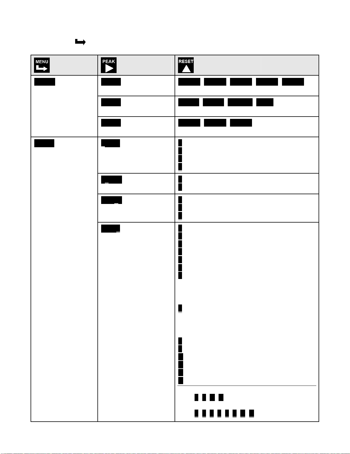
KEYSTROKES FOR SETUP
If the MENU
key does not work, see Section 9 “Enabling & Locking Out Menu Items.”
Press Menu
Select Key
_InPut
Selection of signal
input type & range
SEtuP
Meter Setup
Press Digit
Select Key
_dC U
DC Volts
_dC A
DC Amps
_rAtio
Strain gauge & ratio
00_00
Display selection with
scale factor of 1.
00 _00
Power line frequency
00_ 00
Scaling method
Press Value Select
Key
__0.2U __2.0U _20.0U 200.0U 600.0U
0.2, 2, 20, 200, 660V FS
__2.0a _20.0a _200.0a _5.0a
0.2, 20, 200 mA, 5A FS
__0.2U __2.0U _20.0U
0.2, 2, 20V FS.
0 4-1/2 digits (±20,000)
1 Remote display (±99,999)
2 4-1/2 digits, counts by 10 (±20,000)
3 3-1/2 digits (±2,000)
0 Noise minimized for 60 Hz
1 Noise minimized for 50 Hz
0 Scale and offset method
1 Coordinates of 2 points method
2 Reading coordinates of 2 points method
00_00
Control inputs 1 & 2:
True = logic 1 (0V or
tied to digital ground)
False = logic 0 (5V or
open)
0 1 = Reset, 2 = Meter Hold
1 1 = Function Reset, 2 = Peak or Valley
2 1 = Hold, 2 = Peak or Valley Display
3 1 = Hold, 2 = Tare
4 1 = Peak or Valley Display, 2 = Tare
5 1 = Tare, 2 = Reset
6 1 = 1, 2 = 1, decimal point = XXXXX
1 = 0, 2 = 1, decimal point = XXXX
.X
1 = 1, 2 = 0, decimal point = XXX.XX
1 = 0, 2 = 0, decimal point = XX
.XXX
7 1 = 1, 2 = 1, decimal point = XXXX.X
1 = 0, 2 = 1, decimal point = XXX
1 = 1, 2 = 0, decimal point = XX
1 = 0, 2 = 0, decimal point = X
.XX
.XXX
.XXX.X
8 1 = Function Reset, 2 = Display Blank
9 1 = Hold, 2 = Display Blank
A 1 = Peak or Valley, 2 = Display Blank
B 1 = Tare, 2 = Display Blank
C 1 = Valley Display, 2 = Peak Display
D 1 = Tare, 2 = Reset Tare to Zero
Both inputs 1 and 2 set to logic 1 for selec-
tions 2, 4, A, C = Function Reset
Both inputs 1 and 2 set to logic 1 for selec-
tions 0, 1, 3, 5, 8, 9, B, D = Meter Reset
14
Page 15
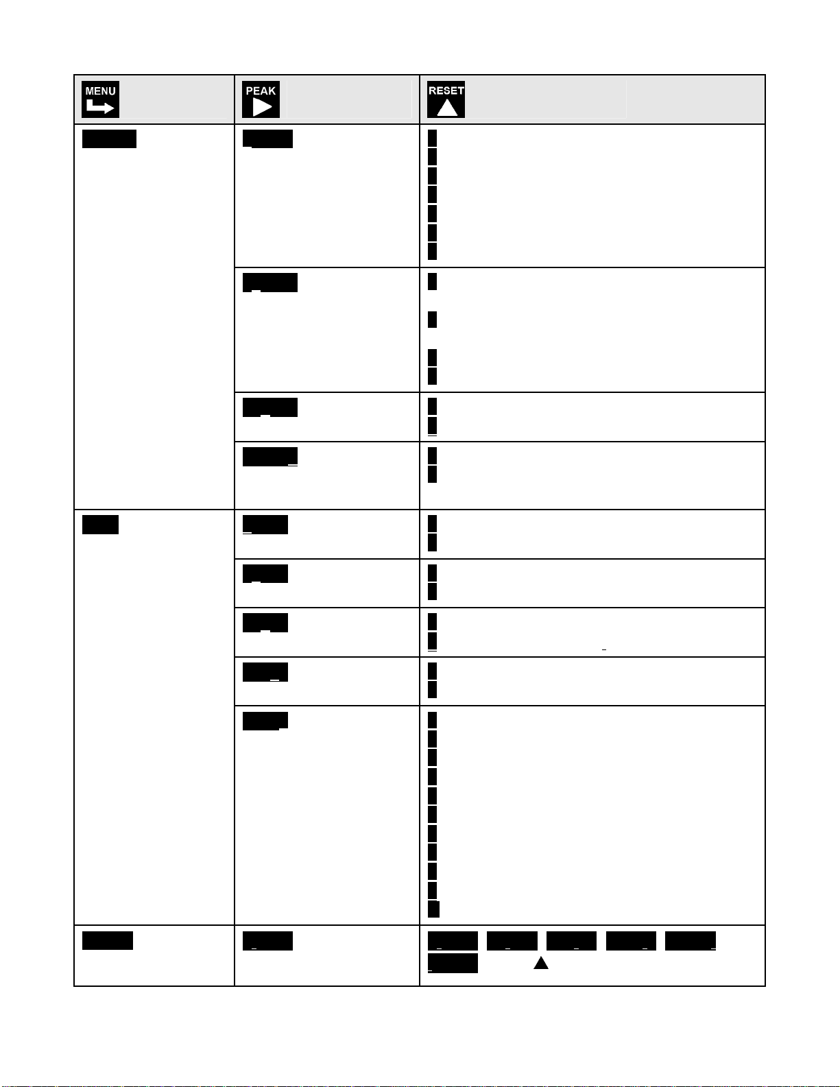
Press Menu
Select Key
Press Digit
Select Key
Press Value Select
Key
ConFG
Meter Configuration
FiLtr
Filtering
000 _0
Operation as a rate of
change meter.
Extended meter only.
_0 _ _0
Operation of front
panel PEAK button
and rear connector for
Peak or Valley Display
000 _ 0
Auto-tare
000 _ 0
Nonlinear input scaling
Extended meter only.
00000
Alarm filtering
0 Not rate of change
1 Rate x 0.1
2 Rate x 1
3 Rate x 10
4 Rate x 100
5 Rate x 1000
6 Rate x 10000
0 Peak Display. Also selects “Peak” in
“Peak or Valley” at connector above.
1 Valley Display. Also selects “Valley” in
“Peak or Valley” at connector above.
2 Peak (1st push), Valley (2nd push)
3 Front panel Tare
0 Meter comes up in normal run mode.
1 Meter comes up in auto-tare mode
0 Linear input
1 Custom curve linearization
0 Unfiltered output
1 Filtered output
dEc.Pt
Dec. point selection
00000
Peak & Valley filtering
00000
Display filtering
00000 Adaptive filter
threshold
00000
Input signal filtering.
Can be applied to display, setpoint, analog
output, data output.
d.dddd
Decimal point flashes.
0 Unfiltered Peak & Valley
1 Filtered Peak & Valley
0 Display batch average every 16 readings
1 Display filtered signal
0 Low adaptive filter threshold level
1 High adaptive filter threshold level
0 Autofilter
1 Batch average, 16 readings
2 Moving average, 0.08 sec.
3 Moving average, 0.15 sec.
4 Moving average, 0.3 sec.
5 Moving average, 0.6 sec.
6 Moving average, 1.2 sec.
7 Moving average, 2.4 sec.
8 Moving average, 4.8 sec.
9 Moving average, 9.6 sec.
A Unfiltered
d.dddd dd.ddd ddd.dd dddd.d ddddd.
.ddddd Press to shift the decimal point.
15
Page 16
Press Menu
Select Key
Press Digit
Select Key
Press Value Select
Key
Scaling method “Scale and Offset” if selected under SEtuP
SCALE
Scale factor
OFFst
Offset value
0.0000 0.0000 0.0000
0.0000 0.0000 0.0000
Select digit to flash.
0.0000 0.0000 0.0000
0.0000 0.0000
Select digit to flash.
Select -9 thru 9 for flashing first digit, 0 thru 9
for other flashing digits. Select decimal point
location when decimal point is flashing.
Select -9 thru 9 for flashing first digit, 0 thru 9
for other flashing digits. Decimal point
location is selected by dEC.Pt.
Scaling method “Coordinates of 2 points” if selected under SEtuP
Lo In.
Low signal input.
Lo rd
Desired reading at
Lo In.
Hi In.
High signal input.
0.0000 0.0000 0.0000
0.0000 0.0000
Select digit to flash.
0.0000 0.0000 0.0000
0.0000 0.0000
Select digit to flash.
0.0000 0.0000 0.0000
0.0000 0.0000
Select digit to flash.
Select -9 thru 9 for flashing first digit, 0 thru 9
for other flashing digits. Decimal point is set
by input range chosen.
Select -9 thru 9 for flashing first digit, 0 thru 9
for other flashing digits. Decimal point is set
by dEC.Pt.
Select -9 thru 9 for flashing first digit, 0 thru 9
for other flashing digits. Decimal point is set
by input range chosen.
Hi rd.
Desired reading at
Hi In.
0.0000 0.0000 0.0000
0.0000 0.0000
Select digit to flash.
Select -9 thru 9 for flashing first digit, 0 thru 9
for other flashing digits. Decimal point is set
by dEC.Pt.
Scaling method “Reading coordinates of 2 points” if selected under SEtuP
Lo In.
Low signal input.
Hi In.
High signal input.
Lo rd
Desired reading at
Lo In.
_0.021
Apply a low reference
signal to the meter.
_20.094
Apply a high reference
signal to the meter.
0.0000 0.0000 0.0000
0.0000 0.0000
Select digit to flash.
_0.021
Press
to store the low signal input in the
meter.
_0.021
Press to store the high signal input in the
meter.
0.0000
Select -9 thru 9 for flashing first digit, 0 thru 9
for other flashing digits. Decimal point is set
by dEC.Pt.
Hi rd.
Desired reading at
Hi In.
0.0000 0.0000 0.0000
0.0000 0.0000
Select digit to flash.
6.7500
Select -9 thru 9 for flashing first digit, 0 thru 9
for other flashing digits. Decimal point is set
by dEC.Pt.
16
Page 17
Option board dependent menu items
ALSEt. ALS34 dEU1H dEU2H dEU1b dEU2b dEU3H DEU4H DEU3b DEU4b
Menu items related to alarm setup These will only appear if a relay board is detected. If so,
please see Section16.
AnSEt. An Lo. An Hi..
Menu items related to analog output setup. These will only appear if an analog output
board is detected. If so, see Section 17.
SEr 1. SEr 2. SEr 3. SEr 4.
Menu items related to serial communications. These will only appear if an RS232, RS485
or USB I/O board is detected. If so, see Section 18.
Gain correction
-Gain .
Gain correction for negative
signals. Keep at 00.000% to
make positive and negative
gains equal.
Menu lockout items
Loc 1. Loc 2. Loc 3.
Menu items used to enable or lock out (hide) other menu items. Loc menu items may in turn
be locked out by a hardware jumper. Please see Section 9.
* Scaling method 2, “Reading Coordinates of 2 Points Scaling Method,” will appear before all
other Menu items, including _InPut. Decimal point is set by dEC.Pt.
0.0000 0.0000 0.0000
0.0000 0.0000
Gain correction from -29.999%
to +29.9999% of positive gain
for negative inputs.
Select -2 thru +2 for flashing
most significant digit. Select
0 thru 9 for other flashing
digits.
17
Page 18

12. LOAD CELL & MICROVOLT INPUT
The Load Cell and Microvolt meters utilize the load cell signal conditioner board, which offers
sensitivity to ±20 mV full scale and 4 or 6-wire load cell connection. This board needs to be
configured via jumpers for the desired voltage range. All signal ranges are factory calibrated
with calibration factors stored in EEPROM. The meter software recognizes the board and will
bring up the appropriate menu items for it; however, it does not recognize the jumper settings.
Please see further manual sections for setup of the following features: relay output (16),
analog output (17), communications (18), and transducer excitation output (19).
RANGE SELECTION VIA JUMPERS
Ranges & Display with
Scale Factor = 1
Input Jumpers
±20 mV
±50 mV
±100 mV
±250 mV
±500 mV
Notes 1. See Section 19 to select 10V excitation.
2. Jumpers are 2.5 mm (0.1 in).
SCALE & OFFSET SETUP
For DC microvolt meters, a scale factor of 1 and an offset of 0 are used for direct readings in
microvolts or millivolts. Decimal point selection does not affect the displayed digits. For
example, 20 mV can be displayed as 20.000 mV or 20000 µV. The decimal point is set
separately.
For load cell applications, scaling is set up from the front panel using the
meter allows three scaling methods to be selected: 1). Manual scale and offset, 2) Coordinates
of 2 points, and 3) Reading coordinates of 2 points. Please see the Glossary for an explanation
of each method.
e
a
b
c
d
Full scale
display
±20000
±50000
±10000
±25000
±50000
and keys. The
18
Page 19

KEYSTROKES FOR SETUP
If the MENU
key does not work, see Section 9 “Enabling & Locking Out Menu Items.”
Press Menu
Select Key
_InPut
Selection of signal
input type & range
SEtuP
Meter Setup
Press Digit
Select Key
_Strn
Strain or ratiometric
_dC U U
DC millivolts
00_00
Display type
00 _00
Power line frequency
00_ 00
Scaling method
00_00
Rear connector control
inputs 1 & 2.
True = logic 1 (0V or
tied to digital ground)
False = logic 0 (5V or
open)
Press Value Select
Key
_20.0____50.0_ _100.0 _250.0 _500.0
20, 50, 100, 250, 500 mV FS voltage
_20.0____50.0_ _100.0 _250.0 _500.0
20, 50, 100, 250, 500 mV FS voltage
0 4-1/2 digit meter, counts by 1
1 5-digit remote display (±99,999)
2 4-1/2 digit meter, counts by 10
3 3-1/2 digit meter
0 Noise minimized for 60 Hz
1 Noise minimized for 50 Hz
0 Scale and offset method
1 Coordinates of 2 points method
2 Reading coordinates of 2 points method
0 1 = Reset, 2 = Meter Hold
1 1 = Function Reset 2 = Pk or Valley Disp.
2 1 = Meter Hold 2 = Pk or Valley Disp.
3 1 = Meter Hold 2 = Tare
4 1 = Peak or Valley 2 = Tare
5 1 = Tare 2 = Reset
6 1 = 0, 2 = 0, decimal point 1= XXXXX
1 = 1, 2 = 0, decimal point 1 = XXXX.X
1 = 0, 2 = 1, decimal point 1 = XXX
.XX
1 = 1, 2 = 1, decimal point 1 = XX.XXX
7 1 = 0, 2 = 0, decimal point 2 = XXXX.X
1 = 1, 2 = 0, decimal point 2 = XXX
1 = 0, 2 = 1, decimal point 2 = XX
.XX
.XXX
1 = 1, 2 = 1, decimal point 2 = X.XXX.X
8 1 = Function Reset 2 = Display Blank
9 1 = Hold 2 = Display Blank
A 1 = Peak or Valley 2 = Display Blank
B 1 = Tare 2 = Display Blank
C 1 = Valley Display 2 = Peak Display
D 1 = Tare 2 = Tare Reset
Both control inputs 1 & 1 set to 1 for selec-
tions 2, 4, A, C = Function Reset.
Both control inputs 1 & 2 set to 1 for selec-
tions 0, 1, 3, 5, 8, 9, B, D = Meter Reset.
19
Page 20

Press Menu
Select Key
Press Digit
Select Key
Press Value Select
Key
ConFG
Meter Configuration
FiLtr
Filtering
000_0
Operation as a rate of
change meter.
Extended meter only.
000_0
Operation of front
panel PEAK button
and rear connector for
Peak or Valley Display
000_0
Auto-tare
000_ 0
Nonlinear input scaling
Extended meter only.
00000
Alarm filtering
0 Not rate of change
1 Rate x 0.1
2 Rate x 1
3 Rate x 10
4 Rate x 100
5 Rate x 1000
6 Rate x 10000
0 Peak Display. Also selects “Peak” in
“Peak or Valley” at connector above.
1 Valley Display. Also selects “Valley” in
“Peak or Valley” at connector above.
2 Peak (1st push), Valley (2nd push)
3 Front panel Tare
0 Meter comes up in normal run mode.
1 Meter comes up in auto-tare mode
0 Linear input
1 Custom curve linearization
0 Unfiltered output
1 Filtered output
dEc.Pt
Dec. point selection
00000
Peak & Valley filtering
00000
Display filtering
00000 Adaptive filter
threshold
00000
Input signal filtering.
Can be applied to display, setpoint, analog
output, data output.
d.dddd
Decimal point flashes.
0 Unfiltered Peak & Valley
1 Filtered Peak & Valley
0 Display batch average every 16 readings
1 Display filtered signal
0 Low adaptive filter threshold level
1 High adaptive filter threshold level
0 Autofilter
1 Batch average, 16 readings
2 Moving average, 0.08 sec.
3 Moving average, 0.15 sec.
4 Moving average, 0.3 sec.
5 Moving average, 0.6 sec.
6 Moving average, 1.2 sec.
7 Moving average, 2.4 sec.
8 Moving average, 4.8 sec.
9 Moving average, 9.6 sec.
A Unfiltered
d.dddd dd.ddd ddd.dd dddd.d ddddd.
.ddddd
20
Page 21

Press Menu
Select Key
Press Digit
Select Key
Press Value Select
Key
Scaling method “Scale and Offset” if selected under SEtuP
SCALE
Scale factor
OFFst
Offset value
0.0000 0.0000 0.0000
0.0000 0.0000 0.0000
Select digit to flash.
0.0000 0.0000 0.0000
0.0000 0.0000
Select digit to flash.
Select -9 thru 9 for flashing first digit, 0 thru 9
for other flashing digits. Select decimal point
location when decimal point is flashing.
Select -9 thru 9 for flashing first digit, 0 thru 9
for other flashing digits. Decimal point
location is selected by dEC.Pt.
Scaling method “Coordinates of 2 points” if selected under SEtuP
Lo In.
Low signal input.
Lo rd
Desired reading at
Lo In.
Hi In.
High signal input.
0.0000 0.0000 0.0000
0.0000 0.0000
Select digit to flash.
0.0000 0.0000 0.0000
0.0000 0.0000
Select digit to flash.
0.0000 0.0000 0.0000
0.0000 0.0000
Select digit to flash.
Select -9 thru 9 for flashing first digit, 0 thru 9
for other flashing digits. Decimal point is set
by input range chosen.
Select -9 thru 9 for flashing first digit, 0 thru 9
for other flashing digits. Decimal point is set
by dEC.Pt.
Select -9 thru 9 for flashing first digit, 0 thru 9
for other flashing digits. Decimal point is set
by input range chosen.
Hi rd.
Desired reading at
Hi In.
0.0000 0.0000 0.0000
0.0000 0.0000
Select digit to flash.
Select -9 thru 9 for flashing first digit, 0 thru 9
for other flashing digits. Decimal point is set
by dEC.Pt.
Scaling method “Reading coordinates of 2 points” if selected under SEtuP
Lo In.
Low signal input.
Hi In.
High signal input.
Lo rd
Desired reading at
Lo In.
_0.021
Apply a low reference
signal to the meter.
_20.094
Apply a high reference
signal to the meter.
0.0000 0.0000 0.0000
0.0000 0.0000
Select digit to flash.
_0.021
Press
to store the low signal input in the
meter.
_20.094
Press to store the high signal input in the
meter.
0.0000
Select -9 thru 9 for flashing first digit, 0 thru 9
for other flashing digits. Decimal point is set
by dEC.Pt.
Hi rd.
Desired reading at
Hi In.
0.0000 0.0000 0.0000
0.0000 0.0000
Select digit to flash.
6.7500
Select -9 thru 9 for flashing first digit, 0 thru 9
for other flashing digits. Decimal point is set
by dEC.Pt.
21
Page 22

Option board dependent menu items
ALSEt. ALS34 dEU1H dEU2H dEU1b dEU2b dEU3H DEU4H DEU3b DEU4b
Menu items related to alarm setup These will only appear if a relay board is detected. If so,
please see Section16.
AnSEt. An Lo. An Hi..
Menu items related to analog output setup. These will only appear if an analog output
board is detected. If so, see Section 17.
SEr 1. SEr 2. SEr 3. SEr 4. _Addr
Menu items related to serial communications. These will only appear if an RS232 or
RS485 I/O board is detected. If so, see Section 18.
Gain correction
-Gain .
Gain correction for negative
signals. Keep at 00.000% to
make positive and negative
gains equal.
Menu lockout items
Loc 1. Loc 2. Loc 3.
Menu items used to enable or lock out (hide) other menu items. Loc menu items may in turn
be locked out by a hardware jumper. Please see Section 9.
0.0000 0.0000 0.0000
0.0000 0.0000
Gain correction from -29.999%
to +29.9999% of positive gain
for negative inputs.
Select -2 thru +2 for flashing
most significant digit. Select
0 thru 9 for other flashing
digits.
22
Page 23

13. AC TRUE RMS VOLTS & AMPS INPUT
AC voltage or current measurement utilizes the True
RMS signal conditioner board which uses precision
circuitry to compute the root-mean-square of complex
waveforms from 10 Hz to 10 kHz. Accurate measurements are obtained with spikes up to 3 times the
maximum of each range. The input can be AC
coupled to read only the AC component, such as
ripple on a power supply, or DC coupled to read AC
plus DC. The board needs to be configured via
jumpers for the desired voltage or current range, and
for AC or DC coupling. All signal ranges are factory
calibrated with calibration factors stored in EEPROM.
The meter software recognizes the board and will bring up the appropriate menu items for it;
however, it does not recognize the jumper settings. These need to be set manually. Please
see further manual sections for setup of the following features: relay output (16), analog output
(17), and communications (18).
Voltage Ranges
Full Scale Input Counts Jumpers
200 mV
2V
20V
200V
300V (UL)
600V (not UL)
Current Ranges
Full Scale Input Counts Jumpers
2 mA
20 mA
200 mA
5A
AC or DC Coupling
Coupling Type Jumpers
DC coupling for AC + DC
AC coupling for AC only
METER SCALING
20000
20000
20000
20000
3000
6000
20000
20000
20000
5000
j
c, g, h
c, i
c, k
c, m
c, m
l, k
b, m
a, m
c, d, e, m
f
none
RANGE SELECTION VIA JUMPERS
1. Use 2.5 mm (0.1") jumpers.
2. Store spare jumpers on unused jumper post.
Refer to the above tables for the full scale counts (or displayed digits) produced by the
available full scale input ranges with a scale factor of 1 and an offset of 0. The decimal point
can be set for direct readout in (milli)volts or (milli)amperes. Decimal point selection does not
affect the counts. For example, a 20V input may be displayed as 20.000V or 20000 mV.
23
Page 24

The 5A range, designed for use with a 5A current transformer (CT), is scaled to produce 5000
counts with a scale factor of 1 and an offset of 0. Use with a specific CT will require the scale
factor to be set. For example, for an 800A input, 5A output CT, set a scale factor of 1.6. This is
the desired 8000 count display at 5A divided by the default 5000 count display at 5A. Then set
the decimal point to display to 800.0 at 5A.
All scaling methods applicable to DC, process, strain and load cell meters are available with
AC RMS meters.
INTERNAL SHIELD
To reduce noise pickup inside the meter or transmitter, the
RMS board is fitted with a flexible plug-on shield. If necessary,
This shield may be removed for jumper setting, but must be
reinstalled before closing the instrument.
SIGNAL SHIELDING
Signal Source
Sig High
Sig Low
Shield around twisted pair
Earth Ground
RMS
Board
Shielding for noise reduction
AC RMS measurements are susceptible to signal noise. This is especially true when the instrument has a wide bandwidth. To minimize noise pickup, the input signal wiring should utilize a
shielded twisted pair, and the shield should be connected to signal low at the meter, as
illustrated. If signal low is close to earth ground, such as within 2V, signal low can further be
connected to earth ground at the meter, as illustrated.
24
Page 25

KEYSTROKES FOR SETUP
If the MENU
key does not work, see Section 9 “Enabling & Locking Out Menu Items.”
Press Menu
Select Key
_InPut
Selection of signal
input type & range
SEtuP
Meter Setup
Press Digit
Select Key
_AC U
Strain or ratiometric
_AC A U
DC millivolts
00_00
Display selection with
scale factor of 1
00 _00
Power line frequency
00_ 00
Scaling method
00_00
Rear connector inputs
1 & 2
True = logic 1 (0V or
tied to digital ground)
False = logic 0 (5V or
open)
Press Value Select
Key
__0.2U __2.0U _20.0U 200.0U 600.0U
0.2, 2, 20, 200, 660V FS
__2.0a _20.0a _200.0a _5.0A
2, 20, 200 mA, 5A FS
0 4-1/2 digits (±20,000)
1 Remote display (±99,999)
2 4-1/2 digits, counts by 10 (±20,000)
3 3-1/2 digits (±2,000)
0 Noise minimized for 60 Hz
1 Noise minimized for 50 Hz
0 Scale and offset method
1 Coordinates of 2 points method
2 Reading coordinates of 2 points method
0 1 = Reset, 2 = Meter Hold
1 1 = Function Reset 2 = Pk or Valley Disp.
2 1 = Meter Hold 2 = Pk or Valley Disp.
3 1 = Meter Hold 2 = Tare
4 1 = Peak or Valley 2 = Tare
5 1 = Tare 2 = Reset
6 1 = 0, 2 = 0, decimal point 1= XXXXX
1 = 1, 2 = 0, decimal point 1 = XXXX.X
1 = 0, 2 = 1, decimal point 1 = XXX
.XX
1 = 1, 2 = 1, decimal point 1 = XX.XXX
7 1 = 0, 2 = 0, decimal point 2 = XXXX.X
1 = 1, 2 = 0, decimal point 2 = XXX
1 = 0, 2 = 1, decimal point 2 = XX
.XX
.XXX
1 = 1, 2 = 1, decimal point 2 = X.XXX.X
8 1 = Function Reset 2 = Display Blank
9 1 = Hold 2 = Display Blank
A 1 = Peak or Valley 2 = Display Blank
B 1 = Tare 2 = Display Blank
C 1 = Valley Display 2 = Peak Display
D 1 = Tare 2 = Tare Reset
Both control inputs 1 & 2 set to 1 for selec-
tions 2, 4, A, C = Function Reset.
Both control inputs 1 & 2 set to 1 for selec-
tions 0, 1, 3, 5, 8, 9, B, D = Meter Reset.
25
Page 26

Press Menu
Select Key
Press Digit
Select Key
Press Value Select
Key
ConFG
Meter Configuration
FiLtr
Filtering
000_0
Operation as a rate of
change meter.
Extended meter only.
00 _ _0
Operation of front
panel PEAK button
and rear connector for
Peak or Valley Display
000 _0
Auto-tare
000_ 0
Nonlinear input scaling
Extended meter only.
00000
Alarm filtering
0 Not rate of change
1 Rate x 0.1
2 Rate x 1
3 Rate x 10
4 Rate x 100
5 Rate x 1000
6 Rate x 10000
0 Peak Display. Also selects “Peak” in
“Peak or Valley” at connector above.
1 Valley Display. Also selects “Valley” in
“Peak or Valley” at connector above.
2 Peak (1st push), Valley (2nd push)
3 Front panel Tare
0 Meter comes up in normal run mode.
1 Meter comes up in auto-tare mode
0 Linear input
1 Custom curve linearization
0 Unfiltered output
1 Filtered output
dEc.Pt
Dec. point selection
00000
Peak & Valley filtering
00000
Display filtering
00000 Adaptive filter
threshold
00000
Input signal filtering.
Can be applied to display, setpoint, analog
output, data output.
d.dddd
Decimal point flashes.
0 Unfiltered Peak & Valley
1 Filtered Peak & Valley
0 Display batch average every readings
1 Display filtered signal
0 Low adaptive filter threshold level
1 High adaptive filter threshold level
0 Autofilter
1 Batch average, 16 readings
2 Moving average, 0.08 sec.
3 Moving average, 0.15 sec.
4 Moving average, 0.3 sec.
5 Moving average, 0.6 sec.
6 Moving average, 1.2 sec.
7 Moving average, 2.4 sec.
8 Moving average, 4.8 sec.
9 Moving average, 9.6 sec.
A Unfiltered
d.dddd dd.ddd ddd.dd dddd.d ddddd.
.ddddd
26
Page 27

Press Menu
Select Key
Press Digit
Select Key
Press Value Select
Key
Scaling method “Scale and Offset” if selected under SEtuP
SCALE
Scale factor
OFFst
Offset value
0.0000 0.0000 0.0000
0.0000 0.0000 0.0000
Select digit to flash.
0.0000 0.0000 0.0000
0.0000 0.0000
Select digit to flash.
Select -9 thru 9 for flashing first digit, 0 thru 9
for other flashing digits. Select decimal point
location when decimal point is flashing.
Select -9 thru 9 for flashing first digit, 0 thru 9
for other flashing digits. Decimal point
location is selected by dEC.Pt.
Scaling method “Coordinates of 2 points” if selected under SEtuP
Lo In.
Low signal input.
Lo rd
Desired reading at
Lo In.
Hi In.
High signal input.
0.0000 0.0000 0.0000
0.0000 0.0000
Select digit to flash.
0.0000 0.0000 0.0000
0.0000 0.0000
Select digit to flash.
0.0000 0.0000 0.0000
0.0000 0.0000
Select digit to flash.
Select -9 thru 9 for flashing first digit, 0 thru 9
for other flashing digits. Decimal point is set
by input range chosen.
Select -9 thru 9 for flashing first digit, 0 thru 9
for other flashing digits. Decimal point is set
by dEC.Pt.
Select -9 thru 9 for flashing first digit, 0 thru 9
for other flashing digits. Decimal point is set
by input range chosen.
Hi rd.
Desired reading at
Hi In.
0.0000 0.0000 0.0000
0.0000 0.0000
Select digit to flash.
Select -9 thru 9 for flashing first digit, 0 thru 9
for other flashing digits. Decimal point is set
by dEC.Pt.
Scaling method “Reading coordinates of 2 points” if selected under SEtuP
Lo In.
Low signal input.
Hi In.
High signal input.
Lo rd
Desired reading at
Lo In.
_0.021
Apply a low reference
signal to the meter.
_20.094
Apply a high reference
signal to the meter.
0.0000 0.0000 0.0000
0.0000 0.0000
Select digit to flash.
_0.021
Press
to store the low signal input in the
meter.
_0.021
Press to store the high signal input in the
meter.
0.0000
Select -9 thru 9 for flashing first digit, 0 thru 9
for other flashing digits. Decimal point is set
by dEC.Pt.
Hi rd.
Desired reading at
Hi In.
0.0000 0.0000 0.0000
0.0000 0.0000
Select digit to flash.
6.7500
Select -9 thru 9 for flashing first digit, 0 thru 9
for other flashing digits. Decimal point is set
by dEC.Pt.
27
Page 28

Option board dependent menu items
ALSEt. ALS34 dEU1H dEU2H dEU1b dEU2b dEU3H DEU4H DEU3b DEU4b
Menu items related to alarm setup These will only appear if a relay board is detected. If so,
please see Section16.
AnSEt. An Lo. An Hi..
Menu items related to analog output setup. These will only appear if an analog output
board is detected. If so, see Section 17.
SEr 1. SEr 2. SEr 3. SEr 4. _Addr
Menu items related to serial communications. These will only appear if an RS232 or
RS485 I/O board is detected. If so, see Section 18.
Menu lockout items
Loc 1. Loc 2. Loc 3.
Menu items used to enable or lock out (hide) other menu items. Loc menu items may in turn
be locked out by a hardware jumper. Please see Section 9.
* Scaling method 2, “Reading Coordinates of 2 Points Scaling Method,” will appear before all
other Menu items, including _InPut. Decimal point is set by dEC.Pt.
28
Page 29

14. THERMOCOUPLE INPUT
The thermocouple signal conditioner board used for temperature measurement can be configured via jumpers for 7 thermocouple types, each in a single range: J, K, T, E, N, S, R. The
meter software recognizes the board and will bring up the appropriate menu items for it;
however, it does not recognize the jumper settings. Display in °C or °F and resolution of 1°,
0.1° or 0.01° are user programmable. High resolution should only be used for relative readings,
not absolute readings. Although available, 0.01° resolution is not recommended for thermocouples. Offset adjustment is available for thermocouples and is normally set to 0000.0. If °C is
selected, entering an offset of 0273.2 will change the display to Kelvin. If °F is selected,
entering an offset of 0459.7 will change the display to Rankin.
The addition of a relay output board turns the thermocouple meter from a temperature indicator
into an on/off temperature controller. Please see further manual sections for setup of the
following features: relay output (Section 16), analog output (17), and communications (18).
SIGNAL CONDITIONER BOARD SETUP VIA JUMPERS
Type E4 Jumper
J, K, E, N
T, R, S
Open Indication E3 Jumper
Upscale
Downscale
1. Use 2.5 mm (0.1") jumpers.
2. Store spare jumpers on an
unused jumper post.
none
j
h
i
29
Page 30

KEYSTROKES FOR SETUP
If the MENU
key does not work, see Section 9 “Enabling & Locking Out Menu Items.”
Press Menu
Select Key
_InPut
Selection of signal
input type & range
SEtuP
Meter Setup
Press Digit
Select Key
__tC_
Thermocouple
00_00
Display selection.
00 _00
Power line frequency
00_ 00
Scaling method
Press Value Select
Key
--.J °F_ _.J °C_ Type J, °F or °C
...K °F_ _K-°C_ Type K, °F or °C
...n °F_ _-n °C_ Type N, °F or °C
_.E °F_ ...Ek°C- Type E, °F or °C
__t °F._ _.t °C_ Type T, °F or °C
_.S °F_ _.S °C_ Type S, °F or °C
_.r °F_ _.r °C._ Type R, °F or °C
0 0.1 degree resolution
1 Remote display (±99,999)
2 0.01 degree resolution
3 1 degree resolution
0 Noise minimized for 60 Hz
1 Noise minimized for 50 Hz
0 Offset only for thermocouple input.
00_00
ontrol inputs 1 & 2:
True = logic 1 (0V or
tied to digital ground)
False = logic 0 (5V or
open)
0 1 = Reset, 2 = Meter Hold
1 1 = Function Reset, 2 = Peak or Valley
2 1 = Hold, 2 = Peak or Valley Display
3 1 = Hold, 2 = Tare
4 1 = Peak or Valley Display, 2 = Tare
5 1 = Tare, 2 = Reset
6 1 = 0, 2 = 0, decimal point 1= XXXXX
1 = 1, 2 = 0, decimal point 1 = XXXX
1 = 0, 2 = 1, decimal point 1 = XXX
1 = 1, 2 = 1, decimal point 1 = XX
.X
.XX
.XXX
7 1 = 0, 2 = 0, decimal point 2 = XXXX.X
1 = 1, 2 = 0, decimal point 2 = XXX
1 = 0, 2 = 1, decimal point 2 = XX
1 = 1, 2 = 1, decimal point 2 = X
.XX
.XXX
.XXX.X
8 1 = Function Reset 2 = Display Blank
9 1 = Hold 2 = Display Blank
A 1 = Peak or Valley 2 = Display Blank
B 1 = Tare 2 = Display Blank
C 1 = Valley Display 2 = Peak Display
D 1 = Tare 2 = Tare Reset
Both control inputs 1 & 2 set to 1 for selec-
tions 2, 4, A, C = Function Reset.
Both control inputs 1 & 2 set to 1 for selec-
tions 0, 1, 3, 5, 8, 9, B, D = Meter Reset.
30
Page 31

Press Menu
Select Key
Press Digit
Select Key
Press Value Select
Key
ConFG
Meter Configuration
FiLtr
Filtering
000_0 0 No used.
00 _ _0
Operation of front
panel PEAK button
and rear connector for
Peak or Valley Display
00000
Alarm filtering
00000
Peak & Valley filtering
00000
Display filtering
00000 Adaptive filter
threshold
00000
Input signal filtering.
Can be applied to display, setpoint, analog
output, data output.
0 Peak Display. Also selects “Peak” in
“Peak or Valley” at rear connector.
1 Valley Display. Also selects “Valley” in
“Peak or Valley” at rear connector.
2 Peak (1st push), Valley (2nd push)
3 Front panel Tare
0 Unfiltered output
1 Filtered output
0 Unfiltered Peak & Valley
1 Filtered Peak & Valley
0 Display batch average every 16 readings
1 Display filtered signal
0 Low adaptive filter threshold level
1 High adaptive filter threshold level
0 Autofilter
1 Batch average, 16 readings
2 Moving average, 0.08 sec.
3 Moving average, 0.15 sec.
4 Moving average, 0.3 sec.
5 Moving average, 0.6 sec.
6 Moving average, 1.2 sec.
7 Moving average, 2.4 sec.
8 Moving average, 4.8 sec.
9 Moving average, 9.6 sec. A Unfiltered
OFFst
Offset value
Option board dependent menu items
ALSEt. ALS34 dEU1H dEU2H dEU1b dEU2b dEU3H DEU4H DEU3b DEU4b
Menu items related to alarm setup if a relay board is detected. Please see Section16.
AnSEt. An Lo. An Hi..
Menu items related to analog output if detected. Please see Section 17.
SEr 1. SEr 2. SEr 3. SEr 4.
Menu items related to serial communications if detected. Please see Section 18.
Menu lockout items
Loc 1. Loc 2. Loc 3.
Menu items used to enable or lock out (hide) menu items. Please see Section 9.
0.0000 0.0000 0.0000
0.0000 0.0000
Select digit to flash.
Select -9 thru 9 for flashing first digit, 0 thru 9
for other flashing digits. Use offset for display
in Rankine or Kelvin.
31
Page 32

15. RTD & RESISTANCE INPUT
RTD and resistance measurement utilizes the same signal conditioner board, which can be
configured via jumpers for four RTD types (100Ω platinum with DIN or ANSI alpha, 10Ω copper, 120Ω nickel) or five resistance ranges (from 20.000Ω to 200.00 kΩ). All ranges are factory
calibrated with calibration factors stored in EEPROM on the signal conditioner board. The
meter software recognizes the board and will bring up the appropriate menu items for it;
however, it does not recognize the jumper settings. With RTDs, display in °C or °F and
resolution of 1°, 0.1° or 0.01° are user programmable. 0.01° resolution should only be used for
relative readings, not absolute readings, and with software selectable digital filtering.
The addition of a relay output board turns the meter from an indicator into an on/off controller.
Please see further manual sections for setup of the following features: relay output (Section
16), analog output (17), and communications (18).
SIGNAL CONDITIONER BOARD SETUP VIA JUMPERS
RTD Type or Ohms E1 Jumper
Pt100, Ni120
Cu10, 20 Ω
200 Ω
2000 Ω
20000 Ω
200 kΩ
Connection E2 Jumper
2 or 4 wire
3 wire
1. Use 2.5 mm (0.1") jumpers.
2. Store spare jumpers on an unused jumper post.
SCALE & OFFSET SETUP
a
b
c
d
e
f
none
g
Scale is normally set to 1.0000. Scale can be used as an RTD correction when actual
resistance is other than nominal, as stated on the RTD calibration sheet. For a Pt100 RTD,
divide 100 by the stated resistance at 0°C. For example, for a 99.04 ohm RTD, scale should be
set to 100 / 99.04 = 1.0097.
Offset is normally set to 0000.0. If °C is selected for an RTD, entering an offset of 0273.2 will
change the display to Kelvin. If °F is selected, entering 0459.7 will change the display to
Rankin.
32
Page 33

RTD & RESISTANCE CONNECTION
With the appropriate jumper settings, RTD
and resistance measurements allow 2, 3 or 4wire RTD hookup to the J5 connector, as
illustrated. The meter applies an excitation
current, which it monitors to make ratiometric
corrections for excitation supply variations.
In 2-wire hookup, the meter senses the
voltage drop across the load and both lead
wires. The effect of the lead wires can be
measured and subtracted by shorting out the
load during meter setup. The short should be
as close as possible to the load. Ambient
temperature changes will still cause some
error in the readings -- the higher the lead
resistance, the greater the error.
Under the .Short. menu selection, the load is
shorted out, the
proportional to lead resistance is displayed,
and that value is automatically stored in the
meter. After this step, the RTD type or resistance range need to be selected.
key is pushed, a value
In 3-wire hookup, the meter automatically compensates for lead resistance by measuring the
voltage drop in one current-carrying lead and assuming that the voltage drop in the other
current-carrying lead is the same.
In 4-wire hookup, no compensation for lead resistance is necessary. The step of shorting out
the RTD during meter setup is not necessary with either 3 or 4-wire hookup.
33
Page 34

KEYSTROKES FOR SETUP
If the MENU
key does not work, see Section 9 “Enabling & Locking Out Menu Items.”
Press Menu
Select Key
_InPut
Selection of signal
input type & range
Press Digit
Select Key
_-rtd_
RTD
OHnnS
Ohmmeter
Press Value Select
Key
.. d °F- Pt100 RTD, DIN alpha .00385, °F
.. d °C. Pt100 RTD, DIN alpha .00385, °C
.. A °F- Pt100 RTD, ANSI alpha .003902, °F
.. A °C- Pt100 RTD, ANSI alpha .003902, °C
. ni °F - Ni120 RTD, alpha .00672, °F
..ni °C- Ni120 RTD, alpha .00672, °C
.Cu °F- Cu10 RTD, alpha .00427, °F
.Cu °C- Cu10 RTD, alpha .00427, °C
.Short. Press to store selection for 2-
wire lead resistance compensation. While
holding
the two leads at the RTD. Press
press to reset the meter. Short
to store
the displayed value. Then return to _InPut
to make one of the RTD selections above.
.. 20- 0 to 20 ohms
.. 200. 0 to 200 ohms
..2000- 0 to 2000 ohms
.20000 0 to 20000 ohms
200.00 0 to 200.00 kohm
.Short. 2-wire lead resistance compensation
as for RTD.
SEtuP
Meter Setup
00_00
Display selection with
scale factor of 1.
00 _00
Power line frequency
00_ 00
Scaling method
00_00
Control inputs 1 & 2:
True = logic 1 (0V or
tied to digital ground)
False = logic 0 (5V or
open)
0 0.1° RTD or 4-1/2 digits for ohms
1 5-digit remote display (±99,999)
2 0.01° RTD, 4-1/2 digit ohms count by 10
3 1° RTD or 3-1/2 digits for ohms
0 Noise minimized for 60 Hz
1 Noise minimized for 50 Hz
0 Scale and offset method (RTD & ohms)
1 Coordinates of 2 points (ohms)
2 Reading coordinates of 2 points (ohms)
0 1 = Reset, 2 = Meter Hold
1 1 = Function Reset, 2 = Peak or Valley
2 1 = Hold, 2 = Peak or Valley Display
3 1 = Hold, 2 = Tare
4 1 = Peak or Valley Display, 2 = Tare
5 1 = Tare, 2 = Reset
34
Page 35

Press Menu
Select Key
Press Digit
Select Key
Press Value Select
Key
SEtuP
Meter Setup
(continued)
ConFG
Meter Configuration
00_00
Control inputs 1 & 2
(continued)
6 1 = 0, 2 = 0, decimal point 1= XXXXX
1 = 1, 2 = 0, decimal point 1 = XXXX
1 = 0, 2 = 1, decimal point 1 = XXX
1 = 1, 2 = 1, decimal point 1 = XX
7 1 = 0, 2 = 0, decimal point 2 = XXXX.X
1 = 1, 2 = 0, decimal point 2 = XXX
1 = 0, 2 = 1, decimal point 2 = XX
1 = 1, 2 = 1, decimal point 2 = X
8 1 = Function Reset 2 = Display Blank
9 1 = Hold 2 = Display Blank
A 1 = Peak or Valley 2 = Display Blank
B 1 = Tare 2 = Display Blank
C 1 = Valley Display 2 = Peak Display
D 1 = Tare 2 = Tare Reset
Both control inputs 1 & 2 set to 1 for selec-
tions 2, 4, A, C = Function Reset.
Both control inputs 1 & 2 set to 1 for selec-
tions 0, 1, 3, 5, 8, 9, B, D = Meter Reset.
000_0 0 Not used
00 _ _0
Operation of front
panel PEAK button
and rear connector for
Peak or Valley Display
0 Peak Display. Also selects “Peak” in
“Peak or Valley” at connector above.
1 Valley Display. Also selects “Valley” in
“Peak or Valley” at connector above.
2 Peak (1st push), Valley (2nd push)
3 Front panel Tare
.X
.XX
.XXX
.XX
.XXX
.XXX.X
FiLtr
Filtering
00000
Alarm filtering
00000
Peak & Valley filtering
00000
Display filtering
00000 Adaptive filter
threshold
0 Unfiltered output
1 Filtered output
0 Unfiltered Peak & Valley
1 Filtered Peak & Valley
0 Display batch average every 16 readings
1 Display filtered signal
0 Low adaptive filter threshold level
1 High adaptive filter threshold level
35
Page 36

Press Menu
Select Key
Press Digit
Select Key
Press Value Select
Key
FiLtr
Filtering
(continued)
dEc.Pt
Decimal point
selection
SCALE
Scale factor
OFFst
Offset value
00000
Input signal filtering.
Can be applied to display, setpoint, analog
output, data output.
d.dddd
Decimal point flashes
if ohms are selected
under _InPut
0.0000 0.0000 0.0000
0.0000 0.0000 0.0000
Select digit to flash.
0.0000 0.0000 0.0000
0.0000 0.0000
Select digit to flash.
0 Autofilter
1 Batch average, 16 readings
2 Moving average, 0.08 sec.
3 Moving average, 0.15 sec.
4 Moving average, 0.3 sec.
5 Moving average, 0.6 sec.
6 Moving average, 1.2 sec.
7 Moving average, 2.4 sec.
8 Moving average, 4.8 sec.
9 Moving average, 9.6 sec.
A Unfiltered
d.dddd dd.ddd ddd.dd dddd.d ddddd.
.ddddd
Select -9 thru 9 for flashing first digit, 0 thru 9
for other flashing digits. Select decimal point
location when decimal point is flashing.
Select -9 thru 9 for flashing first digit, 0 thru 9
for other flashing digits. Use offset for display
in Rankine or Kelvin. Decimal point location
is selected by dEC.Pt.
Option board dependent menu items
ALSEt. ALS34 dEU1H dEU2H dEU1b dEU2b dEU3H DEU4H DEU3b DEU4b
Menu items related to alarm setup These will only appear if a relay board is detected. If so,
please see Section16.
AnSEt. An Lo. An Hi..
Menu items related to analog output setup. These will only appear if an analog output
board is detected. If so, see Section 17.
SEr 1. SEr 2. SEr 3. SEr 4. _Addr
Menu items related to serial communications. These will only appear if an RS232 or
RS485 I/O board is detected. If so, see Section 18.
Menu lockout items
Loc 1. Loc 2. Loc 3.
Menu items used to enable or lock out (hide) other menu items. Loc menu items may in turn
be locked out by a hardware jumper. Please see Section 9.
36
Page 37

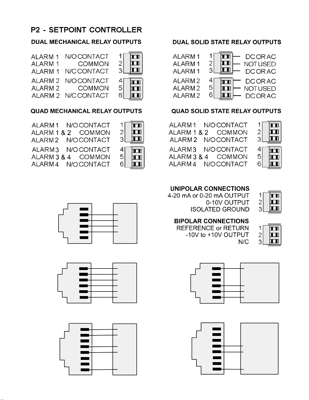
16. DUAL OR QUAD RELAY OUTPUT OPTION
An optional relay board may be installed in the
meter main board at plug position P2, adjacent to
the power supply board. Four board versions are
available: 2 or 4 relays, mechanical or solid state.
Once installed, the relay board is recognized by
the meter software, which will bring up the appropriate menu items. Relay menu items will not be
brought up if no relay board is detected. Menu
selections for relays 3 and 4 will not be brought up
if a dual relay board is detected.
All relay boards offer a choice of operating modes: normally off or on, latched or non-latched,
hysteresis band, deviation band, alarm based on the filtered or unfiltered signal, and selectable
number of readings in alarm zone to cause an alarm.
KEYSTROKES FOR VIEWING & CHANGING SETPOINTS
The
nues to make conversions and performs setpoint control. If the
a setpoint is displayed, conversion stops and the setpoint can be changed. After pressing
you have 30 seconds, or the meter reverts to the normal display. To view setpoints, menu item
Loc1, digit 4, must have been set to 0. To change setpoints, menu item Loc4, digit 6, must
have been set to 0.
300.24
Press
to display Alarm 1
setpoint.
395.00
Press (Alarms)
to display Alarm 2
setpoint.
395.00
Press
to display Alarm 3
setpoint.
(Alarms) key can be used to step through and view setpoints while the meter conti-
(Peak) key is pressed while
Press Alarms
Key
(Alarms)
(Alarms)
_200.00
Current setpoint 1 value blinks, and
Alarm 1 LED indicator lights. Press
to select a digit, which will blink.
_395.00
Current setpoint 2 value blinks, and
Alarm 2 LED indicator lights. Press
to select a digit, which will blink.
_395.00
Current setpoint 3 value blinks, and
Alarm 3 LED indicator lights. Press
to select a digit, which will blink.
Press Digit
Select Key
Press Value Select
Key
_295.00
To change setpoint 1 value,
press
blinking digits.
_305.00
To change setpoint 2 value,
press
blinking digits.
_305.00
To change setpoint 3 value,
press
blinking digits.
to change selected
to change selected
to change selected
,
395.00
Press (Alarms)
to display Alarm 4
setpoint.
300.24 Press (Alarms) again. Meter will reset and display current reading.
_395.00
Current setpoint 4 value blinks, and
Alarm 4 LED indicator lights. Press
to select a digit, which will blink.
37
_305.00
To change setpoint 4 value,
press
blinking digits.
to change selected
Page 38

KEYSTROKES FOR SETPOINT SETUP
If the MENU key does not work, see Section 9 “Enabling & Locking Out Menu Items.”
Press Menu
Select Key
ALSEt
Alarm Setup for
relays 1 & 2 if
detected.
Press
ALSEt is displayed.
until
Press Digit
Select Key
00000
Relay state when
alarm is active.
00000
Alarm latching or non-
latching (auto reset).
00000
Alarm operates at and
above setpoint (active
high) or at and below
setpoint (active low).
Press Value Select
Key
0 Relay 1 on Relay 2 on
1 Relay 1 off Relay 2 on
2 Relay 1 on Relay 2 off
3 Relay 1 off Relay 2 off
0 Alarm 1 auto reset Alarm 2 auto reset
1 Alarm 1 latching Alarm 2 auto reset
2 Alarm 1 auto reset Alarm 2 latching
3 Alarm 1 latching Alarm 2 latching
0 AL1 active high AL2 active high
1 AL1 active low AL2 active high
2 AL1 disabled AL2 active high
3 AL1 active high AL2 active low
4 AL1 active low AL2 active low
5 AL1 disabled AL2 active low
6 AL1 active high AL2 disabled
7 AL1 active low AL2 disabled
8 AL1 disabled AL2 disabled
ALS34
Alarm Setup for
relays 3 & 4 if
detected.
00000
Hysteresis mode or
band deviation mode
00000
Number of consecutive
readings in alarm zone
to cause an alarm.
00000
Relay state when
alarm is active.
00000
Alarm latching or non-
latching (auto reset).
0 AL1 band deviation AL2 band deviation
1 AL1 hysteresis AL2 band deviation
2 AL1 band deviation AL2 hysteresis
3 AL1 hysteresis AL2 hysteresis
4 No deviation or hysteresis in menu.
0 After 1 reading 4 After 16 readings
1 After 2 readings 5 After 32 readings
2 After 4 readings 6 After 64 readings
3 After 8 readings 7 After 128 reading
0 Relay 3 on Relay 4 on
1 Relay 3 off Relay 4 on
2 Relay 3 on Relay 4 off
3 Relay 3 off Relay 4 off
0 Alarm 3 auto reset Alarm 4 auto reset
1 Alarm 3 latching Alarm 4 auto reset
2 Alarm 3 auto reset Alarm 4 latching
3 Alarm 3 latching Alarm 4 latching
38
Page 39

Press Menu
Select Key
Press Digit
Select Key
Press Value Select
Key
ALS34
Alarm Setup for
relays 3 & 4
(continued)
dEU1H
Alarm 1
hysteresis
DEU2H
Alarm 2
hysteresis
00000
Alarm operates at and
above setpoint (active
high) or at and below
setpoint (active low).
00000
Hysteresis mode or
band deviation mode
(see Glossary)
00000
Number of consecutive
readings in alarm zone
to cause an alarm.
0.0000 0.0000 0.0000
0.0000 0.0000
Select digit to flash.
0 AL3 active high AL4 active high
1 AL3 active low AL4 active high
2 AL3 disabled AL4 active high
3 AL3 active high AL4 active low
4 AL3 active low AL4 active low
5 AL3 disabled AL4 active low
6 AL3 active high AL4 disabled
7 AL3 active low AL4 disabled
8 AL3 disabled AL4 disabled
0 AL3 band deviation AL4 band deviation
1 AL3 hysteresis AL4 band deviation
2 AL3 band deviation AL4 hysteresis
3 AL3 hysteresis AL4 hysteresis
0 After 1 reading 4 After 16 readings
1 After 2 readings 5 After 32 readings
2 After 4 readings 6 After 64 readings
3 After 8 readings 7 After 128 reading
Select -9 thru 9 for flashing first digit, 0 thru 9
for other flashing digits. Alarms will activate
above the setpoint by the value entered and
deactivate below the setpoint by the value
entered.
DEU1b
Alarm 1 band
deviation
DEU2b
Alarm 2 band
deviation
dEU3H
Alarm 3
hysteresis
DEU4H
Alarm 4
hysteresis
DEU3b
Alarm 3 band
deviation
DEU4b
Alarm 4 band
deviation
0.0000 0.0000 0.0000
0.0000 0.0000
Select digit to flash.
0.0000 0.0000 0.0000
0.0000 0.0000
Select digit to flash.
0.0000 0.0000 0.0000
0.0000 0.0000
Select digit to flash.
Select -9 thru 9 for flashing first digit, 0 thru 9
for other flashing digits. Alarms will activate
above and below the setpoint by the value
entered and will deactivate in the middle of
the band.
Select -9 thru 9 for flashing first digit, 0 thru 9
for other flashing digits. Alarms will activate
above the setpoint by the value entered and
deactivate below the setpoint by the value
entered.
Select -9 thru 9 for flashing first digit, 0 thru 9
for other flashing digits. Alarms will activate
above and below the setpoint by the value
entered and will deactivate in the middle of
the band.
39
Page 40

17. ANALOG OUTPUT OPTION
An optional analog board may be installed in the meter at rear panel jack position J4, adjacent
to the signal conditioner board. Once installed, this board is recognized by the meter, which
will bring up the appropriate menu items for it. These will not be brought up if an analog output
board is not installed.
The analog output can be a 0-20 mA, 4-20 mA or 0-10V unipolar signal with respect to isolated
ground, or a bipolar -10V to +10V voltage signal with respect to a reference return line.
Unipolar or bipolar operation is selected by a jumper. A unipolar current or voltage output is
selected at the connector. Unipolar 4-20 mA or 0-20 mA current is selected in software.
Unipolar current of voltage: Jumper a
Bipolar -10 to +10 voltage: Jumper b
The low analog output (0 mA, 4 mA, 0V, or -10V) may be set to correspond to any low
displayed reading An Lo. The high analog output (20 mA, 0V or 10V) may be set to correspond to any high displayed reading An Hi. The meter will then apply a straight line fit between
these two end points to provide an analog output scaled to the meter reading.
KEYSTROKES FOR SETUP
If the MENU
Press Menu
Select Key
AnSEt
Analog Output Setup.
Press
is displayed (requires
analog output board).
An Lo
Low displayed value
for 0 mA, 4 mA, 0V, or
-10V output
An Hi.
High displayed value
for 20 mA or 10V out-
put
until AnSEt
key does not work, see Section 9 “Enabling & Locking Out Menu Items.”
___00
Analog output signal
selection.
___00
Analog output filtering.
0.0000 0.0000 0.0000
0.0000 0.0000
Select digit to flash.
0.0000 0.0000 0.0000
0.0000 0.0000
Select digit to flash.
Press Digit Select
Key
40
Press Value Select
Key
0 0-20 mA current output
1 0-10V voltage output
2 4-20 mA current output
3 -10 to +10V voltage output
0 Analog output unfiltered
1 Analog output filtered
Select -9 thru 9 for flashing first
digit, 0 thru 9 for other flashing
digits. Decimal point location is
fixed by dEC.Pt selection.
Select -9 thru 9 for flashing first
digit, 0 thru 9 for other flashing
digits. Decimal point location is
fixed by dEC.Pt selection.
Page 41

18. SERIAL COMMUNICATION OPTIONS
A variety of optional serial communications boards may be connected to the meter main board
at plug position P13 (middle position). These include RS-232, RS-485, RS-485 Modbus, USB,
and USB to RS-485.
Both boards feature dual connectors, which are wired in parallel to allow daisy chaining of
addressable meters. Three serial communication protocols are : Custom ASCII, Modbus RTU,
and Modbus ASCII. Multiple meters on the same serial communication line requires RS485 or
RS485-Modbus boards. The USB to RS485 converter replaces the RS485 board in one of the
meters to provide a direct USB connection to a PC or PLC without an external converter.
LOADING USB AND USB/RS-485 DRIVERS
Using a USB cable with Type A and Type B connectors, connect the meter to the computer.
The computer will display “Found new Hardware” followed by “Welcome to the ‘Found new
Hardware Wizard’ ”. Follow the instructions for installation from a CD
When the installation is complete, use the Device Manager to determine the Com port
number. To get to Device Manger, go to Control Panel, click on System, click on Hardware tab
and then click on Device Manager. Go down the device list and click on Ports (COM & LPT)
and USB serial port (com #). Note the com port # for use with communications to your IPM
meter, and exit Control Panel
If you need to change the Com port, right-click on USB serial port (com #), then click on
Properties, Port settings and Advanced. Change the port to the desired number and click OK,
then exit Control Panel.
BOARD SETUP VIA JUMPERS
USB Board No jumpers required
RS232 Board
g - Normal operation.
h - Slave display operation to RS232 from another meter.
J - Pull-up resistor on RTS line.
RS-232
RJ11
g
h
j
Note: The board is shipped with jumpers g and j installed.
RS232 Board Rev J
RJ11
e - Normal operation.
f - Slave display operation to RS232 from another meter.
g - Pull-up resistor on RTS line.
Note: The board is shipped with jumpers e and g installed
RS-232
g
f
e
232
d
RS485 and RS485-Modbus Boards
Full Duplex Operation
c
e
f
a
b
RJ45
J
b & e - Bias jumpers should be installed on 1 board.
a & d - Installed on last meter in long cable run.
41
RJ45
Modbus
Page 42

Half Duplex Operation
b & e - bias jumpers installed on 1 board.
c & f - installed for half duplex operation.
a - installed on last meter in line with long cable runs.
Note: The boards are shipped with no jumpers installed.
RS-485
a
b
e
c
d
f
RJ11
RJ11
RS485 Rev J and USB/RS485 Boards
Full Duplex Operation
b & d - Installed on last meter in long cable run.
Half Duplex Operation
a & c - Installed for half duplex operation.
d - Installed on last meter in line with long cable runs.
Note: The boards are shipped with no jumpers installed.
KEYSTROKES FOR SETUP
If the MENU
key does not work, see Section 9 “Enabling & Locking Out Menu Items.”
Press Menu
Select Key
Press Digit Select
Key
a bc d
RJ11
RJ11
RS-485
USB/RS-485
a bc d
J
USB
RJ11
232
Press Value Select
Key
.SEr 1.
Fixed Parameters:
No parity
8 data bits
1 stop bit
__000
Output filtering
__000U
Baud rate
__000U
Output update rate
0 Send unfiltered signal
1 Send filtered signal
0 300 baud
1 600 baud
2 1200 baud
3 2400 baud
4 4800 baud
5 9600 baud
6 19200 baud
60 Hz 50 Hz
0 Line frequency Line frequency
1 0.28 sec 0.34 sec
2 0.57 sec 0.68 sec
3 1.1 sec 1.4 sec
4 2.3 sec 2.7 sec
5 4.5 sec 5.4 sec
6 9.1 sec 10.9 sec
7 18.1 sec 21.8 sec
8 36.6 sec 43.5 sec
9 72.5 sec 97 sec
42
Page 43

Press Menu
Select Key
Press Digit Select
Key
Press Value Select
Key
.SEr 2.
Serial Setup 2
.SEr 3.
Serial Setup 3
_0000U
Line feed
_0000U
Alarm data with readings
_0000U
Control of data output
_0000U
Meter address with Custom
ASCII protocol
00000U
Half or full duplex
00000U
Special start & stop char.
00000U
RTS mode
00000U
Termination characters
0 No line feed after carriage return
1 Line feed after carriage return
0 No alarm data
1 Alarm data with reading
0 Continuous data output
1 Data output on ASCII command only
Select 1 thru F for addresses 1 thru 15.
Select 0. thru F. (with decimal point) for
addresses 16 thru 31.
0 Full duplex
1 Half duplex
0 Standard continuous mode
1 Special start & stop characters
0 Normal RTS
1 Single transmission
0 Only at end of all items
1 At end of each item
.SEr 3.
Serial Setup 3
(continued)
SEr 4.
Serial Setup 4.
_Addr
Modbus Address.
Appears only if a
Modbus protocol is
selected.
00000U
Data sent in continuous
mode
__000U
Modbus ASCII gap timeout
__000U
Serial protocol
__000U
Parity
__000 __000 __000
Select digit to flash.
0 Reading
1 Peak
2 Valley
3 Reading + peak
4 Reading + valley
5 Reading + peak + valley
0 1 sec
1 3 sec
2 5 sec
3 10 sec
0 Custom ASCII
1 Modbus RTU
2 Modbus ASCII
0 None, 2 or more stop bits
1 Odd, 1 or more stop bits
2 Even, 1 or more stop bits
__247
Select 0 through 9 for flashing digit.
Address range is 1 to 247.
43
Page 44

19. TEDS INTERFACE
U
pon power up, a TEDS enabled IPM490 or IPM500 meter will display a sequence of "3333",
"2222", and "1111" followed by the firmware revision, alerting the user of TEDS capability.
Ensure that the proper connections are made from pins 5 and 6 of the TEDS connector to the
DB-9 converter PCB before plugging in a TEDS enabled sensor, as described in Section 4.
Once the sensor is connected, the meter will display the manufacturer's ID and TEDS template
number, followed by an automatic reset. If the sensor contains meter analog output or decimal
point settings, the meter will automatically configure these settings.
TEDS MENU SELECTIONS
The following menu selections must be entered before retrieving TEDS information from your
TEDS enabled sensor. The meter must be configured for 2-point calibration before the sensor
is connected; otherwise analog output settings will not be set up properly.
Press Menu
Select Key
SEtuP
Press key until
SEtuP is displayed.
SEr 1.
Press key until
SEr 1 is displayed.
SEr 2.
Press key until
SEr 2 is displayed.
SEr 3.
Press
SEr 3 is displayed.
key until
Press Digit
Select Key
00000
Press
th
4
digit to flash.
000U
Press
to flash.
0000U
Press
to flash.
00000U
Press
to flash.
to select the
to select digit
to select digit
to select digit
Press Value Select
Key
00010
Press
2 points scaling method.
150 Set digit 3 to 1 for filtered signal.
150 Set digit 4 to 5 for 9600 baud.
150 Set digit 5 to 0 for 60/s output rate.
0000 Set digit 2 to 0 for no line feed.
0000 Set digit 3 to 0 for no alarm data.
0000 Set digit 4 to 0 for continuous
0001 Set digit 5 to 1 thru F for addresses
00000 Set digit 1 to 0 for full duplex.
00000 Set digit 2 to 0 for standard
00000 Set digit 3 to 0 for normal RTS.
00000 Set digit 4 to 0 for termination cha-
00001 Set digit 5 to 0 for data readings in
to set digit 4 to 1 for coordinates of
output.
1 thru 15 or to 0. thru F. (with deci-
mal point) for addresses 16 thru 31.
continuous output.
racters only at end of all items.
continuous mode.
44
Page 45

TEDS INTERFACE WIRING
TEDS DATA
TEDS GROUND
ISOLATED GROUND
RTS
RX
TX
Meter
6
6
6
6
6
6
6
6
6
6
6
6
6
6
6
6
6
6
6
6
6
6
6
6
6
6
6
6
6
6
6
6
6
6
6
6
6
6
6
6
6
6
6
6
6
6
6
6
6
6
6
6
6
6
6
6
6
6
6
6
6
6
6
6
6
6
6
6
6
6
6
6
6
6
6
6
6
6
6
6
6
6
6
6
6
6
6
6
6
6
6
6
6
6
6
6
6
6
6
6
6
6
6
6
6
6
6
6
6
6
6
6
6
6
6
6
6
6
6
6
6
6
6
6
6
6
6
6
6
6
6
6
6
6
6
6
6
6
6
6
6
6
6
6
6
6
6
6
6
6
6
6
6
6
6
6
6
6
6
6
6
6
6
6
6
6
6
6
6
6
6
6
6
6
6
6
6
6
6
6
6
6
6
6
6
6
6
6
6
6
6
6
6
6
6
6
6
6
6
6
6
6
6
6
6
6
6
6
6
6
6
6
6
6
6
6
5
5
5
5
5
5
5
5
5
5
5
5
5
5
5
5
5
5
5
5
5
5
5
5
5
5
5
5
5
5
5
5
5
5
5
5
5
5
5
5
5
5
5
5
5
5
5
5
5
5
5
5
5
5
5
5
5
5
5
5
5
5
5
5
5
5
5
5
5
5
5
5
5
5
5
5
5
5
5
5
5
5
5
5
5
5
5
5
5
5
5
5
5
5
5
5
5
5
5
5
5
5
5
5
5
5
5
5
5
5
5
5
5
5
5
5
5
5
5
5
5
5
5
5
5
5
5
5
5
5
5
5
5
5
5
5
5
5
5
5
5
5
5
5
5
5
5
5
5
5
5
5
5
5
5
5
5
5
5
5
5
5
5
5
5
5
5
5
5
5
5
5
5
5
5
5
5
5
5
5
5
5
5
5
5
5
5
5
5
5
5
5
5
5
5
5
5
5
5
5
5
5
5
5
5
5
5
5
5
5
5
5
5
5
5
5
4
4
4
4
4
4
4
4
4
4
4
4
4
4
4
4
4
4
4
4
4
4
4
4
4
4
4
4
4
4
4
4
4
4
4
4
4
4
4
4
4
4
4
4
4
4
4
4
4
4
4
4
4
4
4
4
4
4
4
4
4
4
4
4
4
4
4
4
4
4
4
4
4
4
4
4
4
4
4
4
4
4
4
4
4
4
4
4
4
4
4
4
4
4
4
4
4
4
4
4
4
4
4
4
4
4
4
4
4
4
4
4
4
4
4
4
4
4
4
4
4
4
4
4
4
4
4
4
4
4
4
4
4
4
4
4
4
4
4
4
4
4
4
4
4
4
4
4
4
4
4
4
4
4
4
4
4
4
4
4
4
4
4
4
4
4
4
4
4
4
4
4
4
4
4
4
4
4
4
4
4
4
4
4
4
4
4
4
4
4
4
4
4
4
4
4
4
4
4
4
4
4
4
4
4
4
4
4
4
4
4
4
4
4
4
4
3
3
3
3
3
3
3
3
3
3
3
3
3
3
3
3
3
3
3
3
3
3
3
3
3
3
3
3
3
3
3
3
3
3
3
3
3
3
3
3
3
3
3
3
3
3
3
3
3
3
3
3
3
3
3
3
3
3
3
3
3
3
3
3
3
3
3
3
3
3
3
3
3
3
3
3
3
3
3
3
3
3
3
3
3
3
3
3
3
3
3
3
3
3
3
3
3
3
3
3
3
3
3
3
3
3
3
3
3
3
3
3
3
3
3
3
3
3
3
3
3
3
3
3
3
3
3
3
3
3
3
3
3
3
3
3
3
3
3
3
3
3
3
3
3
3
3
3
3
3
3
3
3
3
3
3
3
3
3
3
3
3
3
3
3
3
3
3
3
3
3
3
3
3
3
3
3
3
3
3
3
3
3
3
3
3
3
3
3
3
3
3
3
3
3
3
3
3
3
3
3
3
3
3
3
3
3
3
3
3
3
3
3
3
3
3
2
2
2
2
2
2
2
2
2
2
2
2
2
2
2
2
2
2
2
2
2
2
2
2
2
2
2
2
2
2
2
2
2
2
2
2
2
2
2
2
2
2
2
2
2
2
2
2
2
2
2
2
2
2
2
2
2
2
2
2
2
2
2
2
2
2
2
2
2
2
2
2
2
2
2
2
2
2
2
2
2
2
2
2
2
2
2
2
2
2
2
2
2
2
2
2
2
2
2
2
2
2
2
2
2
2
2
2
2
2
2
2
2
2
2
2
2
2
2
2
2
2
2
2
2
2
2
2
2
2
2
2
2
2
2
2
2
2
2
2
2
2
2
2
2
2
2
2
2
2
2
2
2
2
2
2
2
2
2
2
2
2
2
2
2
2
2
2
2
2
2
2
2
2
2
2
2
2
2
2
2
2
2
2
2
2
2
2
2
2
2
2
2
2
2
2
2
2
2
2
2
2
2
2
2
2
2
2
2
2
2
2
2
2
2
2
1
1
1
1
1
1
1
1
1
1
1
1
1
1
1
1
1
1
1
1
1
1
1
1
1
1
1
1
1
1
1
1
1
1
1
1
1
1
1
1
1
1
1
1
1
1
1
1
1
1
1
1
1
1
1
1
1
1
1
1
1
1
1
1
1
1
1
1
1
1
1
1
1
1
1
1
1
1
1
1
1
1
1
1
1
1
1
1
1
1
1
1
1
1
1
1
1
1
1
1
1
1
1
1
1
1
1
1
1
1
1
1
1
1
1
1
1
1
1
1
1
1
1
1
1
1
1
1
1
1
1
1
1
1
1
1
1
1
1
1
1
1
1
1
1
1
1
1
1
1
1
1
1
1
1
1
1
1
1
1
1
1
1
1
1
1
1
1
1
1
1
1
1
1
1
1
1
1
1
1
1
1
1
1
1
1
1
1
1
1
1
1
1
1
1
1
1
1
1
1
1
1
1
1
1
1
1
1
1
1
1
1
1
1
1
1
Sensor
DATA
GROUND
Computer
GROUND
RTS
TRANSMIT
RECEIVE
Notes:
• Do not connect RS-232 pins 1-4 if using a USB connection.
• Do not connect TEDS ground to isolated ground.
• RTS line may have to be disconnected for certain software applications. RTS pin cannot be
disconnected when using a USB connection.
• RTS line must be un-asserted through software for normal USB operation. Please see your
software manual. If software does not allow un-assertion of RTS line, you must use RS232
without RTS connected. The meters use RTS to gain control of the TEDS card.
45
Page 46

20. EXCITATION OUTPUT & POWER SUPPLY
Three isolated transducer excitation output levels are available from the power supply board.
These are selectable via jumpers b, c, d, e, f in the upper right of the board, as illustrated.
In addition, the board provides three jumper positions for special features. The same jumper
locations apply to the universal power supply (95-240 Vac ±10%) and to the low voltage power
supply (12-30 Vac or 10-48 Vdc).
Excitation output Jumper locations
5 Vdc ±5%, 100 mA max
10 Vdc ±5%, 120 mA max
24 Vdc ±5%, 50 mA max
SELECTION OF OTHER JUMPERS
Jumper a - Front panel menu lockout, locked when installed. (See Section 9)
Jumper g - Provides +5V power output at P1-4 when installed.
Jumper h - Connects "Control Input 2" to P1-4 when installed.
b, d, e
b, d, f
c
46
Page 47

21. METER CALIBRATION
All analog input and analog output ranges of the meter have been digitally calibrated at the
factory prior to shipment using calibration equipment certified to NIST standards. Calibration
constants are stored digitally in non-volatile memory in EEPROM on the signal conditioner
board and analog output board. As a result, these boards may be mixed and interchanged
without requiring meter recalibration. Digital calibration eliminates much of circuitry that would
be associated with analog calibration, providing superior long term accuracy and stability.
If recalibration is required, the meter may be returned to the factory .
47
Page 48

22. SPECIFICATIONS
Meter Display
Type ....................................5 LED, 7-segment, 14.2mm (.56") high digits & 3 LED indicators
Color....................................................................................................................Red or green
Range.................................................................... -99999 to +99999 and -99990 to +99990
A to D Conversion
Technique (Pat.5,262,780)........................................................................ Concurrent Slope
Read Rate ...............................................................60/s for 60 Hz NMR, 50/s for 50 Hz NMR
Output Update Rate .....................................................................56/s at 60 Hz, 47/s at 50 Hz
Display Update Rate .....................................................................3.5/s at 60 Hz, 3/s at 50 Hz
Noise Rejection
CMV from DC to 60 Hz................................................................................Withstand 250Vac
Dielectric strength....................................................... 3.5 kV ac for 5 sec, 2.3 kV ac for 1 min
CMR from DC to 60 Hz ................................................................................................ 130 dB
NMR at 50/60 Hz...............................................................90 dB with minimum digital filtering
Control Inputs (CMOS/TTL levels, logic 0 = tied to digital ground, logic 1 = open)
TM
/ Hold input ..........................................................................Logic 0 holds display and outputs
/ Peak or Valley input .........................................................Logic 0 displays peak/valley value
/ Tare input ......................................................................... Logic 0 offsets input value to zero
/ Tare Reset .........................................................................Logic 0 resets Tare value to zero
/ Reset input ........................................................................ Logic 0 resets all meter functions
/ Function Reset input .................................................Logic 0 resets peak values and alarms
/ Decimal Point input .....................Overrides internal DP selections and controls DP position
/ Display Blank input.....................................................................Logic 0 shuts off the display
Power Requirements
Input Voltage rating (standard)...............95-240 Vac ±10% or 90-300 Vdc (DC range not UL)
Input Voltage rating (low voltage option) ............................................12-30 Vac or 10-48 Vdc
Power Line Frequency .................................................................................DC and 47-63 Hz
Power Consumption, Max ........................................................................................... 5 Watts
Excitation Outputs
Voltage & Current Levels (jumper selectable) .................................. 5 Vdc ±5%, 100 mA max
....................................................................................................... 10 Vdc ±5%, 120 mA max
........................................................................................................ 24 Vdc ± 5%, 40 mA max
Excitation Output Ripple.....................................................................................100 mVp max
Isolation from power and outputs ............................................................................... 250 Vac
Insulation dielectric strength to power and outputs..... 3.5 kV ac for 5 sec, 2.3 kV ac for 1 min
Isolation to signal common........................................................................................... 50 Vdc
48
Page 49

Input Types, Ranges, Resolution, Error at 25°C
DC Volts
Range Resol. Resistance Error
200.00 mV
2.0000 V
20.000 V
200.00 V
300.0 V
DC Amps
Range Resol. Resistance Error
2.0000 mA
20.000 mA
200.00 mA
5.000 A
True RMS Volts (0% to 100% of Full Scale,
0 Hz and 10 Hz to 10 kHz, crest factor 3.0)
Range Resol. Resistance Error
200.00 mV
2.0000 V
20.000 V
200.00 V
600.0 V 100 mV 1 MΩ 2V
True RMS Amps (0% to 100% of Full Scale,
0 Hz and 10 Hz to 10 kHz, crest factor 3.0)
Range Resol. Resistance Error
10 µV
100 µV
1 mV
10 mV
100 mV
0.1 µA
1 µA
10 µA
1 mA
10 µV
100 µV
1 mV
10 mV
1 GΩ
1 GΩ
10 MΩ
10 MΩ
10 MΩ
100 Ω
10 Ω
1 Ω
0.01 Ω
22 MΩ
22 MΩ
1 MΩ
1 MΩ
0.01%
of FS
±2 cts
0.01%
of FS
±2 cts
0.1%
of FS
Thermocouple (0.1°, 1° resolution)
Type Range Error
J
K
T
E
N
S
R
RTD (0.01°, 0.1°, 1° resolution)
Type Range Error
Pt 100Ω
.00385
Pt 100Ω
.003925
-210 to 760°C
-347to 1400°F
-244 to 1372°C
-408to 2501°F
0 to 400°C
-257 to 0°C
32 to 752°F
-430 to 32°F
-240 to 1000°C
-400 to 1830°F
-245 to 1300°C
-410 to 2370°F
-46 to +68°C
-51 to +213°F
-45 to 1768°C
-49 to 3214°F
-202 to 850°C
-331 to 1562°F
-202 to 631°C
-331 to 1168°F
.01% FS ±0.09°C
.01% FS ±0.16°F
.01% FS ±0.10°C
.01% FS ±0.17°F
.01% FS ±0.03°C
.01% FS ±0.20°C
.01% FS ±0.05°F
.01% FS ±0.36°F
.01% FS ±0.18°C
.01% FS ±0.32°F
.01% FS ±0.10°C
.01% FS ±0.17°F
.01% FS ±0.12°C
.01% FS ±0.22°F
.01% FS ±0.17°C
.01% FS ±0.31°F
.01% FS ±0.03°C
.01% FS ±0.05°F
.01% FS ±0.04°C
.01% FS ±0.07°F
2.0000 mA
20.000 mA
200.00 mA
5.000 A 1 mA 0.01 Ω 20 mA
Resistance Measurement
Range Resolution Error
0-20.000Ω
0-200.00Ω
0-2000.0Ω
0-20000 Ω
0-200.00 kΩ
0.1 µA
1 µA
10 µA
1 mΩ
10 mΩ
100 mΩ
1 Ω
10 Ω
100 Ω
10 Ω
1 Ω
0.1%
of FS
0.01%
of FS
±2 cts
Ni 120Ω
.00672
Cu 10Ω
.00427
Ratio, Potentiometer Follower, Strain
Range Resol. Resistance Error
200.00 mV
2.0000 V
20.000 V
49
-80 to 260°C
-112 to 500°F
-97 to 260°C
-143 to 500°F
10 µV
100 µV
1 mV
.01% FS ±0.05°C
.01% FS ±0.09°F
.01% FS ±0.05°C
.01% FS ±0.09°F
1 GΩ
1 GΩ
1 MΩ
0.01%
of FS
±2 cts
Page 50

Load Cell Input
Range Resolution Resistance Zero Range Span Range Error
20.000 mV
50.000 mV
100.00 mV
250.00 mV
500.00 mV
Thermocouple Accuracy
Span Tempco .........................................................................................0.003% of reading/°C
............................................................................... 0.0015% of reading/°C for load cell meter
Zero Tempco............................................................................................................ 0.2 µV/°C
Reference Junction Accuracy .....................................................................1°C, 10°C to 40°C
Dual & Quad Relay Options
Power to Relay Option ................................................................................Powered by meter
Setpoint Setup....................................................... Via front panel pushbuttons or RS232/485
Update Rate .................................................................................56/s at 60 Hz, 47/s at 50 Hz
Response to input signal (min)..................................................................Display update rate
Input Signal (selectable)........................................................Filtered or unfiltered input signal
Actuation Modes (selectable) ...... Above or below setpoint, latching or non-latching, disabled
Output Time Delay (selectable).................................................................... 1 to 128 readings
Front Panel Enable / Lockout Modes (selectable)................1) Display and change setpoints
...................................................................................2) Display but do not change setpoints
..................................................................................3) Neither display nor change setpoints
Alarm Status Indication ..........................................................................2 or 4 red LED lamps
Status Indication Setup (selectable) .......................Lit when output is ON or OFF, or disabled
1 µV
2.5 µV
5 µV
12.5 µV
25 µV
1 GΩ
-99999 to
99999
0 to ±99,999
0.01% of FS
±2 cts
Form C, SPDT Relay Output:
AC Rating..........................................................................................................8A @ 240 Vac
DC Rating........................................................................................................... 8A @ 24 Vdc
Isolation rating between signal common and contacts ............................................... 250 Vac
Insulation dielectric strength between signal common and contacts ........................................
................................................................................... 3.5 kV ac for 5 sec, 2.3 kV ac for 1 min
50
Page 51

Form A, SPST Solid State Relay Output:
AC Rating..................................................................................................130 mA @ 140 Vac
DC Rating..................................................................................................130 mA @ 180 Vdc
Isolation rating between signal common and contacts ............................................... 250V ac
Insulation dielectric strength between signal common and contacts ........................................
................................................................................... 3.5 kV ac for 5 sec, 2.3 kV ac for 1 min
Analog Output Option
Power to Analog Output Option...................................................................Powered by meter
Output Levels ..............................................................0-20 mA, 4-20 mA, 0-10V, -10 to +10V
Voltage Compliance, 0-20 mA Output .................................................. 12V (0-600 Ohm load)
Current Compliance, 0-10V, -10 to +10V Output.......................2 mA (5 kOhm or higher load)
Accuracy ..........................................Meter input accuracy ±0.02% of full scale analog output
Resolution ...........................................................................................16 bit (1 part in 65,536)
Response Time ....................................................................................... 50/60Hz update rate
Scaling of Reading for Zero Output............................................................-99,999 to +99,999
Scaling of Reading for Full Scale Output................................................... -99,999 to +99,999
Isolation rating between signal common and analog output....................................... 250V ac
Insulation dielectric strength between signal common and analog output................................
................................................................................... 3.5 kV ac for 5 sec, 2.3 kV ac for 1 min
Serial Interface Option (USB, RS232, RS485, RS485-Modbus boards)
Output Types................................................................RS232, RS485, RS485-Modbus, USB
Power to Interface Option............................................................................Powered by meter
RS485 Wiring ...............................................................................................Half or full duplex
Baud Rates ............................................................ 300, 600, 1200, 2400, 4800, 9600, 19200
Serial Protocols ............................. Custom ASCII, Modbus RTU, Modbus ASCII (selectable)
Signal Levels.............................................................................. Meet RS232, RS485 or USB
Connectors....... USB, Single RJ11 (RS232), two RJ11 (RS485), two RJ45 (RS485-Modbus)
Isolation rating between signal common and serial I/O .............................................. 250V ac
Insulation dielectric strength between signal common and serial I/O .......................................
................................................................................... 3.5 kV ac for 5 sec, 2.3 kV ac for 1 min
Environmental
Operating Temperature .........................................................................................0°C to 55°C
Storage Temperature ........................................................................................ -40°C to 85°C
Relative Humidity ......................................................95% from 0°C to 40°C, non-condensing
Case............................ NEMA-4X (IP65) from front when panel mounted (not verified for UL)
Shock ........................................................................... 10 G at 1 kHz, applied in X, Y, Z axes
Vibration ............................................. 15 Hz to 150 Hz, 1 mm to 2 mm amplitude, 20 G max.
- 51 -
Page 52

23. GLOSSARY OF TERMS
Adaptive Filter Threshold
A threshold which causes an adaptive moving average filter to be reset to the
latest reading when the accumulated difference between individual readings
and the filtered reading exceeds that threshold. Adaptive moving average
filtering allows a meter to respond rapidly to actual changes in signal while
filtering out normal noise. The accumulated difference is also reset to zero
when the latest reading has a different polarity than the filtered reading. A low
adaptive filter threshold is normally selected. A high
selected if the signal has large transients.
Alarm, Latched
An alarm which stays actuated until reset.
Latched alarms can shut down machinery or
a process when an operating limit has been
exceeded, or maintain an alarm condition
until acknowledged by an operator.
Alarm, Non-latched
An alarm which changes state automatically
when the reading rises above a specified limit
and changes back automatically when the
reading falls below a limit.
filter threshold should be
Autofilter A selectable digital filter mode which auto-
matically selects an appropriate moving average filter time constant from 0.08 sec to 9.6
sec for the encountered noise condition.
Auto-tare A selectable meter operating mode, where
the first reading following power-on or meter reset is used to zero the display.
Further readings are then relative to this new zero.
Batch Average Filter
A digital filter mode which averages 16 readings and then displays the average.
Readings are taken at 60/sec with 60 Hz power and 50/sec with 50 Hz power.
Counts The reading displayed on the panel meter ignoring the decimal point.
Custom ASCII Protocol
A simplified, short protocol for use with these panel meters. It allows 31 digital
addresses. Not an industry-standard protocol, like the more complex Modbus
protocol, which is also offered with the meters.
Deviation Band
A band in counts which controls relay action symmetrically around a setpoint.
The relay actuates when the reading falls within the deviation band, and deactuates when the reading falls outside. A limit (e.g., 50 counts) is set up
around both sides of the setpoint to create a deviation band (e.g., 100 counts).
Setting up a passband around a setpoint is often used for component testing.
- 52 -
Page 53

Deviation limits are programmed by entering
menu item dEU1b for Alarm 1 and dEU2b for
Alarm 2. The deviation band will be equal to
two limits.
Display Blank A rear panel input which blanks the display
when the input is tied to logic ground by a
switch or 0V is applied (logic level true). The
meter display will light when the input is
open or is held at +5V (logic level false).
Extended Meter
A digital panel meter with an enhanced microcomputer that provides added
capabilities, specifically linearization of nonlinear inputs and display of rate of
change from successive readings.
Full Scale The maximum input signal range for which the meter has been configured. For
example, the most sensitive full scale for the load cell meter is ±20 mV (signal
range from -20 mV to +20 mV).
Function Reset
A rear panel control input which resets Peak, Valley and any latched alarms
when the input is tied to logic ground by a switch or 0V is applied (logic level
true). To reset the value again, the input must be open or 5V applied (logic
level false) and then set low.
Ground Loop A closed conductive path in external ground wiring that allows stray currents to
flow in ground wiring, creating ground noise. The meters in this manual
minimize ground loop problems by mutually isolating the grounds associated
with meter power, signal input, and all output and communication options.
Jumper A push-on component which provides a short between two adjacent posts on a
circuit board. Jumpers are used to configure signal conditioner boards for
specific signal types and full scale ranges, and to configure power supply and
communications boards for various modes of operation. Unused jumpers are
stored by pushing one side over an unused post.
Hysteresis Band
A band which controls relay action sym-
metrically around a setpoint. The relay
closes (or opens) when the reading goes
above the setpoint plus one hysteresis limit,
and opens (or closes) when the reading
falls below the setpoint less one hysteresis
limit. A narrow hysteresis band is often
used to minimize relay chatter around a
setpoint due to electrical noise or signal
feedback caused by load switching. A wide
hysteresis band can be used for control applications, such as turning on a fill
pump when the tank level has reached a lower limit and shutting off the pump
when the tank level has reached an upper limit. The hysteresis band will be
equal to two hysteresis limits.
- 53 -
Page 54

Menu Mode The meter programming mode used for input and range selection, meter setup,
and meter configuration. Entered into from the Run mode by pressing the
MENU key. The Menu mode can be locked out completely by a jumper.
Meter Hold A rear panel input which freezes the meter display and all meter outputs while
that input is tied to logic ground by a switch or is held at 0V (logic level true).
The meter will resume operation when the input is allowed to float or is held at
+5V (logic level false).
Modbus An industry-standard serial communications protocol which allows devices by
different manufacturers to be digitally addressed by a PC on the same communication line, with up to 247 digital addresses. More complex than the
Custom ASCII protocol, which is also supported by these meters.
Moving Average Filter
A digital filter mode which displays a weighting moving average of readings.
Readings are taken at 60/sec with 60 Hz power and 50/sec with 50 Hz power.
Display update rates remain 3.5/sec with 60 Hz power and 3.0/sec with 50 Hz
power. There are eight moving average modes:
Old average x 1/2 + new reading x 1/2 (equivalent to 0.08 sec RC time constant).
Old average x 3/4 + new reading x 1/4 (equivalent to 0.15 sec RC time constant).
Old average x 7/8 + new reading x 1/8 (equivalent to 0.3 sec RC time constant).
Old average x 15/16 + new reading x 1/16 (equivalent to 0.6 sec RC time constant).
Old average x 31/32 + new reading x 1/32 (equivalent to 1.2 sec RC time constant).
Old average x 63/64 + new reading x 1/64 (equivalent to 2.4 sec RC time constant).
Old avg. x 127/128 + new reading x 1/128 (equivalent to 4.8 sec RC time constant).
Old avg. x 255/256 + new reading x 1/256 (equivalent to 9.6 sec RC time constant).
Offset A constant adder used for the displayed reading. This is the term b in the
straight line formula y = mx + b, where y is the displayed reading in counts, m
is the scale factor, x is the measured reading in counts, and b is the offset. For
direct readout in (milli)volts or (milli)amps, offset is 0.
Peak Display The maximum (or most positive) reading since that maximum was last reset.
Reset can be via the meter front panel, an external input, or a software
command. The displayed value can reflect the filtered or unfiltered readings.
Process Signal
A signal whose display requires setup of scale and offset settings for display in
engineering units. A classical process signal is 4-20 mA, where the 4 mA and
20 mA end points can each correspond to a desired meter reading.
Rate of Change Meter
A configuration mode of the Extended meter which allows the display of rate
based on successive readings. The conversion to engineering units is achieved
with the combination of a multiplier from 0.1 to 10,000 and a scale factor.
Reading The value displayed by the meter. “Taking a reading” is the action of the meter
to make an analog-to-digital conversion. Readings are taken at 60/sec with 60
Hz power or 50/sec with 50 Hz power, and are displayed with an update rate of
3.5/sec with 60 Hz power or 3.0/sec with 50 Hz power.
- 54 -
Page 55

Remote Display
A display mode which allows the meter to serve as a remote display to another
meter when connected to it by a 4-wire phone cord. Also allows the meter to
transmit raw measurement data to a computer and then display processed data
from the computer. A serial communications option board is required in the
meter. If such a board is not installed or no serial data is received, the meter
displays rESEt.
Reset There are three types of Reset:
Peak and Valley Reset. Achieved by simultaneously pressing the RESET
and PEAK keys.
Latched Alarm Reset. Achieved by simultaneously pressing the RESET and
ALARMS keys.
Meter Reset. Causes the meter to reinitialize and take a tare reading when
set up for auto-tare. Achieved powering up the meter, by pressing the
RESET and MENU keys simultaneously, stepping through all top-level
menu choices, grounding a rear panel connector, or supplying an ASCII
command. rESEt is displayed briefly.
RS485 Half Duplex
Serial communications implemented with two wires, allowing data transmission
in both directions, but not simultaneously.
RS485 Full Duplex
Serial communications implemented with four wires, allowing data transmission
in two directions simultaneously.
Run Mode The normal operating mode of the meter, where readings are taken, as
opposed to the menu mode.
Scale A constant multiplier used to go from A/D
converter counts to displayed counts. This is
the slope term m in the straight line formula y
= mx + b, where y is the displayed reading in
counts, m is the scale factor, x is the
measured reading in counts, and b is the
offset. For direct readout in (milli)volts or
(milli)amps, scale is 1.
Scaling The process of setting scale and offset so
that the meter reads properly in engineering
units (such as psi).
Scaling, Coordinates of 2 Points Method
A scaling method where four numbers are entered manually: low input, desired
reading at low input; high input, and desired reading at high input. The meter
then applies a straight line fit. The decimal point is set by the separate dEC.Pt
menu item.
Scaling, Scale and Offset Method
A scaling method where scale and offset are entered manually.
- 55 -
Page 56

Scaling, Reading Coordinates of 2 Points Method
A scaling method, where the low and high input values are determined from
actual signals. A known low signal is first applied to the meter, such as the
output of a pressure transducer at zero pressure. That signal is captured as the
low input value, and the desired low reading is entered. A known high signal is
then applied, such the output of a transducer for a know weight or pressure.
That signal is captured as the high input value, and the desired high reading is
entered. The meter then applies straight line fit. This scaling method has the
advantage of calibrating the transducer and meter as a system. The actual
voltage or current at either point does not need to be known. The decimal point
is set by the separate dEC.Pt menu item.
Setpoint A value compared to the reading to determine the state of a relay. Term often
used interchangeably with “alarm setpoint.” The relay action can by latching or
non-latching, utilize a hysteresis band, or utilize a deviation band. Hysteresis
bands and deviation bands are specified by two symmetrical limits around the
setpoint.
Span The number of counts corresponding to a given signal range.
Tare A rear panel input which causes the display to be set to zero when the input is
momentarily tied to logic ground by a switch or is held at 0V (logic level true).
When the input is allowed to float or is held at +5V (logic level false), the meter
displays readings relative to this new zero. A common application is in
weighing, where an external Tare button is pressed to read the weight of an
empty scale (tare), and tare is then automatically subtracted as a constant from
gross weight for display of net weight. Tare can also be used for other applications where a reading relative to starting point is desired.
Valley Display
The minimum (or most negative) reading since that minimum was last reset.
Reset can be via the meter front panel, an external input, or a software
command. The displayed value can reflect the filtered or unfiltered readings.
Zero When used with process meters, zero is an adjustment so that a given low
transducer output reads zero on the meter. Zero is adjusted by programming
offset.
Copyright 1993-2009 FUTEK Advanced Sensor Technology REV 11/09/09
- 56 -
 Loading...