

Page 1
10 Thomas, Irvine, CA 92618 USA
Tel: (949) 465-0900
Fax: (949) 465-0905
Toll Free: (800) 23 FUTEK
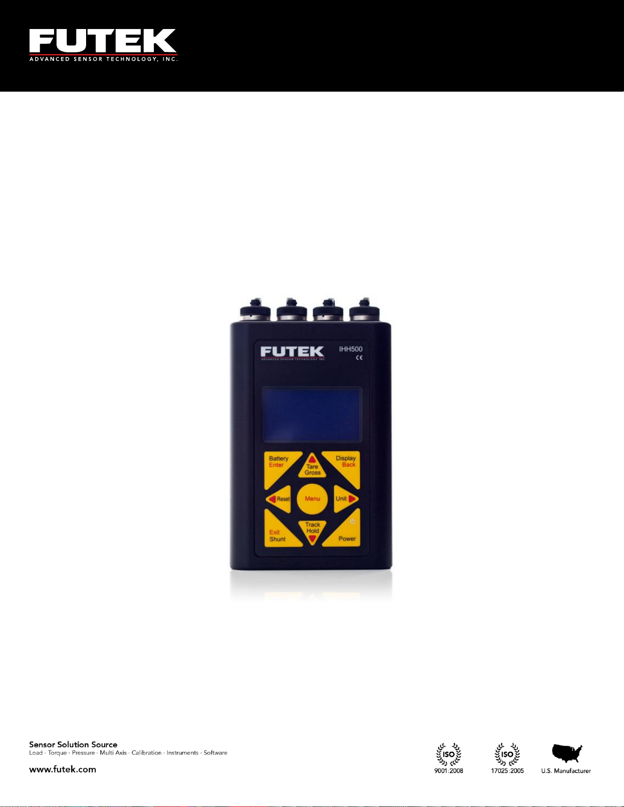
IHH500 Product Manual
Page 2

10 Thomas, Irvine, CA 92618 USA
Tel: (949) 465-0900
Fax: (949) 465-0905
Toll Free: (800) 23 FUTEK
Table of Contents
1 Receiving & Unpacking ................................................................................................................................ - 5 -
1.1 Unpacking ................................................................................................................................................. - 5 -
1.2 Storage ........................................................................................................................................................ - 5 -
1.3 Accessories Supplied ............................................................................................................................... - 5 -
1.4 Optional Accessories ................................................................................................................................ - 5 -
2 Safety Considerations & Care for Your Device ........................................................................................ - 6 -
3 Important Information for IHH500 ............................................................................................................ - 7 -
3.1 Performance .............................................................................................................................................. - 7 -
3.2 Product Introduction................................................................................................................................ - 7 -
4 Connector & Wiring Diagram ..................................................................................................................... - 9 -
5 Features ......................................................................................................................................................... - 10 -
5.1 IHH500 Overview .................................................................................................................................. - 10 -
5.2 IHH500 Structure .................................................................................................................................... - 14 -
5.3 Main Display ........................................................................................................................................... - 15 -
6 Main Menu Overview................................................................................................................................. - 23 -
6.1 Sensor Profile .......................................................................................................................................... - 26 -
6.1.1 Existing Channels ......................................................................................................................... - 27 -
6.1.2 View Channel ................................................................................................................................ - 28 -
6.1.3 New Channel ................................................................................................................................. - 29 -
6.1.3.1 Sensor Configuration ............................................................................................................... - 31 -
6.1.3.2 Direction .................................................................................................................................... - 32 -
6.1.3.3 Unit selection ............................................................................................................................ - 33 -
6.1.3.3.1 Force (MASS) .................................................................................................................... - 34 -
6.1.3.3.2 Torque ................................................................................................................................ - 35 -
6.1.3.3.3 Pressure .............................................................................................................................. - 36 -
6.1.3.3.4 Displacement .................................................................................................................... - 37 -
6.1.3.3.5 mV/V .................................................................................................................................. - 38 -
6.1.3.4 Sensor Capacity ........................................................................................................................ - 39 -
6.1.3.5 Sensitivity (+) ............................................................................................................................ - 40 -
6.1.3.6 Sensitivity (-) ............................................................................................................................. - 41 -
6.1.3.7 Calibration ................................................................................................................................. - 43 -
6.1.3.7.1 Zero Load (+) ..................................................................................................................... - 43 -
6.1.3.7.2 Full Scale (+) ...................................................................................................................... - 44 -
6.1.3.7.3 Zero Load (-) ..................................................................................................................... - 44 -
6.1.3.7.4 Full Scale (-) ....................................................................................................................... - 44 -
6.1.3.8 Pulse per rotation ..................................................................................................................... - 45 -
6.1.3.9 Serial number ............................................................................................................................ - 46 -
6.1.3.10 Limit & THD ........................................................................................................................ - 47 -
6.1.3.10.1 First Peak THD ................................................................................................................. - 48 -
6.1.3.10.2 First Valley THD ............................................................................................................... - 49 -
6.1.3.10.3 MIN/MAX Differentiation .............................................................................................. - 51 -
EM1001-B
- 2 -
Page 3

10 Thomas, Irvine, CA 92618 USA
Tel: (949) 465-0900
Fax: (949) 465-0905
Toll Free: (800) 23 FUTEK
6.1.3.10.4 Alarm Limit High ............................................................................................................. - 53 -
6.1.3.10.5 Alarm Limit Low .............................................................................................................. - 54 -
6.1.3.10.6 Auto Reset Timer .............................................................................................................. - 56 -
6.1.4 Edit Channel .................................................................................................................................. - 57 -
6.1.4.1 Sensor Configuration ............................................................................................................... - 59 -
6.1.4.2 Direction .................................................................................................................................... - 59 -
6.1.4.3 Unit selection ............................................................................................................................ - 59 -
6.1.4.3.1 Force (MASS) .................................................................................................................... - 59 -
6.1.4.3.2 Torque ................................................................................................................................ - 59 -
6.1.4.3.3 Pressure .............................................................................................................................. - 59 -
6.1.4.3.4 Displacement .................................................................................................................... - 59 -
6.1.4.3.5 mV/V .................................................................................................................................. - 59 -
6.1.4.4 Sensor Capacity ........................................................................................................................ - 59 -
6.1.4.5 Sensitivity (+) ............................................................................................................................ - 59 -
6.1.4.6 Sensitivity (-) ............................................................................................................................. - 59 -
6.1.4.7 Calibration ................................................................................................................................. - 59 -
6.1.4.7.1 Zero Load (+) ..................................................................................................................... - 59 -
6.1.4.7.2 Full Scale (+) ...................................................................................................................... - 59 -
6.1.4.7.3 Zero Load (-) ..................................................................................................................... - 60 -
6.1.4.7.4 Full Scale (-) ....................................................................................................................... - 60 -
6.1.4.8 Pulse per rotation ..................................................................................................................... - 60 -
6.1.4.9 Serial number ............................................................................................................................ - 60 -
6.1.4.10 Limit & THD ........................................................................................................................ - 60 -
6.1.4.10.1 First Peak (THD) ............................................................................................................... - 60 -
6.1.4.10.2 First Valley (THD) ............................................................................................................ - 60 -
6.1.4.10.3 MIN/MAX Differentiation .............................................................................................. - 60 -
6.1.4.10.4 Alarm Limit High ............................................................................................................. - 60 -
6.1.4.10.5 Alarm Limit Low .............................................................................................................. - 60 -
6.1.4.10.6 Auto Reset Timer .............................................................................................................. - 60 -
6.1.5 Save Changes ................................................................................................................................. - 61 -
6.1.6 Delete Channel .............................................................................................................................. - 63 -
6.2 System Setting ......................................................................................................................................... - 66 -
6.2.1 Digit Select ..................................................................................................................................... - 67 -
6.2.2 Channel Select ............................................................................................................................... - 68 -
6.2.3 Moving Average ........................................................................................................................... - 69 -
6.2.4 Sampling Rate ................................................................................................................................ - 71 -
6.2.5 Peak/ Valley ................................................................................................................................... - 72 -
6.2.6 Auto Reset ...................................................................................................................................... - 74 -
6.2.7 Alarm Configuration .................................................................................................................... - 75 -
6.2.8 Alarm Activity ............................................................................................................................... - 76 -
6.3 Data Logging ........................................................................................................................................... - 77 -
6.3.1 Logging Rate .................................................................................................................................. - 78 -
6.3.2 Duration (SEC) .............................................................................................................................. - 79 -
6.3.3 Action .............................................................................................................................................. - 81 -
EM1001-B
- 3 -
Page 4

10 Thomas, Irvine, CA 92618 USA
Tel: (949) 465-0900
Fax: (949) 465-0905
Toll Free: (800) 23 FUTEK
6.4 Output Configuration ............................................................................................................................ - 83 -
6.4.1 Digital ASCII .................................................................................................................................. - 84 -
6.4.2 Alarm Relay 1 ................................................................................................................................ - 85 -
6.4.3 Alarm Relay 2 ................................................................................................................................ - 86 -
6.4.4 Voltage Configuration .................................................................................................................. - 87 -
6.4.5 Current Value ................................................................................................................................ - 88 -
6.4.6 Current Configuration ................................................................................................................. - 89 -
6.5 Interfaces .................................................................................................................................................. - 90 -
6.5.1 USB Output .................................................................................................................................... - 91 -
6.5.2 ASCII output .................................................................................................................................. - 92 -
6.5.3 Relay 1 Output .............................................................................................................................. - 93 -
6.5.4 Relay 2 Output .............................................................................................................................. - 94 -
6.5.5 Voltage Output .............................................................................................................................. - 95 -
6.5.6 Current Output ............................................................................................................................. - 96 -
6.5.7 Power Output ................................................................................................................................ - 97 -
6.5.8 Bridge Input ................................................................................................................................... - 98 -
6.5.9 Voltage Input ................................................................................................................................. - 99 -
6.5.10 Current Input ............................................................................................................................... - 100 -
6.5.11 Pulse Input (This feature is available in Elite Version only) ................................................ - 102 -
6.6 LCD Setting ........................................................................................................................................... - 103 -
6.6.1 Contrast ........................................................................................................................................ - 104 -
6.6.2 Brightness ..................................................................................................................................... - 105 -
6.6.3 Auto LCD off ............................................................................................................................... - 106 -
6.7 Lock Settings ......................................................................................................................................... - 107 -
6.7.1 Lockout Profile ............................................................................................................................ - 108 -
6.7.2 Unlock profile .............................................................................................................................. - 109 -
6.7.3 Change Password ....................................................................................................................... - 110 -
6.8 TEDS Data .............................................................................................................................................. - 112 -
6.8.1 TEDS Device ................................................................................................................................ - 113 -
6.8.2 TEDS Page ................................................................................................................................... - 114 -
6.8.3 Load Data ..................................................................................................................................... - 115 -
6.8.4 Auto Detection ............................................................................................................................ - 116 -
6.9 Diagnostic .............................................................................................................................................. - 117 -
6.9.1 Internal or External ..................................................................................................................... - 118 -
7 Appendix A (List of Probable Errors) .................................................................................................... - 119 -
8 Appendix B (List of Messages) ................................................................................................................ - 120 -
9 Appendix C (Device Specifications) ....................................................................................................... - 122 -
10 Appendix D TEDS IEEE 1451.4 Introduction ........................................................................................ - 125 -
10.1 What is TEDS? .................................................................................................................................. - 125 -
10.2 Basic Concept ................................................................................................................................... - 125 -
10.3 How it works .................................................................................................................................... - 125 -
11 Appendix E (System Performance) ........................................................................................................ - 126 -
EM1001-B
- 4 -
Page 5

10 Thomas, Irvine, CA 92618 USA
Tel: (949) 465-0900
Fax: (949) 465-0905
Toll Free: (800) 23 FUTEK
Caution
FUTEK is not responsible for any damage or
injury caused by misuse, misunderstanding, or
abuse of this product.
1 Receiving & Unpacking
1.1 Unpacking
Check all parts to ensure no damage was done during transit. If you suspect that your product is
damaged, contact FUTEK at futek@futek.com for immediate support.
1.2 Storage
If the device is to be stored for a prolonged period, take the following safety precautions:
The storage temperature should be between 0°C and +70°C (32°F to 158°F).
Cover all connectors with dust protection caps.
Store in a dry environment.
If possible, store the instrument in its original packaging when not in use.
1.3 Accessories Supplied
Battery charger with US plugs (2 pin connector)
Dust protection caps
1.4 Optional Accessories
USB Cable (4 pin connector)
Output Cable (8 pin connector)
Sensor Cable (12 pin connector)
EM1001-B
- 5 -
Page 6

10 Thomas, Irvine, CA 92618 USA
Tel: (949) 465-0900
Fax: (949) 465-0905
Toll Free: (800) 23 FUTEK
2 Safety Considerations & Care for Your Device
Do not disassemble for modifications or repair
Be sure to disconnect the power cable and turn the device off when connecting or disconnecting
any of the connectors
Do not operate the device in the following environments:
o Direct sunlight
o Where the product will be splashed with water, oil, and chemicals
Do not throw, drop, or scratch with any sharp objects
In order to extend the built-in lithium battery life the intelligent battery charger circuit has
different curves:
o Fast charge: after 2 hours the battery will be charged around 60%
o Normal charge: It takes about 6-7 hours to charge the battery around 90%
o Slow charge: it takes about 10 hours for fully charging the battery
It is recommended to use the slow charge at least once a week
Always use the FUTEK supplied charger to charge the battery
Use the dust protection caps to cover the connectors when you are not using the device.
EM1001-B
- 6 -
Page 7

10 Thomas, Irvine, CA 92618 USA
Tel: (949) 465-0900
Fax: (949) 465-0905
Toll Free: (800) 23 FUTEK
3 Important Information for IHH500
3.1 Performance
The IHH500 is a microcontroller based digital handheld instrument that monitors the activity of a vast
range of sensors. This includes Wheatstone bridge strain gauge and amplified output Torque/ Force/
Pressure/ Displacement sensors. All of the measurements are based on a high accuracy, low noise, 24 bit
resolution Analog to Digital Converter with a non-linearity of 0.001% and a temperature coefficient factor
of less than 5 PPM (zero and span drift). All analog components not only those ones that provide the
requirements for ADC such as reference voltage but also the ones which are employed for analog output,
excitation voltage and input/output buffers are low noise, low distortion, low temperature coefficient,
and high precision/accuracy parts. The combination of these components, along with a high speed microcontroller integrated with a precision DAC controller has provided a high accuracy instrument, which is
able to measure the activity of a 2 mV/V sensor with up to a 500,000 count (total) noise free base! The high
precision DAC controller has been exploited to provide a ± 5 V voltage output with 100 μV resolution
and/or (0-25mA) current output with a 0.5 μA resolution. A wide range of bridge resistances and
input/output impedances of external instruments can be applied to this device without any lack of
performance.
The IHH500 accepts amplified Voltage input (± 12 VDC), Current input (up to 30mA), Bridge input (up to
500 mV/V), and Pulse/ TTL input (up to 650,000 pulses per second) and has the capability to provide
power to FUTEK rotary torque sensors (24 VDC/ 1 W and 5 VDC/ 0.05 W).
3.2 Product Introduction
TEDS IEEE 1451.4 compliant with template 30 for High level voltage output sensors and template
33 for bridge sensors
Ability to interact with TEDS data by using the SENSIT Test and Measurement software
Selectable calibration method including live calibration by applying the actual load or
manipulating method by entering the sensitivity
Ability to measure bridge resistance
Automated sensitivity calculation based on calibration value
Dual scaling calculation for bi-directional sensors
Selectable units of measure for Force, Torque or Pressure and Displacement with automatic
conversion of units between readings
Selectable sampling rate from 5 samples per second to ultra-fast signal sampling rate of 4800
samples per second in 16 different speeds
Selectable moving average method for software filtering
Peak/ Valley and First Peak/ First Valley functions
Manual and auto peak/valley reset functions
Tare/ Gross functions with indicator
Tracking/Hold functions with indicator
Built-in shunt calibration features with indicator
EM1001-B
- 7 -
Page 8

10 Thomas, Irvine, CA 92618 USA
Tel: (949) 465-0900
Fax: (949) 465-0905
Toll Free: (800) 23 FUTEK
Lockout feature to prevent inadvertent changes
Data logging with up to 21,000 points
Supports USB link port
Built-in load cell excitation voltage
Powered by a rechargeable 3000 mAh lithium-polymer battery for up to 24 hours of operation.
Battery/ life indicator with bar graph and text indicators
Selectable automatic display shutoff for period of inactivity (up to 15 minutes)
Selectable latched or non-latched alarm configuration
ASCII Stream Output
Two independently isolated solid state alarm relays, each able to be disabled or enabled
individually, with normally open or closed operations and protected at 110mA/110V
Selectable voltage output as bipolar (± 5 V) or uni-polar (0-5V) with 2.5V offset
Selectable current output as bidirectional and unidirectional
Selectable 0-20mA, 0-25mA, 4-20mA, 5-25mA current output
Selectable alarm configuration (Latched or non-Latched)
Supports Speed (RPM), Angle (Degrees), and Power (W/kW/MW/HP) measurements for rotary
torque sensors with encodes
Provides a +5.000 V (±1 mV) excitation voltage to bridge resistances as low as 30 Ohms and as
high as 30k Ohms with a limited current to 160 mA
Default channel calibrated to 0-4 mV/V using precision BLH
Back lit 4x16 character LCD with selectable brightness, contrast, and auto shut off
Selectable digit height size (4.7 mm and 12.7mm)
Selectable number of digits to be displayed, excluding the decimal point (3, 4, 5, or 6)
Equipped with the diagnostic mode to measure bridge resistance, sensitivity, internal voltage
(Analog and digital), battery and temperature
User friendly navigation menu directs users to enable/disable or select/unselect various features
with easy to follow instructions
Ability to store 14+1 sensor profiles including calibration values such as Offset, Full scale,
Loading point(s) , Engineering unit , Serial number, Sensor type (Bridge, Voltage , Current,
Pulse) , Sensitivity, Alarm limits (High and Low) and all Peak/ Valley (First, Hold, Auto reset)
Threshold values
Active channel number indicator
IP66 housing and connectors
Aluminum enclosure
Lead free/ RoHS compliant parts
ESD, EMI, EFT and short circuit protected Input and output which covers the CE approval
Note: IHH500 is available in two versions, Elite and Pro.
EM1001-B
- 8 -
Page 9

10 Thomas, Irvine, CA 92618 USA
Tel: (949) 465-0900
Fax: (949) 465-0905
Toll Free: (800) 23 FUTEK
Connectors
Description
Diagram
(Female Insert)
Sensor
Connections
Pin
A
B
C
D
E
F
G
H
J
K
L
M
Symbol
+E
+S
-E
-S
TEDS_IO
24_OUT
GND_OUT
5_OUT
-V
+V
PLEAD
PLAG
Description
+Excitation
+Signal
-Excitation, TEDS return
-Signal
TEDS Data
24V output
Ground
5V Output
-V from sensor
+V from sensor
Leading Pulse from sensor
Lagging Pulse from sensor
Output
Connections
Pin
1
2
3
4
5
6
7
8
Symbol
IDAC
REFRENCE
+R1
VDAC
+R2
GND
-R1
-R2
Description
analog current output signal
analog voltage output return
solid state relay1 (positive)
analog voltage output signal
solid state relay2 (positive)
analog current output return
solid state relay1 (negative)
solid state relay2 (negative)
USB port
Connections
Pin
1
2
3
4
Symbol
VBUS
-D
+D
GND
Power
Connections
Pin
1
2
Symbol
12V
Ground
(Note: These pins are not polarity sensitive)
4 Connector & Wiring Diagram
EM1001-B
- 9 -
Page 10
10 Thomas, Irvine, CA 92618 USA
Tel: (949) 465-0900
Fax: (949) 465-0905
Toll Free: (800) 23 FUTEK
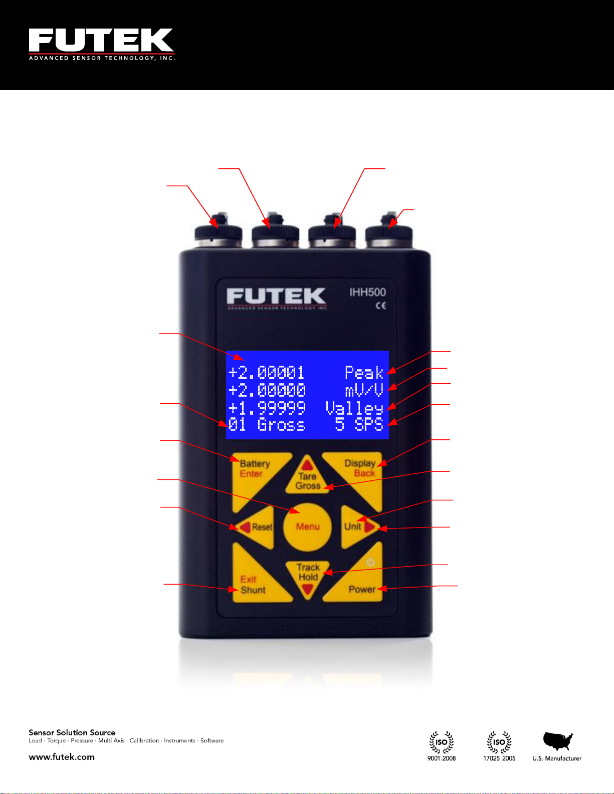
Power
USB Output
Sensor
Power Key
Navigation Keys
Larger Font
Display Options
16x4 Character LCD
Battery Indicator
Peak/Valley Reset
Shunt Calibration
Verification
Active Channel
Number
Peak Value
Tracking
Valley Value
Tare/ Gross
Track/ Hold
Menu
Sampling rate
Unit
5 Features
5.1 IHH500 Overview
EM1001-B
- 10 -
Page 11
10 Thomas, Irvine, CA 92618 USA
Tel: (949) 465-0900
Fax: (949) 465-0905
Toll Free: (800) 23 FUTEK
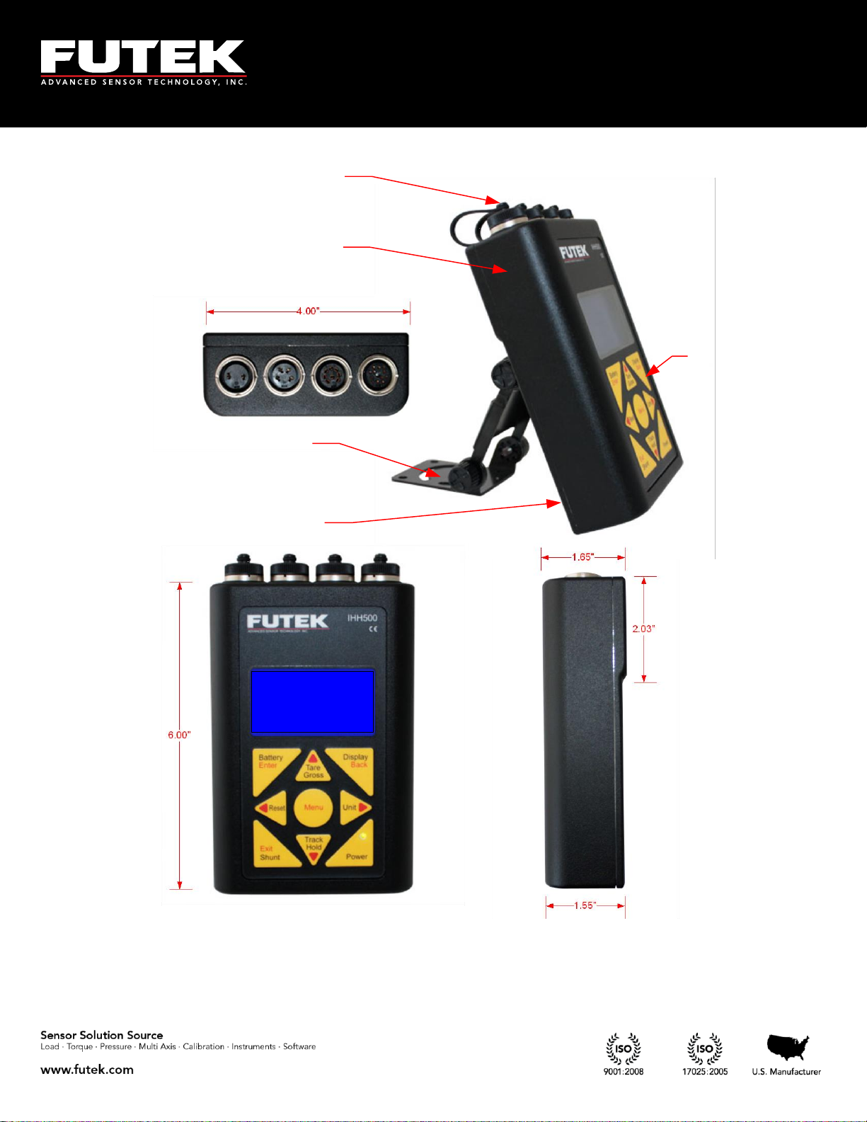
Tactile Membrane
Switches
Bumpons on back
Adjustable Mount
Submersible
Aluminum Enclosure
Dust Protection
Caps- IP67
FUTEK ADVANCED
SENSOR TECH INC.
IHH500 - ELITE
MADE IN USA
In the welcome message of the Pro version, “PRO” will be displayed.
Above it is shown that the IHH500 is submersible
EM1001-B
- 11 -
Page 12
10 Thomas, Irvine, CA 92618 USA
Tel: (949) 465-0900
Fax: (949) 465-0905
Toll Free: (800) 23 FUTEK
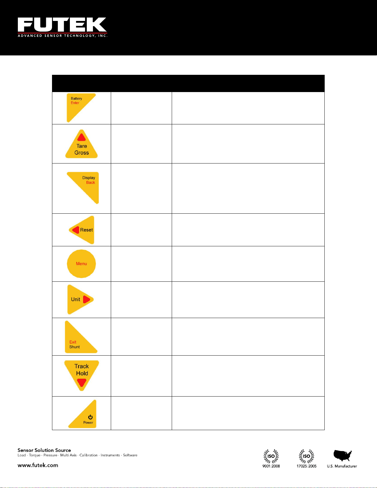
Front Panel
Button
Function of Button
in Menu Mode
Function of Button in Normal Mode
Enter
Displays battery life time
▲Arrow
Allows the user to toggle between displaying the tare
and gross values. This can be used to remove any
fixture weights.
Back
Allows the user to toggle between two different size
fonts. This key selects one of the four different states
in normal mode and one of the five different states
when a rotary sensor with an encoder is being
monitored. In this case rpm, torque, angle and
power will be displayed.
◄ Arrow
Allows the user to reset the peak/ valley or angle (in
rotary sensors with an encoder)
N/A
Start navigation
► Arrow
Allows the user to toggle between four groups of
engineering units (Force, Torque, Pressure, and
Displacement) and the standard mV/V.1
Exit
Allows the user to shunt the current reading. The
device shunts a resistor across the -Excitation and Signal connections.2
▼ Arrow
Allows the user to freeze the current reading. HOLD
will be displayed on the LCD showing that it has
been held. When the button or any other key is
pressed, the hold command will be cancelled.2
ON/OFF
ON/OFF
EM1001-B
- 12 -
Page 13

10 Thomas, Irvine, CA 92618 USA
Tel: (949) 465-0900
Fax: (949) 465-0905
Toll Free: (800) 23 FUTEK
1
Engineering units can only be converted within its own category.
Force (Mass): µg, mg, g, kg, M- tone, dyn, kdyn, Mdyn, N, kN, oz, lbs, klb, ton (US), ton (UK)
Torque: g-mm, g-cm, kg-cm, kg-m, N-mm, N-cm, N-m, KN-m, in-oz, in-lb, ft-lb
Pressure: Pa, kPa, mbar, bar, MPa, kg/cm², atm (standard atmosphere), mm-HG, in-H2O,
ft-H2O, psi, kpsi
Displacement: mm, cm, dm, m, km, in, ft, yds, mile
2
Pressing SHUNT will disable the HOLD function, but pressing HOLD will not disable the SHUNT
function.
Note: When a torque sensor is configured, the HOLD and SHUNT keys are disabled on the main page
showing the speed, angle and torque. Using the HOLD and SHUNT keys will prompt a warning
message.
EM1001-B
- 13 -
Page 14
10 Thomas, Irvine, CA 92618 USA
Tel: (949) 465-0900
Fax: (949) 465-0905
Toll Free: (800) 23 FUTEK
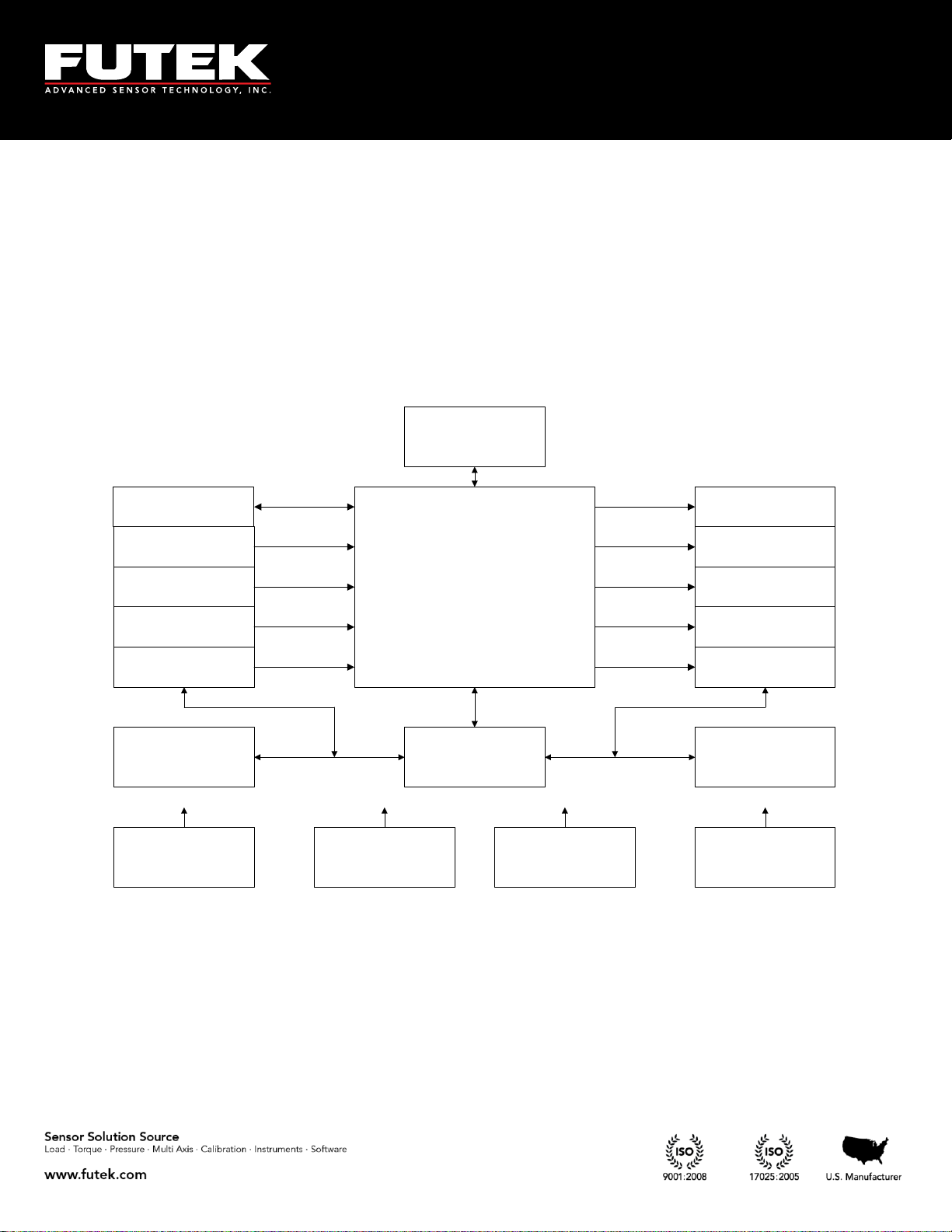
TEDS
Bridge Input
Pulse Input*
Voltage Input
Current Input
ASCII Output
Current Output
Voltage Output
Alarm Relay 1
Alarm Relay 2
USB
MCPU
Key Pad
Hardware
Controller
Display
(LCD)
Input Protection Output ProtectionPower SupplyBattery Charger
5.2 IHH500 Structure
* Available only in Elite Version.
EM1001-B
- 14 -
Page 15

10 Thomas, Irvine, CA 92618 USA
Tel: (949) 465-0900
Fax: (949) 465-0905
Toll Free: (800) 23 FUTEK
Welcome message will
be displayed at power on
Auto calibration will be applied when device is
turned on. The calibration will minimize any
effects of the temperature drift for either zero
(offset) or span. During the auto calibration process
the key pad is locked out and inaccessible. Brief
information about the active channel will be
displayed when calibration is complete.
CHANNEL 01
SERIAL 1
SENSOR BRIDGE
+2.00000 mV/V
TEMPLATE 33
SERIAL 123456
20.0000 LBS
1.98765 mV/V
AUTO CALIBRATION
IN PROGRESS
PLEASE WAIT 11
....
FUTEK ADVANCED
SENSOR TECH INC.
IPM650-PRO
MADE IN USA
5.3 Main Display
Depending on whether TEDS detect is enabled or not (see section 6.8.4), the following Sensor Profile will
be displayed for 10 seconds: TEDS enabled (left), TEDS disabled (right).
EM1001-B
- 15 -
Page 16

10 Thomas, Irvine, CA 92618 USA
Tel: (949) 465-0900
Fax: (949) 465-0905
Toll Free: (800) 23 FUTEK
+2.00001 Peak
+2.00000 mV/V
+1.99999 Valley
01 Gross 5 SPS
After 10 seconds the following message will be displayed.
EM1001-B
- 16 -
Page 17

10 Thomas, Irvine, CA 92618 USA
Tel: (949) 465-0900
Fax: (949) 465-0905
Toll Free: (800) 23 FUTEK
After displaying the Valley, the next change will
direct you to the main page again.
PK
+2.00001
01 GROSS mV/V
PK
+0.00001
01 TARE mV/V
TR
+2.00000
01 GROSS mV/V
TR
+0.00000
01 TARE mV/V
VY
+1.99999
01 GROSS mV/V
VY
-0.00001
01 TARE mV/V
+2.0000 Peak
+2.00000 mV/V
+1.99999 Valley
01 Gross 5SPS
Pressing the display key will change the reading to a larger font. Pressing it again will switch between
modes while still in the large font. The tare and gross modes can also be used while in the larger font
mode.
EM1001-B
- 17 -
Page 18

10 Thomas, Irvine, CA 92618 USA
Tel: (949) 465-0900
Fax: (949) 465-0905
Toll Free: (800) 23 FUTEK
+60000 RPM
+400 N-m
+1800 DEG
INVALID UNIT
+60000 RPM
+400 N-m
+1800 DEG
+2513.27 KW
For rotary torque sensors, the following screen will be displayed before returning to the main screen.
NOTE: To monitor Torque, Speed, Angle, and Power on the SENSIT Test and Measurement software
during live graphing, the screen of IHH500 should be changed by pressing the “DISPLAY” key. The
following screen will be displayed:
If an incorrect unit (other than torque) has been selected for a rotary torque sensor, an error message will
be displayed on the last row.
Note: When a torque sensor is configured, the HOLD and SHUNT keys are disabled on the main page
showing the speed, angle and torque. Using the HOLD and SHUNT keys will prompt a warning
message.
EM1001-B
- 18 -
Page 19

10 Thomas, Irvine, CA 92618 USA
Tel: (949) 465-0900
Fax: (949) 465-0905
Toll Free: (800) 23 FUTEK
+3.03461 Peak
+3.03460 mV/V
+1.59484 Valley
01 Gross SHUNT
The shunt key can be pressed any time after the device has been calibrated and a new sensor profile has
been loaded. The simulated value is to be used as a calibration reference. SHUNT will blink on the
display when enabled.
When both SHUNT and HOLD are active on the last row, the display will switch between blinking
SHUNT and blinking HOLD.
EM1001-B
- 19 -
Page 20

10 Thomas, Irvine, CA 92618 USA
Tel: (949) 465-0900
Fax: (949) 465-0905
Toll Free: (800) 23 FUTEK
The Battery key will allow you to view the battery
life time.
Pressing the battery button while the charger is
plugged in will display a battery charging screen.
Whenever the battery level drops below 6.5V, a
warning message will be displayed.
Whenever the battery level exceeds 8V and the
charger is connected, a warning message will be
displayed.
BATTERY FULL!
YOU CAN UNPLUG
BATTERY CHARGER
FROM THE DEVICE
BATTERY LOW!
CONNECT THE
BATTERY CHARGER
TO THE DEVICE
ĄĆĆĆĆĆĆĆĆĆĆĂ
ćĆĆĆĆĆĆĆĆĆĆĆĆ
ąĆĆĆĆĆĆĆĆĆĆă
CHARGING: 28%
ĄĆĆĆĆĆĆĆĆĆĆĂ
ćĆĆĆĆĆĆĆĆĆĆĆĆ
ąĆĆĆĆĆĆĆĆĆĆă
CHARGING: 100%
EM1001-B
- 20 -
Page 21

10 Thomas, Irvine, CA 92618 USA
Tel: (949) 465-0900
Fax: (949) 465-0905
Toll Free: (800) 23 FUTEK
Leading, TTL
Lagging, TTL
60000
2 RPMT
NTP
There are two pulse signals, P1 and P2, which are used to indicate speed, angle, power, and the direction
of rotation. These pulses are 90 degrees out of phase, and depending on which pulse is leading or
lagging or how many pulses are present in a certain time frame, the IHH500 can calculate these values.
Calculation of Power:
Power is calculated by using the following formula:
Where:
P: mechanical power in kW
T: torque in N-m
RPM: speed in rev / min
Calculating the Power Units:
If the g-mm, g-cm, g-m or N-mm units have been defined, the mechanical power is automatically
calculated in W
If the kg-cm, kg-m, or N-m units have been defined, the mechanical power is automatically
calculated in kW
If the kN-m unit has been defined, the mechanical power is automatically calculated in MW
If the In-Ib, oz-in or ft-Ib units have been defined, the mechanical power is automatically
calculated in HP
Direction of Rotation:
Since there are two pulses, a direction of rotation (CW or CCW) can be defined depending on which
pulse is leading.
EM1001-B
- 21 -
Page 22

10 Thomas, Irvine, CA 92618 USA
Tel: (949) 465-0900
Fax: (949) 465-0905
Toll Free: (800) 23 FUTEK
PPR
fN60
PPR
RPM
60
Calculation of Speed:
The input frequency that can be evaluated for recording the speed is used in defining the speed. The
input speed based on the pulses per rotation can be calculated as follows:
Where:
N: Speed (RPM)
f: Frequency
PPR: User-defined pulses per rotation (selectable up to 9999)
Angle calculation:
After calculating the Angle will be computed based on pulse per rotation.
Where:
RPM: Revolution per Minute
PPR: Pulse per Rotation
α: Angle
Note: the resolution of Angle calculation is 1 degree.
EM1001-B
- 22 -
Page 23
10 Thomas, Irvine, CA 92618 USA
Tel: (949) 465-0900
Fax: (949) 465-0905
Toll Free: (800) 23 FUTEK
POWER OUTPUT
CALIBRATION
ZERO LOAD (+)
SENSITIVITY (+)
SENSOR CONFIG
ZERO LOAD (-)
FULLSCALE (+)
FULLSCALE (-)
ACTION
SENSOR PROFILE
LCD SETTING
OUTPUT CONFIG
TEDS DATA
SYSTEM SETTING
SAMPLING RATE
VOLTAGE CONFIG
MOVING AVERAGE
CURRENT CONFIG
DIGITAL ASCII
BRIGHTNESS
CONTRAST
VOLTAGE OUTPUT
TEDS PAGES
TEDS DEVICE
UNIT SELECTION
USB OUTPUT
ASCII OUTPUT
CURRENT OUTPUT
RELAY2 OUTPUT
CHANNEL SELECT
RELAY1 OUTPUT
SENSOR CAPACITY
DIGITS SELECT
SERIAL NUMBER
LOGGING RATE
DURATION(SEC)
PULSE PER ROTATION
DIRECTION
FIRST PEAK (THD)
ALARM LIMIT
FIRST VALLEY (THD)
AUTO RESET TIMER
HIGH
ALARM LIMIT
LOW
LIMIT & THD
SENSITIVITY (-)
PEAK / VALLEY
PULSE INPUT
VOLTAGE INPUT
SAVE CHANGES
CURRENT INPUT
BRIDGE INPUT
AUTO RESET
MIN/MAX DIFF
AUTO DETECTION
LOCK SETTING
CURRENT VALUE
ALARM RELAY2
ALARM RELAY1
ALARM ACTIVITY
(INTERNAL, EXTERNAL)
VIEW CHANNEL
AUTO LCD OFF
DIAGNOSTIC
mV/V
EDIT CHANNEL
DELETE CHANNEL
NEW CHANNEL
FORCE (MASS )
TORQUE
PRESS URE
LOCKOUT PROFILE
DISPLACEMENT
UNLOCK PROFILE
CHANGE PASSWORD
(SEC)
LOAD DATA
INTERFACES
ALARM CONFIG
EXISTING CH(S)
DATA LOGGING
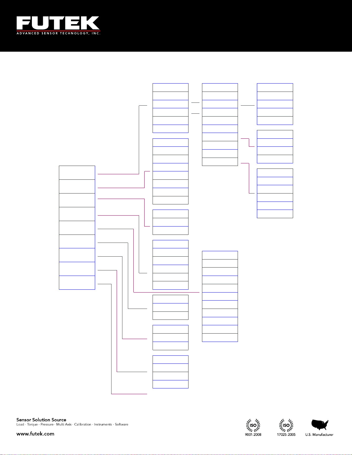
6 Main Menu Overview
EM1001-B
- 23 -
Page 24
10 Thomas, Irvine, CA 92618 USA
Tel: (949) 465-0900
Fax: (949) 465-0905
Toll Free: (800) 23 FUTEK
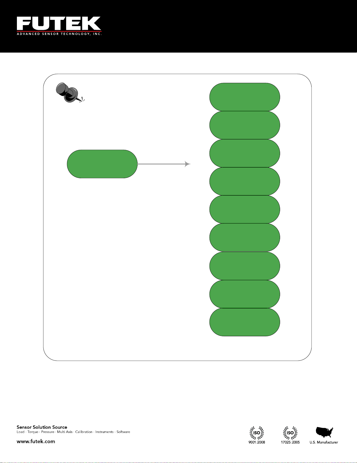
Main Menu
Sensor Profile
System setting
Data Logging
Output Config
interfaces
LCD Setting
Diagnostic
TEDS Data
Lock Setting
EM1001-B
- 24 -
Page 25

10 Thomas, Irvine, CA 92618 USA
Tel: (949) 465-0900
Fax: (949) 465-0905
Toll Free: (800) 23 FUTEK
LOCK SETTINGS
TEDS DATA
► DIAGNOSTIC
------------
INTERFACES
LCD SETTING
► LOCK SETTING
TEDS DATA
SENSOR PROFILE
SYSTEM SETTING
►DATA LOGGING
OUTPUT CONFIG
Press the MENU key to enter the main menu.
Use ▲▼keys to select the desired menu option.
Press ENTER to navigate to the submenu.
The EXIT button can be used at any time to exit any menu or sub menu and return to the display page.
The BACK button can be used at any time to step back from any sub menu.
EM1001-B
- 25 -
Page 26
10 Thomas, Irvine, CA 92618 USA
Tel: (949) 465-0900
Fax: (949) 465-0905
Toll Free: (800) 23 FUTEK
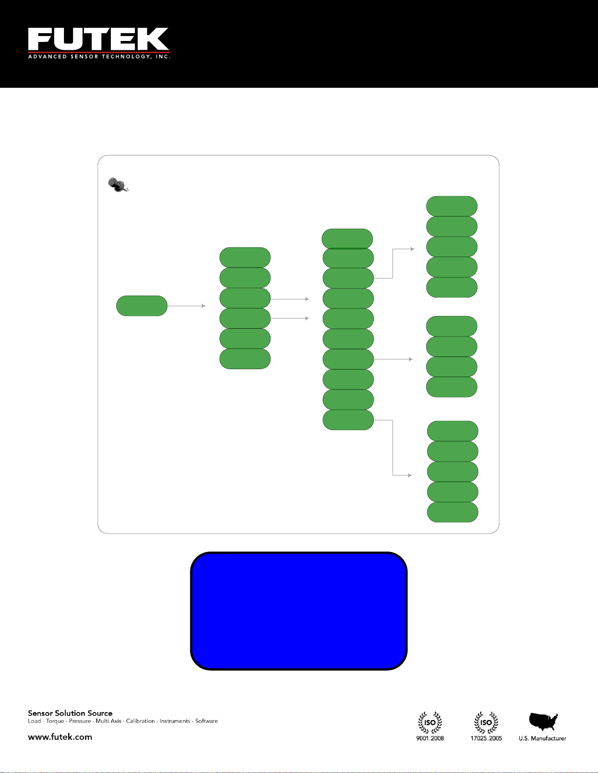
Sensor profile
ExistingChannel
View Channel
New Channel
Edit Channel
Save Changes
Delete Channel
Direction
Unit Selection
Sensor capacity
Sensitivity (+)
Sensitivity (-)
Calibration
Force
Torque
Pressure
Displacement
mV/V
Pulse per
Rotation
First PK (THD)
First VY (THD)
MIN/MAX Diff
Alarm Limit High
Auto Reset Timer
Serial Number
Limit & THD
Zero Load (+)
Full Scale (+)
Zero Load (-)
Full Scale (-)
Sensor
Configuration
► SENSOR PROFILE
SYSTEM SETTING
DATA LOGGING
OUTPUT CONFIG
6.1 Sensor Profile
EM1001-B
- 26 -
Page 27

10 Thomas, Irvine, CA 92618 USA
Tel: (949) 465-0900
Fax: (949) 465-0905
Toll Free: (800) 23 FUTEK
01¾ NA NA NA
NA NA NA NA
NA NA NA NA
NA NA NA TD
01¾ NA NA NA
NA NA NA NA
NA NA NA NA
NA NA NA
► EXISTING CH(S)
VIEW CHANNEL
NEW CHANNEL
EDIT CHANNEL
► EDIT CHANNEL
SAVE CHANGES
DELETE CHANNEL
-----------
► EXISTING CH(S)
VIEW CHANNEL
NEW CHANNEL
EDIT CHANNEL
Select “SENSOR PROFILE” from the main menu options and press ENTER. The following options are
available: EXISTING CH(S), VIEW CHANNEL, NEW CHANNEL, EDIT CHANNEL, SAVE
CHANGESand DELETE CHANNEL.
6.1.1 Existing Channels
Scroll to “EXISTING CH(S)” using the ▲▼ keys and press ENTER to view the different sensor profiles.
The IHH500 is able to store up to 15 different sensor profiles.
The active channel number will be shown with a check mark on the right.
This function is useful to have a quick view of the number of channels (sensor profile) that have been
stored in the internal memory and whether they are active or not. The active channel has a check mark
next to it. For example, in this specific figure only channel 01 exists and is active.
TEDS activity is shown separately. If TEDS is present it will be shown in the bottom right area.
BACK can be pressed at any time to return to other sensor profile options.
EM1001-B
- 27 -
Page 28

10 Thomas, Irvine, CA 92618 USA
Tel: (949) 465-0900
Fax: (949) 465-0905
Toll Free: (800) 23 FUTEK
CHANNEL 01
SERIAL 0
SENSOR BRIDGE
+2.00000 mV/V
EXISTING CH(S)
► VIEW CHANNEL
NEW CHANNEL
EDIT CHANNEL
6.1.2 View Channel
Scroll to select “VIEW CHANNEL” form the “SENSOR PROFILE” using the▲▼ keys and press ENTER
to view: channel number, sensor type, serial number, capacity and engineering unit. If currently more
than one channel exists, pressing the arrow ◄►keys on the keypad will cycle through the existing
channels.
EM1001-B
- 28 -
Page 29

10 Thomas, Irvine, CA 92618 USA
Tel: (949) 465-0900
Fax: (949) 465-0905
Toll Free: (800) 23 FUTEK
WARNING!
EXIT WITHOUT
SAVING PROFILE?
<YES> <NO>
EXISTING CH(S)
VIEW CHANNEL
► NEW CHANNEL
EDIT CHANNEL
SELECT DESIRED
CHANNEL NUMBER
USING ◄,► KEYS
[02]
► SENSOR CONFIG
DIRECTION
UNIT SELECTION
SENSOR CAPACITY
6.1.3 New Channel
Scroll to “NEW CHANNEL” from the “SENSOR PROFILE” using the▲▼ keys and press ENTER. Use
the ◄► to select the remaining 2 to 15 channels. Press ENTER to set the data for desired channel.
Note: The first channel is already set as default and will be displayed on the screen if no other channel
has been set.
In order to set the new channel data the following steps must be taken exactly in the order in which it is
shown on the screen, the ▼key cannot be used to skip the steps. If EXIT is pressed while setting the new
channel or editing an existing channel, following warning message will be displayed:
EM1001-B
- 29 -
Page 30

10 Thomas, Irvine, CA 92618 USA
Tel: (949) 465-0900
Fax: (949) 465-0905
Toll Free: (800) 23 FUTEK
SELECTED FEATURE
IS NOT AVAILABLE
AT THIS TIME
(HIT ENTER/BACK)
This function is not available if lockout option is enabled. See section 6.7 for further information how to
enable or disable lock settings. If this device is being used for the first time, it has not been locked yet.
If this device is already locked, the following message will appear if “NEW CHANNEL” is selected:
EM1001-B
- 30 -
Page 31

10 Thomas, Irvine, CA 92618 USA
Tel: (949) 465-0900
Fax: (949) 465-0905
Toll Free: (800) 23 FUTEK
OPERATION
WAS EXECUTED
SUCCESSFULLY
(HIT ENTER/BACK)
AUTO CALIBRATION
IN PROGRESS
PLEASE WAIT 12
…
LOADING PROFILE
IN PROGRESS
PLEASE WAIT 30
SELECT DESIRED
SENSOR TYPE
USING ◄,► KEYS
[FULL BRIDGE]
► SENSOR CONFIG
DIRECTION
UNIT SELECTION
SENSOR CAPACITY
6.1.3.1 Sensor Configuration
Scroll to “SENSOR CONFIG” from “NEW CHANNEL” using ▲▼ keys and press the ENTER to set a
new channel. “SENSOR CONFIG” can also be selected from “EDIT CHANNEL” to make modifications
on the existing channels except channel 1. Use the ◄►keys to select the sensor type as either “FULL
BRIDGE”,”VOLTAGE OUTPUT”, “CURRENT OUTPUT”, “ BRIDGE& PULSE”, “VOLTAGE &
PULSE” or “CURRENT & PULSE”.
Note: Pulse selection is only available in Elite Version.
Any time a new sensor type is selected, which was not defined before, the device will automatically
calibrate itself after it loads the new profile. The following messages will be seen on the screen.
The following message may be seen if the sensor type is the same as current profile.
EM1001-B
- 31 -
Page 32

10 Thomas, Irvine, CA 92618 USA
Tel: (949) 465-0900
Fax: (949) 465-0905
Toll Free: (800) 23 FUTEK
OPERATION
WAS EXECUTED
SUCCESSFULLY
(HIT ENTER/BACK)
► DIRECTION
UNIT SELECTION
SENSOR CAPACITY
SENSITIVITY(+)
SELECT DESIRED
DIRECTION TYPE
USING ◄,► KEYS
[UNI-DIRECTION]
6.1.3.2 Direction
Scroll to “DIRECTION” from “NEW CHANNEL” using the▲▼ keys and press ENTER. “DIRECTION”
can also be selected from “EDIT CHANNEL” to make modifications on the existing channels except
channel one.
Using the ◄►keys on the keypad select either uni-direction or bi-direction.
EM1001-B
- 32 -
Page 33

10 Thomas, Irvine, CA 92618 USA
Tel: (949) 465-0900
Fax: (949) 465-0905
Toll Free: (800) 23 FUTEK
► PRESSURE
DISPLACEMENT
mV/V
------------
FORCE (MASS)
► TORQUE
PRESSURE
DISPLACEMENT
DIRECTION
► UNIT SELECTION
SENSOR CAPACITY
SENSITIVITY(+)
6.1.3.3 Unit selection
Scroll to “UNIT SELECTION” from “NEW CHANNEL” using the ▲▼ keys and press ENTER. It can
also be selected from “EDIT CHANNEL” to make modifications on the existing channel except channel
one. Using the ▲▼keys select one of the following four groups of Engineering Units: FORCE, TORQUE,
PRESSURE, and DISPLACEMENT and standard mV/V for the new channel.
EM1001-B
- 33 -
Page 34

10 Thomas, Irvine, CA 92618 USA
Tel: (949) 465-0900
Fax: (949) 465-0905
Toll Free: (800) 23 FUTEK
OPERATION
WAS EXECUTED
SUCCESSFULLY
(HIT ENTER/BACK)
SELECT DESIRED
ENGINEERING UNIT
USING ◄,► KEYS
[êg]
► FORCE (MASS)
TORQUE
PRESSURE
DISPLACEMENT
6.1.3.3.1 Force (MASS)
Scroll to “FORCE (MASS)” from “UNIT SELECTION” using the▲▼ keys and press ENTER. The
following options can be selected for force: µg, mg, g, kg, M- tone, dyn, kdyn, Mdyn, N, kN, oz, lbs, klb,
ton (US) and ton (UK). Once the desired force unit is selected, the following message will appear.
EM1001-B
- 34 -
Page 35

10 Thomas, Irvine, CA 92618 USA
Tel: (949) 465-0900
Fax: (949) 465-0905
Toll Free: (800) 23 FUTEK
OPERATION
WAS EXECUTED
SUCCESSFULLY
(HIT ENTER/BACK)
SELECT DESIRED
ENGINEERING UNIT
USING ◄,► KEYS
[g-mm]
FORCE (MASS)
► TORQUE
PRESSURE
DISPLACEMENT
6.1.3.3.2 Torque
Scroll to “TORQUE” from “UNIT SELECTION” using the▲▼ keys and press ENTER. The following
options for torque can be selected: g-mm, g-cm, g-m, kg-cm, kg-m, N-mm, N-cm, N-m, kN-m, in-oz, in-
lb, and ft-lb. Once the desired torque unit is selected, the following message will be shown.
Note: When a torque sensor is configured, the HOLD and SHUNT keys are disabled on the main page
showing the speed, angle and torque. Using the HOLD and SHUNT keys will prompt a warning
message.
EM1001-B
- 35 -
Page 36

10 Thomas, Irvine, CA 92618 USA
Tel: (949) 465-0900
Fax: (949) 465-0905
Toll Free: (800) 23 FUTEK
OPERATION
WAS EXECUTED
SUCCESSFULLY
(HIT ENTER/BACK)
SELECT DESIRED
ENGINEERING UNIT
USING ◄,► KEYS
[Pa]
FORCE (MASS)
TORQUE
► PRESSURE
DISPLACEMENT
6.1.3.3.3 Pressure
Scroll to “PRESSURE” from “UNIT SELECTION” using the▲▼ keys and press ENTER. The following
options can be selected for pressure: Pa, kPa, mbar, bar, MPa, kg/cm², atm (standard atmosphere), mm-
HG, in-H2O, ft-H2O, psi, and kpsi. Once the desired pressure unit is selected, the following message
will be shown.
EM1001-B
- 36 -
Page 37

10 Thomas, Irvine, CA 92618 USA
Tel: (949) 465-0900
Fax: (949) 465-0905
Toll Free: (800) 23 FUTEK
OPERATION
WAS EXECUTED
SUCCESSFULLY
(HIT ENTER/BACK)
SELECT DESIRED
ENGINEERING UNIT
USING ◄,► KEYS
[mm]
PRESSURE
► DISPLACEMENT
mV/V
------------
6.1.3.3.4 Displacement
Scroll to “DISPLACEMENT” from “UNIT SELECTION” using the▲▼ keys and press ENTER. The
following units can be selected for displacement: mm, cm, dm, m, km, in, ft, yds, and mile. Once the
desired displacement unit is selected, the following message will be shown.
EM1001-B
- 37 -
Page 38

10 Thomas, Irvine, CA 92618 USA
Tel: (949) 465-0900
Fax: (949) 465-0905
Toll Free: (800) 23 FUTEK
OPERATION
WAS EXECUTED
SUCCESSFULLY
(HIT ENTER/BACK)
PRESSURE
DISPLACEMENT
► mV/V
-------------
6.1.3.3.5 mV/V
Scroll to “mV/V” from “UNIT SELECTION” using the ▲▼ keys and press ENTER. Once the desired
displacement unit is selected, the following message will be shown.
EM1001-B
- 38 -
Page 39

10 Thomas, Irvine, CA 92618 USA
Tel: (949) 465-0900
Fax: (949) 465-0905
Toll Free: (800) 23 FUTEK
OPERATION
WAS EXECUTED
SUCCESSFULLY
(HIT ENTER/BACK)
SELECT DESIRED
VALUE
USING ARROW KEYS
[2.00000]
SENSOR CONFIG
DIRECTION
UNIT SELECTION
► SENSOR CAPACITY
6.1.3.4 Sensor Capacity
Scroll to “SENSOR CAPACITY” from “NEW CHANNEL” using the▲▼ keys and press ENTER.
“SENSOR CAPACITY” can also be selected from “EDIT CHANNEL” to make modifications on the
existing channels except channel one.
Using the◄► keys move the cursor to the desired placement and use the ▲▼keys to select the desired
number or decimal position. The capacity can be selected from 0.00001 to 9999999.
EM1001-B
- 39 -
Page 40

10 Thomas, Irvine, CA 92618 USA
Tel: (949) 465-0900
Fax: (949) 465-0905
Toll Free: (800) 23 FUTEK
OPERATION
WAS EXECUTED
SUCCESSFULLY
(HIT ENTER/BACK)
AUTO CALIBRATION
IN PROGRESS
PLEASE WAIT 15
………
LOADING PROFILE
IN PROGRESS
PLEASE WAIT 30
SELECT SENSOR
mV/V OUTPUT
USING ARROW KEYS
[2.00000]
SENSOR CONFIG
► SENSITIVITY(+)
UNIT SELECTION
SENSOR CAPACITY
6.1.3.5 Sensitivity (+)
Scroll to “SENSITIVITY (+)” from “NEW CHANNEL” using the▲▼ keys and press ENTER to set the
sensitivity for a new channel. “SENSITIVITY” can also be selected from “EDIT CHANNEL” to make
modifications on the existing channel except channel one. Sensitivity of the channel can be selected in
mV/V using the ◄►and the ▲▼keys.
If the actual sensitivity is not known, but the specific range is known, use the larger number. For example
if the sensitivity of the sensor is between 2 mV/V and 3 mV/V, 3mV/V should be entered. A live
calibration would then be needed to find the actual mV/V. Any time a new sensor sensitivity is set, the
device may do an auto calibration after it loads the new profile.
The following messages will be seen on the screen.
Note: Sensitivity can be defined for bridge sensors and voltage sensors. This option is disabled for
current sensors.
The following message will be seen if the sensor sensitivity is the same as current profile.
EM1001-B
- 40 -
Page 41

10 Thomas, Irvine, CA 92618 USA
Tel: (949) 465-0900
Fax: (949) 465-0905
Toll Free: (800) 23 FUTEK
AUTO CALIBRATION
IN PROGRESS
PLEASE WAIT 15
………
LOADING PROFILE
IN PROGRESS
PLEASE WAIT 30
SELECT SENSOR
mV/V OUTPUT
USING ARROW KEYS
[2.00000]
SENSOR CONFIG
► SENSITIVITY(-)
UNIT SELECTION
SENSOR CAPACITY
Note: For voltage sensor device asks for voltage output.
6.1.3.6 Sensitivity (-)
Scroll to “SENSITIVITY (-)” from “NEW CHANNEL” using the ▲▼ keys and press ENTER to set the
sensitivity for a new channel. “SENSITIVITY” can also be selected from “EDIT CHANNEL” if to make
modifications on the existing channels except channel one. Sensitivity of the channel can be selected in
mV/V using the◄► and the ▲▼keys.
If the actual sensitivity is not known, but the specific range is known, use the larger number. For example
if the sensitivity of the sensor is between 2 mV/V and 3 mV/V, 3mV/V should be entered. A live
calibration would then be needed to find the actual mV/V. Any time that a new sensor sensitivity is set,
the device may do an auto calibration after it loads the new profile.
Note that sensitivity can be defined for bridge sensors and voltage sensors. This option is disabled for
current and pulse sensors.
Note: If a Uni-directional sensor is configured in “DIRECTION” the section is not available, otherwise
if the sensor is Bi-directional configured and the following step shall be taken for the negative values:
EM1001-B
- 41 -
Page 42

10 Thomas, Irvine, CA 92618 USA
Tel: (949) 465-0900
Fax: (949) 465-0905
Toll Free: (800) 23 FUTEK
OPERATION
WAS EXECUTED
SUCCESSFULLY
(HIT ENTER/BACK)
The following message will be seen if the sensor sensitivity is the same as current profile.
EM1001-B
- 42 -
Page 43

10 Thomas, Irvine, CA 92618 USA
Tel: (949) 465-0900
Fax: (949) 465-0905
Toll Free: (800) 23 FUTEK
OPERATION
WAS EXECUTED
SUCCESSFULLY
(HIT ENTER/BACK)
APPLY
ZERO LOAD(+)
CALIBRATION
THEN PRESS ENTER
ZERO LOAD (+)
► FULLSCALE (+)
ZERO LOAD (-)
FULLSCALE (-)
SENSITIVITY(-)
► CALIBRATION
PULSE/ROTATE
SERIAL NUMBER
6.1.3.7 Calibration
Scroll to “CALIBRATION” from “NEW CHANNEL” using ▲▼ keys and press ENTER to set it for the
new channel. “CALIBRATION” can also be selected from “EDIT CHANNEL” to make modifications on
the existing channels except channel one.
Note: This function is dedicated for precise calibration (live calibration), however if the user would not
like to apply the load, in the sensitivity selection (6.1.3.5 & 6.1.3.6) manipulating method must be done
accurately otherwise the calculation is not correct.
For example: Using a calibration certification with the sensitivity, the number must be entered in the
sensitivity selection (6.1.3.5& 6.1.3.6) and this step can be skipped. However it is recommended to use this
step and manually live calibrate the sensor.
If user does not have actual sensitivity and has already entered an estimated value in Sensitivity Section
(6.1.3.5 & 6.1.3.6) this step must be executed carefully.
After performing all calibration steps and entering zero load and full scale, device is able to calculate
the actual SENSITIVITY value and update it. SENSOR CONFIGURATION menu will now contain
the actual value.
6.1.3.7.1 Zero Load (+)
Scroll to “ZERO LOAD (+)” from “CALIBRATION” using the ▲▼ keys and press ENTER.
EM1001-B
- 43 -
Page 44

10 Thomas, Irvine, CA 92618 USA
Tel: (949) 465-0900
Fax: (949) 465-0905
Toll Free: (800) 23 FUTEK
OPERATION
WAS EXECUTED
SUCCESSFULLY
(HIT ENTER/BACK)
APPLY
FULL SCALE(-)
CALIBRATION
THEN PRESS ENTER
OPERATION
WAS EXECUTED
SUCCESSFULLY
(HIT ENTER/BACK)
APPLY
ZERO LOAD(-)
CALIBRATION
THEN PRESS ENTER
OPERATION
WAS EXECUTED
SUCCESSFULLY
(HIT ENTER/BACK)
APPLY
FULL SCALE(+)
CALIBRATION
THEN PRESS ENTER
6.1.3.7.2 Full Scale (+)
Scroll to “FULL SCALE (+)” from “CALIBRATION” using the ▲▼ keys and press ENTER.
If the channel “DIRECTION” is defined as “BI-DIRECTION” it will be prompt to apply the full scale
calibration (-) as well as zero load (-) for the reverse direction.
6.1.3.7.3 Zero Load (-)
Scroll to “ZERO LOAD (-)” from “CALIBRATION” using the▲▼ keys and press ENTER.
6.1.3.7.4 Full Scale (-)
Scroll to “FULL SCALE (-)” from “CALIBRATION” using the▲▼ keys and press ENTER.
EM1001-B
- 44 -
Page 45

10 Thomas, Irvine, CA 92618 USA
Tel: (949) 465-0900
Fax: (949) 465-0905
Toll Free: (800) 23 FUTEK
OPERATION
WAS EXECUTED
SUCCESSFULLY
(HIT ENTER/BACK)
SELECT DESIRED
VALUE
USING ARROW KEYS
[0360]
DIRECTION
CALIBRATION
►PULSE/ROTATE
SERIAL NUMBER
6.1.3.8 Pulse per rotation
Scroll to “PULSE/ROTATE” from “NEW CHANNEL” using the▲▼ keys and press ENTER.
“PULSE/ROTATE” can also be selected from “EDIT CHANNEL” to make modifications on the existing
channels except channel one.
Note: This option is only available for rotary sensors with encoders as defined in sensor configuration
sub-menu (6.1.3.1).
Using the◄► keys move the cursor to the desired placemen, and use the ▲▼ keys the desired number.
Number of pulse per rotations (PPR) can be defined for either rotary or speed sensors. Up to 9999 pulse
per rotation can be defined.
A confirmation message will be displayed confirming that desired operation was successfully executed.
EM1001-B
- 45 -
Page 46

10 Thomas, Irvine, CA 92618 USA
Tel: (949) 465-0900
Fax: (949) 465-0905
Toll Free: (800) 23 FUTEK
OPERATION
WAS EXECUTED
SUCCESSFULLY
(HIT ENTER/BACK)
SELECT DESIRED
VALUE
USING ARROW KEYS
[0000000]
CALIBRATION
PULSE/ROTATE
► SERIAL NUMBER
LIMIT & THD
6.1.3.9 Serial number
Scroll to “SERIAL NUMBER” from “NEW CHANNEL” using the ▲▼ keys and press ENTER. “SERIAL
NUMBER” can also be selected from “EDIT CHANNEL” to make modifications on the existing channels
except channel one.
Using the◄► keys, the cursor can be moved among the seven digits and use the ▲▼ keys to select the
desired serial number.
A confirmation message will be displayed confirming operation was successfully executed.
EM1001-B
- 46 -
Page 47

10 Thomas, Irvine, CA 92618 USA
Tel: (949) 465-0900
Fax: (949) 465-0905
Toll Free: (800) 23 FUTEK
CALIBRATION
PULSE/ROTATE
SERIAL NUMBER
► LIMIT & THD
6.1.3.10 Limit & THD
Scroll to LIMIT & THD” from “NEW CHANNEL” using the▲▼ keys and press ENTER.” LIMIT &
THD” can also be selected from “EDIT CHANNEL” to make modifications on the existing channels
except channel one.
EM1001-B
- 47 -
Page 48

10 Thomas, Irvine, CA 92618 USA
Tel: (949) 465-0900
Fax: (949) 465-0905
Toll Free: (800) 23 FUTEK
OPERATION
WAS EXECUTED
SUCCESSFULLY
(HIT ENTER/BACK)
SELECT DESIRED
VALUE
USING ARROW KEYS
[+050.00%]
► FIRST PK (THD)
FIRST VY (THD)
MIN / MAX DIFF
ALARM LIMIT HI
6.1.3.10.1 First Peak THD
Scroll to “FIRST PK THD” from “LIMIT & THD” using the▲▼ keys and press ENTER.
Use the arrow keys to move the cursor among the digits and select the desired number for the First Peak.
The sign value can also be changed from positive to negative in case a bi-directional sensor is configured.
A confirmation message will be displayed confirming operation was successfully executed.
(See Figures no.1 and 2 on page 50 for examples of threshold levels on one directional and two directional
sensors).
EM1001-B
- 48 -
Page 49

10 Thomas, Irvine, CA 92618 USA
Tel: (949) 465-0900
Fax: (949) 465-0905
Toll Free: (800) 23 FUTEK
FIRST PK (THD)
► FIRST VY (THD)
MIN / MAX DIFF
ALARM LIMIT HI
SELECT DESIRED
VALUE
USING ARROW KEYS
[+030.00%]
OPERATION
WAS EXECUTED
SUCCESSFULLY
(HIT ENTER/BACK)
6.1.3.10.2 First Valley THD
Scroll to “FIRST VY (THD)” from “LIMIT & THD” using the ▲▼ keys and press ENTER.
Use the arrow keys to move the cursor among the digits and select the desired number for the First
Valley. The sign value can also be changed from positive to negative in case a bi-directional sensor is
configured.
A confirmation message will be displayed confirming operation was successfully executed.
(See Figures no.1 and 2 on page 50 for examples of threshold levels on one directional and two directional
sensors).
EM1001-B
- 49 -
Page 50

10 Thomas, Irvine, CA 92618 USA
Tel: (949) 465-0900
Fax: (949) 465-0905
Toll Free: (800) 23 FUTEK
Unit
t
FV
FP
THD
FP THD
FV THD
Figure No.1
Example of One Directional Sensor
10%
80%
Unit
t
FV
FP
THD
FV THD
FP THD
Figure No.2
Example of Two Directional Sensor
-50%
50%
EM1001-B
- 50 -
Page 51

10 Thomas, Irvine, CA 92618 USA
Tel: (949) 465-0900
Fax: (949) 465-0905
Toll Free: (800) 23 FUTEK
OPERATION
WAS EXECUTED
SUCCESSFULLY
(HIT ENTER/BACK)
SELECT DESIRED
VALUE
USING ARROW KEYS
[+010.00%]
FIRST PK (THD)
FIRST VY (THD)
► MIN / MAX DIFF
ALARM LIMIT HI
6.1.3.10.3 MIN/MAX Differentiation
Scroll to “MIN / MAX DIFF” from “LIMIT & THD” using the▲▼ keys and press ENTER.
Use the arrow keys to move the cursor among the digits and select the desired number for the Min/Max
Differentiations. The sign value can also be changed from positive to negative in case a bi-directional
sensor is configured.
A confirmation message will be displayed confirming operation was successfully executed.
(See Figure no.3 on page 52 for examples of Min/Max Differentiation).
EM1001-B
- 51 -
Page 52

10 Thomas, Irvine, CA 92618 USA
Tel: (949) 465-0900
Fax: (949) 465-0905
Toll Free: (800) 23 FUTEK
A
B
Max/Min Diff
Figure No.3
Max/ Min Differentiation
X %
Caution should be taken in defining X, for the Max/Min Diff.
For example:
Consider the following data at points A and B:
A: 100 IL
B: 90IL
If X is considered less than 10%, A would not be considered as first peak, or B would not be considered as
first valley.
EM1001-B
- 52 -
Page 53

10 Thomas, Irvine, CA 92618 USA
Tel: (949) 465-0900
Fax: (949) 465-0905
Toll Free: (800) 23 FUTEK
OPERATION
WAS EXECUTED
SUCCESSFULLY
(HIT ENTER/BACK)
SELECT DESIRED
VALUE
USING ARROW KEYS
[+120.00%]
FIRST VY THD
MIN / MAX DIFF
► ALARM LIMIT HI
ALARM LIMIT LO
6.1.3.10.4 Alarm Limit High
Scroll to “ALARM LIMIT HI” from “LIMIT(S) & THD(S)” using the▲▼ keys and press ENTER.
Use the arrow keys to move the cursor among the digits and select the desired number for the Alarm
Limit High. The sign value can also be changed from positive to negative in case a bi-directional sensor is
configured.
A confirmation message will be displayed confirming operation was successfully executed.
(See Figures no. 4 and 5 on page 55 for examples of alarm threshold levels for one directional and two
directional sensors).
EM1001-B
- 53 -
Page 54

10 Thomas, Irvine, CA 92618 USA
Tel: (949) 465-0900
Fax: (949) 465-0905
Toll Free: (800) 23 FUTEK
MIN/MAX DIFF
A ALARM LIMIT HI
► ALARM LIMIT LO
AUTO RST (SEC)
SELECT DESIRED
VALUE
USING ARROW KEYS
[+010.00%]
OPERATION
WAS EXECUTED
SUCCESSFULLY
(HIT ENTER/BACK)
6.1.3.10.5 Alarm Limit Low
Scroll to “ALARM LIMIT LO” from “LIMIT & THD” using the ▲▼ keys and press ENTER.
Use the arrow keys to move the cursor among the digits and select the desired number for the Alarm
Limit Low. The sign value can also be changed from positive to negative in case a bi-directional sensor is
configured.
A confirmation message will be displayed confirming operation was successfully executed.
(See Figure no.4 and 5 on page 55 for examples of alarm threshold levels for one directional and two
directional sensors).
EM1001-B
- 54 -
Page 55

10 Thomas, Irvine, CA 92618 USA
Tel: (949) 465-0900
Fax: (949) 465-0905
Toll Free: (800) 23 FUTEK
Alarm Area
Alarm Area
10%
80%
Unit
t
Non Alarm Area
Figure No.4
Example of One Directional Sensor
Alarm Area
Alarm Area
-50%
50%
Unit
t
Non Alarm Area
Figure No.5
Example of Two Directional Sensor
EM1001-B
- 55 -
Page 56

10 Thomas, Irvine, CA 92618 USA
Tel: (949) 465-0900
Fax: (949) 465-0905
Toll Free: (800) 23 FUTEK
ALARM LIMIT HI
ALARM LIMIT LO
► AUTO RST (SEC)
---------
SELECT DESIRED
VALUE
USING ARROW KEYS
[0010]
OPERATION
WAS EXECUTED
SUCCESSFULLY
(HIT ENTER/BACK)
6.1.3.10.6 Auto Reset Timer
Scroll to “AUTO RST (SEC)” from “LIMIT & THD” using the▲▼ keys and press ENTER.
Use the arrow keys to move the cursor among the digits and select the desired number.
A confirmation message will be displayed confirming operation was successfully executed.
EM1001-B
- 56 -
Page 57

10 Thomas, Irvine, CA 92618 USA
Tel: (949) 465-0900
Fax: (949) 465-0905
Toll Free: (800) 23 FUTEK
SELECTED FEATURE
IS NOT AVAILABLE
AT THIS TIME
(HIT ENTER/BACK)
THERE IS NOT
ANY CHANNEL
AVAILABLE FOR
THIS INTENTION!
VIEW CHANNEL
NEW CHANNEL
► EDIT CHANNEL
SAVE CHANGES
6.1.4 Edit Channel
Scroll to “EDIT CHANNEL” from “SENSOR PROFILE” using the▲▼ keys and press ENTER.
Attempting to edits channels when no channel has been set beside channel one, which was set by default,
will result the following warning:
To edit channel option is not available if the lockout option is enabled.
See section 6.7 for further information on lock settings how to enable or disable lock.
If this device is already locked the following message will be displayed “EDIT CHANNEL”:
EM1001-B
- 57 -
Page 58

10 Thomas, Irvine, CA 92618 USA
Tel: (949) 465-0900
Fax: (949) 465-0905
Toll Free: (800) 23 FUTEK
PULSE / ROTATE
SERIAL NUMBER
► LIMIT & THD
---------
► SENSOR CONFIG
SENSITIVITY
UNIT SELECTION
SENSOR CAPACITY
SELECT DESIRED
CHANNEL NUMBER
USING ◄,► KEYS
[02]
Use the◄► to select the channel to edit.
All the features that are accessible in the “New CHANNEL” option, applies to the Edit Channel option as
well.
EM1001-B
- 58 -
Page 59

10 Thomas, Irvine, CA 92618 USA
Tel: (949) 465-0900
Fax: (949) 465-0905
Toll Free: (800) 23 FUTEK
6.1.4.1 Sensor Configuration
See the details mentioned in section 6.1.3.1.
6.1.4.2 Direction
See the details mentioned in section 6.1.3.2.
6.1.4.3 Unit selection
See the details mentioned in section 6.1.3.3.
6.1.4.3.1 Force (MASS)
See the details mentioned in section 6.1.3.3.1.
6.1.4.3.2 Torque
See the details mentioned in section 6.1.3.3.2.
6.1.4.3.3 Pressure
See the details mentioned in section 6.1.3.3.3.
6.1.4.3.4 Displacement
See the details mentioned in section 6.1.3.3.4.
6.1.4.3.5 mV/V
See the details mentioned in section 6.1.3.3.5.
6.1.4.4 Sensor Capacity
See the details mentioned in section 6.1.3.4.
6.1.4.5 Sensitivity (+)
See the details mentioned in section 6.1.3.5.
6.1.4.6 Sensitivity (-)
See the details mentioned in section 6.1.3.6.
6.1.4.7 Calibration
See the details mentioned in section 6.1.3.7.
6.1.4.7.1 Zero Load (+)
See the details mentioned in section 6.1.3.7.1
6.1.4.7.2 Full Scale (+)
See the details mentioned in section 6.1.3.7.2
EM1001-B
- 59 -
Page 60

10 Thomas, Irvine, CA 92618 USA
Tel: (949) 465-0900
Fax: (949) 465-0905
Toll Free: (800) 23 FUTEK
6.1.4.7.3 Zero Load (-)
See the details mentioned in section 6.1.3.7.3
6.1.4.7.4 Full Scale (-)
See the details mentioned in section 6.1.3.7.4
6.1.4.8 Pulse per rotation
See the details mentioned in section 6.1.3.8.
6.1.4.9 Serial number
See the details mentioned in section 6.1.3.9.
6.1.4.10 Limit & THD
See the details mentioned in section 6.1.3.10.
6.1.4.10.1 First Peak (THD)
See the details mentioned in section 6.1.3.10.1.
6.1.4.10.2 First Valley (THD)
See the details mentioned in section 6.1.3.10.2.
6.1.4.10.3 MIN/MAX Differentiation
See the details mentioned in section 6.1.3.19.3.
6.1.4.10.4 Alarm Limit High
See the details mentioned in section 6.1.3.10.4.
6.1.4.10.5 Alarm Limit Low
See the details mentioned in section 6.1.3.10.5.
6.1.4.10.6 Auto Reset Timer
See the details mentioned in section 6.1.3.10.6.
EM1001-B
- 60 -
Page 61

10 Thomas, Irvine, CA 92618 USA
Tel: (949) 465-0900
Fax: (949) 465-0905
Toll Free: (800) 23 FUTEK
SELECTED FEATURE
IS NOT AVAILABLE
AT THIS TIME
(HIT ENTER/BACK)
VIEW CHANNEL
NEW CHANNEL
EDIT CHANNEL
► SAVE CHANGES
6.1.5 Save Changes
Scroll to “SAVE CHANGES” from “SENSOR PROFILE” using the▲▼ keys and press ENTER to save
the modifications that are made under the Edit Channel or New Channel menu.
The Save Changes option is not available if the lockout option is enabled. See section 6.7 for further
information on lock settings. If this device is already locked the following message will be displayed.
Once a new channel or modifications to the existing channel are saved, the new profile will be loaded.
The previous profile cannot be re loaded.
EM1001-B
- 61 -
Page 62

10 Thomas, Irvine, CA 92618 USA
Tel: (949) 465-0900
Fax: (949) 465-0905
Toll Free: (800) 23 FUTEK
OPERATION
WAS EXECUTED
SUCCESSFULLY
(HIT ENTER/BACK)
OPERATION
WAS EXECUTED
SUCCESSFULLY
(HIT ENTER/BACK)
AUTO CALIBRATION
IN PROGRESS
PLEASE WAIT 15
………
LOADING PROFILE
IN PROGRESS
PLEASE WAIT 30
Anytime that a new sensor sensitivity is set or the sampling rate is changed, the device may do an auto
calibration after it loads the new profile.
The following confirmation message will be displayed:
If the sensitivity of the new channel configuration or the modification is unchanged, a message
confirming that the desired operation was successfully executed will be given.
EM1001-B
- 62 -
Page 63

10 Thomas, Irvine, CA 92618 USA
Tel: (949) 465-0900
Fax: (949) 465-0905
Toll Free: (800) 23 FUTEK
SELECT DESIRED
CHANNEL NUMBER
USING ◄,► KEYS
[02]
THERE IS NOT
ANY CHANNEL
AVAILABLE FOR
THIS INTENTION
EDIT CHANNEL
SAVE CHANGES
► DELETE CHANNEL
-----------
6.1.6 Delete Channel
Scroll to “DELETE CHANNEL” from “SENSOR PROFILE” using the▲▼ keys and press ENTER. Use
the ◄►keys to select the channel to delete. Choose Accept or Cancel to confirm or cancel the operation.
Note: Any channel other than the first channel can be deleted.
Attempting to delete channels when no channel has been set, besides channel one, which is set by default,
will result in the following warning message.
If the channel chosen to be deleted is already set as active channel, the following message will be given:
EM1001-B
- 63 -
Page 64

10 Thomas, Irvine, CA 92618 USA
Tel: (949) 465-0900
Fax: (949) 465-0905
Toll Free: (800) 23 FUTEK
ARE YOU SURE
WANT TO DELETE
ACTIVE CHANNEL?
<YES> <NO>
OPERATION
WAS EXECUTED
SUCCESSFULLY
(HIT ENTER/BACK)
WARNING!
SELECTED PROFILE
MAY BE LOST
ACCEPT CANCEL
A message confirming the desired operation was successfully executed will be displayed.
If the channel attempting to delete is the active channel, the following message will be displayed:
If the active channel is deleted, profile one will be automatically loaded, and an auto calibration will take
place.
EM1001-B
- 64 -
Page 65

10 Thomas, Irvine, CA 92618 USA
Tel: (949) 465-0900
Fax: (949) 465-0905
Toll Free: (800) 23 FUTEK
SELECTED FEATURE
IS NOT AVAILABLE
AT THIS TIME
(HIT ENTER/BACK)
OPERATION
WAS EXECUTED
SUCCESSFULLY
(HIT ENTER/BACK)
AUTO CALIBRATION
IN PROGRESS
PLEASE WAIT 15
………
LOADING PROFILE
IN PROGRESS
PLEASE WAIT 30
BACK can be applied to cancel or ENTER can be used to delete the selected channel. Once accepted to
delete, a message confirming the desired operation was successfully executed will be given:
The delete function is not available if the lockout option is enabled.
If this device is already locked, attempting to select “DELETE CHANNEL” will produce the following
message:
Refer to section 6.7 for lock settings and for further information how to set it enable or disable.
EM1001-B
- 65 -
Page 66

10 Thomas, Irvine, CA 92618 USA
Tel: (949) 465-0900
Fax: (949) 465-0905
Toll Free: (800) 23 FUTEK
System setting
Digit Select
Channel Select
Moving Average
Sampling Rate
Peak/ Valley
Auto Reset
Alarm
Configuration
Alarm Activity
SENSOR PROFILE
► SYSTEM SETTING
DATA LOGGING
OUTPUT CONFIG
6.2 System Setting
EM1001-B
- 66 -
Page 67

10 Thomas, Irvine, CA 92618 USA
Tel: (949) 465-0900
Fax: (949) 465-0905
Toll Free: (800) 23 FUTEK
WOULD YOU LIKE
TO SAVE AS
DEFAULT?
<YES> <NO>
SELECT DESIRED
DISPLAY DIGITS
USING ◄,► KEYS
[6]
► DIGIT SELECT
CHANNEL SELECT
MOVING AVERAGE
SAMPLING RATE
6.2.1 Digit Select
Scroll to “DIGIT SELECT” from “SYSTEM SETTING” using the▲▼ keys and press ENTER.
Use the◄► keys to select the number of digits from 3 to 6.
Once the desired number of digits has been selected, a prompt will appear prompting to set the value as a
default value.
Select EXIT to return to the main page at any time.
Press BACK to go to the previous options at any time.
EM1001-B
- 67 -
Page 68

10 Thomas, Irvine, CA 92618 USA
Tel: (949) 465-0900
Fax: (949) 465-0905
Toll Free: (800) 23 FUTEK
WOULD YOU LIKE
TO SAVE AS
DEFAULT?
<YES> <NO>
AUTO CALIBRATION
IN PROGRESS
PLEASE WAIT 15
………
LOADING PROFILE
IN PROGRESS
PLEASE WAIT 30
SELECT DESIRED
CHANNEL NUMBER
USING ◄,► KEYS
[01]
DIGIT SELECT
► CHANNEL SELECT
MOVING AVERAGE
SAMPLING RATE
6.2.2 Channel Select
Scroll to “CHANNEL SELECT” from “SYSTEM SETTING” using the▲▼ keys and press ENTER.
Use the ◄► keys to select the desired number. If no other channels have been added, only channel 01
can be selected, which is the default channel.
After selecting the desired channel, there is the option of setting it as the default channel. Use BACK to
select NO and return to the system setting option. By selecting YES, the selected channel will be set as the
default channel.
EM1001-B
- 68 -
Page 69

10 Thomas, Irvine, CA 92618 USA
Tel: (949) 465-0900
Fax: (949) 465-0905
Toll Free: (800) 23 FUTEK
WOULD YOU LIKE
TO SAVE AS
DEFAULT?
<YES> <NO>
SELECT DESIRED
AVERAGE CONFIG
USING ◄,► KEYS
[DISABLE]
DIGIT SELECT
CHANNEL SELECT
► MOVING AVERAGE
SAMPLING RATE
6.2.3 Moving Average
Scroll to “MOVING AVERAGE” from “SYSTEM SETTING” using the▲▼ keys and press ENTER.
Using the◄► keys: disable, 2, 4, 8, 16, 32, 64, or 128 can be selected.
After selecting the desired moving average settings, a prompt will be shown with the option of setting it
as default. Use BACK to select NO and return to the system setting option. By selecting YES, the selected
channel will be set as the default channel.
Average Measurements:
An average is defined as the summation of n samples divided by n.
For the kth average, we have the following:
(1)
(2)
EM1001-B
- 69 -
Page 70

10 Thomas, Irvine, CA 92618 USA
Tel: (949) 465-0900
Fax: (949) 465-0905
Toll Free: (800) 23 FUTEK
This is known as a moving average because the average at each kth instant is based on the most recent set
of n values. In other words, it is a moving window of n values that are used to calculate the average of the
data sequence (see Figure 1).
Figure 1: Moving Average of n Data Points
The averaging process can be improved if the calculations can be performed in a recursive fashion.
Equation 1 can also be represented as the previous total of n – 1 samples plus the new sample, and then
divided by n.
(3)
Using Equation 1, we can derive the equation for
(4)
This can be rearranged as shown in Equation 5:
(5)
Using Equation 5, we can replace the value of in equation 3 with
This yields Equation 6:
Equation 6 can be simplified to equation 7:
(7)
EM1001-B
- 70 -
(6)
Page 71

10 Thomas, Irvine, CA 92618 USA
Tel: (949) 465-0900
Fax: (949) 465-0905
Toll Free: (800) 23 FUTEK
SELECT DESIRED
SAMPLING RATE
USING ◄,► KEYS
[5 SPS]
CHANNEL SELECT
MOVING AVERAGE
► SAMPLING RATE
PEAK / VALLEY
AUTO CALIBRATION
IN PROGRESS
PLEASE WAIT 15
………
LOADING PROFILE
IN PROGRESS
PLEASE WAIT 30
6.2.4 Sampling Rate
Scroll to “SAMPLING RATE” from “SYSTEM SETTING” using the ▲▼ keys and press ENTER. Using
the ◄► keys, 16 different sampling rates can be selected in two different levels as listed below:
LOW SPEED: 5, 10, 25, 30, 50, 60, 100, 200, 400
HIGH SPEED: 600, 800, 960, 1200, 1600, 2400, 4800
Note: During the data logging, Voltage output, Current output, and ASCII output are disabled to get the
maximum data.
See section 6.3 for more information about data logging.
Whenever the sampling rate is changed the system will automatically load the active channel and
perform an auto calibration followed by loading the active channel information.
For bandwidth clarification, see APPENDIX C (DEVICE SPECIFICATIONS).
EM1001-B
- 71 -
Page 72

10 Thomas, Irvine, CA 92618 USA
Tel: (949) 465-0900
Fax: (949) 465-0905
Toll Free: (800) 23 FUTEK
WOULD YOU LIKE
TO SAVE AS
DEFAULT?
<YES> <NO>
SELECT DESIRED
CONFIGURATION
USING ◄,► KEYS
[HOLD]
CHANNEL SELECT
MOVING AVERAGE
SAMPLING RATE
► PEAK / VALLEY
6.2.5 Peak/ Valley
Scroll to “PEAK/ VALLEY” from “SYSTEM SETTING” using the▲▼ keys and press ENTER.
Using the◄►keys select to display the First Peak/Valley or Hold Peak/Valley values.
A prompt will be shown to set this value as a default setting.
First Peak/First Valley mode will capture the first peak or valley and disregard the future inputs peak or
valleys.
Peak Hold/Valley Hold mode will “Hold” on to the maximum (peak) and minimum (valley) values.
EM1001-B
- 72 -
Page 73

10 Thomas, Irvine, CA 92618 USA
Tel: (949) 465-0900
Fax: (949) 465-0905
Toll Free: (800) 23 FUTEK
First peak and first valley will be captured based on the specified threshold values defined in the sensor
profile. Refer to sections (6.1.3.10.1), (6.1.3.10.2), and (6.1.3.10.3) for more details.
Valley is the maximum absolute value in the negative direction.
EM1001-B
- 73 -
Page 74

10 Thomas, Irvine, CA 92618 USA
Tel: (949) 465-0900
Fax: (949) 465-0905
Toll Free: (800) 23 FUTEK
WOULD YOU LIKE
TO SAVE AS
DEFAULT?
<YES> <NO>
SELECT DESIRED
ACTIVITY
USING ◄,► KEYS
[DISABLE]
SAMPLING RATE
PEAK / VALLEY
► AUTO RESET
ALARM CONFIG
6.2.6 Auto Reset
Scroll to “AUTO RESET” from “SYSTEM SETTING” using the ▲▼ and press ENTER.
Auto Reset will reset the peak and valley values when the timer is expired. The time, in seconds, is
defined in the sensor profile. Refer to section (6.1.3.10.6) for more detail.
Using the◄►keys select to enable or disable the Auto Reset function.
A prompt will be shown to set this value as a default setting.
EM1001-B
- 74 -
Page 75

10 Thomas, Irvine, CA 92618 USA
Tel: (949) 465-0900
Fax: (949) 465-0905
Toll Free: (800) 23 FUTEK
SELECT DESIRED
ALARM CONFIG
USING ◄,► KEYS
[LATCHED]
SAMPLING RATE
PEAK / VALLEY
AUTO RESET
► ALARM CONFIG
WOULD YOU LIKE
TO SAVE AS
DEFAULT?
<YES> <NO>
6.2.7 Alarm Configuration
Scroll to “ALARM CONFIGURATION” in “SYSTEM SETTING” using the▲▼ keys and press ENTER.
The Alarm threshold levels are set in the sensor profile (Refer to section 6.1.3.10), Refer to the drawings
on page 50 for examples regarding alarm THD levels.
Using the◄►keys set the Alarm Configuration to Latched or Non-Latched.
Definitions:
Latched alarm: Holds the alarm activated until a reset function (manual reset or auto reset) is performed.
Non-Latched alarm: The alarm will turn OFF if the current value goes outside the alarm operating range
(enters none alarm area).
EM1001-B
- 75 -
Page 76

10 Thomas, Irvine, CA 92618 USA
Tel: (949) 465-0900
Fax: (949) 465-0905
Toll Free: (800) 23 FUTEK
WOULD YOU LIKE
TO SAVE AS
DEFAULT?
<YES> <NO>
SELECT DESIRED
ACTIVITY
USING ◄,► KEYS
[DISABLE]
AUTO RESET
ALARM CONFIG
► ALARM ACTIVITY
-------------
6.2.8 Alarm Activity
Scroll to “ALARM ACTIVITY” from “SYSTEM SETTING” using the▲▼ keys and press ENTER.
Using the◄►keys different alarm activities including System Alarm or Relay Alarm can be either
enabled or disabled.
A prompt will be shown to set this value as a default setting.
The Peak values will blink in intervals of 2.5 seconds if the current value exceeds the alarm high limit.
The Valley values will blink in intervals of 2.5 seconds if the current value is below the alarm low limit.
EM1001-B
- 76 -
Page 77

10 Thomas, Irvine, CA 92618 USA
Tel: (949) 465-0900
Fax: (949) 465-0905
Toll Free: (800) 23 FUTEK
Data Logging
Data Logging
Rate
Duration
Action
SENSOR PROFILE
SYSTEM SETTING
► DATA LOGGING
OUTPUT CONFIG
6.3 Data Logging
This menu option allows the user to log the data. Data logging is a useful feature to monitor the
performance of sensor during a specific time. In order to take advantage of this feature the following
factors should be considered before:
The Data Logging feature is not available if the timer has been expired or there is not enough memory
location to support the defined time. Also if there is an attempt to try to use the Tare key while using this
feature, a warning message will notify the user that this function is not available at this time.
IHH500 has 128 Kbytes internal buffer to log the data. This buffer has been partitioned to two areas for
Tracking and Time values and each category has 24 bit data (3 bytes) allocated to it; which means that
each one has capacity of 21,845 pieces of data. The final data packet time, is measured in millisecond.
After data logging is completed, while the device is on and another data logging has not been established,
the logged data is accessible by FUTEK data logging software, SENSIT Test and Measurement.
Note: Encoder information is not monitored during a data logging session.
EM1001-B
- 77 -
Page 78

10 Thomas, Irvine, CA 92618 USA
Tel: (949) 465-0900
Fax: (949) 465-0905
Toll Free: (800) 23 FUTEK
WOULD YOU LIKE
TO SAVE AS
DEFAULT?
<YES> <NO>
► LOGGING RATE
DURATION (SEC)
ACTION
-----------
SELECT DESIRED
LOGGING RATE
USING ◄,► KEYS
[HALF SPEED]
6.3.1 Logging Rate
Scroll to “LOGGING RATE” from “DATA LOGGING” using the▲▼ keys and press ENTER. Using
the◄► keys select either HALF SPEED, FULL SPEED. This setting can be set as a default setting.
At full speed the IHH500 will use the current set sampling rate in the data logging session. At half speed,
½ of the current set sampling rate will be using in the data logging session.
EM1001-B
- 78 -
Page 79

10 Thomas, Irvine, CA 92618 USA
Tel: (949) 465-0900
Fax: (949) 465-0905
Toll Free: (800) 23 FUTEK
SPS
5
10
25
30
50
60
100
200
Max D
4369
2184
873
728
436
364
218
109
SPS
400
600
800
960
1200
1600
2400
4800
Max D
54
36
27
22
18
13
9
4
SELECT DESIRED
VALUE
USING ARROW KEYS
[0000]
LOGGING RATE
► DURATION(SEC)
ACTION
------------
6.3.2 Duration (SEC)
Scroll to “DURATION” from “DATA LOGGING” using the▲▼ keys and press ENTER.
Use the◄► and the▲▼ keys to select the desired duration in seconds; therefore, from 0 to 9999 seconds
can be selected.
Note: The duration that can be set is limited by the following formula:
Max Duration (sec) = Integer (21845/ sampling rate)
For example:
If the sampling rate has been set to 10 Samples per Second (SPS) the duration, in second, can be selected
up to 2184.
In the case of HALF SPEED the duration time can be twice as long.
If the device has been set to 10 Samples per Second (SPC) and HALF SPEED logging rate is selected, the
duration, in second, can be selected up to 4368.
EM1001-B
- 79 -
Page 80

10 Thomas, Irvine, CA 92618 USA
Tel: (949) 465-0900
Fax: (949) 465-0905
Toll Free: (800) 23 FUTEK
DATA LOGGING
PROCESS IS
COMPLETED
SUCCESSFULLY
Although any other numbers can be selected, after the actual maximum duration time, the internal buffer
will hit full capacity and the following message will appear:
EM1001-B
- 80 -
Page 81

10 Thomas, Irvine, CA 92618 USA
Tel: (949) 465-0900
Fax: (949) 465-0905
Toll Free: (800) 23 FUTEK
LOGGING RATE
DURATION (SEC)
► ACTION ¾
-----------
SELECT DESIRED
ACTION
USING ◄,► KEYS
[START]
LOGGING RATE
DURATION (SEC)
► ACTION
-----------
6.3.3 Action
Scroll to “ACTION” from “DATA LOGGING” using the▲▼ keys and press ENTER.
Using the ◄►keys, the data logging session either can be started or stopped.
This sub menu allows the user to Stop or Start data logging process. As soon as the Start option is
selected, the data logging process starts.
By pressing the ENTER key you can select to stop or start the data logging test.
The following check mark will be displayed when the data logging session has begun.
EM1001-B
- 81 -
Page 82

10 Thomas, Irvine, CA 92618 USA
Tel: (949) 465-0900
Fax: (949) 465-0905
Toll Free: (800) 23 FUTEK
DATA LOGGING
PROCESS IS
COMPLETED
SUCCESSFULLY
+3.03461 Peak
+3.03460 mV/V
+1.59484 Valley
D.L.T. 12.5 S
HIGH SPEED
DATA LOGGING
IN PROGRESS
PLEASE WAIT
It is important to know that IHH500 is equipped by a high speed Processor.
This processor is responsible to control every single feature of device and dedicates the specific time
frame for internal operation and Interfaces.
During a high speed data logging session (600, 800, 960, 1200, 1600, 2400 and 4800) the Voltage output,
Current output, and ASCII output are internally disabled and the data logging menu cannot be left until
the timer expires. This will force the processor to allocate more time frames to process the data from
ADC, perform the calculation, and save the data into the internal buffer, however after completing the
data logging session, the initial conditions will be restored.
When performing data logging session at lower speed sampling rates below 600 sps, there is an option to
exit the data logging screen and return to the main screen where the countdown timer shows the elapsed
time.
The following message will be displayed as soon as the data logging session has been completed.
EM1001-B
- 82 -
Page 83

10 Thomas, Irvine, CA 92618 USA
Tel: (949) 465-0900
Fax: (949) 465-0905
Toll Free: (800) 23 FUTEK
Output
Configuration
Digital ASCII
Alarm Relay1
Alarm Relay2
Voltage
Configuration
Current Value
Current
Configuration
SYSTEM SETTING
DATA LOGGING
► OUTPUT CONFIG
INTERFACES
6.4 Output Configuration
EM1001-B
- 83 -
Page 84

10 Thomas, Irvine, CA 92618 USA
Tel: (949) 465-0900
Fax: (949) 465-0905
Toll Free: (800) 23 FUTEK
WOULD YOU LIKE
TO SAVE AS
DEFAULT?
<YES> <NO>
SELECT DESIRED
TERMINATION CHAR
USING ◄,► KEYS
[CR+LF]
► DIGITAL ASCII
ALARM RELAY1
ALARM RELAY2
VOLTAGE CONFIG
6.4.1 Digital ASCII
Scroll to “DIGITAL ASCII” from “OUTPUT CONFIG” using the▲▼ keys and press ENTER.
ASCII output consists of four rows of data. Each row can be separated using following options:
Carriage Return: carriage return (CR) is one of the control characters in ASCII code which moves
the position of the cursor to the first position on the same line
Line feed: moves the cursor on a display screen down one line.
Carriage Return and line feed: moves to the next line, while carriage return precedes line feed to
indicate a new line.
Line feed and Carriage Return
Use the◄► keys and press ENTER to select CR, LF, LF & CR or LF & CR.
EM1001-B
- 84 -
Page 85

10 Thomas, Irvine, CA 92618 USA
Tel: (949) 465-0900
Fax: (949) 465-0905
Toll Free: (800) 23 FUTEK
SELECT DESIRED
RELAY CONFIG
USING ◄,► KEYS
[NORMALLY OPEN]
DIGITAL ASCII
► ALARM RELAY1
ALARM RELAY2
VOLTAGE CONFIG
WOULD YOU LIKE
TO SAVE AS
DEFAULT?
<YES> <NO>
6.4.2 Alarm Relay 1
Alarm relay 1 is a solid state relay with a voltage / current rating of 110V/100mA. Alarm relay 1 has been
mapped to alarm high. See section (6.2.8) to enable or disable alarm relay 1.
Scroll to “ALARM RELAY1” from “OUTPUT CONFIG” using the▲▼ keys and press ENTER.
Use the◄►keys to set the alarm relay 1 either to be normally open or normally close.
A prompt will be shown to set this value as a default setting.
EM1001-B
- 85 -
Page 86

10 Thomas, Irvine, CA 92618 USA
Tel: (949) 465-0900
Fax: (949) 465-0905
Toll Free: (800) 23 FUTEK
SELECT DESIRED
RELAY CONFIG
USING ◄,► KEYS
[NORMALLY OPEN]
DIGITAL ASCII
ALARM RELAY1
► ALARM RELAY2
VOLTAGE CONFIG
WOULD YOU LIKE
TO SAVE AS
DEFAULT?
<YES> <NO>
6.4.3 Alarm Relay 2
Alarm relay 2 is a solid state relay with a voltage / current rating of 110V/100mA. Alarm relay 2 has been
mapped to alarm low.
Scroll to “ALARM RELAY2” from “OUTPUT CONFIG” using the▲▼ keys and press ENTER.
Use the◄►keys to set the alarm relay 2 either to be normally open or normally close.
A prompt will be shown to set this value as a default setting.
EM1001-B
- 86 -
Page 87

10 Thomas, Irvine, CA 92618 USA
Tel: (949) 465-0900
Fax: (949) 465-0905
Toll Free: (800) 23 FUTEK
SELECT DESIRED
VOLTAGE CONFIG
USING ◄,► KEYS
[BI-POLAR]
ALARM RELAY1
ALARM RELAY2
► VOLTAGE CONFIG
CURRENT VALUE
WOULD YOU LIKE
TO SAVE AS
DEFAULT?
<YES> <NO>
6.4.4 Voltage Configuration
Scroll to “VOLTAGE CONFIG” from “OUTPUT CONFIG” using the▲▼ keys and press ENTER.
Use the ◄► keys to select uni-polar which is 0 to 5 volts (negative full scale is mapped to 0 VDC, zero
load is mapped to 2.5 VDC and plus full scale is mapped to +5V) or bipolar which is -5 VDC to 5 VDC
(negative full scale is mapped to -5 VDC, zero load is mapped to 0 VDC and plus full scale is mapped to
+5VDC).
A prompt will be shown to set this value as a default setting.
EM1001-B
- 87 -
Page 88

10 Thomas, Irvine, CA 92618 USA
Tel: (949) 465-0900
Fax: (949) 465-0905
Toll Free: (800) 23 FUTEK
SELECT DESIRED
CURRENT VALUE
USING ◄,► KEYS
[0-20 mA]
ALARM RELAY2
VOLTAGE CONFIG
► CURRENT VALUE
CURRENT CONFIG
WOULD YOU LIKE
TO SAVE AS
DEFAULT?
<YES> <NO>
6.4.5 Current Value
Scroll to “CURRENT VALUE” from “OUTPUT CONFIGURATION” using the ▲▼ keys and press
ENTER to define the current value.
Use the ◄► keys and press ENTER to select any of the following Ranges: 0-20 mA, 4-20 mA, 0-25 mA or
5-25 mA.
A prompt will be shown to set this value as a default setting.
EM1001-B
- 88 -
Page 89

10 Thomas, Irvine, CA 92618 USA
Tel: (949) 465-0900
Fax: (949) 465-0905
Toll Free: (800) 23 FUTEK
SELECT DESIRED
CURRENT CONFIG
USING ◄,► KEYS
[UNI-DIRECTION]
VOLTAGE CONFIG
CURRENT VALUE
►CURRENT CONFIG
-----------
WOULD YOU LIKE
TO SAVE AS
DEFAULT?
<YES> <NO>
6.4.6 Current Configuration
Scroll to “CURRENT CONFIG” from “OUTPUT CONFIG” using the▲▼ keys and press ENTER.
Use the◄►keys to select either UNIDIRECTIONAL or BIDIRECTIONAL
For a Bi-Directional configuration the, negative full scale output from the sensor is mapped to the
lowest value of current. A zero load output from the sensor is mapped to the middle value and
the positive full scale output from the sensor is mapped to the highest value of current. For
example if 4-20 mA is selected, the sensor’s negative full scale output is mapped to 4 mA, the
zero load output from the sensor is mapped to 12 mA, and the sensor positive full scale output is
mapped to 20 mA.
This configuration is recommended for bidirectional sensors.
For a Unidirectional configuration, the zero load output from the sensor is mapped to the lowest
value of current and the sensor’s positive full scale output is mapped to the highest value of
current. For example if 4-20 mA is selected, the zero load output from the sensor is mapped to 4
mA, and sensor’s positive full scale output is mapped to 20 mA. For negative values of load,
output current decreases until reach 0 mA.
This configuration is recommended for unidirectional sensors in order to obtain more resolution.
A prompt will be shown to set this value as a default setting.
EM1001-B
- 89 -
Page 90

10 Thomas, Irvine, CA 92618 USA
Tel: (949) 465-0900
Fax: (949) 465-0905
Toll Free: (800) 23 FUTEK
Interfaces
ASCII Output
Relay1 Output
Relay2 Output
Voltage Output
Current Output
Power Output
USB Output
Bridge Input
Voltage Input
Current Input
OUTPUT CONFIG
► INTERFACES
LCD SETTING
LOCK SETTING
6.5 Interfaces
The following can be either enabled or disabled under the Interfaces menu:
USB output, ASCII output, Relay 1 output, Relay 2 output, Voltage output, Current output, Power
output, Bridge input, Voltage input, and Current input. A check mark next to the item indicates that item
has been activated.
Output enable: This feature enables a 24 V/1W power supply to be used as an excitation voltage
(power supply) for an amplified sensor which requires an external power supply. It is highly
recommended to disable this feature when a bridge type sensor is connected to the IHH500.
Using this feature will enable the internal DC-DC converter, thus providing high voltage. It should
be noted that the battery discharges faster when working with amplified sensors.
EM1001-B
- 90 -
Page 91

10 Thomas, Irvine, CA 92618 USA
Tel: (949) 465-0900
Fax: (949) 465-0905
Toll Free: (800) 23 FUTEK
WOULD YOU LIKE
TO SAVE AS
DEFAULT?
<YES> <NO>
SELECT DESIRED
ACTIVITY
USING ◄,► KEYS
[ENABLE]
► USB OUTPUT¾
ASCII OUTPUT
RELAY1 OUTPUT
RELAY2 OUTPUT
6.5.1 USB Output
Scroll to “USB OUTPUT” from “INTERFACE” using the▲▼ keys and press ENTER.
Use the◄►keys to either enable or disable the USB output activity.
A prompt will be shown to set this value as a default setting.
Whenever the USB Output is enabled a check mark showing that this feature is enabled will be seen on
the display.
EM1001-B
- 91 -
Page 92

10 Thomas, Irvine, CA 92618 USA
Tel: (949) 465-0900
Fax: (949) 465-0905
Toll Free: (800) 23 FUTEK
WOULD YOU LIKE
TO SAVE AS
DEFAULT?
<YES> <NO>
SELECT DESIRED
ACTIVITY
USING ◄,► KEYS
[ENABLE]
USB OUTPUT¾
► ASCII OUTPUT
RELAY1 OUTPUT
RELAY2 OUTPUT
6.5.2 ASCII output
Scroll to “ASCII OUTPUT” from “INTERFACE” using the▲▼ keys and press ENTER.
Use the◄► keys to either enable or disable the ASCII output.
The termination character configuration should be set in the Digital ASCII menu within the Output
Config menu. Refer to section (6.4.1) for more details.
The ASCII output is disabled when the IHH500 sends and receives packet information from the
computer.
A prompt will be shown to set this value as a default setting.
Whenever the ASCII Output is enabled a check mark showing that this feature is enabled will be seen on
the display.
EM1001-B
- 92 -
Page 93

10 Thomas, Irvine, CA 92618 USA
Tel: (949) 465-0900
Fax: (949) 465-0905
Toll Free: (800) 23 FUTEK
WOULD YOU LIKE
TO SAVE AS
DEFAULT?
<YES> <NO>
SELECT DESIRED
ACTIVITY
USING ◄,► KEYS
[ENABLE]
USB OUTPUT¾
ASCII OUTPUT
► RELAY1 OUTPUT
RELAY2 OUTPUT
6.5.3 Relay 1 Output
Scroll to “RELAY1 OUTPUT” from “INTERFACE” using the▲▼ keys and press ENTER.
Use the◄► keys to enable or disable Relay 1 output.
The configuration of the Relay 1 Output should be set under the output configuration menu. Refer to
section (6.4.2) for more details.
Relay 1 is mapped to alarm high and will be affected by the alarm settings under the system setting
menu. Refer to section (6.2.8) for more details on alarm activity.
A prompt will be shown to set this value as a default setting.
Whenever the Relay 1 Output is enabled a check mark showing that this feature is enabled will be seen
on the display.
EM1001-B
- 93 -
Page 94

10 Thomas, Irvine, CA 92618 USA
Tel: (949) 465-0900
Fax: (949) 465-0905
Toll Free: (800) 23 FUTEK
WOULD YOU LIKE
TO SAVE AS
DEFAULT?
<YES> <NO>
SELECT DESIRED
ACTIVITY
USING ◄,► KEYS
[ENABLE]
ASCII OUTPUT
RELAY1 OUTPUT
► RELAY2 OUTPUT
VOLTAGE OUTPUT
6.5.4 Relay 2 Output
Scroll to “RELAY OUTPUT2” from “INTERFACE” using the▲▼ keys and press ENTER.
Use the ◄►keys to either disable or enable the Relay 2.
The configuration of the Relay 2 Output should be set under the output config menu. Refer to section
(6.4.3) for more details.
Relay 2 is mapped to alarm low and will be affected by the alarm settings under the system settings
menu. Refer to section (6.2.8) for more details.
A prompt will be shown to set this value as a default setting.
Whenever the Relay 2 Output is enabled a check mark showing that this feature is enabled will be seen
on the display.
EM1001-B
- 94 -
Page 95

10 Thomas, Irvine, CA 92618 USA
Tel: (949) 465-0900
Fax: (949) 465-0905
Toll Free: (800) 23 FUTEK
RELAY1 OUTPUT
RELAY2 OUTPUT
► VOLTAGE OUTPUT
CURRENT OUTPUT
WOULD YOU LIKE
TO SAVE AS
DEFAULT?
<YES> <NO>
SELECT DESIRED
ACTIVITY
USING ◄,► KEYS
[ENABLE]
6.5.5 Voltage Output
Scroll to “VOLTAGE OUTPUT” from “INTERFACE” using the▲▼ keys and press ENTER.
Use the◄► keys to either disable or enable the Voltage Output activity.
The configuration of the Voltage Output should be set under the output config menu. Refer to section
(6.4.4) for more details.
A prompt will be shown to set this value as a default setting.
Whenever the Voltage Output is enabled a check mark showing that this feature is enabled will be seen
on the display.
EM1001-B
- 95 -
Page 96

10 Thomas, Irvine, CA 92618 USA
Tel: (949) 465-0900
Fax: (949) 465-0905
Toll Free: (800) 23 FUTEK
RELAY2 OUTPUT
VOLTAGE OUTPUT
► CURRENT OUTPUT
POWER OUTPUT
SELECT DESIRED
ACTIVITY
USING ◄,► KEYS
[ENABLE]
WOULD YOU LIKE
TO SAVE AS
DEFAULT?
<YES> <NO>
6.5.6 Current Output
Scroll to “CURRENT OUTPUT” from “INTERFACE” options using the▲▼ keys and press ENTER.
Use the ◄►keys on to either disable or enable the Current Output.
The configuration of the Current Output should be set under the output config menu. Refer to section
(6.4.5) for more details.
A prompt will be shown to set this value as a default setting.
Whenever the Current Output is enabled a check mark showing that this feature is enabled will be seen
on the display.
EM1001-B
- 96 -
Page 97

10 Thomas, Irvine, CA 92618 USA
Tel: (949) 465-0900
Fax: (949) 465-0905
Toll Free: (800) 23 FUTEK
VOLTAGE OUTPUT
CURRENT OUTPUT
► POWER OUTPUT
BRIDGE INPUT
WARNING!
EXISTING SETTING
MAY BE CHANGED
ACCEPT CANCEL
SELECT DESIRED
ACTIVITY
USING ◄,► KEYS
[ENABLE]
6.5.7 Power Output
Scroll to “POWER OUTPUT” from “INTERFACE” options using the▲▼ keys and press ENTER.
Use the◄►keys to either disable or enable the Power Output.
Depending on the type of sensor that has already defined in the current sensor profile, a warning
message will be displayed when attempting to enable an input type which is not matched with the sensor
configuration. For example, if the active channel 2 is defined as a bridge input the following warning
message will appear on the screen when activating the Power Output:
Whenever the Power Output is enabled a check mark showing that this feature is enabled will be seen on
the display.
EM1001-B
- 97 -
Page 98

10 Thomas, Irvine, CA 92618 USA
Tel: (949) 465-0900
Fax: (949) 465-0905
Toll Free: (800) 23 FUTEK
CURRENT OUTPUT
POWER OUTPUT
► BRIDGE INPUT
VOLTAGE INPUT
SELECT DESIRED
ACTIVITY
USING ◄,► KEYS
[ENABLE]
WARNING!
EXISTING SETTING
MAY BE CHANGED
ACCEPT CANCEL
Important notice: Bridge sensors are internally connected to input number 1, current sensors are
connected to input number 2 and voltage sensors are connected to input number 3. Enabling a different
type of input can result in incorrect measurements.
6.5.8 Bridge Input
Scroll to “BRIDGE INPUT” from “INTERFACE” using the▲▼ keys and press ENTER.
Use the◄►keys to either enable or disable the Bridge Input.
Depending on the type of sensor defined in the current sensor profile, a warning message will be
displayed when attempting to enable an input type which is not matched with the sensor configuration.
For example, if the active channel is defined as a bridge input the following warning message will appear
on the screen when activating a different input setting:
EM1001-B
- 98 -
Page 99

10 Thomas, Irvine, CA 92618 USA
Tel: (949) 465-0900
Fax: (949) 465-0905
Toll Free: (800) 23 FUTEK
POWER OUTPUT
BRIDGE INPUT
► VOLTAGE INPUT
CURRENT INPUT
SELECT DESIRED
ACTIVITY
USING ◄,► KEYS
[ENABLE]
Whenever the Bridge Input is enabled a check mark showing that this feature is enabled will be seen on
the display.
Important notice: Bridge sensors are internally connected to input number 1, current sensors are
connected to input number 2 and voltage sensors are connected to input number 3. Enabling a different
type of input can result in incorrect measurements.
6.5.9 Voltage Input
Scroll to “VOLTAGE INPUT” from “INTERFACE” using the▲▼ keys and press ENTER.
Use the◄►keys to either disable or enable the voltage input.
Depending on the type of sensor defined in the current sensor profile, a warning message will be
displayed when attempting to enable an input type which is not matched with the sensor configuration.
For example, if the active channel is defined as a bridge input the following warning message will appear
on the screen when activating a different input setting:
EM1001-B
- 99 -
Page 100

10 Thomas, Irvine, CA 92618 USA
Tel: (949) 465-0900
Fax: (949) 465-0905
Toll Free: (800) 23 FUTEK
BRIDGE INPUT
VOLTAGE INPUT
► CURRENT INPUT
PULSE INPUT
SELECT DESIRED
ACTIVITY
USING ◄,► KEYS
[ENABLE]
WARNING!
EXISTING SETTING
MAY BE CHANGED
ACCEPT CANCEL
Whenever the Voltage Input is enabled a check mark showing that this feature is enabled will be seen on
the display.
Important notice: Bridge sensors are internally connected to input number 1, current sensors are
connected to input number 2 and voltage sensors are connected to input number 3. Enabling a different
type of input can result in incorrect measurements.
6.5.10 Current Input
Scroll to “CURRENT INPUT” from “INTERFACE” using the▲▼ keys and press ENTER.
Use the ◄►keys to either disable or enable the Current Input.
EM1001-B
- 100 -
 Loading...