

Page 1
Tel: (949) 465-0900
Fax: (949) 465-0905
Toll Free: (800) 23 FUTEK
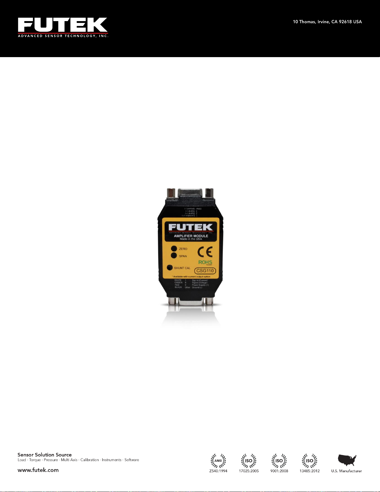
CSG110 Product Manual
Page 2

Tel: (949) 465-0900
Fax: (949) 465-0905
Toll Free: (800) 23 FUTEK
Table of Contents
Default Settings ............................................................................................................................ 3
Connections .................................................................................................................................. 3
Standard Span & Zero Adjustment ........................................................................................... 4
Shunt Readings ............................................................................................................................. 5
Switch Configurations ................................................................................................................. 5
Excitation ................................................................................................................................... 6
Polarity ...................................................................................................................................... 6
Gain ............................................................................................................................................ 7
Bandwidth ................................................................................................................................. 8
Current Setting
Advanced Span and Zero Adjustment ..................................................................................... 9
Adjusting the Zero ................................................................................................................... 9
Adjusting the Span................................................................................................................... 9
Appendix A (Noise levels) ....................................................................................................... 10
Appendix B (Specifications) ..................................................................................................... 11
(4)
...................................................................................................................... 8
- 2 -
Page 3
Tel: (949) 465-0900
Fax: (949) 465-0905
Toll Free: (800) 23 FUTEK
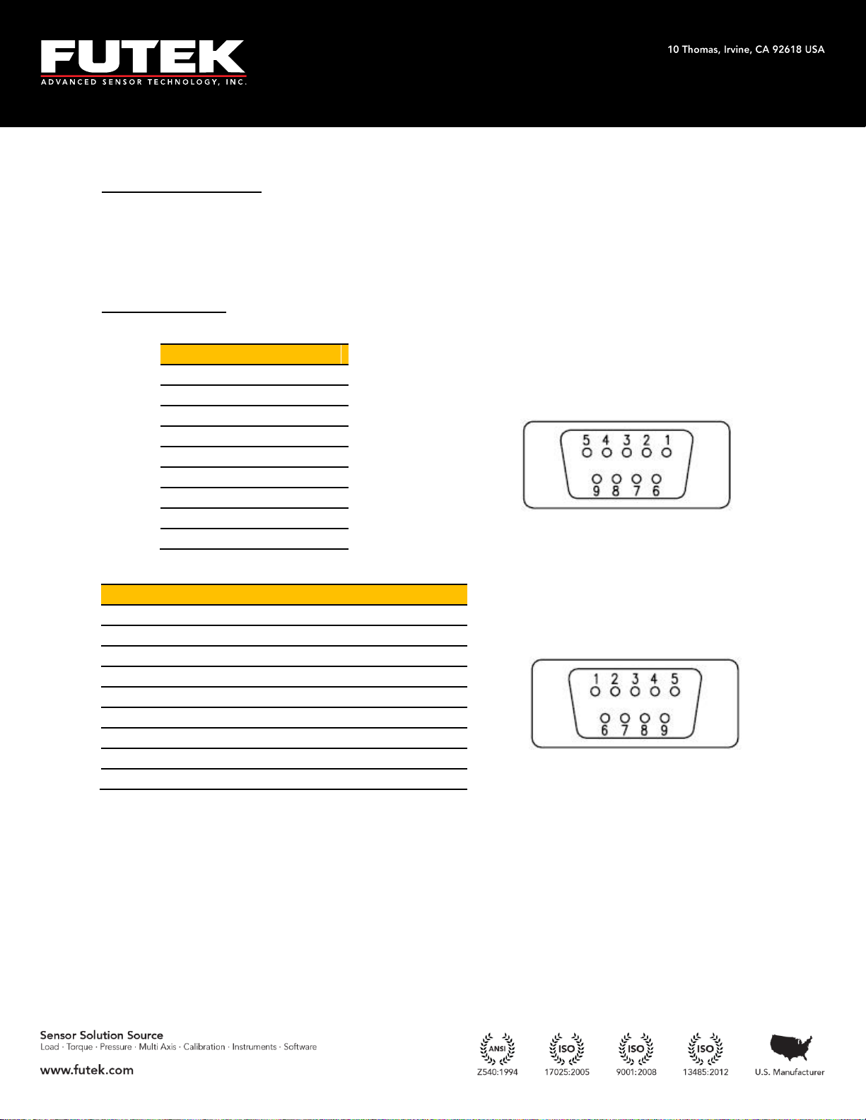
Pin
Wiring Code
1
+Excitation
(1)
2
+Signal
3
-Signal
4
-Excitation
(1)
5
Ground
6
Ground
7
Ground
8
Ground
9
Ground
Pin
Wiring Code
Cable Color Code
9
Power Supply
Red
8
Signal Out (Voltage)
Green
7
Ground
Orange
6
Ground
Black
5
Ground
N/A
4
Ground
N/A
3
Ground
N/A
2
Ground
Blue
1
Signal Out (Current)
(2)
White
Female- Sensor Side
Default Settings
Input Range: 0 to +/-2 mV/V
Excitation Voltage: 10 VDC
Output Range: +/-10 VDC, 4-20 mA
Connections
Note: Do not connect the device to the power supply when the power
supply is already on!
(1) For 6 wire sensors connect +Sense to +Excitation and –Sense to –Excitation or Ground
(2) Only available with current output option
- 3 -
Page 4
Tel: (949) 465-0900
Fax: (949) 465-0905
Toll Free: (800) 23 FUTEK
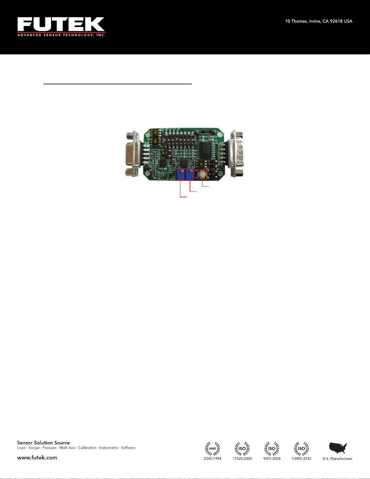
Zero
Span
Shunt
Standard Span & Zero Adjustment
Once all of the connections are complete, you can begin to set up the sensor/amplifier
system. You will need to have the output from the CSG110 connected to a device so
you can read the voltage or current.
To set up the system, follow the steps below:
1. Apply a known load to the sensor.
2. Allow the sensor to settle.
3. Use a screwdriver to adjust the span that correlates with that load.
4. Remove the load.
5. Allow the sensor to settle.
6. Adjust the zero.
Ex. If you are applying a full load to the sensor with an excitation voltage of 10 VDC,
then you would want to adjust the output (span) to 10VDC or 20mA. If you are
applying half of the full load then you would want to adjust the span to exactly half of
the maximum. Once your span is set, check the zero. With no load applied to the
sensor, adjust the zero.
Note: Adjusting the zero and span is done by using a screw driver to adjust the
potentiometers (pots).
- 4 -
Page 5

Tel: (949) 465-0900
Fax: (949) 465-0905
Toll Free: (800) 23 FUTEK
Shunt Readings
Shunt resistors simulate a load on the load cell; thus, allowing for calibration. Follow
the steps below in order to utilize the shunt feature.
1. Determine the value of the shunt resistor needed
(http://www.futek.com/shuntcalc.aspx)
2. Connect the shunt resistor in the spot labeled ‘RSH’.
3. Press the pushbutton that corresponds to the shunt.
4. While the shunt is enabled and the CSG110 is reading the simulated load, adjust
the span (described above) to the correct output.
Ex. If you are using a 2 mV/V sensor with a 350 Ohm bridge and the default 60.4 kOhm
resistor on the CSG110, then the simulated load would be approximately 72% of R.O.
You can then adjust the span to 7.2 VDC to correlate with this simulated load.
Switch Configurations
To change any of the switch configurations from the default settings, follow the tables
below to set your desired configuration. The figure below shows the default
configuration.
- 5 -
Page 6

Tel: (949) 465-0900
Fax: (949) 465-0905
Toll Free: (800) 23 FUTEK
shunt
excitation
polarity
bandwidth
gain
SW1
SW2
SW4
SW5
current setting
SW8
SW6
current input range
SW7
SW3
UP 5
DOWN 10
SW1: Excitation (VDC)
Excitation
There are two excitation values available on the CSG110: 10 VDC (default), and 5 VDC.
To select the excitation, simply flip the DIP switch to the appropriate configuration.
The excitation voltage controls the maximum output of the amplifier.
Ex. If your application requires a lower output voltage than 10 VDC, then the 5 VDC
option is available to use. All you have to do is flip the DIP switch from the down
position to the up position.
Polarity
There are two polarities available on the CSG110: reverse, and straight (default). To
select the polarity, simply flip the DIP switch to the appropriate configuration.
- 6 -
Page 7

Tel: (949) 465-0900
Fax: (949) 465-0905
Toll Free: (800) 23 FUTEK
UP reverse
DOWN straight
SW2: Polarity
Ex. If you are using your CSG110 with a tension and compression load cell and you
have tension setup as the positive direction, but now you would like to have
compression as the positive direction, all you have to do is flip the DIP switch from the
default polarity position to the reverse polarity position.
Gain
There are eight gain settings available on the CSG110: from 0.5 mV/V to 10 mV/V. The
default setting is configured to 2 mV/V. Select the value closest to your input range by
flipping the DIP switches to the appropriate configuration.
Ex. If you are using a 2 mV/V sensor with the 5 VDC excitation, then you would want to
use configuration 2 for 1 mV/V. If you are using a 2mV/V sensor with 10 VDC
excitation then you would want to use configuration 4 for 2 mV/V.
- 7 -
Page 8

Tel: (949) 465-0900
Fax: (949) 465-0905
Toll Free: (800) 23 FUTEK
1 UP 0.5 5 UP 2.5
DOWN N/ A DOWN N/ A
2 UP 1 6 UP 3
DOWN N/ A DOWN N/ A
3 UP 1.5 7 UP 4
DOWN N/ A DOWN N/ A
4 UP 2 8 UP 10
DOWN N/ A DOWN N/ A
SW3: Sensitivity (mV/V)
UP
10
(3)
DOWN 1
SW4: Bandwidth
SW5 SW6 SW7 Input Range (V)
Output Range (mA)
DOWN DOWN DOWN 0-10 4-20
DOWN DOWN UP 0-10 5-25
UP DOWN DOWN 0-10 0-16
UP DOWN UP 0-10 0-20
DOWN UP DOWN 0-5 4-20
DOWN UP UP 0-5 5-25
UP UP DOWN 0-5 0-16
UP UP UP 0-5 0-20
Bandwidth
There are two bandwidth settings available on the CSG110: 1 kHz (default), and 10 kHz.
To select the bandwidth, simply flip the DIP switch to the appropriate configuration.
Ex. If your application requires a higher bandwidth in order to account for the higher
frequency signals, such as those from dynamic applications, then you would want to
use the higher setting bandwidth.
Current Setting
(4)
There are four current output settings available on the CSG110: 0-16 mA, 0-20 mA, 4-20
mA (default), and 5-25 mA. To select the current, simply flip the DIP switches to the
appropriate configuration.
Note: Only available with current output option.
(3) 25 kHz for QSH01498
(4) Only available with current output option
- 8 -
Page 9

Tel: (949) 465-0900
Fax: (949) 465-0905
Toll Free: (800) 23 FUTEK
Advanced Span and Zero Adjustment
Adjusting the Zero
At times, when using a signal conditioner, it is necessary to offset the zero. The CSG110
makes this simple. The zero can be adjusted approximately ±10% of R.O. by using the
potentiometer on board.
Adjusting the Span
The input jumpers vary from 0.5 mV/V to 10.0 mV/V. This allows for a large variety of
input ranges. However, it sometimes happens that the rated output from the sensor is
not exactly 2.0 mV/V or 3.0 mV/V. The CSG110 has a ±10% of R.O. adjustment range
so a sensor with an output close to one of the input ranges will work fine.
- 9 -
Page 10

Tel: (949) 465-0900
Fax: (949) 465-0905
Toll Free: (800) 23 FUTEK
Current Output
Voltage Output
Bandwidth
Sensitivity (mV/V)
Current noise (µA)
Voltage noise (mV)
Voltage noise (mV)
1 kHz
0.5
151
50
30
1 151
50
25
1.5
151
50
20
2 151
50
15
2.5
151
50
15
3 151
50
15
4 151
50
15
10
151
50
15
Current Output
Voltage Output
Bandwidth
Sensitivity (mV/V)
Current noise (µA)
Voltage noise (mV)
Voltage noise (mV)
10 kHz
0.5
151
75
40
1 151
75
35
1.5
151
75
30
2 151
75
25 2.5
151
75
20
3 151
75
20
4 151
100
20
10
151
100
15
Appendix A (Noise levels)
Drawing Number: EM1000-E - 10 -
Page 11

Tel: (949) 465-0900
Fax: (949) 465-0905
Toll Free: (800) 23 FUTEK
Electrical Specifications
Parameter
Min
Typical
Max
Unit
Power Supply6
14 26
VDC
Current Draw
7
30
mA
Output Impedance (Voltage)
< 1 Ohms Ohms
Output Impedance (Current)
700
Ohms
Sensor Impedance
100
Ohms
Bandwidth
1000
25000
Hz
Common Mode Rejection Ration
120
dB
Noise 15
mVp-p
Output Span Range
-10 10
% of Rated Output
Output Zero Range
-10 10
% of Rated Output
Gain Drift with Temperature
-25 X 25
PPM of FSR per degree Celsius
Gain Non-Linearity
-0.001
X
0.001
% of FSR
Zero Drift with Temperature
-25 X 25
PPM of FSR per degree Celsius
Appendix B (Specifications)
6
Minimum Power Supply Varies for OEM Models
7
No Load Applied (Input or Output)
Drawing Number: EM1000-E - 11 -
 Loading...