

Page 1
SBS-01C
*Solder welding is required for
instruction.
LED Indication
Slot Number Setup
Reset
Function
Specication
Wiring
Every time it's used, current
consumption is added to SBS-01C.
SBS-01C does not reset even if a
connection is removed or it is turned
off.
The consumption capacity returns
to 0. When you'd like to know the
consumption capacity of 1 ight, please
reset before a ight.
*Power supply off isn't done for 5
seconds after a reset. Because data
isn't preserved.
1M23N26733
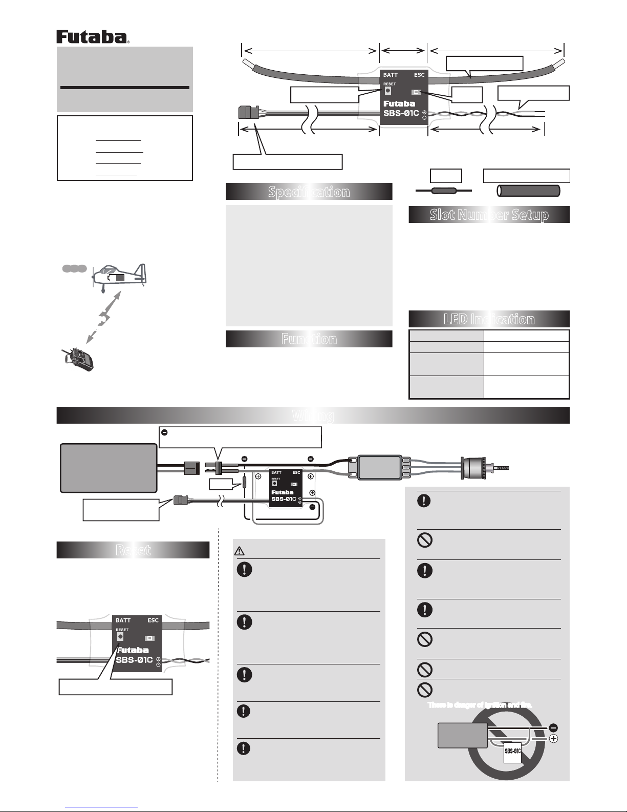
RX S.BUS2 port
Battery
ESC
80mm (3.15 in.)
200mm (7.87 in.)
80mm (3.15 in.)
21mm (0.83in.)
700mm (27.6 in.)
Reset switch LED
Voltage cable
Fuse
< parts >
Heat Shrink Tube
Fuse
To S.BUS2 port of
telemetry receiver
To S.BUS2 of receiver
Current cable
80mm (3.15 in.)
21mm (0.83in.)
Press the reset switch
Wiring and connector are not attached.
Use a connector with no electrical power loss.
Use : Current sensor
Detection item:
Current (0A ~ 150A)
Voltage (0V ~ 70V)
Consumption capacity (0mAh ~ 32767mAh)
*Measurement is impossible less than 1A (Current).
Weight:23g(0.81 oz.)
Voltage : DC 3.7V ~ 7.4V
Current : 0A ~ 70A
70A ~ 150A (within 10 seconds)
Please note that the proper default slot for
this accessory is number 24. This sensor
uses 3 slots, starting at 1, 2, 3, 4, 5, 8, 9,
10, 11, 12, 13, 16, 17, 18, 19, 20, 21, 24,
25, 26, 27, 28, 29. Information on how
to change the slot assignment is included
in the transmitter's manual.
Telemetry current sensor
Instruction Manual
Thank you for purchasing Futaba's
SBS-01C Current Sensor. Please
read this manual thoroughly to
ensure proper current sensor
performance. We also encourage
you to retain the manual for future
reference.
WARNING
To utilize the SBS-01C, connect it
to the S.BUS2 port of the Futaba
telemetry enabled receivers.
■ The SBS-01C will not function properly if
connected to an S.BUS port or other channel
ports.
Ensure that the unit is mounted in
an area that will eliminate
exposure to fuel, water and vibration.
■ As with any electronic components, proper
precautions are urged to prolong the life and
increase the performance of the SBS-01C.
Allow a slight amount of slack in
the SBS-01C cables and fasten
them at a suitable location to prevent
any damage from vibration.
Connect the connector polarity
properly.
■ If connected in reverse, explosions or fire
could occur.
Insert the connector securely.
■ If the connector works loose during
model operation, control will be lost and
cause the potential for extreme danger.
Green Normal operation
Red No signal reception
Green/Red
When setting up the
slot
Green/Red
Alternate blink
Unrecoverable error
● Telemetry data:
The SBS-01C can monitor and display
the in-flight current, voltage, and current
consumption of the drive battery.
●Applicable systems
Futaba T18MZ -WC
Futaba T18MZ V2.6 ~
Futaba T18SZ V1.4 ~
Futaba T4PX V1.4 ~
Can be checked at
the transmitter.
(May, 2016)
● Current
● Voltage
● Consumption capacity
Drive Battery
Battery
Battery
The SBS-01C should be mounted
away from magnetic bodies.
■ If close to a magnetic body, the DC current
may not be measured correctly.
Do not install the SBS-01C in a
ammable location.
■ There is danger of ignition and fire.
To ensure that the SBS-01C is
functioning as desired, please test
accordingly.
■ Do not use until inspection is complete.
Be careful the battery Lost.
■ The consumption capacity is indicated.
(It isn't the present battery capacity.)
Don't apply current higher than
rated current to SBS-01C.
■ SBS-01C may break down and fall.
Do not use the SBS-01C with
anything other than R/C models.
Never connect current cable
during +- of a battery.
■ There is danger of ignition and fire.
Page 2
ESC
Voltage cable
①
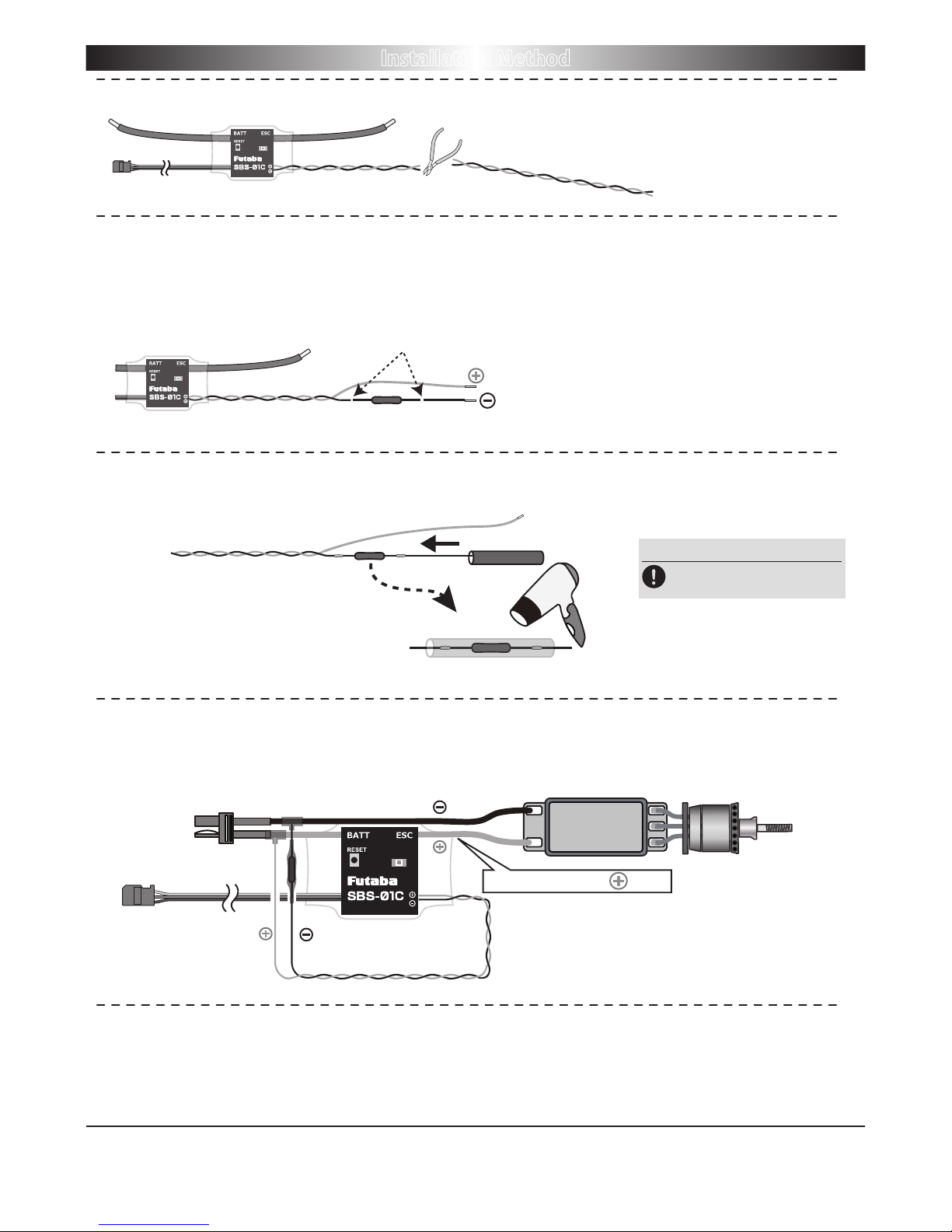
Measure the cable and then cut it to the desired length.
②
Cut approximately 30mm of the black
(-)
line from the cable.
Solder the fuse inline on the black
(-)
wire and then reattach the section of wire
that was previously removed. The fuse should be attached as close to the
external power supply as possible.
③
Place a piece of heat shrink tubing over the fuse, ensuring that it covers the
soldered areas. Shrink the tubing snug to the fuse and the wire using a heat gun.
④
The cable should be connected as shown in the diagram below.
⑤
The manual for the Telemetry system should be referred to after the setup is
complete. Check to make sure it functions as desired and that it provides the
correct data on the display.
The fuse should be attached as close to the
external power supply as possible.
Heat shrink tube
Fuse to Black line (-)
Heat shrink tube
Heat shrink
The connection is affixed to the ESC on the wires
that are connected to the battery by soldering them
and then protecting them with heat shrink.
To Power Battery
SBS-01C on the line.
Fuse(mount in either direction)
Fuse
Solder welding
Installation Method
WARNING
Be careful to avoid burns from
high-temperature work.
FUTABA CORPORATION
1080 Yabutsuka, Chosei-mura, Chosei-gun, Chiba-ken, 299-4395, Japan
Phone: +81 475 32 6982, Facsimile: +81 475 32 6983
©FUTABA CORPORATION 2016, 5 (1)
 Loading...