

Page 1
FP-6FN 6ch. FP-5FN 5ch.
FP-4FN 4ch. FP-3FN 3ch.
Page 2

INDEX
Features
Composition and Specifications
Transmitter
Receiver
FUTABA trainer
Operating instructions
Nickel-cadmium battery and charging methods
Performance test and mounting precautions.....................
FUTABA proportional
Guarantee.....................................................................
Factory repair service
.....................................................................
....................................
handling
and
instructions
servo
handling instructions
system
................................................
...................................................
frequencies
...................................................
....................................
........................
...............
.................................
Page 3

FEATURES OF THE NEW FUTABA PROPORTIONAL
RADIO CONTROL SYSTEM
TRANSMITTER (FP—T6FN. FP—T5FN. FP—T4FN, FP—T3FN)
1. Since all Futaba New Proportional Models are designed and manufactured to identical standards, maximum
performance is displayed even when used with other receivers and servos.
2. Position of throttle control can be easily changed (to left or right).
3. Hook band permits hanging the transmitter from your neck for extremely easy handling.
4. Training system provided as standard makes training of beginners easy.
5. Equipped with a stand.
RECEIVER (FP—R6F. FP—R4F, FP—R3F)
1. Newly developed receiver use FUTABA CUSTOM 1C (IR-014, or BA-633) is extremely stable against power supply
voltage fluctuations.
2. Eight-bit CMOS 1C has complete 6-channel operation functions and reduces power consumption to a minimum.
3. Resistance against interference has been strengthened considerably through the adoption of a RF amplifier circuit
and ceramic filter.
SERVO (FP—S7. FP—S12. FP—S16. FP—S16L. FP—S17, and FP—S8, FP—S16G
[retractable landing gear servo])
1. Since the FP-S7, FP-S12, FP-S16, FP-S16L, FP-S17, and FP-S8, FP-S16G (retractable landing gear servo) are
designed and manufactured to the same standards, top performance is displayed when used with any NEW
FUTABA PROPORTIONAL transmitter and receiver.
2. Three-wire, compact, lightweight, rugged, high-output torque servoamps have been realized through the use of
Futaba BA-607 and BA-606 custom monolithic 1C.
3. The BA-607 monolithic 1C is a 12-pin single-end-line 1C containing 73 transistors, 13 diodes, and 79 resistors (total
of 165 components). Its low current drain, high resolution, temperature compensation and built-in voltage regulator
assure stable operation over the 4V— 6.6V power supply voltage range without any mutual interference between
servos. A
Page 4

4. The BA-606 monolithic 1C is a 9-pin single-end-line 1C incorporating 2 high output current (500mA)
sistors, 2 NPN transistors, 4 diodes, and 4 resistors for a total of 12 components on a single chip.
5. High output torque: FP-S7; 3 kg-cm, FP-S12; 2.8kg-cm, FP-S16 (S16L); 2kg-cm, FP-S17; 2.6kg-cm, and FP-S8,
FP-S16G (retractable landing gear servo); 8kg -cm, 2.6kg -cm.
6. Compact, lightweight: FP-S7; 48g, FP-S12; 52g, FP-S16 (S16L); 41 g, FP-S17; 44g, and FP-S8; 50g, FP-S16G; 41g.
7. The 20mm (dia.) motor of the FP-S7 servo provides power torque. Thus making it ideal for
use. Waterproof case also makes it perfect for use in both fresh water and salt water areas.
8. FP-S12 is a low cost servo and powerful torque of 2.8kg -cm or greater permits use not only in large buggies,
but also in Class 60 boats, etc.
9. The potentiometer drive section of the FP-S16 (S16L) is separately driven through a one-stage gear. The life of
the element is almost permanent.
10. FP-S17 is a lightweight, rugged, high output, and low cost servo.
11. The high gear ratio and powerful torque of the FP-S8 make it the perfect retractable landing gear servo.
12. FP-S16G is a highest class miniature landing gear servo.
boat and automobile
PNP
tran-
COMPOSITION AND SPECIFICATIONS
• COMPOSITION:
Transmitter/receiver nickel-cadmium battery
Model
Number of channels
Transmitter
Receiver
Servo
Battery charger
PP-6FN
6CH
FP-T6FN
FP-R6F
FP-S16 x 3
FP-S16Lx1
FP-5FN
5CH
FP-T5FN
FP-S16x3
FP-S16Lx1
Nickel-cadmium charger FBC—2(F)
FP-4FN
4CH
FP-T4FN
FP-R4F
FP-S16x3
FP-S16Lx1
FP-3PN
3CH
FP-T3FN
FP-R3F
(FP-S7 x 2
FP-S16 x 2 FP-S12x2
FP-S17 x 2)
Page 5

• SPECIFICATIONS:
Operating system......... CH1—4, 2-stick system, CH5 snap
Operating frequencies... 27MHz band 72MHz band
Antenna output............
Modulation
system
......
Power requirement......
Current drain............... 140mA
Receiving frequencies... 27MHz band 72MHz band
IF amplifier frequency... 455kHz
Selectivity
Range
..................
........................
Power requirement...... 4.8V 4/450mAH nickel-cadmium
Current
drain...............
Dimensions
...............
Weight........................ FP-R6F:
(All
specifications
are
TRANSMITTER
switch, CH6 trim lever system
40 MHz band
500mW
AM
(amplitude
modulation)
Pulse position modulation:
1310uS neutral (Pulse spacing)
9.6V 8/450mAH nickel-cadmium
battery
RECEIVER
40MHz band
3kHz/-3dB
500m
on
the
ground,
1000m
battery
4.8V 10mA
FP-R6F:
40
x69
FP-R4F,
R3F:
x19mm
40.2x58.5
52g
FP-R4F. R3F: 46 g
subject
in the air
x19mm
to change
without
prior
notice.)
SERVO (FP-S7, FP-S12, FP-S16, FP-S16L,
FP-S17, FP-S8, FP-S16G)
Control
system
............
3-wire, + pulse
width control
650uS~ 1900uS
Operating angle............
Rotary system one side 45° min
(including trim) FP-S7. FP-S12,
FP-S17
Rotary system one side 80° min FP-S8.
FP- S16G (retractable landing gear servo)
Power requirement...... 4.8V 4/450mAH nickel-cadmium battery
(used in conjunction with receiver)
Current
drain...............
Output torque ............
4.8V
8mA
(when
stopped)
FP-S7; 3kg-cm, FP-S12: 2.8 kg-cm,
FP-S16; 2kg-cm, FP-S17: 2.6kg-cm,
FP-S8: 8 kg-cm, FP-S16G: 2.6 kg-cm.
Dimensions.................. FP-S7:
23 x 44 x 41 mm.
FP-S12: 23 x 44.5 x 42.5 mm,
FP-S16:19.5x41 5x35.5mm,
FP-S17: 20 x 39.6 x 40 mm,
FP-S8; 23x44x41 mm,
FP-S16G: 19.5 x 41.5 x 35.5 mm
Weight........................ FP-S7:
48g,
FP-S12;
52g,
FP-S17; 44g. FP-S8: 50g, FP-S16G; 41g.
BATTERY CHARGER (Nickel-cadmium charger)
Input
voltage
Frequency
...............
..................
115V
(220V,
50/60Hz
240V)
Power consumption ... 2.0/3.5VA
Output
Tx.
Output
..................
NOTE:
Power consumption is for no load/load. Since the transformer may be burned up or the performances of the battery will deteriorate due to
an
overcurreni if the NR-4C nickel-cadmium battery is connected to the Tx output terminals, always be sure that connections are correct.
Rx................... 4.8V, 45mA
9.6V, 45mA
FP-S16.
FP-S16;
41g,
Page 6
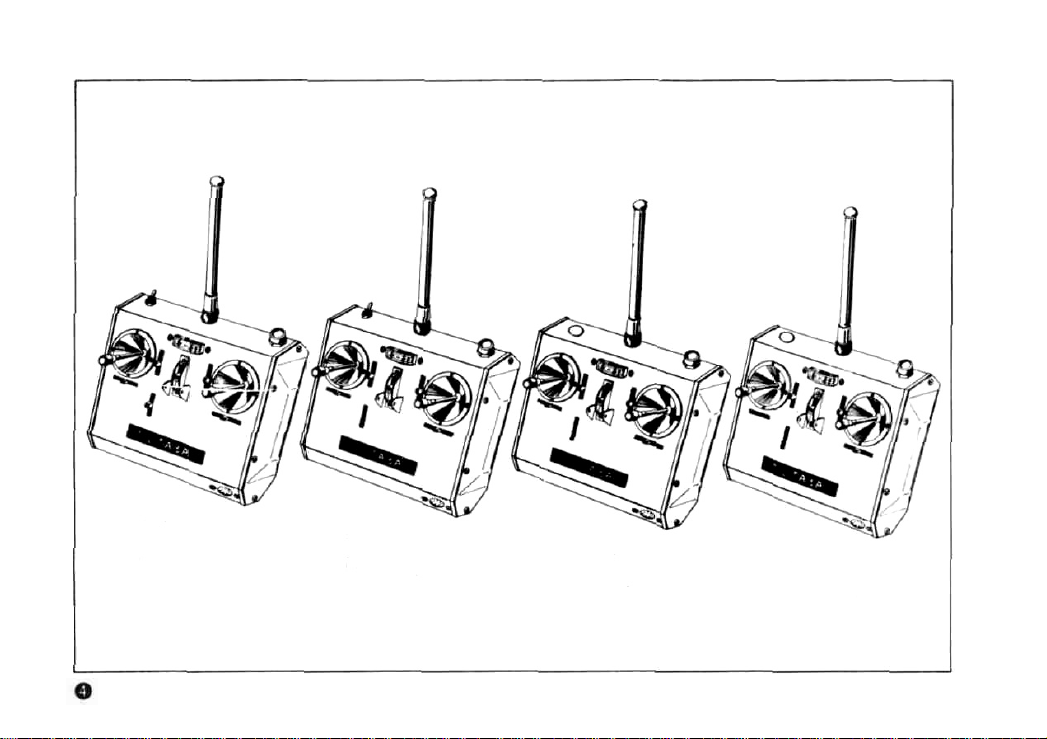
TRANSMITTER HANDLING INSTRUCTIONS
FP T6FN
(forFP -6FN)
6 CHANNEL
FP-T5FN
(tor
FP-5FN)
5-CHANNEL
Fig.
FP-T4FN
(for
FP
4FN)
4-CHANNEL
1
FP-T3FN
(for FP-3FN)
3-CHANNEL
Page 7

The controls on the front panel of the transmitter are shown in
Fig. 2. The manipulation of these controls should be thoroughly
mastered.
Throttle
(MODE 1: Elevator)
AUX Lever
(6TH CHANNEL)
Snap switch
(5TH CHANNEL)
Rudder
FP-T6FN
NORMAL
Trainer switch
Trainer cord socket
Fig.
2
Servo rotates in
the forward direction
when moved in the
direction of the thick
arrow (*).
Elevator
(MODEL Throttle)
Aileron
FP-T4FN (FP-T3FN)
The (1) engine, (2) ailerons, (3) elevator,
and (4)* rudder can be controlled with the
sticks at the left and right.
Transfer between transmitters is possible
with (5) trainer switch by connecting to
another transmitter with the trainer cord.
* FP-T3FN doesn't have (4) rudder above.
FP-T5FN
The landing gear or other suitable operations can be performed by means of the
snap switch, in addition to the 4 operations
mentioned above.
PP-T6FN
The flaps, etc. can be operated by means
of a potentiometer, in addition to the 5
operations described above.
• Select either the long or short left and
right stick knob, whichever is the easiest
to use.
The knob can be replaced by merely pulling off the black knob.
• Hook the neckstrap to the hook and hang
the transmitter from your neck.
Page 8

1. The
FP-3FN, FP-4FN, FP-5FN, FP-6FN each use a built-in nickel-cadmium battery (8/450 mAH) as the transmitter
power source.
2. Mount the antenna securely and set the power switch to the ON position . The pointer of the meter will deflect
to within the green zone. This indicates that the radio waves are being radiated. If the meter pointer fails
to
deflect, check for a faulty connection in the power supply.
3. If the meter pointer deflects to within the red zone, the nickel-cadmium battery is low and must be recharged. A special charger is provided.
4. Note that the range of the radio waves will become shorter when the meter pointer deflects to within red zone.
5. The "trim" lever of each stick is used for fine adjustment. These levers are used for neutral adjustment of each
rudder and to adjust the flying posture after mounting in the fuselage.
6. Open the stand at the rear cover when setting up the transmitter. This stand can be used as a handle by
raising it to the topmost position. This is extremely convenient when carrying the transmitter.
Page 9

RECEIVER AND SERVO HANDLING INSTRUCTIONS
XTAL ... Crystal
AUX2 ... For 6CH Tx: Snap switch
AUX1 ... For 6CH Tx: Lever type switch
For 5CH Tx: Snap switch
RUDD ... Rudder (FP-3FN doesn't have
ELEV ...Elevator
THRO ... Throttle
AILE ... Aileron
8ATT ... Power supply
(FP-3FN doesn't
FP-R6F
WHITE
RED
have rudder)
1. The FP-R6F receiver employs an 8 bit 1C and has been especially designed for 6 channel use. (Combined 5
channel, 6 channel use.)
2. The block connectors which connect the receiver to each servo form a single unit with the receiver.
3. Connect to the servos by verifying the block connector connection positions stamped on the receiver case. Use
the white relay connector for the ailerons. Be sure to use the 3P white connector from the switch harness for
the power supply (BATT).
rudder)
Fig.
3
Page 10

4. Since all the servos are manufactured to the same standards, any servo can be used for any purpose.
5. The FP-S6L (reversible servo, red label) in the set can be conveniently used for throttle control with high wing
and middle wing airframes.
6. Connection methods are illustrated in Figure 3. Be sure that each connector is plugged in fully and that the
power supply switch harness, aileron section, etc. are connected correctly.
7. After verifying that all connections are correct by checking them against the connections given in Figure 3, turn
the transmitter power switch on. Then turn the receiver switch on. At this time, each servo will stop at the
neutral position.
8. Operate sticks and trim levers and verify that respective servos operate positively.
9. When testing each section, be sure that the transmitter and receiver antennas are fully extended. If the transmitter antenna is short and the power switch is left on for more than 5 minutes, the transistors inside the
transmitter will be damaged.
10.
If the system fails to operate after the transmitter, receiver, servos, switch harness, and batteries have been
properly installed, the problem may be due to damage during shipment. Do not attempt to open any of the
unit, but return them for replacement.
Page 11

FUTABA TRAINER SYSTEM
•The
NEW FUTABA PROPORTIONAL
newly developed FUTABA Trainer System as standard. This system prevents damaging of valuable aircraft by
beginners. Use this system with a veteran as your teacher. A special trainer cord is available as an option.
• The FUTABA Trainer System can be used without regard to frequency (27MHz, 40MHz, 72MHz) or number of
channels of the instructor's transmitter and students transmitter. For instance, the 27MHz FP-T6FN can be
used with the 72 MHz FP-T4FN. However, in this case, use the 27MHz FP-T6FN as the instructor's trans-
mitter if the frequency of the receiver is 27MHz and use the 72MHz FP-T4FN as the instructor's transmitter if
the frequency of the receiver is 72MHz. Naturally, the number of operable channels corresponds to that of the
transmitter. The above is an example of 4 channel operation.
Transmitters
FP-T4FN.
FP-T5FN,
and
FP-T6FN
are
equipped
with
the
OPERATING INSTRUCTIONS
1. When conducting training, connect the two transmitters together with the special cord*as illustrated in Figure 4.
*Similar cords are on sale, but since these cannot be used, always use the special FUTABA shielded trainer
cord.
2. The instructor must use a transmitter of the same band as the receiver. (The instructor's transmitter is designated
Tx1 and the student's transmitter is designated Tx2.)
Since the radio waves are always radiated from the Tx1 side (transmitter whose power has been turned on),
extend the antenna of Tx1 fully. The position of the antenna of Tx2 doesn't matter, since the radio waves are
radiated from Tx1 even when operation is performed from Tx2.
3. Turn on the power of Tx1 only. The meter pointer will deflect, the same as for the case of independent operation.
The meter pointer of Tx2 will also deflect simultaneously.
NOTE: Never turn the power switch of Tx2 on, regardless of whether the bands coincide or not.
Page 12

4. When the trainer button of Tx1 is depressed,
radio waves will be directly radiated from
Tx1, but the control operation is shifted to
Tx2. Consequently, the student can exercise
control only during the period the instructor
is depressing the trainer button. When the
instructor releases the button, he can exer-
cise direct control over all operations.
5. Perform neutral adjustment of the other
transmitter on the ground before beginning
actual flight. Adjust the trim of both transmitters so that the rudder servos are not
operated when the trainer button is depressed.
6. Since power is supplied from Tx1 even when
the student is operating, the current drain of
Tx1 will be about 10% greater than when
used independently.
7. Deflection of the meter will become small
when the trainer cord is connected, but this
is normal.
Switch ON
Trainer switch
Instructor
Transmitter
Switch
OFF
Trainer cord socket
Special trainer cord
Tx1 (Instructor side: Transmitter combined with receiver.)
Tx2 (Student side)
Fig.
4
Student Transmitter
Page 13

NICKEL-CADMIUM BATTERY AND CHARGING METHODS
• The FP-T3FN, FP-T4FN, FP-T5FN, and FP-T6FN transmitters are each equipped with a built-in nickel-cadmium
battery (8/450 mAH) power supply.
• Use a nickel-cadmium penlight cell (4/450mAH) as the receiver and servo power supply.
• Charge the nickel-cadmium battery for 12~15 hours before normal use. Charge the battery for 20 hours when
it has not be used for an extended period of time. Slight overcharging will cause no harm to the battery.
• A fully charged nickel-cadmium battery can normally be used about 10 times at a 10 minutes/time rate.
• The nickel-cadmium battery will supply a uniform voltage for a certain period of time, but pay careful attention
to the voltage after being used 7~8 times.
Connect the battery charger supplied with the FP-3FN, FP-4FN, FP-5FN, and FP-6FN as illustrated in Figure 5.
AC-115V (220V, 240
FBC-2 (F)
Tx
Rx
NR-4C
Fig.
5
Page 14

Receiver
WHITE
NiCd Battery
Charging plug
The 3P red female connector of the switch harness is used to charge the NR-4C (receiver and servo use NiCd
battery) without removing it from the model.
To
charge the NR-4C (receiver and servo NiCd battery) without removing it from the model, set the switch to
the OFF position and connect the 3P red male connector from the charger to the 3P red female connector of
the switch harness.
Charger (RX)
Page 15

1. The cord with the power plug at both ends is the Tx charging use cord. To charge the transmitter, connect
this cord to Tx of the charger and "A" of the transmitter.
2. The cord with the power plug at one end and the 3P connector at the other end is the RX charging use cord.
When charging the NR-4C receiver use nickel-cadmium battery, connect the power plug end of this cord to
RX of the charger and the 3P connector end to the NR-4C.
3. Plug the charger plug into an AC line receptacle (AC 115V, 220V, 240V).
4. Charging is performed with the above operations. At this time, the LED of the charger will be illuminated to
indicate that charging is being performed.
5. Be absolutely sure that all the connections are correct. If the NR-4C receiver use nickel-cadmium battery is
connected to Tx, the battery may be damaged by overcharging.
6. The special charger can charge the transmitter battery and receiver battery simultaneously or independently.
PERFORMANCE TEST AND MOUNTING PRECAUTIONS
1. Verify that the receiver and servos are connected in accordance with Figure 3. Then, make the transmitter
antenna
as
short
as
possible and
30m. Operation is normal if all the controls are functioning properly. Perform this test within a maximum of
5 minutes time. Never perform this test when the transmitter antenna is not mounted to the transmitter. Otherwise the transmitter will be adversely effected.
2. Be careful that the receiver does not directly touch other mechanisms of the aircraft itself. Moreover, wrap the
receiver in sponge rubber so that it is not subjected directly to engine vibrations. (In the case of boat use, cover
the sponge wrapping with a vinyl bag and tie securely at the point at which the cord enters so that no water can
enter the receiver.)
extend
the receiver antenna and attempt operation
from a distance of
20m~
Page 16

3. The use of a servo tray is extremely convenient when installing the servos. The method of installation is
illustrated in the figure. (Insert each connector fully.) Don't forget to confirm that the motion of the servo horns
and rods matches the direction of operation of the transmitter sticks. Use the reversible servo (L servo) as a
shoulder wing throttle servo or for rudder and nose gear operation.
• NOTE; The L servo cannot be used for aileron control. (The operation of the stick and rudder are opposite.)
2.6x6
2.3»18
TYPE"H"
Fig.
NORMAL
(TO COUTER-
CLOCKWISE]
REVERSE
(TO CLOCKWISE)
STICK TO RIGHT
Pig.
6
TYPE"V
7
Page 17

4. After setting the push rod at each servo, operate each servo fully left and right at least once. If the rod catches
or sticks at this time, the servo has been damaged by an overcurrent. Therefore verify that the rods are
functioning perfectly.
5. Be especially careful of noise signals. For instance, noise signals will be generated by the contact of metal
against metal due to engine vibration. If these noise signals are received at the receiver, the receiver may operate
erroneously. Therefore cover one of the metal surfaces with insulating material.
6. After installation is complete, ask a nearby radio control expert or the dealer where the equipment was purchased
to instruct you on the proper handling techniques and other items which may require special attention. Also
have your installation thoroughly checked at this time.
Strict observance of safety rules and adherence to the advise of experts will make radio control more enjoyable.
FUTABA PROPORTIONAL FREQUENCIES
(Available in MHz. Available Futaba pair crystal Tx/Rx)
27 MHz Areas
26.995 (Brown)
27.045
(Red)
27.095 (Orange)
27.145 (Yellow)
27.195 (Green)
Remarks: Mark * — Model Aircraft use only.
72 MHz Areas
• 72.080 (Brown/White)
72.160 (Blue/White)
• 72.240 (Red/White)
72.320 (Violet/White)
• 72.400 (Orange/White)
72.960 (Yellow/White)
• 75.640 (Green/White)
Page 18

GUARANTEE
Your NEW FUTABA Digital Proportional R/C system is guaranteed against defects in workmanship and material for 180 days from the date of purchase when
the attached registration card is returned to us within ten days of purchase.
This Guarantee is null and void if the R/C system has been improperly handled,
damaged in a crash, or tampered with and does not cover the replacement of
plastic housings or electronic components damaged due to the use of improper
voltages.
When service is required, please take your equipment to your local authorized
service station or ship it directly to us. All postage, shipping, and insurance
charges must be paid by the user.
This guarantee only applies to the continental U.S.A., Hawaii, and Alaska.
Page 19

FACTORY REPAIR SERVICE
To insure prompt service, please follow the instructions given below.
1. Charge the batteries for at least 18 hours prior to shipment.
2. Return the system, only. Not your complete installation.
remove the foam padding from the receiver.
3. Plugs or other modifications which interfere with factory test procedures will be returned to factory
standard at your expense.
4. Carefully pack all components individually, using sufficient packing material to prevent damage
during shipment.
5. Include a brief but thorough explanation of all problems and service required and tape it to the
back of the transmitter. Place a label describing the functions of the servo on each servo.
6. Be sure to include your full address and zip code inside the box as well as on the outside.
7. Include a packing list of all items being returned, and double check to make sure that all items
are packed.
8. Upon receipt of damaged equipment at the FUTABA factory, an estimate of the cost of repair will be
sent to you. Your equipment will then be repaired and returned to you upon receipt of payment.
This factory repair service applies only to the continental U.S.A., Hawaii, and Alaska.
Remove the servos from their mounts and
Page 20

FUTABA
630 CAROB
Phone:
(213)537-9610
FUTABA
Tokyo Office: Daido
Phone: (03) 255-5881 Telex:J26532
STREET,
•
Bldg.
CORPORATION
COMPTON
CORPORATION
3-1-6 I 16,
OF
AMERICA
CALIFORNIA
Sotokanda.
Chiyoda ku.
90220
U.S.A.
Tokyo.
Japan
Printed in Japan 781020 cc
 Loading...