

Page 1
Futaba
DIGITAL PROPORTIONAL
RADIO CONTROL
INSTRUCTION MANUAL
FM
D60400
Thank you for purchasing a Futaba digital proportional
radio control set.
Please read this manual carefully before using your set.
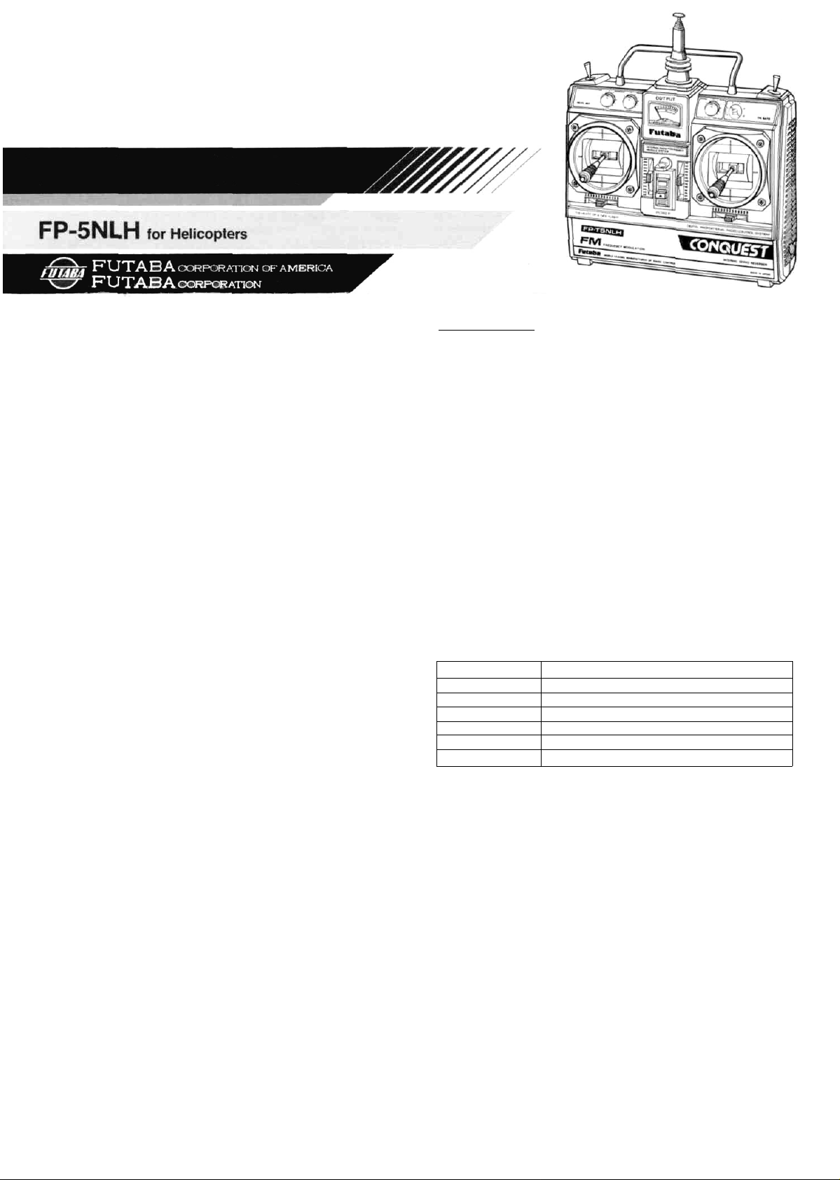
FEATURES OF FP-5NLH
The FP-5NLH for helicopters is an FM proportional radio con-
trol
set
for helicopters
result of the exhaustive pursuit of easier operation. Newly de-
signed sticks for smooth and positive operation, servo revers-
ing switches for all channels, aileron and elevator AST (Ad-
justable
Servo
Throw),
innovations based on the opinions of many RC modelers.
TRANSMITTER FP-T5NLH
• Reliability substantially improved by using industrial robots to assemble the PC board.
• Servo reversing switch for each channel. Servos are reversed by using
this switch
• Aileron and elevator AST (Adjustable Servo Throw). Servo throw can
be set as desired.
• Easy-to-adjust two knob type revolution mixing. Throttle pitch con-
trol rudder mixing.
• Pitch control trimmer. Approximately 30% of the pitch control servo
throw can be trimmed, this allows optimum pitch control of the
model.
• Throttle hold switch and trimmer for auto rotation.
• This allows the Rotor r.p.m. to maintained at an effective control
speed, even when the pitch is reduced, allowing maneuvers which
were impossible in the past to be performed.
• Newly designed open gimbal sticks operate smoothly and reliably.
Spring tension mechanism allows adjustment of the operating feel of
the stick lever.
• Nonslip adjustable lever head allows adjustment of the stick length as
desired.
• Throttle ATL. Adjustable throttle limiter type throttle trim. As the
high
side
does
convenient when connecting the linkage, etc.
• RF PC board module system.
• Functional case, created as a result of the exhaustive pursuit of easier
operation, has evolved a thick case which fits into the palm of the
hand.
• Square level meter at the transmitter indicates the power supply
voltage.
• Excellent radiation efficiency, strong 8-stage telescoping antenna.
• Neck strap bracket provided as standard. Operation is easier if the
transmitter is hung from your neck by using the optional neck strap.
• Built-in NiCad battery.
not
RECEIVER FP-R107N
• Compact, high performance FM 7-channel receiver with PC board
space reduced to a minimum.
•Special IF amp for radio communications improves the effective
receiving range stability.
• Narrow band ceramic filter improves rejection of adjacent channel
interference.
• Futaba original squelch circuit reduces erroneous operation by weak
signals (when passing a dead point, etc.) and erroneous operation by
natural noise when no signals are being received.
• Large capacitor copes with voltage changes when a battery is used.
• Vibration-resistant pin connectors.
• Fiberglass epoxy PC board with thru-the-hole plating is vibration and
shock resistant.
change
with
pitch
even
an
ergonomic
control
when
the
trim,
trim
case
crested
idle up,
is
altered,
and
it
as
other
is
very
a
SERVO FP-S130
SMALL, RUGGED, HIGH NEUTRAL SERVO
• Small, double ball bearing, water-tight & dusttight servo. High output
torque 55.6 oz-in (4kg-cm), high-speed 0.24sec/60°
• New indirect drive potentiometer improves vibration and shock resistance and neutral accuracy.
• Futaba low-power custom 1C provides extremely high torque, narrow
dead band, and superior tracking.
• Fiberglass reinforced PBT (polybutylene terephthalate) injection
molded servo case is mechanically strong and invulnerable to glow
fuel.
• Strong polyacetal resin ultra-precision servo gear features smooth
operation, positive neutral, and very little backlash.
• Fiberglass reinforced epoxy resin PC board with thru-the-hole plating
improves servo amp vibration and shock resistance.
• Three pin connector eliminates faulty contact and improves reliability
against vibration and shock. Housing has a reverse insertion prevention mechanism.
• Special grommet simplifies mounting of the servo and has an excellent cushioning effect.
• Six special adjustable splined horns.
SET CONTENTS AND RATINGS
(Specifications are subject to change without prior notice.)
FP-5NLH
PCM
Transmitter
Receiver
Servo
NiCad battery
Switch
Others
TRANSMITTER FP-T5NLH
Operating system
Transmitting frequency
Modulation system
Power requirement
Current drain
RECEIVER FP-R107N
Receiving frequency
Intermediate frequency
Power requirement
Current drain
Dimensions
Weight
Receiving range
SERVO FP-S130
Control system
Operating angle
Power requirement
Current drain (IDLE)
Output torque
Operating speed
Dimensions
Weight
FP-T5NLH x 1
FP-R107N x 1
FP-S130 x 4
NR-4J x 1
SSW-J
Charger, Ribbon, Spare horn. Mounting screw.
2 stick, 5 channels w/servo reverse, aileron
and elevator AST, helicopter mechanism
72MHz band.53MHz band
FM (Frequency modulation)
9.6 volts NiCad battery (NT-8LP)
170mA (at 12V)
72MHz band .53MHz band
455kHz
4.8V, NiCad battery (common use with servo)
13.5mA (4.8V reception)
1.38 x 2.42 x 0.8 in (35.2 x 61.7 x 20.3mm)
1.55oz (43g)
550 yards (500m) on the ground, 1,100 yard
(1000m) in the air. [FP-T5NLH]
(at the best conditions)
+pulse width control
One side 45° or more (at idle)
4.8V (Shared with receiver)
5.0V,
8mA
55.6 oz.in (4kg-cm)
0.24sec/60°
1.52 x 0.77 x 1.36 in (38.5 x 19.5 x 34.5mm)
1.47oz (42g)
Page 2
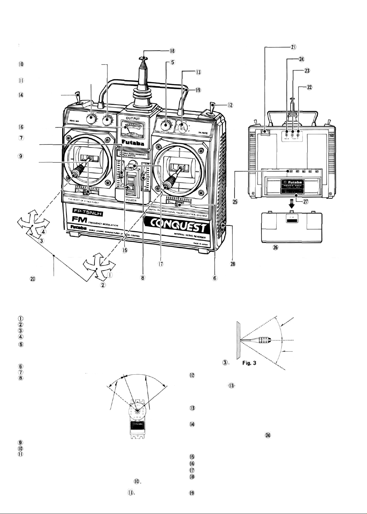
TRANSMITTER FP-T5NLH CONTROLS
Fig. 1 shows the name of each part of the transmitter.
Memorize the position and operation of each
switch and control.
Revolution mixing down knob
Revolution mixing up knob
Idle up switch
Level meter
Throttle trim
lever
Rudder trim
lever
Antenna
Pitch control trimming knob (CH5)
Throttle hold trimmer
Carrying bar
Throttle
hold switch
Transmitter crystal
Idle up trimmer
Elevator AST
trimmer
Aileron AST
trimmer
Rudder
Throttle
Power
Aileron
Elevator
knob
sides.
switch
(down
side
Exclusively
Servo throw
knob)
MODE II
Nonslip
adjustable lever head
In the following descriptions, all the servo reversing switches
are assumed to be in the normal position. When they are in the
reverse position, operation is the opposite of that described.
Aileron Aileron operation
Elevator Elevator operation
Throttle Throttle operation
Rudder Rudder operation
Pitch control trimming knob (CH5)
Pitch control trimming knob. Approximately 30% of the full throw
of the servo can be adjusted and set. Normally, it is set for the best
pitch during flight.
Aileron trim lever Aileron trimmer.
Elevator trim lever Elevator trimmer.
Throttle trim lever w/ATL
Adjustable throttle limiter
type
trim
lever.
a trim lever only when the
throttle stick is at the
SLOW side as shown in
Fig.
2.
As the HIGH side does not
change even when the trim
is altered, it is extremely
convenient when connect-
ing the linkage, etc.
Rudder trim lever Rudder trimmer.
Revolution mixing down side ratchet
Revolution mixing up side ratchet knob (up side knob)
• Knob which adjusts the throttle rudder mixing amount. Approximately 70% mixing
clockwise rotation.
The LOW side mixing amount from mid throttle (hovering point)
position is adjusted and set with the down side knob
The HIGH side mixing amount from mid throttle (hovering point)
position is adjusted and set with the up side knob
Operates
at
the up and
SLOW
as
Servo throw by
throttle trimmer
(30% of full throw;
Throttle servo
down
Neck strap bracket
Throttle trim
lever s/ATL
HIGH
by throttle
stick
Fig. 2
for
rotor
Servo reversing
switches
Transmitter
NiCad battery
NT-8LP
Battery cover
Charging jack
Aileron trim lever
Mixing circuit is used for cancelling the torque reaction of the main
rotor. The controls for set the minimum mixing necessary for helicopter flight.
• The amount of the
revolution mixing
up side knob 11
and down side
knob 10 begins
individually set
from the neutral
position of the
throttle stick
Throttle hold switch
When this switch is ON, the throttle servo stops at the position set
with trimmer and only the pitch servo is controlled toy the
throttle stick. It is used for auto rotation landings. When this, switch
is OFF, the throttle and pitch servos are mixed. The switch is turned on when pulled forward.
Throttle hold trimmer
Trimmer which
tle hold switch is ON. Full travel setting is possible.
Idle up switch
When this switch is pulled forward, it is turned on and the position
set with the idle up trimmer on the back of the transmitter
becomes the maximum slow position of the throttle servo. When
this switch is set to OFF, the normal slow position of the stick becomes the maximum slow position of the throttle servo.
Power switch The upper position is ON.
Level meter This level meter indicates the transmitter battery voltage
Neck strap bracket Bracket for the neck strap (optional).
Antenna
Strong telescoping antenna. Extend it to its full length when using
the transmitter.
Handle Use this bar to carry the transmitter.
sets
the
throttle
servo stop
Mixing is adjusted and
set over this range with
the revolution mixing
up side knob 11 .
.Throttle stick neutral
position
Mixing is adjusted and
set over this range with
the revolution mixing
down
side
knob®.
position
when the
throt-
Fig.1
Page 3

Nonslip adjustable lever head
The length of the lever head can be adjusted to fit the operator.
Adjust to the length of your hand
Lever head
Unlock lever heads
in the arrow direction, and adjust the head to
the most comfortable length, then lock it by
turning it in the direction opposite the arrows.
Transmitter crystal
Aileron AST trimmer
Elevator AST trimmer
AST is the abbreviation of
Adjustable Servo Throw. The
servo throw can be adjusted
and set as shown in the figure.
Trimmer
on and trimmer
elevator.
is for the ailer-
is
for the
and
Lever head
. by turning them
Neutral
Fig.
Throw can be
adjusted and
set over this
range. 40% —
100%
4
Fig.
Transmitter NiCad battery NT-8LP
The tension of the stick lever spring can be adjusted.
When these screws are
removed, the back cover
can be removed.
• The tension of the
spring can be adjusted
by removing the transmitter back cover and
turning the screw for
each stick. Set the
springs for the best
stick feel.
Aileron
Rudder
5
Idle up trimmer
This trimmer is effective
when the idle up switch
is ON. It adjusts and sets the
throttle hold maximum slow
position, and can be set as
shown in the figure.
MAXIMUM
FJ9. 6 the throttle up trimmer.
Servo reversing switches
Using the servo reversing switches
• The left side of each switch is the normal position.
• The servo reversing switches reverse the direction of operation of the
servos.
Elevator servo Throttle servo
reversing switch reversing switch
Aileron servo
reversing switch
After linkage is complete, inspect the servos. If the direction of
operation of the stick lever and the direction of operation of a
servo are opposite, switch the appropriate servo reversing switch.
Battery cover
Remove this cover
when switching the
servo reversing
switches.
Rudder servo
reversing switch
Throttle stick deflection
SLOW
The idle up amount of
the throttle servo can
be adjusted and set
within this range with
NORM-> Normal
REV -> Reverse
Pitch
control
servo
reversing
switch
HIGH
Fig.
7
Elevator
When adjusting the
aileron, and elevator
the inside module
is removed.
Charging jack
Battery charge jack for built-in NiCad battery.
•CHARGING OF
TRANSMITTER
AND RECEIVER
NI-CAD BATTERIES:
Battery Charger
Type FBC-8B(4)
Recharge the receiver and
transmitter NiCad batteries
as shown in Fig. 10.
Notes:
1) First, connect to TX NiCad
and red lamp goes on.
2) Then connect to RX NiCad
after connecting, L, E, D,
chanqes color from red to
greenish red (orange)
which indicates that
both TX and RX NiCads
are being charged.
3) In case of separate
charging
L, E, D, color will be:
RX NiCad - Green.
TX NiCad - Red.
Use a small Phillips
screwdriver.
Rx:
(NR-4J)
Fig.
LED
Charging
plug
Pig.
9
10
Remove the
battery
cover, by
pulling it in
the arrow
direction while
pressing
downward.
Fig.
8
• Connect the charging plug of the FBC-8B charge to the transmitter
charging jack, connect the 3P connector of the FBC-8B to the receiver NiCad battery (NR-4J), and plug the FBC-8B to a 117VAC
outlet as shown in this figure.
• The Receiver battery can be used about 10 times at 10 minutes per
flight between rechargings.
• Charge the batteries for about 15 hours. When the set is not in use for
some time, repeat discharge and charge two to three times before use.
(If the batteries are not used for a long time, their capacity will go
down).
• FBC-8B charges transmitter and receiver NiCad batteries independent-
ly or simultaneously.
Page 4

RECEIVER FP-R107N & SERVO FP-S130
Receiver, servos, switches, and battery connections
Receiver crystal
7-channel FM receiver FP-R107N
Aileron servo
4 servos are provided
as standard.
Elevator servo
Throttle servo
Rudder servo
Antenna wire
SSW-J
Power switch
Pay careful attention to the
connector polarity.
NR-4J
Fig.
12
Charging
Plug
Gyro output
switching
connector is not
connected.
Gyro output
polarity switch
Control
amp
Connector servo (rudder servo for helicopter)
neutral trimmer. (This trimmer is effective even
when the control box power switch is set toOFF.)
Pitch control
servo
C Connector Red
The parts enclosed
by the dotted lines
must be purchased
separately.
Rate gyro FP-G152
Gyro
Control box
Gyro output trimmer
Jumper connector
Five battery
pack 6V connector for motor
regulated power
supply. (When
the power supply
is used in common with the
receiver, insert
the jumper
connector.)
PRECAUTIONS
• Connect the receiver, servos, switches, and battery firmly as shown in
Pig.11. Then extend the transmitter and receiver antennas fully.
• Set the transmitter power switch to ON. Then set the receiver power
switch to ON. The servos stop near the neutral position. Operate the
transmitter sticks and check that each servo follows the movement of
the stick.
• Connect the pushrod to each servo horn, then check if the direction
of travel of each servo matches the direction of operation of its transmitter stick. To reverse the direction of servo travel, switch the servo
reversing switch.
• Operate each servo over its full stroke, and check if the pushrod binds
or
is
too
loose.
adversely affect the servo and quickly drain the battery. Always make
the travel of each control mechanism somewhat larger than the full
travel (including trim) of the servo horn. Adjust the servo horns so
that they move smoothly even when the trim lever and stick are
operated simultaneously in the same direction.
• Be alert for noise.
This set is noise-resistant, but is not completely immune to noise. We
recommend the use of noiseless parts.
• When installing the switch harness, cut a rectangular hole somewhat
larger than the full stroke of the switch and install the switch so that
it moves smoothly from ON to OFF. This also applies to the switch
mount when the switch is installed inside the fuselage and is turned
on and off from the outside with a piece of wire, etc. Install the
switch where it will not be exposed to engine oil, dust, etc.
• Even though the receiver antenna is long, do not cut or bundle it.
•
Install the
rubber
grommet
cushioning effect will be adversely affected.
Applying
servos
is
unreasonable force
securely.
crushed slightly.
Tighten the
If
mounting
the
screws are
to
the
screws
servo
too
horn
until
tight,
will
the
the
• The crystal can be changed from the outside of the receiver case.
Always use the Futaba transmitter/receiver matched crystal set to
change the band.
• Spare servo horns are supplied. Use them as needed.
• Wrap the receiver in sponge rubber. Waterproof and dustproof the
receiver by placing it in a plastic bag and wrapping a rubber band
around the open end of the bag. Do the same with the receiver/servo
battery.
• Use the rubber bands wrapped around the receiver to hold the servo
and switch leads.
• After mounting is complete, recheck each part, then check the range
by making the transmitter antenna as short as possible, extending the
receiver antenna fully, and operating the set from a distance of 20m
to 30m. The movement of each servo should follow the movement of
each stick of the transmitter.
• After mounting and checking are complete, take your model to the
shop where you purchased the set, or to an experienced radio control
modeler, and ask them to teach you how to handle your radio control
set in the proper manner and to inspect your set-up carefully.
• To enjoy radio control models fully, be sure to observe all safety
standards.
Page 5

• General adjustment
Make the linkages and adjustments as described in the model manu-
facturer's instruction manual.
When the throttle (engine control) stick is set from the SLOW side to
the HIGH side, the throttle servo operates as shown in Fig. 14A. If
revolution mixing is applied at this time, the rudder servo operates
together with the throttle servo as shown in Fig. 14B. This operating
width is called the mixing amount. The rudder stick operating width
becomes larger as the number of divisions of the scale become larger.
The rudder servo is operated as shown in Fig. 14B at right rudder stick.
However, if the throttle (engine control) stick is at SLOW, the neutral
position is from the left and if the throttle (engine control) stick is at
HIGH, the neutral position is from the right.
Throttle stick
neutral position
Right
Up side
mixing amount
B. Rudder
servo
gyro,
operation
is
used
HIGH
with a rate
SLOW
A. Throttle
servo
• Revolution mixing adjustment
When the main rotor rotates, the helicopter attempts to turn in the
opposite direction. To cancel this torque reaction, the pitch of the tail
rotor (rudder) is increased. Revolution mixing performs this operation
simu.ltaneously with the throttle (engine control), and is necessary to
fly a helicopter.
(If
Left
Down side
mixing amount
much
easier.)
Fig.
14
12 If the helicopter turns to the left during hovering, turn the revolu-
tion mixing up side knob clockwise. If the helicopter turns to the
right, turn the knob counterclockwise.
13 Rate gyro output adjustment (when FP-G153 used)
A position about 40% to 80% of the rate gyro control box scale
should be sufficient. (Differs somewhat with the model.)
If the tail of the helicopter whips back and forth, the gyro output
should be increased.
• Idle up adjustment
When the idle up switch is OFF, the throttle servo operates normally as
shown in Fig. 16A. When the switch is ON, when the idle up trimmer is
suitably set, the throttle servo changes to the maximum slow position
as shown in Fig. 16B.
When idle up is used, hovering is stable and the rotor speed can be held
even when the pitch is reduced during rolls and prettier maneuvers are
possible.
1 Set the transmitter throttle (engine control) stick to maximum slow
and set the idle up switch to ON and set the idle up trimmer to
about 20 to 25%.
2 Next, set the idle up switch to OFF, start the engine, hover, and
decide the speed at hovering. Set the idle up switch to ON, hover,
and adjust the idle up trimmer so that the speed is about the same
as, or somewhat slower than, that when the idle up switch is OFF.
When the idle up trimmer is turned clockwise, the speed increases.
When starting the engine and after use, always set the idle up switch
to
SLOW
OFF.
HIGH
SLOW
HIGH
When main rotor rotates
clockwise.
Tail rotor pitch is increased
so that the helicopter does
not turn to the left.
2 Helicopter turns to the left.
1 Check the direction of operation of each servo. To reverse the
direction of operation, switch the reverse switch.
2 Always set the idle up switch and throttle hold switch to
OFF (pushed to the opposite side).
3 Make the basic adjustments described by the model helicopter
manufacturer.
4 Check the left and right (up and down) throw of each servo. If the
throw is incorrect, correct it by changing the position of the servo
horn hole, etc.
5 Set the throttle stick to about the center (medium slow) and
install and link the servo horn at the neutral position.
6 Set the revolution mixing up side knob to about divisor 5 and
revolution mixing down side knob to about divisor 7.
7 Check the engine throttle linkage.
• Throttle opened fully at throttle stick HIGH (up).
Throttle closed fully at throttle MAXIMUM SLOW (down).
• Use ATL (Adjustable Throttle Limiter) trimming as much as possible.
This is convenient because the HIGH side does not change even if the
LOW side is changed. Then set the throttle stick to its full operating
width and set so that the pitch control servo operates over its maximum throw.
Regarding the main rotor variation width, select the servo horn
position as specified by the model manufacturer.
8 After starting the engine and adjusting the needle, hover and adjust
the aileron and elevator trim. Next, make the main rotor pitch at
hovering somewhat large with the linkage.
9 Adjust the linkage so that the rudder trim is neutral at hovering.
10 After adjusting all the trim levers, adjust revolution mixing.
11
If
the helicopter turns
turn the revolution mixing down side knob clockwise. If the
helicopter turns to the left, turn the knob counterclockwise.
to
the
right
during hovering after
Fig.
lift
15
off,
A. Throttle
servo
B. Throttle
servo
Fig. 16
• Aileron and elevator AST (Adjustable Servo Throw)
The servo throw is changed within the
range shown by the hatched lines in Fig.
17 with the aileron & elevator AST trimmer. The throw can be adjusted from a
maximum 100% to a minimum 40% by
turning each trimmer with a flat blade
screwdriver. Set to the throw matched to
the model.
Fig.
17
• Throttle hold adjustment
When the throttle hold switch is pulled on, the throttle servo stops at
the position set with the throttle trimmer. Trimmer scale division 0 is
maximum slow. Setting to the high side is possible as the number of
divisions increases. When the switch is OFF, the throttle servo is controlled by the transmitter throttle (engine control) stick. T his device is
used at auto rotation take off. After the engine is cut or at maximum
slow (during practice), only the pitch control servo is operated (pick
up) and safe take off is possible.
1 Set the throttle (engine control), throttle (engine control) switch
and throttle (engine control) trimmer so that the engine throttle is
fully closed at maximum slow.
2 Set the throttle trimmer so that the engine throttle becomes maxi-
mum slow when the throttle hold switch is set to ON (pulled forward) at autorotation practice. (Set so that the throttle is fully
closed when the engine is cut.)
3 When the throttle hold switch is set to OFF (pushed back), the
throttle (engine control) servo and pitch control servo mixing is
performed. When the switch is set to ON, the throttle servo is held
(maximum slow set by the throttle trimmer or fully closed) and
only the pitch control servo operates.
4 When the hold switch is used at take off, etc., always hold switch
to OFF after setting the transmitter throttle stick to slow. Also,
before starting the engine, check if the idle up switch and throttle
hold switch are OFF.
Page 6

This horn permits shifting of the
servo neutral position at the servo
horn. Setting and shifting the
neutral position
a) Angle divisions
Fig.
18
1) The splined horn has 25 segments. The amount of change per
segment is; 360 /25=14.4°
2) The minimum adjustable angle
is determined by the number of
arms or number of the holes. For
four arms, the minimum adjustable
angle is:
b) Effect
Baseline A
Fig.
19
To shift the holes center line to
the right (clockwise) relative to
baseline A, shift arm 2 to the position of arm 1 and set it to the
position closest to baseline A.
[Example] For a four arm horn,
the angular shift per segment is
14.4°. The shift to the right is 90°
- (14.4 x6) =3.6°
To shift by the same angle in the
opposite direction, use the opposite arm number.
Arm 3 shift 4.8° to the right, arm
6 shifts 2.4° to the left,and arm 4
shifts 7.2° to the right and left.
Fig.
20
For a six arm horn, turn the arm
counterclockwise and set arm 2
to the position of arm 1. The ad-
justable angle is 60° — (14.4 x 4)
=2.4°.
The following splined horns are optional.
HORN A HORN B HORN C HORN D HORN E HORN F
Insert the frequency flag into
the flag holder as shown here.
Fig.
Fig.
Fig.
21
22
24
No.
Upper case
1.
Middle case
2.
Bottom case
3.
4.
Ball bearing
5.
Potentiometer
6.
VR drive plate
Motor
7.
Motor pinion
8.
1st gear
9.
2nd gear
10.
11.
3rd gear
12.
Final-gear
13.
2nd shaft
14.
Intermediate shaft
Spacer washer 0.3T
15.
Seal ring
16.
0-ring
17.
18.
Servo horn D
19.
Horn mouting screw
S130 printed wiring board
20.
21:
Lead wire packing
22.
S1303PB WRB.300
Screw 0-ring
23.
24.
Case mounting screw
25
S130 Nameplale
Part Name
Fig.
Part No.
FCS-30
FCS-30
FCS-30
S04130
139995
S02753
S91243
S02461
FGS-30
FGS-30
FGS-30
FGS-30
S02481
S02480
S02486
S90415
S90426
FSH-6W
FSH-41
AS1220
S90045
FPC.8M
S90410
J50085
S6010)
23
First
digit
Second
digit
Staple or glue with
cyanoacrylate
ribbon here.
The flag can be attached to
and removed from the end
of the antenna with one touch.
To insure prompt service, please follow the instructions given below.
1.
Charge the
2.
Return
3. Plugs or other modifications which interfere with factory test procedures will be returned to
4. Carefully pack all components individually, using sufficient packing material to prevent
5. Include a brief but thorough explanation of all problems and service required and tape it to
6. Be sure to include your full address and tel No.. zip code inside the box as well as on the
7. Include a packing list of all items being returned, and double check to make sure that all
8. Upon receipt of your equipment at the Futaba factory, an estimate of the cost of repair
This factory repair service applies only to the continental U.S.A., Hawaii, and Alaska.
batteries
for
at
least
18 hours
prior
to
the
system
only.
Not
mounts and remove the foam padding from the receiver.
factory standard at your expense.
damage during shipment.
the back of the transmitter. Place a label describing the function of the servo on each servo-
outside.
items are packed.
(over $25 00 only) will be sent to you. Your equipment will then be repaired and returned
to you upon receipt of payment or C 0 D (cash)
your complete
shipment.
inital'alion.
Remove the
servos
from their
 Loading...