

Page 1
New FUTABA
DIGITAL PROPORTIONAL
RADIO CONTROL
Page 2

INDEX
Features........................................................................ 1
Specifications
Transmitter
Handling the
Ni-cads batteries &
Preca
tions,
Guarantee..................................................................
Factory repair service
............................................................
operation
Receiver
test & installation
................................................
& Servos
re-charging....................................
................................................
.................................
....................................
2
3
6
8
9
12
13
Page 3

FUTABA NEW PROPORTIONAL R/C FEATURES
TRANSMITTER
1. All Futaba New Proportional Models are designed and manufactured to the identical standards and specifications.
Therefore mixing with other Futaba receivers and servos will not affect the operation.
2. Frequency changes are easily accomplished, because of the plug-in socket for the crystals.
3. Throttle control Lever location can be easily changed from
4. Neck strap and Hook is provided for convenient handling.
RECEIVER
1. Because of the New 8-BIT integrated circuit device,
are supplied with 6 channel capacity receiver FP-R6D.
2. Light weight and miniaturized by NEW 3-Wire Mini-Block connector.
3. Stable operation from 4V to 6.6V resulting from utilization of the power
4. Frequency change can be easily accomplished without opening the receiver case because of the unique outsidemounted crystal socket.
5. Strong rejection of spurious signals by utilization of a double tuned RF pre-selector circuit.
6. Shielded RF and Oscillator coils provide strong rejection of spurious signals.
7. Accidental touching of Futaba Transmitter and Futaba Receiver antennas will not affect the normal operation.
SERVO
1. Since the FP-S5, FP-S5L, FP-S4 are all designed and manufactured
their maximum capability even when mixed with other Futaba Models.
2. With the use of Monolithic intergrated circuit, Futaba BA-606 and BA-607 Servo AMPS are small in size,
light weight and sturdy with high output torque.
3. In the BA-607, the 12-pin single End-line Monolithic 1C contains a low current drain. High resolution. Temperature compensated Low-voltage circuit which allows operation down to 4V without creating interference
between adjacent Servos.
4. In the BA-606, the 9-pin single end-line integrated circuit is used. This circuit contains; 2 specially made high
out-put current (500mA) transistors of the PNP type, 2 NPN type transistors, 4 Diodes, 4 Resistors, a total of
12 integrated devices in a single package.
5. At idle, low current consumption. (8
6. High out-put (torque) 2 kg/cm.
mA).
left to right side.
used in all Futaba Receivers, all Futaba Propo. Systems
saving circuits.
to identical standards, they will display
1
Page 4
TRANSMITTER OPERATION
With
the FP-4DN, a two-stick
operate:
1. Throttle
2. Aileron
3. Elevator
4. Rudder
With the FP-5DN, in addition to the above
mentioned operations, a snap-switch is
provided for the landing gear or other
suitable operations.
With the FP-6DN, aside from the 5 move-
ments above, an additional control (volume type control) is added on the front
panel for the 6th control (variable move-
ment).
Operating procedures for the FP-4DN, FP-
5DN, FP-6DN are the same as they are
designed and Manufactured to the same
specifications.
As an additional feature, all Futaba Propo.
Models are provided with two (2) sets of
knobs (long and short), to suit your requirements. To change knobs, pull firmly
off the Black Plastic Knobs from the control sticks and replace with the spare plastic knobs provided in the Kit.
A neck strap too is provided for your convenience.
control
will
3
Page 5
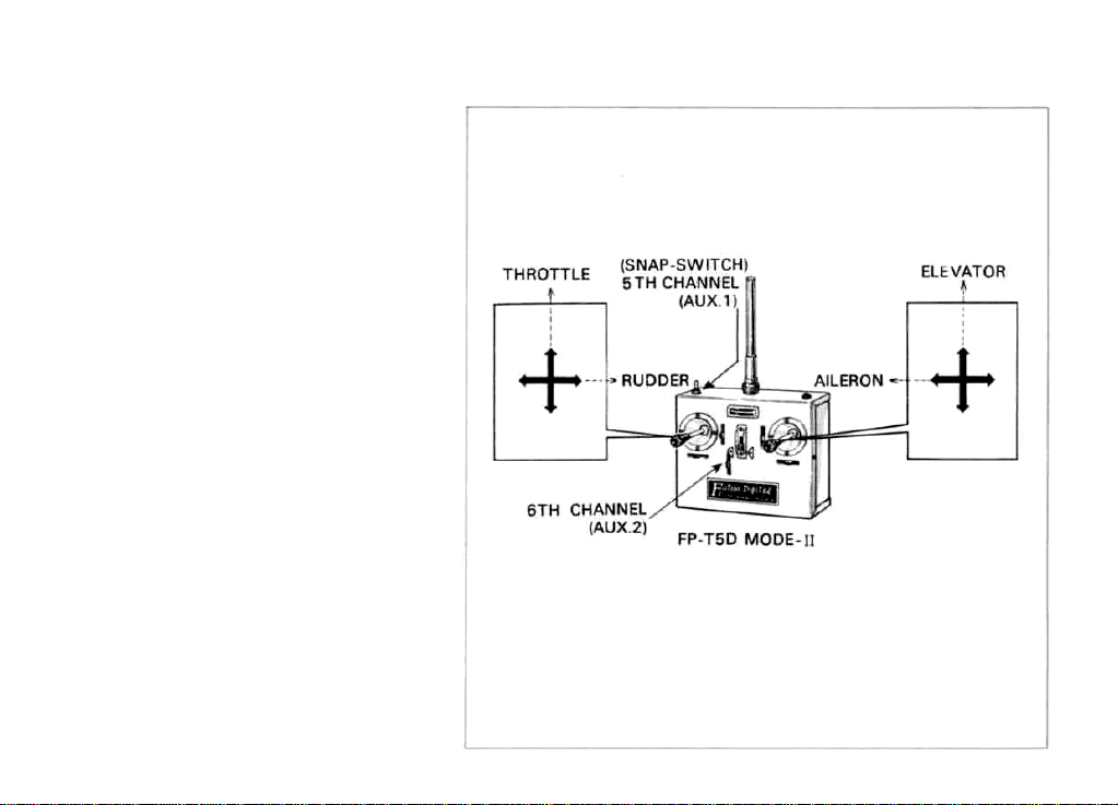
The front panel controls on the Transmitters are shown in the Diagram below and it is suggested that the manipulation of these controls be well mastered.
4
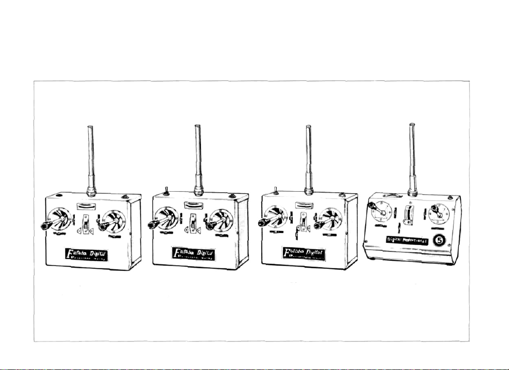
FP-T4D
(for FP-4DN)
4-CHANNEL
FP-T5D
(for FP-5DN)
5-CHANNEL
FP-T6D
(for FP-6DN)
6-CHANNEL
FP-T5
(for
FP-5)
5-CHANNEL
Page 6

1. FP-4DN, FP-5DN, FP-6DN and FP-5 Transmitters are equipped with a built-in transformer-type charger for
maximum safety and provided
2. With the antenna firmly in place, turn the switch on and the Meter needle will point to 10 or more on the Dial.
This is an indication that a Radio signal is being radiated. If the meter needle does not move, check for a possible bad connection in the power supply unit.
3. When the meter needle points below 10, this indicates that the battery is not sufficiently charged.
4. Please be aware that whenever the meter needle falls below 10, the area covered by the signal is diminished.
5.
Along
side and
controls. You can adjust (Trim) these levers for fine adjustments for all four (4) operations such as throttle,
ailerons, elevators and rudder.
below
each
with
control
8/450
sticks are
mAH
Nickel
Cadmium
two
(2) small Black levers. These allow
Batteries for dependable operations.
"trim"
of all
four
main
6. FREQUENCIES - Available in MHz.
(Available Futaba pair crystal Tx/Rx)
27 MHz Areas
26.995 (Brown)
27.045
27.095 (Orange)
27.145 (Yellow)
27.195 (Green)
Remarks: Mark * = Model Aircraft use only.
Mark (**) = Factory tuned convertion of crystal is required.
(Red)
72
MHz Areas.
* 72.080 (Brown/White)
72.160 (Blue/White)
* 72.240 (Red/White)
72.320 (Violet/White)
* 72.400 (Orange/White)
72.960 (Yellow/White) (**)
* 75.640 (Green/White) (**)
5
Page 7

HANDLING THE RECEIVER AND SERVOS
1 . The FP-R6D receiver incorporates an 8
Bit integrated circuit and is made into
6-channel operation. The same integrated circuit is also used for Four (4)
and Five (5) channel operation.
2. The Block connector sockets that connects the different Servos are an integral part of the receiver.
3. The Block Connector sockets are polarized and each position is designated
on the receiver case. Therefore check
carefully before connecting the Servos.
Particularly care must be taken since
the power supply relay connector is
Red and the Aileron relay connector
is BLACK.
4. Since each Servo is built to the same
specifications, any Servo can be used
for any purpose.
5. There is a FP-S5L (Reversible Servo
Red Label) included in each set. This
Servo is convenient for throttle control
on shoulder wing models.
6
Page 8

6. Connectors are made as shown in the above diagram. Please make certain that each connector is fully plugged
in and that the Aileron section etc., and the power supply switch harness is correctly identified.
7. After making certain that the connections are correct according to the above diagram, turn on the transmitter
switch and then put the receiver switch to ON position. At this point each Servo will stop at the Neutral
position.
8. Move each stick and Trim lever and check to see if the specific Servo is actuated correctly.
9. When each section is tested for movement, please make certain that both the Transmitting and Receiving
antennas are fully extended. If the Transmitting antenna is shortened and the Transmitter switch is left ON
for more than 5 minutes, the transistors in the Transmitter will be damaged.
10.
If the system does not operate after completely assembling the batteries, switch harness and Servos for the
receiver and the Transmitter, the problem may be due to damage during shipment. Do not attempt to open
any of the units, but return them for exchange.
7
Page 9

NI-CAD BATTERIES AND RE-CHARGING
FP-4DN, FP-5DN, FP-6DN and FP-5 Transmitters are equipped with eight (8) pen-light type Ni-Cad batteries.
For the Receiver & Servos, Four (4) Ni-Cad batteries are provided in the set.
Prior to each usage Ni-Cad batteries should be charged for 12 to 15 hours. If they have not been in use for some
time, the batteries should be charged for about 20 hours before use. There is no harm if the charging time is
slightly exceeded.
When Ni-Cad batteries are completely charged, you can ordinarily expect about 100 minutes of use during a given
day, about 10 control sessions of 10 minutes each.
Normally Ni-Cad batteries will hold an average voltage however, after this given time period of use, the voltage
will drop suddenly so it is recommended that following 7 or 8 control sessions of use, a voltage check be made
without fail.
For charging the Ni-Cad batteries, connections should be made as shown in the Diagram.
For charging either TRANSMITTER only or RECEIVER, both 'A' & 'B' plugs must be plugged into Transmitter bottom as
shown in the above diagram.
8
Page 10

TO CHARGE TRANSMITTER BATTERIES
1. One end of the charging cord should be plugged into "A"
into the wall socket of the household electric power outlet (AC 115V).
TO CHARGE THE RECEIVER
1. Use receiver charging harness (red 3 pin connector and Plug) as shown in diagram.
Red 3 pin connector should be plugged into battery unit and the other end with plug into Transmitter Marked
"B".
at the bottom of the Transmitter and the other end
PRECAUTIONS FOR OPERATIONAL
TEST AND INSTALLATION
1. After making certain that the Receiver & Servos are hooked up according to the diagram and batteries checked
extend the Transmitter antenna to its shortest length and with the receiver antenna in extended condition, if the
controls functions properly at the distance of 50 to 100 feet the system is operating normally. However it should
be cautioned that this should not continue any longer than Five (5) minutes, otherwise it might damage some
components. Never test the system without attaching the antenna to the Transmitter as this will also have and
undesirable effect on the instrument.
2. During the installation wrap the receiver well with sponge rubber so that it will not touch other mechanisms
or the aircraft itself. Also be careful to prevent engine vibrations from affecting the receiver. As for the Boat
use, in addition, it might be a good practice to cover each unit with vinyl bag and tied securely at each cord
to prevent water from entering.
9
Page 11

3. When installing the Servo, the use of
the Servo tray is very convenient. This
is done according to the diagram.
Please make sure each connector is
plugged in completely.
Always re-check the installation of the
Servo Horns and Rods to make sure
that their motion matches the move-
ment of the Transmitter control stick.
Use the reversible Servo (FP-S5L) for
Throttle control on shoulder wing
models or for actuating the rudder
and nose gear, however this Servo
can not be used for Aileron.
10
Page 12

4. After setting the push rods on each Servo, using transmitter, actuate each Servo fully from left to right making
sure the rod will not hang-up on any position, otherwise the excessive current flow thru Servo will damage
the unit.
5. Noise (interference) signals should be avoided. For example, if two metal parts are in intermittent contact with
each other due to engine vibrations, noise signals are generated. When these signals enter the receiver, unexpected movements of the Servos can result. Therefore one of the metal surfaces touching each other should
be covered with an insulating material.
6. When the installation is complete, at least once, by all means, visit a nearby radio control expert or the dealer where the equipment was purchased and be advised on proper handling techniques and other items which
require attention. It is necessary while receiving this correct instruction also, to have the installation completely
checked.
Let's enjoy Radio control by taking the advice of experts and observing the rules of Safety.
11
Page 13

GUARANTEE
Your NEW FUTABA Digital Proportional R/C system is guaranteed
for 180 days from date of purchase against all defects in materials or
workmanship. When the attached registration card is returned to us
within Ten days of purchase.
Guarantee is void if this R/C system has been improperly handled,
damaged in a crash or tampered with. The guarantee does not cover
the replacement of Plastic Housings or Electronics components by the
use of improper voltage.
In the event that service is needed, please take your equipment to our
local authorized service station or ship directly to us, you are required
to pay all postage, shipping and insurance charges.
12
This will apply only to continental U.S.A. including Hawaii and Alaska.
Page 14

OUT OF WARRANTY FACTORY REPAIR SERVICE
To insure prompt service, please follow the instructions listed below.
1. Charge batteries for at least 18 hours prior to shipment.
2. Return only the system, separate from your installation. Remove servos from mounts, remove foam
padding from receiver.
3.
Plugs
or other modifications
factory standards at your expense.
4. Carefully pack all components individually with sufficient packing material to prevent shipping damage.
5. Include a brief but thorough explanation of all problems and service required and tape to back of
transmitter. Label servos as to their function.
6. Be sure to include your full address and zip inside the box as well as outside.
7. Include a packing list of all items being returned and double check to make sure all items are.
8. If you return damaged equipment to FUTABA for factory service FUTABA will estimate the cost
of repair and notify you, upon receipt of your payment your equipment will be repaired and return
to
you.
This will apply only to continental U.S.A. including Hawaii and Alaska.
which
interfere
with
factory testing procedures
will
be
returned
to
13
Page 15

 Loading...