

Page 1
Futaba
DIGITAL PROPORTIONAL
RADIO CONTROL
Page 2

Thank you for purchasing a Futaba digital proportional
radio control set.
Please read this manual thoroughly before using your
new
set.
CONTENTS
FEATURES
CONTENTS
TRANSMITTER
NEUTRAL
CONVERSION
OPENING THE TRANSMITTER REAR COVER
AND
CONVERTING TRANSMITTER TO
NiCd SYSTEM
SERVO REVERSING
RECEIVER FP-R3F & SERVO
RECEIVER, SERVO, & SWITCH HARNESS.
THROTTLE->RUDDER
MIXING
RUDDER
FPS24&
....................... 1
AND
LEVER.
LOADING
ADJUSTMENT.
DUAL
S27
EXPLODED
RATINGS
FP
T3EG
TO SELF-NEUTRAL
THE
..................... 4
RATE
............. 2
.............. 3
.................. 3
BATTERIES
................. 5
............
............... 7
................ 8
VIEWS.
........ 3
......... 4
5
... 6
......... 9
IMPORTANT: _______________________________________________________
AN FCC CLASS C LICENSE IS REQUIRED TO OPERATE THIS SYSTEM. WRITE TO THE
FEDERAL COMMUNICATIONS COMMISSION AS LISTED BELOW FOR AN APPLICATION FORM #505.
FEDERAL COMMUNICATIONS COMMISSION
P.O.
BOX
1010
Gettysburg, PA 17325
*AII prices and specifications subject change without notice.
Page 3

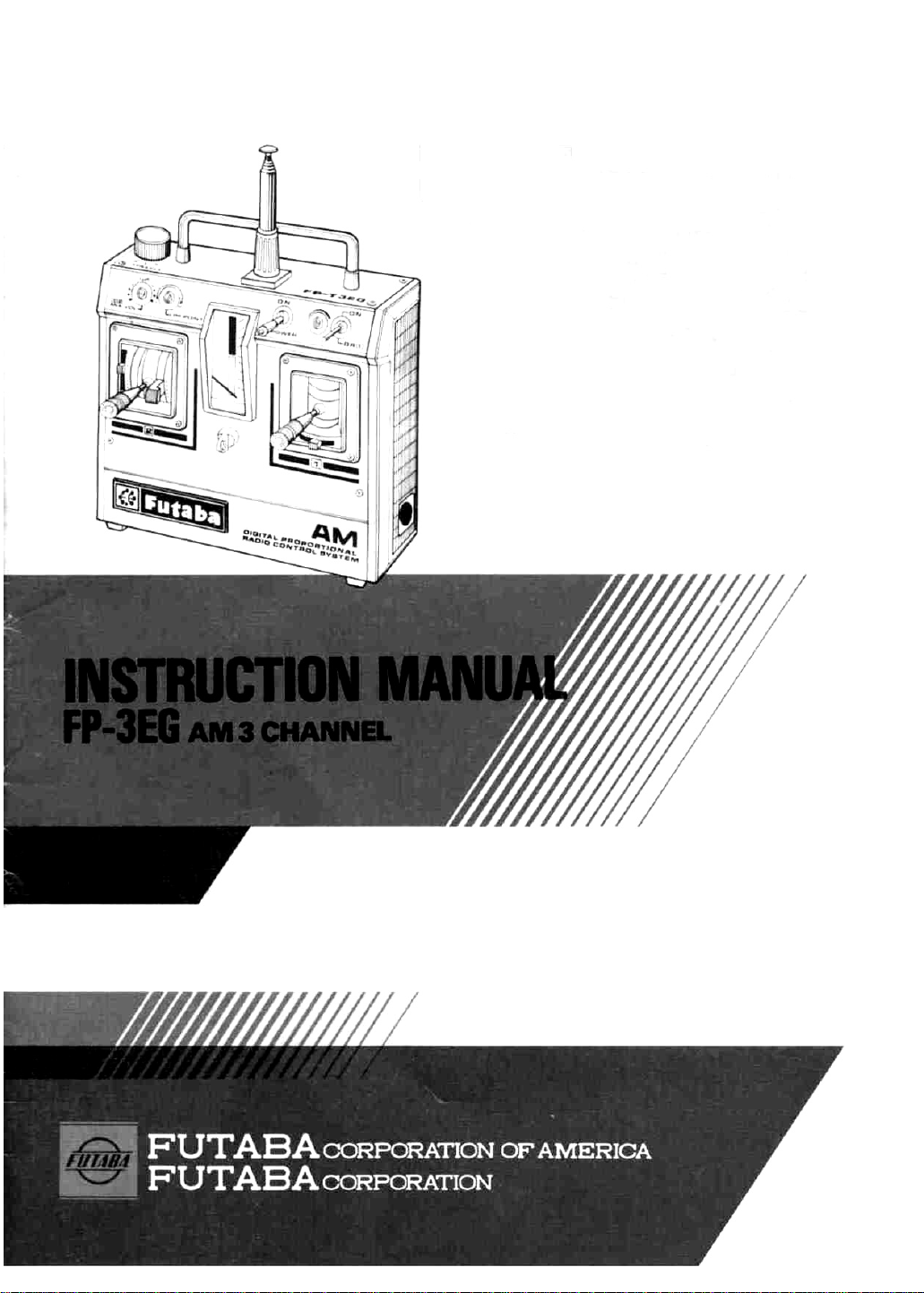
•FEATURES
The FP-3EG is a high quality 3 channel, expanded digital proportional radio control set.
The receiver and servo power is a four-battery; 4.8V (Ni-Cad)/6.0V (Dry-Cell). The
transmitter power supply is 9.6V (Ni-Cad)/10.5V (Dry-Cell). 3FG with S24 servos
only comes with Ni-cads for both
highest in its class.
TX
and RX. Speed and torque of our servo are the
Transmitter FP-T3EG
•Rudder dual rate (dual-rate on, dual-rate
off). The desired rudder angle can be selected when dual-rate on.
•Servo reversing switch
throttle channel.
•Throttle and rudder mixing is adjustable
up to the limit point.
•Three channel transmitter. Third channel
has a click knob and can be conveniently
used as a subchannel.
•Throttle
but can be instantly changed to a ratchet
type.
• Semi-open gimbal sticks provide maximum
feel.
• Neck band provided as standard. Comfortable operation is possible by hooking
the band around your neck.
•Seven pen-cell battery power supply can
also be changed to Ni-Cad battery (NT-8C).
• Beautiful exterior based on human engine-
ering. Easy-to-use design.
lever
has a neutral
at rudder and
shift
device,
Servo FP-S24
•Highest output torque (4.5kg-cm/62.7oz-in.
or greater) of any servo in its class.
•Output
nd
• Large 20m/m diameter coreless motor fea-
• Indirect drive system extends the life
• Watertight/dustproof.
gear
is
supported
bottom by ball bearings for excellent
neutral characteristics, long life,
smooth operation.
tures high torque near neutral and exact
tracking of even minute rudder movements.
the potentiometer substantially.
Besides the FP-S24, FP-S27, watertight
servo is available with this system.
at
the
top
and
and
of
1
Receiver FP-R3F
•Miniature type, light, weight, rugged construction.
•Crystal is replaceable from the outside.
•3P mini-connectors are compatible with
existing sets.
•3 channel specifications.
•Newly developed receiver use Futaba Custom I/C, BA633. This I/C is extremely
stable against power supply voltage fluctuations.
•Adjacent frequency interference is minimized by the use of an RF amplifier circuit
and ceramic filter.
Page 4

•CONTENTS AND RATINGS
Set name
Transmitter
Receiver
Servo
Switch
NiCd battery/Batt holder
Others
Transmitter FP-T3EG
Operating system
Transmitting frequency
2
Modulation system
Power supply
Current drain
: 2 sticks, 1 knob, 3
channels
: 27MHz Bands
72MHz Bands
:
AM
: 10.5V, 7 pen-cell
batteries or
9.6V NiCd (NT-80
: 130mA
Receiver FP-R3F
Receiving frequency
Intermediate frequency
Receiving range
Power requirement
Current drain
Dimensions
Weight
: 27MHz Band
72MHz Band
: 455kHz
: 550 yards (500m)
on the ground
1100 yards (1000m)
in the
: 4.8V Ni-Cad
(NR-4C) or
6.0V AA pen-cell
dry battery x 4
:
6V 10mA
: 1.6x7.5x2.3 in.
(40.2x19.0x58.5mm)
:
1.6
oz
FP-T3EG x 1 Pen-cell Dry Battery Type or NiCd Battery Type.
FP-R3F x 1
FP-S24 x 2 or FP-S20x2 or S21Sx2 or S26x2 or S27x2
SWH-1
NR-4C/AA0312
Frequency flag, neck band, horn, servo tray, battery charger
(w/S24 only)
Servo FP-S24
Control system
Operating angle
Power supply
Current drain
Output torque
Dimensions
Weight
air
battery
(46g)
FP-3EG
: + pulse width
trol
1310 us.N
:
One
side 45°
more (including
trim)
: 4.8-6.0V (shared
with receiver)
:
8mA
at 6.0V
(stopped)
: S24 62.6 oz/in.
(4.5 kg/cm)
S2747.3oz/in.
(3.4 kg/cm)
: S24
1.8x0.9x1.5in.
(45.4x23x38mm)
S27 1.8x0.9x1.7in.
(45.5x23x43.5mm)
:
S24
2.1
S27 1.9oz
oz
con-
or
(59g)
(53g)
Page 5

•TRANSMITTER
The below figure gives the name of each part
of the transmitter.
Memorize the position and operation of each
switch and control.
3 3rd channel
7 Limit point
trimmer
6 Mixing trimmer
9 Throttle trim
2 Throttle
10 Neutral shift
lever
13 Antenna
12
Handle
11 Power switch
5 Rudder dual
rate trimmer
4 Rudder dual
rate switch
8 Rudder trim
14 Hook
3
1 Rudder
Description of Fig. 1
1 Rudder. ..... .Rudder operation
2 Throttle ..... .Throttle or elevator opera-
3 3rd channel . . . .
4 Rudder dual rate
switch
......
5 Rudder dual rate
trimmer ..... .Adjusts the amount when
6 Mixing trimmer . .Throttle — rudder mixing
tion
Needle control, etc.
.Rudder
dual-rate
switch
the rudder dual rate switch
is set to ON. (Amount is
continuously adjustable
from 40% to 100% at dualrate on.)
amount trimmer
on/off
7 Limit point
trimmer .....
8 Rudder trim . . .
9 Throttle trim . .
10 Neutral shift
lever
......
11
Power switc h
2 Handle
1
3 Antenna
14 Hook
......
Fig.1
.Changes the mixing amount
limit at throttle -< rudder
mixing.
.Rudder fine adjustment.
.Throttle fine adjustment.
.Changes the neutral posi-
tion of the throttle control
stick in 5 steps.
.The accessory neck band
hooks to this hook.
Neutral Lever Operation Conversion from Self-Neutral System to
The stick lever neutral
position can be adjusted in 5 steps by moving
the lever as shown in
the figure.
Fig.
2
ratchet System
Remove the
spring and
swing arm.
Install the slide plate.
Twist with needle
nose pliers, etc.
Fig.
3
Page 6

•OPENING THE TRANSMITTER REAR
COVER AND LOADING THE PENLIGHT
BATTERIES
4
• Remove the rear cover of the transmitter as
shown in Fig. 4 and load the 7 pen-cell batteries in the correct polarity.
• Extend the antenna fully and set the POWER
switch to ON. The meter pointer should deflect to the green zone. If the meter pointer
does not move, or moves very little, check for
poor battery contact, incorrect battery polarity, or faulty batteries.
• When the meter pointer enters the red zone,
the range of the radio waves will become
short. Change the batteries when the meter
pointer drops to the boundary between the
red and green zones.
• Use the trim lever to fine adjust each rudder.
This lever can also be used to adjust the neutral position and the flight posture after the
mechanism has been mounted. However, after
test flight, all adjustments should be made
with the rod adjusters, etc. and the lever
handle should be left in the neutral position
as much as possible.
• The throttle stick neutral position can be
selected in 5 steps by moving the neutral lever
as shown in Fig. 2.
Adjust the neutral position to match the application.
•With the NiCd system FP-T3EG, recharge the
battery as shown in Fig. 6(B).
The NT-8C is already installed.
• To change the elevator stick from a selfneutral type to a ratchet type, install the slide
plate and remove the spring and stick arm as
shown in Fig. 3.
Converting the transmitter
to a NiCd system
Remove the charging
socket blind cover.
Pay careful attention to the
of the 7 pen-cell batteries.
Wrap rubber bands around the
batteries to hold them in place.
Fig.
6(B)
polarity
Charging the
FP-T3EG NiCd.
Insert the charger
and TX plug into
the charging jack
on the side of the
transmitter.
The charging LED
at the TX lights to
indicate that the
battery is being
charged.
yy
Fig. 6 (A)
•Use the NT-8C transmitter
NiCd battery sold separately
Page 7

•REVERSING THE SERVO
After connecting the linkage, check each rudder.
If the direction of the rudder and the stick operating
Fig.
7
•RECEIVER FP-R3F and SERVO
FP-S24 5
•Plug the charge (FBC-1 or FBC-2A optional)
into a 110V outlet and connect the 3P connector of the charger to the receiver/servo
NR-4C NiCd battery pack as shown in Fig. 8.
The LED on the charger will light to indicate
that the NiCd battery is charging.
•The
NiCd battery
12 times at 10 minutes/time.
• Always recharge the battery before use.
• The charging time is about12~15 hours
pack
can
be
direction are opposite, switch the reversing switch.
15 Rudder reverse switch
16 Throttle reverse switch
15 Rudder reverse switch (Reverses the direction
of operation of the rudder servo.)
16
used
Throttle
about
reverse
switch
of operation of the throttle servo.)
(Reverses
the
direction,
•With the battery system, insert the four
dry-cell batteries, being sure that the polar-
ity is correct, then firmly tighten the coin
screw.
• Connect the servo and switch as shown
Fig. 9. Then extend the transmitter
ceiver antennas fully.
•Set the transmitter POWER switch
then set the receiver POWER switch to ON.
The servo will stop near the neutral
tion.
Operate each stick of the transmitter and
check that the corresponding servo faithfully follows the movement of the stick.
•Set
the pushrod at
each
servo
horn,
and
to ON,
posi-
then
re-
check that the direction of servo matches
the direction of transmitter stick.
•Operate each servo horn over its entire
in
operating range and check if the pushrod is
too tight or too loose.
Applying unreasonable force to the servo
horn will adversely affect the servo and
quickly drain the batteries.
Always make the operating width of each
rudder somewhat larger than the full
stroke (including trim) of the servo horn.
Adjust the servo horns so that they operate smoothly even when the trim lever and
stick lever are operated simultaneously in
the same direction.
Page 8

Fig.
9
• Be alert for noise.
6
If engine vibration causes metal parts to
touch, noise will be produced and the receiver and servos may operate incorrectly.
We recommend the use of noiseless parts.
• When installing the switch, cut a rectangular hole somewhat larger than full stroke
of the switch and install the switch so that
it moves smoothly from ON to OFF. When
the switch is mounted inside the fuselage
and is turned ON-OFF with wire, install
the switch mount in the same manner.
Install the switch where it will not come
into direct contact with the engine oil,
dust, etc.
• Even though the receiver antenna is long,
do not cut or bundle it.
• Install the servo firmly. Refer to Pig. 10 at
the right.
•A spare servo horn is supplied. Use it as
needed. Do not forget to install the tooth
washer when changing the horn.
•Wrap the receiver in sponge rubber. Place
the receiver in a plastic bag and wrap a
rubber band around the open end of the
bag to waterproof and dustproof the re-
ceiver.
Do
the
same
with
the
receiver bat-
tery.
• Also use the rubber bands wrapped around
the receiver to hold the servo and switch
leads.
•After mounting is complete, recheck each
part, then make the transmitter antenna as
short as possible, extend the receiver antenna fully, and operate the set from a dis-
tance of 22 to 33 yards (20 to 30m) for
range check. The movement of each servo
should follow the operation of each stick
of the transmitter.
Page 9

•THROTTLE -> RUDDER MIXING
ADJUSTMENT
The rudder neutral position at engine SLOW
and engine HIGH depends on the engine
torque. When adjusted for straight ahead
when a common 2-cycle glow plug engine is
at HIGH, the boat will slowly swerve to the
left at SLOW and if adjusted for straight
ahead when the engine is at SLOW, the boat.
will slowly swerve to the right at HIGH. Mix-
ing from throttle to rudder, the biggest
feature of the Model FP-3EG, completely
eliminates this tendency.
The following description is for a common 2-
cycle glow plug engine that rotates counter-
clockwise. Reverse the description for a gasoline
engine, electric motor, etc. that rotates clockwise.
This mixing is adjusted with the mixing
trimmer and limit point trimmer at the left
front of the transmitter.
Mixing trimmer 6 adjusts the amount and
direction of movement of the rudder servo
when the throttle stick is moved up and
down. The mixing amount is zero at the
center position.
Limit point trimmer 7 changes the point at
which the operating line of the mixing
amount to the rudder servo curves when the
throttle stick is moved from LOW to HIGH.
1 When the throttle stick is set to HIGH, a
boat moving straight at engine control
SLOW will swerve to the right. On the
other hand, a boat moving straight ahead
at throttle HIGH will swerve to the left
when the throttle stick is set to SLOW.
That is, the rudder servo should be turned
to the right when the throttle stick is set
to SLOW.
2 Turn the mixing trimmer with a screw-
driver so that the rudder turns slightly to
the right when the throttle stick is moved
from HIGH to SLOW.
You should now have a good understanding
of throttle to rudder mixing.
Throttle -> rudder mixing will be called
"MIX" hereafter.
3
• Run the boat without MIX (MIX trimmer
at center) and check the rudder neutral,
play, and engine SLOW and HIGH.
• Limit point
Turn the trimmer about
2/3 clockwise.
(In the L to H direction.)
•Under
this
state,
turn the MIX trimmer
about halfway in the R (right) direction
and check the rudder movement (rudder
servo) while moving the throttle stick up
and down. The rudder should move a little
to the right at SLOW and a little to the left
at HIGH.
•Set
the
MIX
trimmer
to
zero (center) at
throttle stick HIGH. The rudder servo
should not move because the mixing
amount is zero at throttle HIGH as shown
in
Fig. 11.
4 After all preparations are complete, make
adjustments while actually running.
A Adjust the rudder trimmer so that the
boat travels straight ahead at throttle
HIGH.
B Set the throttle stick to SLOW. If the
boat
swerves
to
the right
at
this
time,
the
MIX amount is excessive. Reduce the
MIX amount by turning the MIX trimmer
toward the center. If the boat slowly
swerves to the left, the MIX amount is insufficient. Increase the MIX amount by
turning the MIX trimmer in the R direction.
C This completes MIX adjustment at throt-
tle SLOW and HIGH. However, adjustment near medium SLOW is still necessary. To adjust near medium SLOW,
proceed as follows:
7
Page 10

(a) If the boat slowly swerves to the right
when the throttle stick is set to medium SLOW, the POINT is too high.
Adjust it by turning the limit point
trimmer counterclockwise. Then readjust item B above.
(b) If the boat slowly swerves
the POINT is too low. Adjust by turning the limit point trimmer clockwise.
Then readjust the MIX trimmer as
described in item
RUDDER DUAL RATE (DUAL-RATE ON,
DUAL-RATE OFF)
•Rudder dual rate switch
Dual-rate (servo stroke becomes narrow) is
effected when this switch is set to ON.
Dual-rate is off when the switch is set to
OFF. OFF is the normal state.
• Rudder dual rate trimmer
This trimmer adjusts the full stroke of the
servo when the rudder dual rate switch is
set to ON. Adjust it to match the course
and technique. The rudder dual rate
amount is continuously variable from 40%
to
100%.
•The
Futaba
combined with any Futaba transmitter and
receiver. Use it to match the application.
(However, except the Futaba J Module
Series.)
•After mounting and checking are complete,
take your model to the store where you
purchased the digital proportional set, or
to an experienced radio control enthusiast,
and ask them to tell you how to install
your radio control set correctly and to inspect your set-up carefully.
Mini
(B).
3-pin
wire servo can be
to the left,
Futaba
Digital Proportional Frequencies
Band
Band
Band
Band
Band
The frequency of Futaba digital pro-
portional sets can be changed among
bands (1)~(5) on the 27MHz band
only.
However, a 27MHz band set cannot be
changed to 72MHz band, and vice
versa.
Therefore, always attach the correct
frequency flag to the end of the
transmitter antenna. Each frequency
band has its own designated color, as
stated above.. The frequency flag is in-
tended for identification purposes.
Also change the frequency flag when
changing the crystal.
Futaba paired crystals are precisely
matched. Always use a Futaba crystal
set (transmitter, receiver) when chang-
ing the frequency.
It is illegal to change crystals of transmitter on the 72-76 MHz bands in the
U.S.A.
(1)
(2)
(3)
(4)
(5)
•
*
*
•
*
26.995MHz
27.045MHz
27.095MHz
27.145MHz
27.195MHz
72.080MHz
72.160MHz
72.240MHz
72.320MHz
72.400MHz
72.960MHz
75.640MHz
Aircraft use only.
Brown
Red
Orange
Yellow
Green
Brown/White
Blue/White
Red/White
Violet/White
Orange/White
Yellow/White
Green/White
FACTORY REPAIR SERVICE
To insure prompt service, please follow the instructions given below.
1. Charge the batteries for at least 18 hours prior to shipment.
2. Return the system only.
padding from the receiver.
3. Plugs or other modifications which interfere with factory test procedures will be returned to factory standard at
your expense.
4. Carefully pack all components individually, using sufficient packing material to prevent damage during shipment.
5. Include a brief
mitter. Place a label describing the function of the servo on each servo.
6. Be sure to include your full address and tel. No., zip code in»ide the box as well as on the outside.
7. Include a packing list of all items being returned, and double check to make sure that all items are packed.
8. Upon receipt of your equipment at the Futaba factory, an estimate of the cost of repair (over $25.00 only) will be
sent to you. Your equipment will then be repaired and returned to you upon receipt of payment or C.O.D. (cash).
This factory repair service applies only to the continental U.S.A., Hawaii, and Alaska.
but thorough explanation of all problems and service required and tape it to the back of the trans-
Not your complete installation. Remove the servos from their mounts and remove the foam
Page 11

FP-S24
9
Page 12

 Loading...