

Page 1
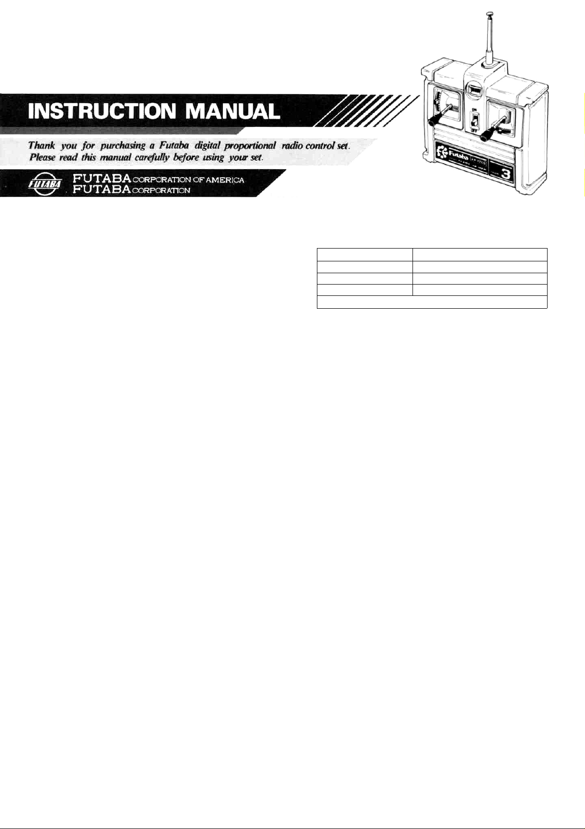
Futaba
DIGITAL PROPORTIONAL
RADIO CONTROL
FP-2GS
D60431
SPECIAL FEATURES:
TRANSMITTER FP-T2GS
• Contemporary
superior control.
• 500mW output.
• Battery level
voltage at a glance.
• Built-in antenna.
RECEIVER FP-R102GF
•BEC (Battery Eliminator Circuitry) system allows sharing
of the running Nicd battery and eliminates the need
regulator and diode.
•High performance 2 channel receiver with ASP system
when used with the proper transmitter.
•Crystal
socket
ture pins. Reliability is increased and the crystal can be
changed from the outside.
SERVO FP-S128
SMALL, RUGGED. HIGH NEUTRAL SERVO
•Skew type armature motor.
Movement of the trimmer by even one notch is tracked by
a skew type motor which displays a performance near that
of a
coreless motor.
•New indirect drive potentiometer improves vibration and
shock resistance and neutral accuracy.
•Futaba low-power custom 1C provides extremely high
torque, narrow dead band, and superior tracking.
•Fiberglass reinforced PBT (polybutylene terephthalate)
injection
invulnerable to glow fuel.
•Strong
smooth operation, positive neutral, and very little backlash.
•Fiberglass reinforced epoxy resin PC board with thru-the-
hole plating improves servo amp vibration and shock resistance.
•Three pin connector eliminates faulty contact and improves
reliability against vibration and shock. Housing has a
reverse insertion prevention mechanism.
•Special grommet simplifies
an excellent cushioning effect.
•Six special adjustable splined horns.
•High 48.7 oz.in
use
molded
polyacetal
in almost any model.
styling with smooth operating gimbals for
meter indicates the state of the battery
for a
uses a new
servo
resin
type
of highly reliable subminia-
case
is
mechanically strong and
ultra-precision
servo
gear
features
mounting of the servo and has
(3.5kg-cm) maximum output torque allows
SET CONTENTS AND RATINGS
(Specifications are subject to change without prior notice.)
Model number
Transmitter
Receiver
Servo
Switch, battery holder, etc.
FP-2GS
FP-T2GSx1
FP-R102GFx1
FP.S128.x2
TRANSMITTER FP-T2GS.
Operating method 2 stick system
Transmitting frequency 27MHz band, 72MHz band
Modulation system AM (amplitude modulation)
Power requirement
12V,
round penlight battery x 8
Receiver FP-R102GF
Receiving frequency
Intermediate frequency
Selectivity
Receiving range
Power supply
Current drain
Dimensions
Weight
27MHz band, bands 1 to 6
72,75MHz
455kHz
3kHz/-3dB
550 yards (500m) on the ground
when used with FP-T2GS (At the
best radio wave condition of environment)
4.8V
to
8.4V
7.2V/13mA,4.8V/33mA
1.46x
2.19 x 0.75
(37 x 55.5 x 19mm)
1.34
oz
(38g)
in
SERVO FP-S128
Control system
Operating angle
Power requirement
Current drain (IDLE)
Output torque
Operating speed
Dimensions
Weight
+pulse width control
One side 45° or more
4.8V-6V
6.0V, 8mA (at idle)
48.7 oz.in. (3.5 kg-cm)
0.24 sec/60°
1.6x0.8x 1.6 in.
(40.5 x 20 x 40.5mm)
1.92oz. (53g)
HANDLING THE TRANSMITTER
•The name of each part of the transmitter is given in the figure.
Familiarize yourself with their operation.
•Remove the battery cover on the rear of the transmitter as
illustrated in the figure, and insert 8 round penlight batteries,
paying careful attention to their polarity.
•Extend the antenna fully, and set the power switch to the
ON position. The pointer of the level meter should deflect to
the green zone. If it fails to deflect, or deflects slowly, the
polarity of the batteries is incorrect, or the batteries are
faulty.
•Since the range of the radio waves will become short when
the pointer of the level meter deflects to the red zone, replace the batteries when the pointer only deflects to the
boundary between the green and red zones.
Page 2
•The
trim
lever
is
used
to fine
adjust
each
channel.
Use
it for
neutral adjustment and to correct the flying posture after
the mechanism has been installed. After test flight, operate
with the trim lever in the neutral position, as far as possible,
by correcting with the rod adjuster, etc.
•Since the elevator stick employs a self-neutral system, install
the sliding plate as shown in the figure when changing it to a
ratchet system. Then remove the strong spring attached to
the hook and replace it with the spring supplied as an accessory.
Antenna
Level meter
(Engine control
trim)
Elevator trim
Elevator stick
(engine control
stick)
Power switch
Rudder
trim
Rudder stick
Fig.1
•When the transmitter is used with a tank, the direction of the
stick can be changed 90 degrees by removing the four rudder
stick mounting screws.
•To change the crystals, loosen the rear cover mounting screws,
remove the rear cover, and then replace the crystal. The
crystal is located at the left side of the printed wiring board.
The transmitter crystal is marked (T) and the receiver crystal
is marked (R). CAUTION: Frequency change has to be done
under the supervision of FCC licensed personnel.
The batteries can be
easily loaded by
Rear cover mounting screws
Fig.
Slide in the direction
of the arrow while
pushing here.
inserting them
a time from the back.
2
four at
Modification from self-neutral
system to ratchet system.
Install sliding plate
Replace with
weak spring
Fig.
3
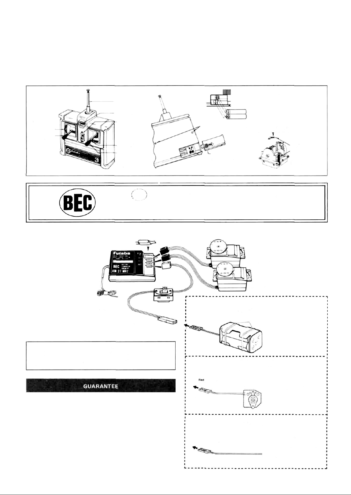
The BEC mark is displayed on the front of the receiver of BEC (Battery
Eliminator Circuitry) system sets with a receiver with shared power supply
regulator.
RECEIVER FP-R102GF AND SERVO FP-S128
Receiver crystal
Fig.
4
Receiver FP-R102GF
Antenna mire
Connect the servo and switch as
shown in the figure and extend
the transmitter and receiver antenna fully.
Red common 2P
connector (male pins)
The Futaba BEC (Battery Eliminator Circuitry) system and BEC
& ASP (Adjustable Safety Position) system can also use a common power supply with the conventional four penlight batteries
system (separate power supply).
Your NEW FUTABA Digital Proportional R/C system is guaranteed against defects in workmanship and material for 180 days
from the date of purchase when the attached registration card is
returned to us within ten days of purchase.
This Guarantee is null and void if the R/C system has been im-
properly handled, damaged in a crash, or tampered with and
does not cover the replacement of plastic housings or electronic
components damaged due to the use of improper voltages.
When service is required, please take your equipment to your
local authorized service station or ship it directly to us. All
postage, shipping, and insurance charges must be paid by the
user.
ON
Switch
OFF
Red common 2P
connector
(Female pins)
Red common 2P
connector
(Female pins)
Red common 2P
connector
(Female pins)
Steering servo
Throttle servo
Connection to this connector
(1)When chassis power supply of
engine or motor car is separate
Wrapped with
rubber band.
(75MHz-OPTIONAL)
(2) When motor car uses a speci-
al 8EC system chassis (common power supply specifi-
cations)
Controller
(3) When motor car uses an ordi-
nary common power supply
chassis
Connect to the red common
2P connector of the control-
ler.
Buy the red common 2P
connector from the kit
manufacturer and connect to
the controller.
Pin 1: Minus
Pin 2: Plus
Page 3

•A common power supply regulator and diode may also be supplied with the speed controller, depending on the vehicle
kit. Since they cause a voltage drop, always remove them.
TO BUYERS OF THE FP-2GS (FP-R102GF)
When using a Futaba motor control amp instead of
the speed controller supplied with the vehicle, turn
off the ASP (Adjustable Safety Position) system as
shown in the figure.
Insert the ASP release co-
nnector packed "with
set at this 2P connector
(male pins) on the
wiring board.
printed
R102GF ASP
release
connector
the
Fig. 5
•Set the transmitter power switch to ON, then set the receiver
power switch to ON. The servos stop near the neutral position.
Operate the transmitter sticks and check if each servo faithfully
follows operation of the sticks.
•Connect the pushrod to each servo horn, then check if the direction of travel of each servo matches the transmitter operation.
•Operate each servo over its full travel and check if the pushrod
binds or is too loose. Applying unreasonable force to the servo
horn will adversely affect the servo and quickly drain the battery.
Be especially careful when using 8.4V.
•Always make the full stroke (including trim) of the servo horns
somewhat larger than the full travel. Adjust the servo horns so
that they move smoothly even when the trim lever and stick are
operated simultaneously in the same direction.
• Be alert for noise.
Always solder a noise killing capacitor to the running motor. If
metal parts touch each other due to vibration, noise will be generated and cause the receiver servos to operate erroneously. We recommend the use of noiseless parts.
• Even though the receiver antenna wire is long, do not cut
bundle it. The range of the radiowaves will be shortened.
Fig.
6
• Install the servos firmly. Install the servo to the servo tray
as shown in the figure. In other cases, install the servo as
described in the model manufacturer's manual.
Fig.
7
• A spare horn is provided. Use it as required.
•Wrap the receiver in sponge rubber and wrap rubber bands around
the sponge rubber. Mount the receiver so it is not exposed to vibration, does not touch the frame, and does not move.
•When the receiver is installed on a board or used where it may be
splashed with mud and water, place it in a plastic bag, etc. and
wrap a rubber band around the open end of the bag to waterproof
and dustproof the receiver. After use, remove the receiver from
the bag to prevent condensation.
• Use the rubber bands wrapped around the receiver to hold the
servo and switch leads.
•After mounting is complete, recheck each part, then check the
transmitting range by making the transmitter antenna as short as
possible and extending the receiver antenna fully and operating
the set from a distance of 20m to 30m. The movement of each
servo should follow the movement of the transmitter sticks.
•The crystal can be changed from the outside of the receiver case.
Always use a Futaba transmitter and receiver crystal pair as the
or
replacement crystals.
REPAIR SERVICE
• When requesting repair of trouble that has occurred suddenly
of from long use, describe the trouble symptoms in as much
detail as possible.
This will facilitate detection of the trouble point and shorten
the repair period greatly.
• Defects caused
corrected free of charge.
• This limited warranty is null and void if the set has been tampered with or disassembled.
Refer to warranty statement for details.
by
faulty
materials
or
workmanship
will
be
WORLD SALES & SERVICE FACILITIES
Australia: FUTABA SALES AUSTRALIA PTY. LTD., Lebanon:
MELBOURNE TEL: 211-4788
Argentine: MODELISMO AE RONAUTICO DEGA SRL. New Zealand:
BUENOS AIRES TEL: 393-2299
Canada: UDISCO LTD., MONTREAL
TEL: 481-8109 Norway:
Chile: HOBBY LANDIA, SANTIAGO
TEL: 743957 Singapore:
Denmark: FUTABA IMPORT DENMARK,
COPENHAGEN TEL: 02-91-0101 South Africa:
England: RIPMAX LIMITED, LONDON
TEL: 01-8048272 Spain:
Finland: NORETRON KY. HELSINKI
TEL: 90-488880 Sweden:
Greece: C. & G. MACR1YIANNIS CO., PIRAEUS
TEL: 021-3604391 • or 021-41 76191 U.S.A.:
Hong Kong: RADAR CO. LTD. TEL: 3-680507
Italy: RADIOSISTEMI SRL, Carrara W.Germany:
TLX: 500494 FORTIMI
FAX: 0039-585-52247
KHAIRALLAH MODELCRAFT, BEIRUT
TEL: 326-681
AMALGAMATED WIRELESS
(AUSTRALIA) N.Z. LTD. WELLINGTON
TEL: 58-979
HARALD LYCHE CO. A/S, Drammen
TEL: (03) 8339 70
SINGAPORE HOBBY SUPPLIES
TEL: 533-0337
REDIPAK (PTY.) LTD.,
JOHANNESBURG TEL: 21-1511
HOBBY & TOY INTERNATIONAL,
VALENCIA TEL: (96) 357 23 93
RADIO CONTROL CENTER,
JONKOPING TEL: 036-145360
FUTABA CORPORATION OF AMERICA,
CALIFORNIA TEL: 213-537-9610
ROBBE MODELLSPORT GMBH,
GREBENHAIIM TEL; 06644-870
Page 4

Futaba
Frequency Channel No. Flag Color
2627MHz
26995
27045
27.095
27 145
27195
27255
72/75MHz
72.030
72.080
72.160*
72.240
72320*
72400
72550
72590
72630
72670
72710
72.750
72790
72830
72.870
72910
72.960*
75.640
Digital
• Aircraft/Car/Boat
-
Bro
Red Flag/Robbon)
Orange
Yellow
Green
Blue
• Aircraft only *'Shared
Bro
12
White/Brown
White/Blue
White/Red
Whi
White/Orange
Orange-Grey
38
Yellow-Black
40
42
Yellow-
44
Yellow-Yellow
46
Yellow-Blue
48
Yell
50
Green-Black
52
Gre
54
Green-Yellow
56
Gre
White/Yellow
White/Green
Proportional
wn
wn.Red(Top Flag/Ribbon Bottom
te/Purple
ow-Grey
en Red
en-Blue
Flag/Ribbon)
Red
Frequencies
75MHz
Car & Boat only
75.430
75.470
75510
75.550
75590
75670
75.710
75750
75790
75830
75870
53MHz -
53
100
53200
53300
53400
53.500
53.600
53.700
53.800
62
64
66
68
70
74
76
78
80
82
84
Aircraft/Car/Boat
—
—
—
—
-
—
—
(FOR U.S.A.)
Blue-Red (Top Flag/Ribbon Bottom
Blue-Yellow
Blue-Blue
Blue-Gray
Purple-Black
Purple-Yellow
Purple-Blue
Purple-Gray
Grey-Black
Grey-Red
Grey-Yellow
FCC Amatuer License Required
Black/Brown
Black/Red
Black/Orange
Black/Yellow
/Green
Black
Black/Blue
Black/Purple generally
Black/Grey
Not
in use
FOR OTHER MARKETS. FOLLOWING
FREQUENCIES ARE AVAILABLE.
FP
2GS
27MHz Band
29MHz Band
35MHz Band
40MHz Band
53/60MHZ Band
72/75MHz Band
AM
FM
0
0
0
0
0
X
X
X
X
X
X
X
The authorized frequencies on each countries
are as follows:
England ......
Sweden.
Scandinavian countries . . .27, 35 and 40MHz
Australia
U.S.A.
......
.................
.........
.27 & 35MHz AM and FM
.27 & 35MHz
27 & 72MHz
AM
AM/FM
and FM
29MHz
(amonly)
•The frequency of Futaba digital proportional sets can be changed among bands (1)
~ (6) on the 27MHz band only.
• However, a 27MHz band set cannot be
changed to 72MHz band, and vice versa.
•Therefore, always attach the correct frequency flag to the end of the transmitter
antenna. Each frequency band has its own
designated
FP-S128
color,
as
stated
in
the
left.
The
No.
1.
2.
3
4.
5.
6.
7.
8.
9.
10.
11.
12.
13.
14.
15.
16.
17.
18
19.
20.
21.
22.
Upper case
Middle case
Bottom case
Metal bearing
Potentiometer
VR drive plate
Motor
Motor pinion
Motor mounting
screw 2x3
1st gear
2nd gear
3rd gear
Final gear
Intermediate shaft
2nd shaft
Servo horn D
Horn mounting screw
2.6 x 8
Printed wiring board
S128...3PBWRB300
Lead wire packing
Case mounting screw
Nameplate
The following splined horns are optional.
HORN A HORN B HORN C HORN D HORN E HORN F
frequency flag is intended for identification purposes.
•Also
change
the
quency is changed.
• Futaba paired crystals are precisely matched.
Always use a Futaba crystal set (transmitter,
receiver) when changing the frequency.
frequency
flag
when
• It is illegal to change crystals of transmitter
on the 72-75MHz bands in the U.S.A.
Part Name
Part No.
FCS-28
S04134
.39995
S02753
S91212
S02461
J60002
FGS-28
S02495
S02494
FSH-6W
FSH-4I
AS 1202
FPC-8M
S90045
J50400
S80700
• SPLINED HORNS
This horn permits shifting of the
servo neutral position at the servo
horn. Setting and shifting the neutral
position
a) Angle divisions
1) The splined horn has 25 segments. The amount of change per
segment is; 360/25=14.4°
2) The minimum adjustable angle is
determined by the number of arms or
number of the holes. For four arms,
the minimum adjustable angle is:
b) Effect
To shift the holes center line to the
right (clockwise) relative to baseline
A, shift arm 2 to the position of arm
1 and set it to the position closet to
baseline A.
(Example] For a four arm horn. the
angular shift per segment is 14.4°.
The shift to the right is 90° - (14.4 x
6» = 3.6°
To shift by the same angle in the
opposite direction, use the opposite
arm number.
For a six arm horn, turn the arm
counterclockwise and set arm 2 to
the position of arm 1. The adjustable
angle is 60° - (14.4 x 4) = 2.4°.
Arm 3 shift 4.8° to the right, arm 6
shifts 2.4° to the left, and arm 4
shifts 7.2° to the right and left.
fre-
Fig.
10
• Furnished swing arm B is convenient when the neutral position of
the swing lever is shifted approximately 1/3 as shown in Fig. 11.
• Open the rear cover of the transmitter, and replace as shown in
Fig.
13
Fig. 11
Fig. 13
Furnished.
 Loading...