

Fusion Oxi-Gen 150-OXi-2P, Oxi-Gen 150-OXi-3P, Oxi-Gen 150-OXi-4P, Oxi-Gen 150-OXi-5P, Oxi-Gen 150-OXi-6P Installation, Operation And Maintenance Manual
Page 1
Installation, Operation and
Maintenance Manual
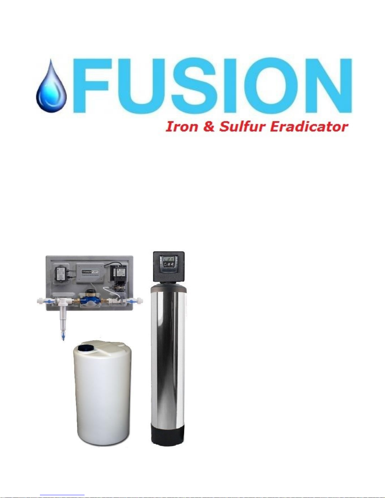
US Water Oxi-Gen Iron, Sulfur
and Manganese Eradication
System
Oxi-Gen 150-OXi-2P
Oxi-Gen 150-OXi-3P
Oxi-Gen 150-OXi-4P
Oxi-Gen 150-OXi-5P
Oxi-Gen 150-OXi-6P
US Water Systems, Inc.
1209 Country Club Road
Indianapolis, IN 46234
1-800-608-8792
info@uswatersystems.com
www.uswatersystems.com
Page 2

Installation, Operation and Maintenance Manual
Oxi-Gen Oxi-2P,3P,4P, 5P & 6P System
Table of Contents
System Overview and Specifications .................................................................................... 3
How Your Oxi-Gen System Works/Backwash Frequency Table ........................................... 4
Stenner Injection Panel Specifications .................................................................................. 5
Injection System Installation Instructions .............................................................................. 6
Carbon Filter Media and Valve Installation ........................................................................... 8
Carbon Filter Installation Instructions .................................................................................... 9
Carbon Filter Valve Features .............................................................................................. 10
Carbon Filter Valve Features and Programming ................................................................. 12
Carbon Filter Valve Programming ....................................................................................... 13
Carbon Filter Start Up and Injection Panel Setting ............................................................. 14
What To Expect and Routine Maintenance ........................................................................ 15
Maintenance Schedule ....................................................................................................... 16
System Flow Schematic ..................................................................................................... 17
Warranty ............................................................................................................................. 18
2
Page 3
Installation, Operation and Maintenance Manual
Oxi-Gen Oxi-2P,3P,4P, 5P & 6P System
System Overview and Specifications
US Water has pioneered the use of hydrogen peroxide in water treatment for the eradication of
iron (rust), sulfur (hydrogen sulfide odor) and manganese for nearly 20 years. It can truly be
called an "Eradication System" because it TOTALLY removes iron, sulfur and manganese.
Properly sized, an OXi-Gen Hydrogen Peroxide System from US WATER is THE MOST
EFFECTIVE METHOD for removing iron, rust, sulfur, hydrogen sulfide and manganese and the
rotten-egg odor from your water supply. Hydrogen Peroxide is not a hazardous chemical - to
the contrary, hydrogen peroxide (H2O2) is composed of the elements of water: Hydrogen and
Oxygen. There is nothing foreign or chemical added to the water supply. Unlike chlorine,
hydrogen peroxide requires no contact time and the reaction (oxidation of iron, rust, sulfur,
manganese and hydrogen sulfide) is immediate. The Oxi-Gen Hydrogen Peroxide System is
the answer to practically any iron, rust, sulfur, hydrogen sulfide and manganese problem, and
is backed with our 90-Day 100% Satisfaction Guarantee. US Water Systems guarantees 100%
iron, manganese and sulfur removal with its OXiGEN System which utilizes Hydrogen Peroxide
or H2O2.
Sizing is based upon number of bathrooms
1 Bathroom - 5 GPM
2 Bathrooms - 8 GPM
3 Bathrooms - 10 GPM
4 Bathrooms - 12 GPM
5 Bathrooms - 15 GPM
6 Bathrooms - 20 GPM
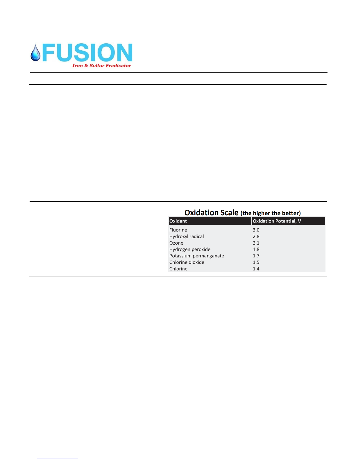
Hydrogen peroxide or H2O2 is a powerful, yet versatile oxidant that is both safe and effective.
Consider the H2O2 advantages and you’ll know why this is the ONLY sure way to eradicate
iron, manganese and sulfur.
Powerful - H2O2 is one of the most powerful oxidizers known and is much stronger than
chlorine, chlorine dioxide, and potassium permanganate.
Safe - H2O2 is formed by the action of sunlight on water and is a natural purification system for
our environment. Consequently, H2O2 has none of the problems of gaseous release or
chemical byproducts that are associated with other chemical oxidants. And since H2O2 is
totally miscible with water, it reverts back to hydrogen and oxygen after the reaction is
complete.
Versatile - Hydrogen Peroxide is lethal to iron, sulfur and manganese. PERIOD!
Selective - In itself, H2O2 is a fantastic oxidizer, much better than chlorine and potassium
permanganate. It poses no health hazard and ERADICATES 100% OF THE IRON, SULFUR
OR MANGANESE – ALL THE TIME – GUARANTEED!
Consult one of water specialists for higher flow rates. US Water offers OXi systems up to 100
GPM and can custom design them at no extra charge. Call us at 800-608-USWA or e-mail us
at info@uswatersystems.com .
3
Page 4
Installation, Operation and Maintenance Manual
Oxi-Gen Oxi-2P,3P,4P, 5P & 6P System
How Your Oxi-Gen Water Treatment System Works
The Oxi-Gen iron, sulfur and manganese eradication system uses Hydrogen Peroxide (H2O2)
to oxidize contaminants in your water source. The chemical name for hydrogen peroxide is
H2O2. As you can see it is very similar to water (H2O) but with one additional oxygen
molecule. Hydrogen peroxide is injected into the water stream proportionally. The chemical
injection control panel will engage the pump based on the flow rate of the feed source water
and the settings on the pump control.
When water is being used the water meter on the injection panel sends a pulse to the pump
control to engage the pump. So when large amounts of water is being used the pump will run
more frequently during the usage period than in times when a small amount of water is being
used.
When hydrogen peroxide is injected into the water stream, it oxidizes the iron, sulfur and
manganese from solution. This reaction is immediate. When these contaminants are oxidized
with hydrogen peroxide (H2O2) the extra oxygen molecule oxidizes the contaminants and the
by product is H2O (water). This is much safer than using chlorine in that chlorine can cause
other problems in the water stream such as chloramines and trihalomethanes (THM’s).
Once the water has been injected with hydrogen peroxide it passes through the backwashing
carbon filter. The backwashing carbon filter uses catalytic carbon to act as a “catalysis” to
remove the oxidized contaminants. As the water passes through carbon filter the oxidized
contaminants are removed from the water and collected on the carbon media. Once the water
has passed through the carbon filter the water is iron, sulfur and manganese free!
The carbon filter will need to be backwashed on a frequency (in days) to flush out the collected
contaminants. The frequency varies on each system depending on the contaminant level.
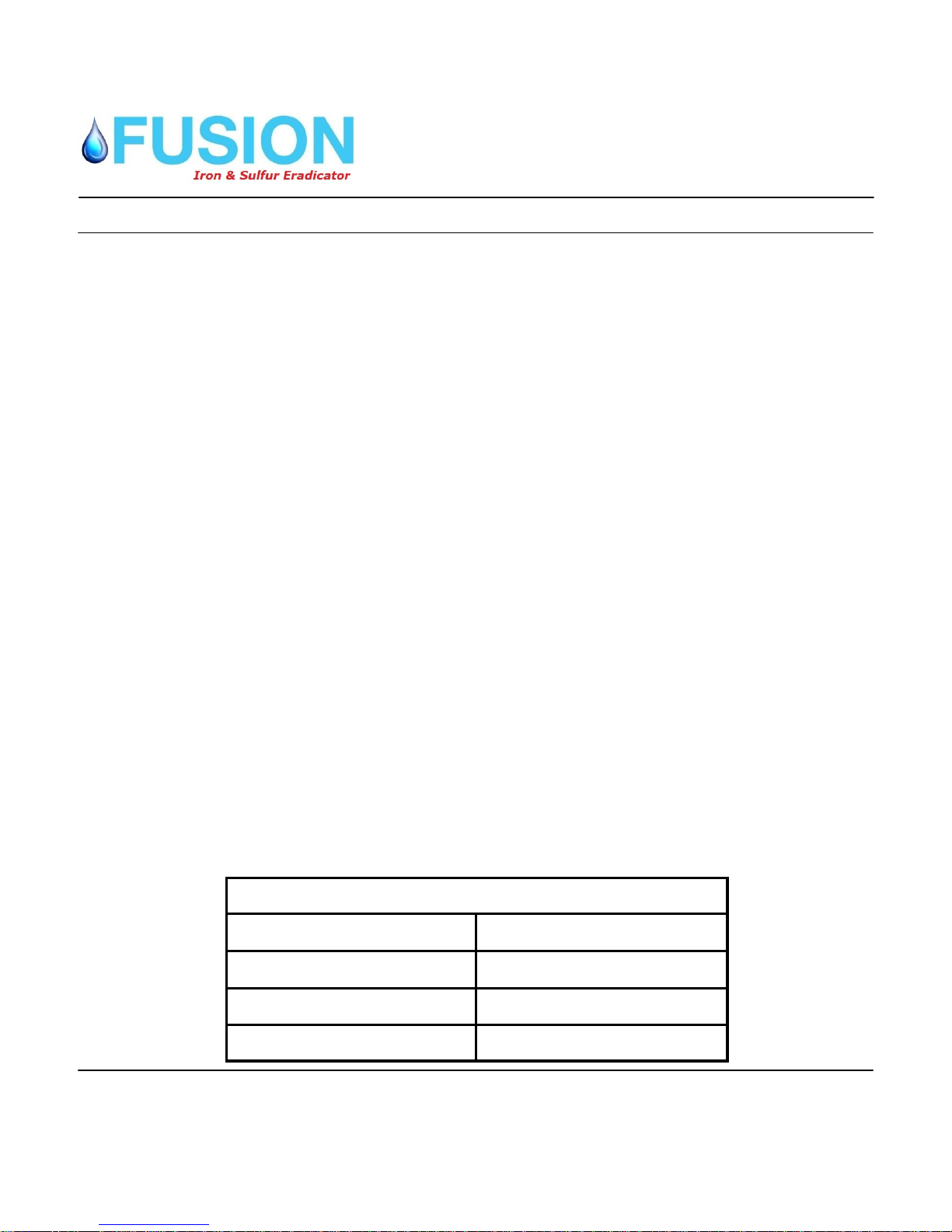
Please use the following table as a guideline for backwash frequency combining iron, sulfur
and manganese values (these are baseline values and actual frequency may vary);
Combined Contaminant Level Days Between Backwashes
1-3 ppm Combined 3 Days
Catalytic Carbon Backwash Frequency
3-6 ppm Combined 2 Days
>6 ppm Combined 1 Day
4
Page 5

Installation, Operation and Maintenance Manual
Oxi-Gen Oxi-2P,3P,4P, 5P & 6P System
System Components
Stenner Proportional Injection System Specifications
The Stenner Proportional Injection System delivers precise dosing
proportional to the system's flow rate based on water volume.
The Stenner system is perfectly suited for constant pressure (variable speed) well pumps, poultry and
livestock houses, irrigation, systems with demand based backup wells and any application with varying
flow rates
The primary components are the Stenner Pump Control Module, Stenner Classic Series Fixed Output Pump and a
dry contact pulsing Water Meter. The Stenner Pump Control Module is a time adjusted controller that powers the
pump. A pulsing water meter sends a signal to the Stenner PCM which actuates the pump to deliver the desired
dose based on water volume. The Stenner PCM has a locking dial to assure the accuracy of the dosage. The
Stenner Proportional Injection System can be utilized to inject any number of chemicals including chlorine,
hydrogen peroxide, polyphosphate, Rid-O-Rust and many other chemicals.
The Stenner Proportional Injection System includes brackets to easily mount the panel to the wall for timely
installations and equipment accessibility. It is completely "plug and play." Simple to install, even simpler to set.
Available in 120V, accommodates 3/4" or 1" piping. Just plug into any electrical outlet, intercept a 3/4" or 1" line
and connect it and you are done. It's that simple.
Flows up to 22 GPM
Panel & panel fittings: Polyethylene
Mounting hardware: Stainless steel
Piping and associated fittings: PVC
Water meter: bronze
Filter: PVC with polycarbonate cover and two polyester screens 30 and 100 mesh
Note: Connections are socket weld union ¾” connections
Dimensions: 36 x 23 x 11 in.
Shipping Weight: 31 lbs
5
Page 6

Installation, Operation and Maintenance Manual
System Components
Stenner Proportional Injection System Installation Instructions
Note: If there is sediment in the water, it should be removed prior to the injection system using a pleated filter and
or multi-media filter. Sediment will clog the injection panel filter and could damage the water meter and pump in
extreme cases.
IMPORTANT!
Key for optimum performance:
READ THE MANUALS for the Pump, PCM, Filter and Water Meter for proper safety and
complete operation instructions.
1. Select a dry location to mount panel to avoid water intrusion. When selecting the location,
note the water flow direction as indicated on the filter of the panel flow assembly. Location
should allow mounting hardware to be anchored into studs or concrete to support the
weight of the panel.
2. Isolate and depressurize the water system.
3. The length of the panel's slip socket connections clearance required is 31 1/4". For existing
water systems cut necessary length of pipe to insert panel.
NOTE: Two 1" to 3/4" reducer couplings are included in the accessory kit to allow unit to adapt to 1" piping
systems.
4. Mark location of lag bolt holes 12 3/8" above center line of the horizontal pipe.
5. Secure wall mount bracket to wall studs using the included lag bolts or other suitable
hardware. Hang panel on to wall mount bracket.
6. Glue stubbed cut pipe into slip socket. After glue is cured, hand tighten the union
connections.
7. Install one of the provided filter screens with o-ring into the filter body. For high turbidity
water, use the more porous screen (30 mesh). Install filter cover hand tight. Close ball valve
on filter cover.
8. Drill a 1/4” hole in the top of the solution tank and feed the 1/4” tubing through the hole.
Pull the end inside the tank out the fill hole and push the weighted strainer on the end of the
tubing. Now lower the weighted strainer so that it is about 3/4” off the bottom of the tank.
Connect the other end of the 1/4” tubing to the suction side of the pump (port closest to the
pump mount). DO NOT use wrenches or threading tape. Connection needs to be finger
tightened. Pour the Hydrogen Peroxide in the tank.
9. Attach discharge tubing into injection fitting with the remaining nut and ferrule.
10. Priming of Pump (Set PCM to 50)
a. Remove the four screws on the power cord cover and disconnect the pump power cord
from the PCM and plug into a 120V outlet or leave cover on and run a temporary extension
cord to the male end of the pump cord.
b. Turn pump power switch on and observe the chemical being drawn from the solution tank.
c. When chemical reaches the injection point turn pump off.
6
Page 7

Installation, Operation and Maintenance Manual
Oxi-Gen Oxi-2P,3P,4P, 5P & 6P System
System Components
11. Plug pump back into the PCM. Plug PCM power cord into a 120V receptacle and reinstall
cord cover if applicable.
12. Open the 2 ball valves slowly, pressurize system with water and turn pump power switch to
"on".
13. Run water through the system and fine tune chemical readings by adjusting the PCM dial.
If desired lock the PCM setting with set screw on the dial.
14. Slide roof into pump mounting bracket over motor.
WARNING When pressurizing the system gradually allow water to flow. Shocking the meter by over
speeding it with high flow rates can damage the internal assembly.
CAUTION Ensure the piping is properly supported both upstream and downstream of the panel.
FOR INDOOR USE ONLY.
It is the installer's responsibility to comply with all national and local plumbing and electrical codes.
The Proportional Injection
System has two screws
installed in each side of
the pump wall mount
bracket to prevent shipping damage. Please
remove the screws upon
installation so the pump
can be removed from the
bracket when required.
7
Page 8

Installation, Operation and Maintenance Manual
System Components
Media Installation
Assembly Instructions
1. Remove the tank from carton.
2. Verify the riser is still fully engaged in the Vortech plate.
3. Place a piece of duct tape over the riser tube so no media enters the riser while filling.
4. Make sure the riser is centered to facilitate the valve installation after installation
of the media.
5. Use the Funnel provided, to pour the media into the tank. Pour it evenly around the hole
to ensure it is well distributed in the tank and pour slow enough, to keep from plugging
the hole.
Important: It is a good practice to hold a shop vac close to the funnel to collect any
dust that escapes during the filling process. Safety glasses and a dust mask are recommended.
6. When media is installed move tank side to side to settle the media.
Oxi-Gen Oxi-2P,3P,4P, 5P & 6P System
Valve Installation
1. Remove the tape from the riser and discard.
2. Lubricate the two o-rings with a light coat of Silicone.
3. Install the Upper Basket (cone shaped screen) to the valve, twisting it to lock it in
place.
4. Slip the Upper Basket over the Riser sliding it down into place and screw the valve
on and tighten.
5. Follow the installation procedures in this manual and program accordingly.
8
Page 9

Installation, Operation and Maintenance Manual
Oxi-Gen Oxi-2P,3P,4P, 5P & 6P System
System Components
Carbon Filter Installation Instructions
WATER PRESSURE: A minimum of 20 pounds of water pressure is required for regeneration valve to operate effectively.
ELECTRICAL FACILITIES: An uninterrupted alternating current (A/C) supply is required. Note: Other voltages are available. Please make sure your voltage supply is compatible with your unit before installation.
EXISTING PLUMBING: Condition of existing plumbing should be free from lime and iron buildup. Piping that is built up
heavily with lime and/or iron should be replaced.
LOCATION OF FILTER AND DRAIN: The filter should be located close to a drain to prevent air breaks and back flow.
BY-PASS VALVES: Always provide for the installation of a by-pass valve if unit is not equipped with one.
CAUTION: Water pressure is not to exceed 125 psi, water temperature is not to exceed 110°F, and the unit cannot be subjected to freezing conditions.
1. Place the filter tank where you want to install the unit making sure the unit is level and on a
firm base.
2. During cold weather, the installer should warm the valve to room temperature before operat-
ing.
3. All plumbing should be done in accordance with local plumbing codes. The pipe size for
residential drain line should be a minimum of 1/2". Backwash flow rates in excess of 7
gpm or length in excess of 20’ require 3/4" drain line. Commercial drain lines should be
the same size as the drain line flow control.
4. The inlet on the bypass valve is indicated by an arrow that will point toward the valve.
The outlet will be indicated by an arrow pointing away from the valve.
5. Lubricate the distributor o-ring seal and tank "o" ring seal. Place the main control valve on
tank. Note: Only use silicone lubricant.
6. Solder joints near the drain must be done prior to connecting the Drain Line Flow Control
fitting (DLFC). Leave at least 6" between the DLFC and solder joints when soldering pipes
that are connected on the DLFC. Failure to do this could cause interior damage to the
DLFC.
7. Teflon tape is the only sealant to be used on the drain fitting.
8. On units with a by-pass, place in by-pass position. Turn on the main water supply. Open a
cold water tap nearby and let run a few minutes or until the system is free from foreign material (usually solder) that may have resulted from the installation. Once clean, close the water tap.
9. Slowly place the by-pass in service position and let water flow into the media tank until the
water flow stops.
10. Plug unit into an electrical outlet. Note: All electrical connections must be connected accord-
ing to local codes. (Be certain the outlet is uninterrupted).
9
Page 10

System Components
Carbon Filter Control Valve Features
Timer Features
Installation, Operation and Maintenance Manual
Oxi-Gen Oxi-2P,3P,4P, 5P & 6P System
Error/
Information
Icon
Pa ram ete r Data PM
Display Display Indicator
S e r v i c e
Icon
Flow Indicator
x1000 Indicator
Programming
Icon
Extra Cycle
Button
Up
B u tt on
D o wn
B u tt on
Features of the SXT:
Power backup that continues to keep time and the passage of days for a minimum of 48 hours
in the event of power failure. During a power outage, the control goes into a power-saving
mode. It does not monitor water usage during a power failure, but it does store the days remaining at the time of power failure.
Settings for both valve (basic system) and control type (method used to trigger a regeneration).
Day-of-the-Week controls.
While in service, the display alternates between time of day and days to regeneration.
The Service Icon flashes if a backwash cycle has been queued.
A backwash can be triggered immediately by pressing the Extra Cycle button for five seconds.
The Parameter Display displays the current Cycle Step (BW, RR, etc) during backwash, and the
data display counts down the time remaining for that cycle step. While the valve is transferring
to a new cycle step, the display will flash. The parameter display will identify the destination cycle step (BW, RR, etc) and the data display will read "----". Once the valve reaches the cycle
step, the display will stop flashing and the data display will change to the time remaining. During
regeneration, the user can force the control to advance to the next cycle step immediately by
pressing the extra cycle button.
10
Page 11
Installation, Operation and Maintenance Manual
Oxi-Gen Oxi-2P,3P,4P, 5P & 6P System
System Components
Carbon Filter Control Valve Features
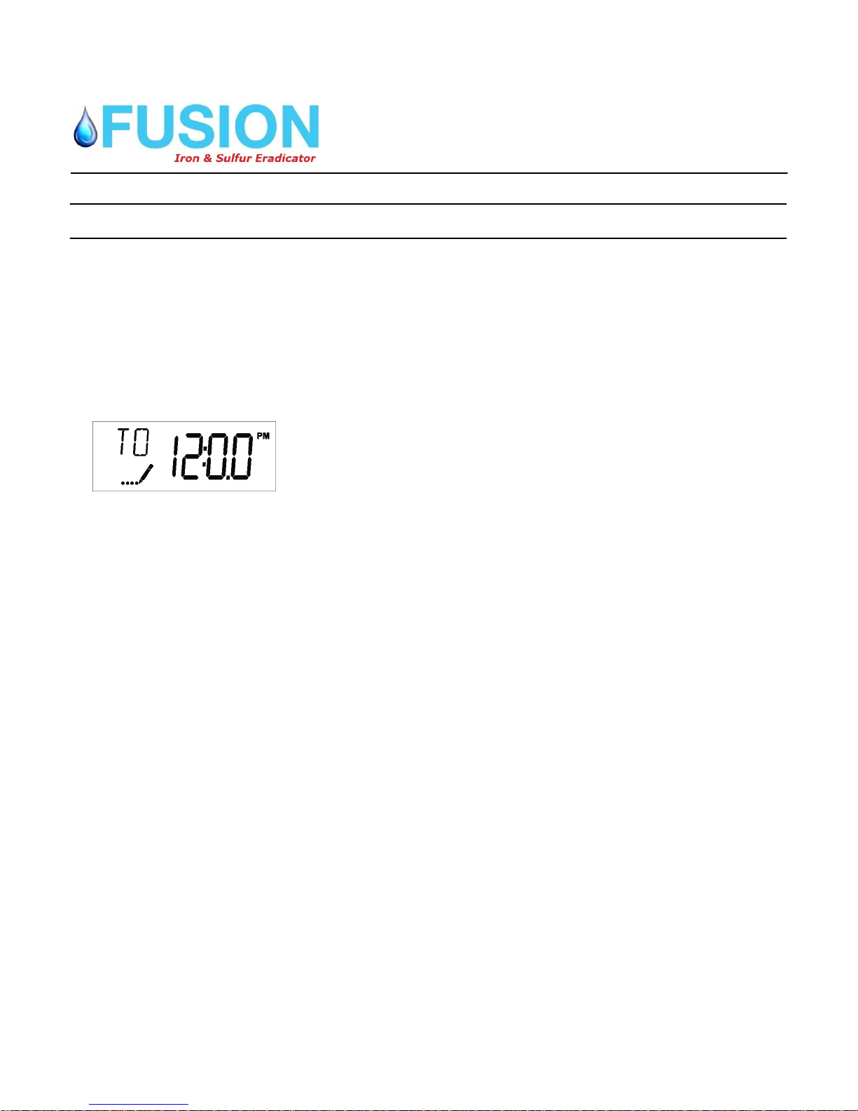
Setting the Time of Day
1. Press and hold either the Up or Down buttons until the programming icon replaces the
service icon and the parameter display reads TD.
2. Adjust the displayed time with the Up and Down buttons.
3. When the desired time is set, press the Extra Cycle button to resume normal opera-
tion. The unit will also return to normal operation after 5 seconds if no buttons are
pressed.
Queueing a Backwash
1. Press the Extra Cycle button. The service icon will flash to indicate that a backwash is queued.
2. To cancel a queued backwash, press the Extra Cycle button.
Backwashing Immediately
Press and hold the Extra Cycle button for five seconds.
Time Clock Delayed Control
A Time Clock Delayed Control regenerates the system on a timed interval. The control will
initiate a backwash cycle at the programmed backwash time when the number of days
since the last backwash equals the backwash day override value.
Day of the Week Control
This control regenerates the system on a weekly schedule. The schedule is defined in Mas-
ter Programming by setting each day to either "off" or "on." The control will initiates a regeneration cycle on days that have been set to "on" at the specified regeneration time.
Control Operation During Programming
The control only enters the Program Mode with the valve in service. Control programming
is stored in memory permanently, eliminating the need for battery backup power.
Manually Initiating a Backwash
1. When timer is in service, press the Extra Cycle button for 5 seconds on the main screen.
2. The timer advances to Backwash Cycle Step #1 (backwash), and begins programmed time
count down.
3. Press the Extra Cycle button once to advance valve to Regeneration Cycle Step #2 (brine
rapid rinse).
4. Press the Extra Cycle button once more to advance the valve back to in service.
11
Page 12

Installation, Operation and Maintenance Manual
Oxi-Gen Oxi-2P,3P,4P, 5P & 6P System
Carbon Filter Control Valve Features and Programming
Control Operation During A Power Failure
The SXT includes integral power backup. In the event of power failure, the control shifts into a
power-saving mode. The control stops monitoring water usage, and the display and motor shut
down, but it continues to keep track of the time and day for a minimum of 48 hours.
The system configuration settings are stored in a non-volatile memory and are stored indefinitely
with or without line power. The Time of Day flashes when there has been a power failure. Press
any button to stop the Time of Day from flashing.
If power fails while the unit is in regeneration, the control will save the current valve position before it shuts down. When power is restored, the control will resume the regeneration cycle from
the point where power failed. Note that if power fails during a regeneration cycle, the valve will
remain in it's current position until power is restored. The valve system should include all required safety components to prevent overflows resulting from a power failure during regeneration. The control will not start a new backwash cycle without line power.
Master Programming Mode
When the Master Programming Mode is entered, all available option setting displays may be
viewed and set as needed. Depending on current option settings, some parameters cannot be
viewed or set. Use the following chart to program your filter. You will use the highlighted values. Items not highlighted either do not require a change or do not appear in filter mode.
Entering Master Programming Mode
Set the Time Of Day display to 12:01 P.M. Press the “extra cycle”. Then press and hold the Up
and Down buttons together until the programming icon replaces the service icon and the Display
Format screen appears. The extra cycle button will serve as an “enter/save” button. The up
and down arrows are used to change the value of each parameter and the extra cycle button
saves the parameter changes and will move the control to the next programming parameter.
Exiting Master Programming Mode
Press the Extra Cycle button to accept the displayed settings and cycle to the next parameter.
Press the Extra Cycle button at the last parameter to save all settings and return to normal operation. The control will automatically disregard any programming changes and return to normal
operation if it is left in Master Programming mode for 5 minutes without any keypad input.
Soft Reset: Press and hold the Extra Cycle and Down buttons for 25 seconds while in normal Service mode.
This resets all parameters to the system default values, except the volume remaining in meter immediate or meter de-
layed systems and days since regeneration in the time clock system.
Master Reset: Hold the Extra Cycle button while powering up the unit. This resets all of the parameters in the unit.
Check and verify the choices selected in Master Programming Mode.
Please use the following chart to program the carbon filter control valve. Use the highlighted settings. Days between backwashes will be determined using the chart on page
#4. Some parameters will not be shown depending on the valve configuration.
12
Page 13

Carbon Filter Control Valve Programming
Master Programming Options
Abbreviation Parameter Option
Abbreviation
GAL Gallons
DF Display Format
VT Valve Type
CT
NT
Control Type
Number of Tanks
Ur Liters
Cu Cubic Meters
dF1b
.
dF2b Standard Downflow/Upflow Double Backwash
Fltr Filter
UFbF Upfiow Brine First
Othr Other
Fd Meter (Flow) Delayed
Fl Meter (Flow) Immediate
tc Time Clock
dAY Day of Week
1 Single Tank System
2 Two Tank System
Ul Tank 1 in Service
Installation, Operation and Maintenance Manual
Oxi-Gen Oxi-2P,3P,4P, 5P & 6P System
Options
Standard Downflow/Upflow Single Backwash
TS
C Unit Capacity
H
RS Reserve Selection
Tank in Service
Feedwater
Hardness
SF Safety Factor
RC
DO Day Override
RT Regen Time 2:00 The time of day the system will regenerate
BW, BD, RR,
BF
D1, 02, D3, D4,
D5, 06, & D7
CD Current Day
Fixed Reserve Capacity
Regen Cycle Step
Times
Day of Week
Settings
U2 Tank 2 in Service
rc Fixed Reserve Capacity
1-99
No
Changes
Here
Unit Capacity (Grains)
Hardness of Inlet Water
Percentage Safety Factor
Percentage of the system capacity to be used as a
reserve
Fixed volume to be used as a reserve
The system's day override setting
The time duration for each regeneration step. Adjustable from OFF and 0-199 minutes.
NOTE: If "Othr" is chosen under "Valve Type", then
RI, R2, R3, etc, will be displayed instead
Regeneration setting (On or OFF) for each day of the
week on day-of-week systems
The Current day of the week
13
Page 14

Installation, Operation and Maintenance Manual
Oxi-Gen Oxi-2P,3P,4P, 5P & 6P System
Carbon Filter Start Up Procedure
The water filter should be installed with the inlet, outlet, and drain connections made in
accordance with the manufacturer's recommendations, and to meet applicable plumbing
codes.
1. Push and hold the “extra cycle” button (far left button with triangle shaped arrows on the but-
ton). This button will advance the valve to the next cycle if it is pushed and released.
2. This will position the valve to backwash. You will see BW and four dashes. The four dashes
will change to a time value that will start to count down. Once the time begins to count
down. Slowly open the bypass valve to the service position. Ensure the drain line flow remains steady for 10 minutes or until the water runs clear.
3. After the backwash cycle, the valve will move to the rapid rinse position. Check the drain line
flow, and run for 5-10 minutes or until the water runs clear.
4. The filter is now installed.
H2O2 Injection Setting
US Water Systems uses the “bubble method”. This is a visual method that works best for quick
and reliable H2O2 injection rates.
1. Set the proportional control on the Stenner injection panel (gray wall mount panel) to 40%
(there is a dial on the little black box (PCM) that the pump is plugged in to).
2. Run water for 10-15 minutes.
3. Take a sample after the carbon tank (or at a sink). The water in the sample container
(preferably glass) should be full of bubbles immediately after the sample is taken. If not the
installer will adjust the knob to 50%, run the water for 10-15 minutes and check again.
4. Continue adjusting the knob up in increments of 10% until the sample container is full of bubbles. Once the container is full of bubbles, it is an indicator that there is plenty of H2O2 in
the water.
5. Continue the same process decreasing the knob setting in 5% increments allowing the water
to run for 10-15 minutes between adjustments until there are just a few bubbles in the sample container (20-30 defined air bubbles) that come to the top of the water level and dissipate
immediately. This should be the optimal H2O2 injection setting.
This is an indicator that there is a small amount of residual H2O2 in the treated water and the contaminant
is being oxidized. Once this setting is determined the system will operate automatically.
Over the first 1-3 months it is important to monitor the H2O2 level in the storage/solution tank and start to
gain usage data that will help you determine the H2O2 usage and allow you to plan/order replenishment
H2O2 accordingly. This setting should be periodically checked and adjusted due to changes in the aquifer (well) and loss of H2O2 concentration by degradation. After 6-8 months the H2O2 can lose concentration, so only replenish the tank to a level that can be used in 6-8 months to ensure the H2O2 concentration
strength is consistent.
14
Page 15

Installation, Operation and Maintenance Manual
Oxi-Gen Oxi-2P,3P,4P, 5P & 6P System
What To Expect and Routine Maintenance
Now that the Oxi-Gen system has been installed here are a few things to expect;
1. The Oxi-Gen system will produce iron, sulfur and manganese free water immediately after
installation. Depending on the raw water quality there may be contaminants built up in the
water heater, plumbing system and other devices. Over the first few weeks as water is
used there could be traces of this build up that are being removed by the newly installed
system. This typically clears up after a couple weeks.
2. Depending on the contaminants being removed there may be iron bacteria or sulfur reducing bacteria in the plumbing system prior to the Oxi-Gen install. This bacteria can potentially survive after the Oxi-Gen installation. This is usually indicated by a sulfur smell that will
appear after a few weeks of initial usage. If this is the case, the well and entire plumbing
system will need to be chlorinated to remove any existing bacteria. If the bacteria is not removed, it will begin to “grow” backwards toward the treatment system and the sulfur smell
will not go away. If this does occur, it is easily eradicated with a chlorination procedure.
3. There may be “bubbles” in the water for a few weeks after installation. A few bubbles are
fine, but if there is “fizz” that remains for several seconds, it is an indication that the system
is being overfed with H2O2. This occurs because after installation the water will become
cleaner and the initial dosage of H2O2 may need to be adjusted to compensate for the lower contaminant level.
Routine Maintenance
Pressure Tank
If your plumbing system uses a bladder pressure tank it will be in the system prior to the OxiGen system. This tank should be drained periodically to remove the build up of contaminants.
Typically once a quarter is sufficient but that frequency may need to be increased on systems
with high contaminant levels.
Injection Panel
Sediment Filter/Strainer
The inline sediment filter on the injection panel has a “blow down” valve at the bottom. This
filter should be blown down once a month to clear collected sediment. If there is high levels of
sediment in the filter it may need to be removed and cleaned.
Pump Tube
The internal pump tube may need to be replaced periodically. They typically last 1-5 years depending on the usage. There is a spare tube shipped with the system and instructional videos
explaining how to change the tube at www.USWaterSystems.com.
Carbon Filter
The carbon filter is virtually maintenance free. However, if there is a power outage the clock
and other settings need to be checked to ensure the filter will backwash properly at the proper
time of day. It is crucial that the carbon filter backwashes at a time when there is no water being used in the house.
15
Page 16

Installation, Operation and Maintenance Manual
Oxi-Gen Oxi-2P,3P,4P, 5P & 6P System
Maintenance Schedule
Component Action Frequency Replacement
Part #
Existing Well Pressure
Tank
Injection Panel Sediment Filter
Injection Panel Pump
Tube
Injection Panel Duck
Bill Check Valve
Drain tank until the water runs
clear.
Open blow down valve and
flush the filter.
Inspect pump tube and replace
as needed. #2 Tube.
Replace injection check valve
as needed.
H2O2 Solution Tank Periodically check the solution
level and refill as needed.
Carbon Tank Check the clock and settings
periodically or after a power
outage.
1-6 Months N/A
3-6 Months N/A
1-5 Years 411-UCCP202
1-5 Years 411-UCCVDBO
Varies by wa-
710-HP22N
ter usage.
4 Months N/A
16
Page 17

Installation, Operation and Maintenance Manual
Oxi-Gen Oxi-2P,3P,4P, 5P & 6P System
Flow Schematic
17
Page 18

Installation, Operation and Maintenance Manual
Oxi-Gen Oxi-2P,3P,4P, 5P & 6P System
Warranty
Oxi-Gen
Limited Lifetime Warranty
For the lifetime of the original purchaser, at the original residential
place of installation of this OxiGen Water Treatment System, US WA-
TER SYSTEMS, INC. warrants the following:
Free of all costs to you except transportation and labor charges, we
warrant that we will replace or repair the fiberglass media and hydrogen peroxide storage tank, if for any reason it is found to be defective,
because of faulty materials or workmanship.
We warrant that for five (5) years from the date of installation, we will
replace the Backwashing Filter Valve and Electronics free of charge to
you except for transportation and standard labor charges.
We warrant that for two (2) years from the date of installation, we will
replace the STENNER Pump & Catalytic Media free of charge to you
except for transportation and standard labor charges.
This warranty does not apply to any commercial or industrial installations or to any part of the water conditioner which has been subjected
to misuse, neglect, alteration or accident; or to any damage caused
by fire, flood, freezing, Acts of God, or any other casualty, or if the
original serial numbers have been removed. Fouling or damage to
the resin caused by iron, sulfur, bacterial iron, silt, sand, tannins, organics, bacteria, hot water or chlorine voids the warranty on resin.
LIFETIME COVERAGE
Media Tank(s)
Hydrogen Peroxide Solution Tank
FIVE YEAR COVERAGE
Electronics
Drive Motor
TWO YEAR COVERAGE
STENNER PUMP
Catalytic Media
GENERAL PROVISIONS
These warranties are in lieu of all other warranties expressed
or implied, and we do not authorize any person to assume for us any
other obligation on the sale of this water conditioner. No responsibility is assumed for delays or failure to meet these warranties caused
by strike, government regulations or other circumstances beyond the
control of US WATER SYSTEMS, INC..
TO OBTAIN WARRANTY SERVICE, CALL OR WRITE: US WATER SYS-
TEMS, INC. 1209 COUNTRY CLUB ROAD INDIANAPOLIS, IN 46234
(317) 271-8600.
ANY IMPLIED WARRANTIES OF FITNESS OR MERCHANTABILITY
ARE LIMITED TO THE TERMS OF THIS EXPRESSED WARRANTY
AND THERE ARE NO WARRANTIES WHICH EXTEND BEYOND
THOSE HEREIN. US WATER SHALL NOT BE LIABLE FOR ANY
INCIDENTIAL OR CONSEQUENTIAL DAMAGES.
SOME STATES DO NOT ALLOW THE EXCLUSION OR LIMITATIONS OF INCIDENTAL OR CONSEQUENTIAL DAMAGES SO THE
ABOVE LIMITATION MAY NOT APPLY TO YOU. THIS WARRANTY
GIVES YOU SPECIFIC LEGAL RIGHTS, AND YOU MAY ALSO
HAVE OTHER RIGHTS WHICH VARY FROM STATE TO STATE.
THIS WARRANTY MAY BE TRANSFRRED TO A SUBSEQUENT
OWNER WITH WRITTEN APPROVAL OF US WATER AND PAY-
MENT OF STANDARD TRANSFER FEE.
FOR YOUR RECORDS:
Model _________________________________________
Serial __________________________________________
Date Installed ___________________________________
18
 Loading...