

Page 1

OPERATOR'S MANUAL
VOYAGE DATA RECORDER
SIMPLIFED VOYAGE DATA RECORDER
VR-3000
MODEL
VR-3000S
www.furuno.co.jp
Page 2
9-52 Ashihara-cho,
*
00015707816
**00015707816
*
Nishinomiya, 662-8580, JAPAN
Telephone : +81-(0)798-65-2111
Fax :+81-(0)798-65-4200
The paper used in this manual
is elemental chlorine free.
・FURUNO Authorized Distributor/Dealer
All rights reserved.
Pub. No. OME-44370-G1
(TATA ) VR-3000/3000S
Printed in Japan
A : APR 2006
.
G1 : NOV . 24, 2010
*00015707816**00015707816*
* 0 0 0 1 5 7 0 7 8 1 6 *
Page 3
IMPORTANT NOTICES
Cd
General
• The operator of this equipment must read and follow the descriptions in this manual. Wrong
operation or maintenance can cancel the warranty or cause injury.
• Do not copy any part of this manual without written permission from FURUNO.
• If this manual is lost or worn, contact your dealer about replacement.
• The contents of this manual and equipment specifications can change without notice.
• The example screens (or illustrations) shown in this manual can be different from the screens
you see on your display. The screens you see depend on your system configuration and
equipment settings.
• Save this manual for future reference.
• Any modification of the equipment (including software) by persons not authorized by FURUNO
will cancel the warranty.
• All brand and product names are trademarks, registered trademarks or service marks of their
respective holders.
How to discard this product
Discard this product according to local regulations for the disposal of industrial waste. For
disposal in the USA, see the homepage of the Electronics Industries Alliance
(http://www.eiae.org/) for the correct method of disposal.
How to discard a used battery
Some FURUNO products have a battery(ies). To see if your product has a battery, see the
chapter on Maintenance. Follow the instructions below if a battery is used. Tape the + and terminals of battery before disposal to prevent fire, heat generation caused by short circuit.
In the European Union
The crossed-out trash can symbol indicates that all types of
batteries must not be discarded in standard trash, or at a trash site.
Take the used batteries to a battery collection site according to your
national legislation and the Batteries Directive 2006/66/EU.
In the USA
The Mobius loop symbol (three chasing arrows) indicates that Ni-Cd
and lead-acid rechargeable batteries must be recycled. Take the used
batteries to a battery collection site according to local laws.
Ni-Cd Pb
In the other countries
There are no international standards for the battery recycle symbol. The number of symbols can
increase when the other countries make their own recycling symbols in the future.
i
Page 4
SAFETY INSTRUCTIONS
WARNING
ELECTRICAL SHOCK HAZARD
Do not open the equipment.
Only qualified personnel
should work inside the
equipment.
Do not disassemble or modify the
equipment.
Fire, electrical shock or serious injury can
result.
Immediately turn off the power
(BATTERY, DC and AC switches in
that order) at the DCU and also turn off
off the power at the ship's mains
switchboard if water leaks into the
equipment or the equipment is emitting
smoke or fire.
Continued use can cause fatal damage to
the equipment.
WARNING
Do not disassemble the battery.
Battery fluid is harmful to the eyes and skin,
particularly the eyes. If the fluid contacts
skin or eyes, flush area with fresh water
and contact a physician immediately.
Do not dispose of the battery or acoustic
beacon in fire.
Those components may burst if disposed of
in fire. Further, dispose of the battery in
accordance with appropriate regulations.
Do not touch any electricaly conductive
parts.
Touching electrically conductive parts can
result in electrical shock. Use rubber gloves,
etc. when conducting inspection or
maintenance work.
Do not short battery terminals.
Only authorized personnel shall
disassemble the DRU.
Pressure may build up inside the unit when
it is subjected to fire or is retrieved from a
great depth.
Do not allow rain or water splash to
contact the equipment.
Fire or electrical shock can result.
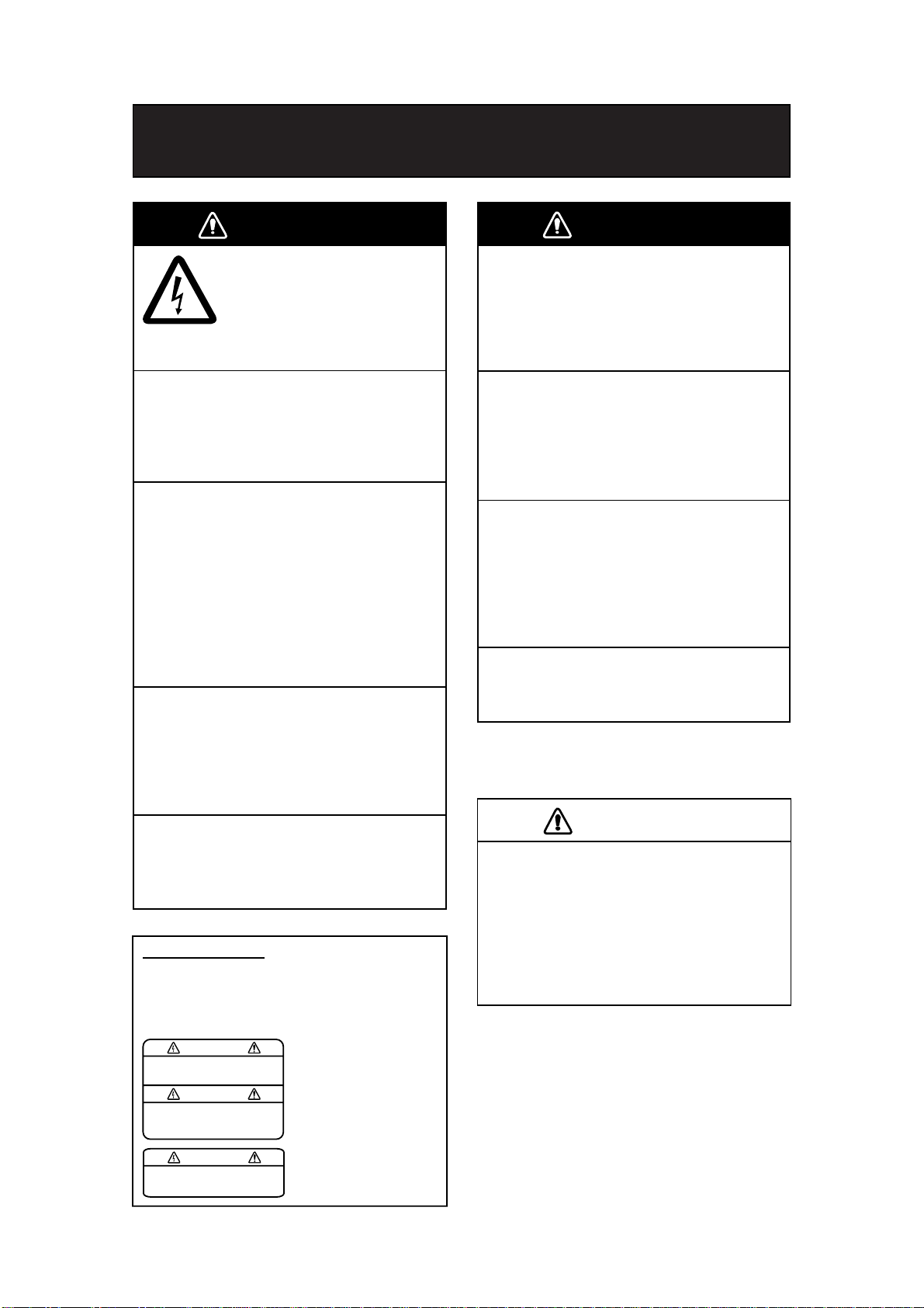
WARNING LABELS
Warning labels are attached to the DCU.
Do not remove the labels. If the label is missing or
damaged, contact a FURUNO agent or dealer
about replacement.
WARNING
To avoid electrical shock, do not
remove cover. No user-serviceable
parts inside.
Name: Warning Label 1
Type: 86-003-1011-2
Code No.: 100-236-232-10
Short can lead to bursting or fire.
CAUTION
Do not:
- use batteries of different capacities
- mix old batteries with new
- mix batteries of different makes
Batteries themselves may become
damaged or damage to electrical
parts may result.
WARNING
To avoid electrical shock, do not
remove cover. No user-serviceable
parts inside.
Name: Warning Label 2
Type: 03-129-1001-2
Code No.: 100-236-742-10
ii
Page 5
POWERING DATA COLLECTING UNIT
On the power control panel in the Data Collecting Unit (DCU), confirm that the status display
shows “- - -“ and the NORMAL LED is lit after the power has been on for two minutes. If not, see
Chapter 3.
Procedure for turning on power
1. Turn the AC breaker switch on.
2. Turn the DC breaker switch on if DC power is connected.
3. Turn the BATTERY BACKUP breaker switch on.
Status Display
NORMAL LED
Breaker switches (from left)
Battery Backup, DC, AC
Power control panel/status display inside the DCU
Error indication on Remote Alarm Panel (RAP)
If the ERROR LED (red) lights on the RAP, check the error number on its status display and refer
to the error code tables in Chapter 3.
ERROR LED
Remote Alarm Panel
iii
Page 6

IF AN INCIDENT OCCURS
Press the SAVE button on the Remote Alarm Panel. Bring the HDD with you after an incident
occurs, if possible.
SAVE LED
(yellow)
SAVE button
• The SAVE LED (yellow) starts flashing and shortly thereafter lights. Then, recording to the
current memory area in the backup HDD in the Data Collecting Unit is stopped and recording
to another memory area starts. The memory in the backup HDD is divided into four areas.
If you press the SAVE button on the RAP, one recording area stops recording. If you press
the SAVE button four times, all four areas stop recording. If you pressed the SAVE button,
consult a FURUNO dealer to restore the HDD after an investigation of the incident is
completed by the authorities.
• Recording at the Data Recording Unit continues.
iv
Page 7

TABLE OF CONTENTS
FOREWORD...............................................................................................vi
SYSTEM CONFIGURATION......................................................................vii
Record of PUB REV., PROG. No.............................................................viii
1. OPERATION............................................................................................ 1
1.1 Overview ...........................................................................................................................1
1.2 Operating Procedure.........................................................................................................6
1.2.1 Powering, recording........................................................................................................6
1.2.2 Stopping recording..........................................................................................................6
1.3 Operation on Remote Alarm Panel ...................................................................................7
1.4 Removing HDD at an Incident...........................................................................................8
1.5 How to Release DRU ........................................................................................................8
2. MAINTENANCE.......................................................................................9
2.1 Annual Recertification .......................................................................................................9
2.2 Cleaning ............................................................................................................................9
2.3 Software Maintenance ....................................................................................................10
2.3.1 Software list ..................................................................................................................10
2.3.2 Checking software version of system program .............................................................10
2.3.3 Checking software version of RAP ...............................................................................10
2.4 Replacing Batteries ......................................................................................................... 11
2.5 Replacing Acoustic Beacon.............................................................................................12
2.6 Replacing Backup HDD ..................................................................................................13
2.7 Replacing Fuses .............................................................................................................14
2.8 Replacing Parts...............................................................................................................14
2.9 Verifying Recording Function of the DRU.........................................................................15
2.10 Confirmation of Peripheral Devices ................................................................................16
3. TROUBLESHOOTING...........................................................................17
3.1 General Troubleshooting.................................................................................................17
3.2 Error Codes.....................................................................................................................18
3.3 Testing Display of Remote Alarm Panel..........................................................................20
4. LOCATION OF PARTS.......................................................................... 21
4.1 Parts Location .................................................................................................................21
4.1.1 Data Collecting Unit (VR-3010) ....................................................................................21
4.1.2 Data Recording Unit (VR-5020-9G or VR-5020-6G) ....................................................22
4.1.3 Junction Box (IF-8530) .................................................................................................23
4.1.4 Remote Alarm Panel (VR-3016)...................................................................................23
4.2 Parts List .........................................................................................................................24
5. INTERFACE (IEC 61162-1, IEC 61162-2)..............................................25
5.1 Data Sentences...............................................................................................................25
5.2 Interface Circuits .............................................................................................................38
5.2.1 IEC 61162-1..................................................................................................................38
5.2.2 IEC 61162-2..................................................................................................................39
APPENDIX: PLAYING BACK RECORDED DATA.................................... 40
SPECIFICATIONS.......................................................................................................SP-1
v
Page 8

FOREWORD
A Word to the Owner of the VR-3000, VR-3000S
Thank you for purchasing the FURUNO Voyage Data Recorder (VDR) VR-3000, Simplified
Voyage Data Recorder (S-VDR) VR-3000S. We are confident you will discover why FURUNO
has become synonymous with quality and reliability.
What is a VDR, S-VDR?
A VDR records various data and events encountered aboard ship. The purpose of the VDR is to
help investigators locate the causes of marine incidents. There is no principle difference between
a VDR and an S-VDR. The difference is the amount of information required to be recorded. The
VDR is required to record more data than the S-VDR. Note that this manual refers to either the
VDR or S-VDR as VDR.
The revised SOLAS Chapter V requires the installation of VDRs on passenger ships of 150 GT
and above on all voyages and other ships of 3000 GT and above on international voyages and for
newly built ships on and after 1 July, 2002.
The basic VR-3000/VR-3000S consists of a Data Collecting Unit (DCU), a Data Recording Unit
(DRU), a Remote Alarm Panel (RAP) and microphones to record bridge audio. The VR-3000 is
also equipped with a Junction Box (JB), which is optional on the VR-3000S. The DCU contains
the Data Processor Unit, interface modules and backup batteries. It collects data from sensors as
required by the IMO and IEC standards. The DCU processes the incoming data and information
in the order of occurrence while old data is overwritten with new data for storage in the DRU for a
12 h period. The batteries supply power to the DCU to record bridge audio for 2 h in case of a
main ship’s power failure.
The flash memory in the DRU stores the data coming from the DCU. All essential navigation and
status data including bridge conversation, VHF communications, and radar images are recorded.
The data can be retrieved by using playback software for investigation after an incident. The DRU
components are embodied in the protective capsule. The capsule ensures survival and recovery
of the recorded data after an incident. An acoustical pinger helps locate the DRU underwater.
Features
• Reliable and fast data exchange between DCU and DRU via a single IEEE1394 cable.
• Easy commissioning and maintenance by PC downloading/uploading.
• 12-hour recording of normal sensor loading in standard memory.
• UTC time tagged for system synchronization and easy data retrieval.
• Choice of flash memory capacity in the Data Recording Unit.
• Backup hard disk (HDD) for storage and retrieval of data.
• Meets IMO A.861 (20), IEC 61996 and other relevant standards.
vi
Page 9
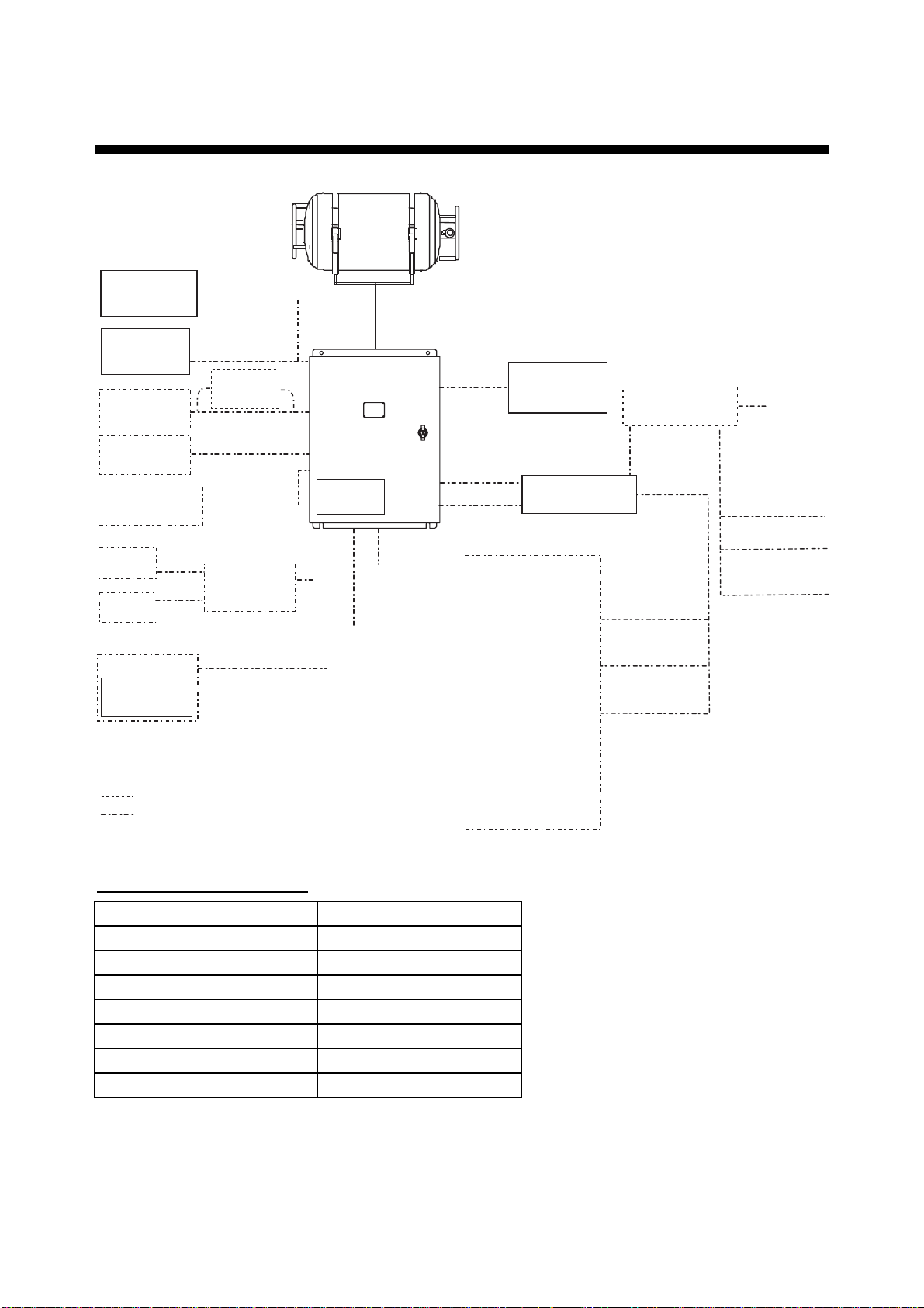
SYSTEM CONFIGURATION
Data Recording Unit (DRU)
VR-5020-6G/VR-5020-9G
Waterproof MIC
VR-3012W
Bridge MIC
VR-5011
VHF Audio
IEC 61162
serial data
Alarm Monitoring
System
No. 1
Radar
No. 2
Radar
PC
Live Player V4
VR-3020
: Standard supply equipment and cable
: Optional supply equipment and cable
: Local supply equipment and cable
* Optional with VR-3000S
Max. 6 ch
VHF I/F
IF-5200
Serial (Max. 8 ch)
Radar Video
SW Interface
IF-1000RVC
Max. 2 ch
Max.
2 ch
Data Collecting
Unit (DCU)
VR-3010
Radar I/F
RI-3010*
100-230 VAC
24 VDC
Remote Alarm
Panel (RAP)
VR-3016
Junction Box (JB)
IF-8530*
GPS
Speed log
Heading
Echosounder
Autopilot
Engine telegraph
Steering gear
M/E remote system
Main air compressor
Bow thruster
Shell door system
Watertight doors
Fire doors
Anemometer
Fire detection
Main alarms
Others
Junction Box (JB)
IF-8530 (max. 2)
Serial
(1ch)
Serial (Max. 8)
Analog
(Max. 16 ch)
Digital (Max. 64 ch)
24 VDC
Analog
(Max. 16 ch)
Digital (Max. 64 ch)
Serial (1 ch)
Environmental category
DCU Protected from weather
DRU Exposed to weather
RAP Protected from weather
Bridge MIC Protected from weather
Waterproof MIC Exposed to weather
VHF I/F unit Protected from weather
JB Protected from weather
Radar Video SW Interface Protected from weather
For the S-VDR, where it is impossible to obtain radar data, the AIS target data should be recorded
as a source of information from other ships. (Ref. IMO Res.MSC.163(78), section 5.4.7.)
vii
Page 10

RECORD OF PUB REV., PROG. NO.
Revision No.,
Date of Revision
A
Apr. 19, 2006
A1
June 2, 2006
B
June 16, 2006
C
July 24, 2006
D
May 17, 2007
E
July 9, 2008
F
Dec 15, 2008
G
Jul. 20, 2010
Program No.
(software)
VR-3000 SYSTEM
2450031-01
RAP
2450026-01
Same as above
Same as above
Same as above
Same as above
VR-3000 SYSTEM
2450031-02
RAP
Same as above
Same as above
Same as above
Outline of Revision
st
1
printing.
Revised system configuration drawings to include
Waterproof MIC.
Changed error code no. as follows:
035→034 Storage failure
041→042 Grabber failure
048→046 DRU Index error
Revised specifications
All pages revised.
Added beacon cover.
Changed flush disk.
For new standard.
Miner program modification
Miner program modification
Revised the replacing parts.
Added error codes; 173, 174, 431 and 432.
Revised section 2.9.
viii
Page 11

1. OPERATION
1.1 Overview
The VR-3000/VR-3000S consists of Data Collecting Unit (DCU), Data Recording Unit (DRU),
Remote Alarm Panel (RAP), Junction Box (JB, optional supply with VR-3000S) and bridge
microphone units. The VDR system continuously stores data from the past 12 hours onto the
Flash Memory in the capsule, erasing the oldest data stored as new data is recorded. The data to
be recorded includes the following:
Parameters to be recorded IEC 61162 formatter Notes
Date and time ZDA
Ship’s position and datum used GNS and DTM
Speed (water and/or ground) VBW
Heading (true) HDT
Heading (magnetic) HDG
AIS-VHF data-link message VDM
AIS-VHF data-link own-vessel message VDO
Depth (echo sounder) DPT
Alarms ALR
Rudder order/response manual RSA
Rudder order/response automatic HTC, HTD
Engine order/response RPM, XDR
Hull openings, watertight doors XDR
Accelerations and hull stress XDR, ALR
Wind speed and direction MWV
VDR alarm output $VRALR
Radar data
Bridge audio
VHF communication audio
No requirement for S-VDR to
send alarm messages
Power supply precaution
If ship’s mains power source (100-230 VAC) and emergency source fail, the VR-3000/VR-3000S
continues to record bridge audio for 2 h from backup batteries. When using the backup batteries,
suspend power to the IF-8530 Junction box..
1
Page 12
Continuity of storing data
The VDR should be provided with power to store data for 12 h on a first-in, first-out basis.
Recording is terminated only under the following circumstances:
a) During essential maintenance while the vessel is in port.
b) When the vessel is laid-up.
c) In case of emergency, when the backup HDD is removed.
Data Collecting Unit
The DCU mainly consists of Data Processor Unit and Power Control Panel. The DCU includes
two 12 V backup batteries with a lifetime of approximately four years. The DCU collects the data
from various sensors and radar and records them in the DRU and backup HDD.
Recording interval of data and audio is as follows:
- Radar video signal: every 15 seconds
- Bridge and VHF audio: real time
- IEC sentences: when received
- Analog and digital data: every second
LEDs: Light (green) when respective power is applied.
Status Display
LEDs (from left)
SAVE (yellow):
When stopping the data
recording, this starts
blinking from OFF state,
then lights steadily.
If the HDD is disconnected,
this LED lights also.
NORMAL (Green):
On at normal operation.
ERROR (red):
Lights for error.
Breaker switches (from left)
Battery Backup, DC, AC
2
Page 13
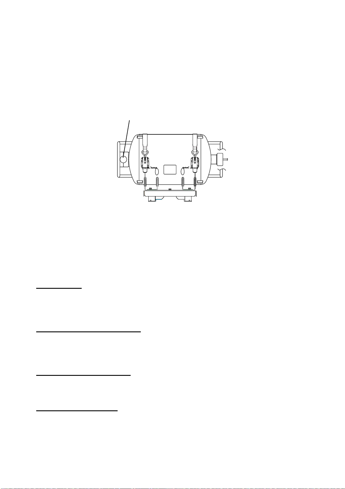
Data Recording Unit
The Data Recording Unit is housed in a highly visible protective capsule which can withstand a
fire of 1100°C for 1 hour and deep-sea pressure of 6000 m.
The underwater acoustic beacon (pinger) on the capsule automatically transmits 10 ms pulses at
37.5 kHz for at least 30 days when it is submerged in water. The expected life of the beacon is 6
years. The DRU is connected to the Data Collecting Unit (DCU) with a non-halogen FireWire
cable (IEEE1394).
Underwater Acoustic Beacon
Data Recording Unit
Integrity
The recording integrity is ensured by continuous monitoring of power supply, record function, bit
error rate, and microphone functionality. Visual alarm is generated for malfunction of any of these.
Alarm status is also indicated by relay contacts.
Data items to be recorded
Date and time
Date and time are obtained from an external GPS navigator referenced to UTC. Time information
is recorded at intervals of 1 s. Without date and time data, no data except audio signal is
recorded.
Ship’s position and datum used
Latitude, longitude and datum are obtained from a GPS navigator, Loran-C receiver or other
EPFS or INS available on standard digital interface. The source of data is identifiable on
playback.
Speed (water and/or ground)
Speed through the water (STW) or speed over the ground (SOG) is recorded at intervals of 1 s.
The resolution is 0.1 kt. Transverse speed is also indicated when available on board.
Heading (true, magnetic)
Heading is recorded at intervals of 1 s to a resolution of 0.1°. The data is labeled G
(gyrocompass), GPS, GLONASS, MAG. If heading information is not available in IEC 61162
format, an appropriate interface may be necessary.
3
Page 14

AIS-VHF data-link message, AIS-VHF data-link own-vessel message
Where there is no commercial off-the-shelf interface available to obtain radar data then AIS target
data shall be recorded as a source of information regarding other ships, otherwise AIS
information may be recorded additionally as a beneficial secondary source of information on both
other and own ship.
The VDM message (UAIS VHF Data-link) shall be recorded in such a way that all target data
available from the onboard AIS are acquired. If the VDO message (UAIS VHF Data-link
Own-vessel report) is recorded, this shall be additional to the recording of individual sensor data.
Depth (echo sounder)
Depth under keel up to a resolution of 0.1 m as available on the ship is recorded.
Alarms
The status of all IMO mandatory alarms is recorded individually with ID number and time stamp.
Audible alarms from the alarm units are stored simultaneously by the bridge audio microphones.
Rudder order/response
Rudder order and response angles are recorded up to a resolution of 1° as available on the ship.
The rudder information is recorded. If more than one rudder is provided, the circuitry can be
duplicated.
Engine order/response
The DCU obtains the engine order and response from the engine telegraph or direct engine
control. The signal level is normally 0-10 V. The engine parameters with shaft revolution and
ahead/astern indicators are recorded to a resolution of 1 rpm.
All order and response from bow, stern, thruster, tunnel thrusters and controllable pitch propellers
shall be recorded. The S-VDR shall record this data if said serial data is available.
Hull openings, watertight doors
Inputs digital or RS-422 serial can be connected individually. The data is received at intervals of 1
s and stored with time stamps. Serial data sentence XDR is received at a data rate of 1,200-9,600
baud.
Accelerations and hull stresses
The DCU obtains signals from appropriate hull stress and response monitoring devices. The
inputs are recorded individually and stored with time stamps. Serial data sentence XDR is
received at a data rate of 1,200-9,600 baud.
Wind speed and direction
The DCU obtains the signal from appropriate wind speed and direction sensor. The inputs are
recorded individually and stored with time stamps. Serial data sentence XDR is received at a data
rate of 1,200-9,600 baud.
VDR alarm output
There is no requirement for the S-VDR to send alarm messages. If, as an option, such messages
are sent then the appropriate sentence format is ALR.
4
Page 15

Radar data
Radar image including range rings, EBLs, VRMs, plotting symbols, radar maps, parts of SENC,
voyage plan, and other essential navigational indications, is recorded in the DRU via the interface
in the DCU which is connected to the buffered video output of the radar display unit. One
complete picture frame is captured at intervals of 15 s.
The radar display complying with IEC 60936-1 should have a buffered output (VESA DMTS
compatible) with resolutions between 640 x 480 and 1280 x 1024, and can be directly connected
with the VDR. Scanning may be interlaced or non-interlaced.
Bridge audio
Up to six microphones are supplied as standard to record conversation at conning station, radar
display and chart table. If possible, the microphones should be positioned to capture the audio
from the intercom, public address system, and audible alarms on the bridge. The microphones
are labeled Mic1, Mic2, etc. Microphone captures conversation in the bridge, audio signals from
equipment and sound from machinery. The microphone generates a test beep every 12 hours
which is also recorded. The microphone picks up audio signals ranging from 150 to 6000 Hz.
Communications audio
A maximum of two VHF communications are recorded for both transmitted and received audio
signals. The VHF radio connections are labeled VHF1 and VHF2.
5
Page 16

1.2 Operating Procedure
The VDR comes with a key to lock the DCU to protect against any unauthorized access. The key
must be kept securely after installation.
1.2.1 Powering, recording
On the power control panel in the DCU, turn on the AC SUPPLY MAINS, DC SUPPLY MAINS and
BATTERY BACK-UP switches in this order. Confirm that the NORMAL LED on the power control
panel and RAP lights. The VDR records data automatically in the DRU and backup HDD.
NORMAL LED
REMOTE ALARM PANEL
Breaker switches (from left)
Battery Backup, DC, AC
POWER CONTROL PANEL
NORMAL LED
1.2.2 Stopping recording
Recording is terminated only under the following conditions:
- During essential maintenance purposes while the vessel is in port.
- When the vessel is laid-up.
To stop recording, turn off the BATTERY BACKUP, DC SUPPLY MAINS and AC SUPPLY MAINS
switches in this order. DO NOT turn off the system by the main breaker while the BATTERY
BACKUP switch is on. If this is done, the system operates on the batteries. The system stops
after running on batteries after 2 hours.
6
Page 17

1.3 Operation on Remote Alarm Panel
No power switch is provided on the Remote Alarm Panel; it is turned on and off by the power
switch on the DCU. When the ERROR LED (red) on the Remote Alarm Panel is on, identify the
error by checking code number in the error code tables in Chapter 3. The buttons on the Remote
Alarm Panel work as described in the figure below.
Buzzer
DIMMER:
Adjust panel backlighting;
Setting range: 0 - 10
Default: 8 (Just after
power on)
At setting 0: ERROR
LED lights at level 1.
Other LEDs are off.
Display software version
no. (pressed together).
TEST: Tests LCD.
ACK: Silences buzzer.
SAVE: Stops recording onto current memory area in the backup
HDD and starts recording onto another menory area.
Status Display
--X: Indicates that X no. of recording
areas exist. (X: 4, 3, 2, 1)
---: Recording area is not yet known.
(at startup or when recognizing HDD)
LEDs (from left)
SAVE (yellow):
Starts blinking from OFF
state when recording is
stopped, then lights
steadily.
If the HDD is disconnected,
this LED lights also.
NORMAL (Green):
On at normal operation.
ERROR (red):
Lights for error.
Note: The buzzer sounds every time the radar connected to the VDR is turned off. Press the
ACK button to silence the alarm.
NOTICE
After pressing the SAVE button four times, data
will not be recorded. Replace the HDD with an
initialized one, or contact a FURUNO agent for
ecessary procedure.
SAVE button
If you press the SAVE button, the current memory area in the backup HDD stops recording and
another area starts recording. If an incident occurs, press this button immediately. If another
incident occurs, press the button again. The memory in the backup HDD is divided into four areas.
When you press the SAVE button, the number of recording area in the HDD is reduced by one.
After saving is completed, the buzzer sounds intermittently for 10 seconds. However, if an alarm
is violated during the saving, the alarm buzzer has priority. If you press the SAVE button four
times, all four areas stop recording. To remove the HDD, see paragraph 1.4.
If you pressed the SAVE button during an incident, consult a FURUNO dealer to restore the HDD
after the authorities complete an investigation of the incident.
7
Page 18

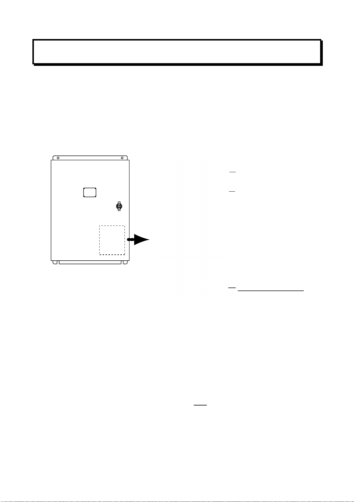
1.4 Removing HDD at an Incident
VDR information is copied automatically into the backup hard disk drive (HDD) for more than 12
hours (max. 13 hours) and is then automatically written over with new data. Bring the HDD with
you after an incident if possible. Press the SAVE button only when an incident occurs. To replace
the HDD under other circumstances, see section 2.6.
To remove the HDD, do the following:
1. Press the SAVE button (long press) on the RAP (Remote Alarm Panel). The yellow LED starts
blinking, showing that recording is being terminated.
2. Wait until the LED lights steadily. If the LED does not light, press the SAVE button
consecutively until the LED lights.
Note: Turning off the power is not required at an incident. However, to replace the HDD, turn
off the power after the step 2.
3. Pull the knob on the HDD holder to open the holder.
4. Disconnect the IEEE1394 cable.
5. Remove the HDD.
Knob
DCU, showing location of HDD
1.5 How to Release DRU
To remove the DRU from the bracket (cradle)
do the following:
1. Loosen the hand-tightened cap.
2. Pull the DRU cable straight out.
(The cable may be cut after an incident.)
3. Remove two snap pins and then two hinge
pins.
4. Lift the release levers.
HD
3. Hinge pin
HDD
IEEE1394
Cable
4. Release levers.
1. Cap
2. DRU cable
3. Snap pin
8
Page 19

2. MAINTENANCE
Periodic checks and maintenance are important for proper operation of any electronic systems.
This chapter contains maintenance instructions to be followed to obtain optimum performance
and the longest possible life of the equipment. Any maintenance must be executed by a suitably
qualified technician.
WARNING
ELECTRICAL SHOCK HAZARD
Do not open the equipment.
Only qualified personnel
should work inside the
equipment.
Do not disassemble or modify the
equipment.
Fire, electrical shock or serious injury can
result.
2.1 Annual Recertification
The VDR must undergo an annual performance test to recertify suitability. This test is conducted
by a test engineer authorized by the manufacturer and certified by a relevant ship classification
society, the content and procedure of the test in accordance with the regulations of that society.
For further details about the VDR performance test, contact your ship classification society.
2.2 Cleaning
Dirt or dust may be removed from units with a soft cloth.
Fresh water-moistened cloth may be used to remove
stubborn dirt. DO NOT use any commercial cleaning
agents to clean any unit. They can remove paint and
markings. This is especially important with the
Waterproof Microphone VR-3012W. The watertight
integrity of the microphone will be compromised if any
commercial cleaning agent contacts the ventilation
sheet behind the MIC cover.
MIC COVER
Waterproof microphone VR-3012W (bulkhead type)
9
Page 20

2.3 Software Maintenance
2.3.1 Software list
The software and software version of the VR-3000/VR-3000S are as shown in the table below.
VR-3000/VR-3000S software list
Software name Software version Date
VR-3000 System Program 2450031-02 July 2008
VR-3000 RAP 2450026-01 Mar 2006
2.3.2 Checking software version of system program
Follow the procedure below to check software version of system program.
1. Start up a PC that uses Windows XP or Windows 2000 OS.
2. Change the IP address to 10.0.0.102 and the subnet address to 255.0.0.0.
3. Connect the cross LAN cable (supplied) between the LAN port on the PC and J14 (Data) in
the DCU of the VR-3000/VR-3000S.
4. Start up the VDR Maintenance Viewer from the PC.
5. Open the menu of this program from Maintenance/VDR Config Management. The VDR
Config Management screen appears.
6. Click the Download button on the screen.
7. Click the software tab to change the screen. The program version is displayed at the right side
of the VDR system program.
2.3.3 Checking software version of RAP
Push and hold down the RAP’s plus and minus buttons together. A three-digit number appears
(for example, “101”) and these digits are the version number.
10
Page 21

S
ry
2.4 Replacing Batteries
Every four years, the back-up batteries (2 pcs.) in the DCU must be replaced with new ones
(Type: OP24-12 Code no.: 004-385-010) by a qualified service engineer. Note that the batteries
should be recycled. Contact a FURUNO dealer for further details.
Observe the following precautions with the batteries:
WARNING
Battery handing precautions
- Do not attempt to dismantle the battery. If
accidental skin/eye contact is made with
the battery fluid, wash the affected
area/part immediately with liberal amounts
of clean fresh water and seek IMMEDIATE
medical attention.
- DO NOT INCINERATE batteries as they
are liable to rupture if placed into a fire.
Batteries that have reached the end of
their service life must be disposed of in
accordance with appropriate regulations.
- Do not short battery terminals. Short can
lead to bursting or fire.
Do not:
- use batteries of different capacities
- mix old batteries with new
- mix batteries of different makes
Batteries themselves may become
damaged or damage to electrical
parts may result.
CAUTION
To replace the batteries, do the
following:
1. Open the DCU door with its key.
2. Power off the DCU.
Battery
Battery leads
(under vinyl boot)
Batte
3. Unfasten J3 connector from the
PDU Board (24P0083)
4. Unfasten two screws securing the
batteries.
crew
Screw
J3
5. Disconnect four battery leads,
which are covered with the “vinyl
boots”.
6. Use the handle to remove
batteries from the DCU.
7. Replace batteries.
8. Lock the DCU.
DCU, inside view
11
Page 22

2.5 Replacing Acoustic Beacon
The life of the underwater acoustic beacon is approximately 6 years. It must be replaced (Type:
DK-120, Code no. 000-148-648) by a qualified service technician before validity date marked on
the beacon.
1. Unfasten two bolts and remove the beacon cover.
2. Use box screwdriver (7 mm) or slotted screwdriver to unfasten four bolts and then remove
the beacon.
3. Attach a new beacon.
Bolts
Water switch is right side.
(The label is upside-down.)
Validity date should face in front.
Acoustic beacon
DRU (Beacon cover removed)
NOTICE: As the acoustic beacon contains a battery, it must be disposed of in accordance with
appropriate regulations.
12
Page 23

4
Knob
2.6 Replacing Backup HDD
On some vessels several backup HDDs (Type: VR-3011, Code No.:004-385-000, Option) are
carried onboard, replacing one when it is necessary to transport it from the vessel for playback
and extract.
A backup HDD may only be replaced in the follow situations:
1) When the equipment can be powered off; for example, maintenance while in port, etc.
2) An incident has occurred and the Save button on the RAP (VR-3016) was operated to stop
recording.
An HDD may not be re-used for recording after the Save button has been operated four times.
Contact a FURUNO dealer for further details.
A backup HDD records navigation data for more than past 12 hours (13 hours max). For longer
recording, use Live Player Backup.
DCU
VR-3010
HDD
VR-3011
DRU
VR-5020
RAP
VR-3016
Replacing backup HDD
1. Open the DCU with its key. Turn off the
DCU.
2. Pull the knob on the HDD holder to open
the holder.
3. Disconnect IEEE1394 cable from the HDD.
Remove the HDD.
4. Set new HDD to holder.
5. Connect IEEE1394 cable.
6. Push knob on the HDD holder to close the
holder. Turn on the DCU.
7. Confirm that HDD is operating (DCU power
is ON, Save LED is OFF) with no error.
8. Close the DCU and lock it with its key.
9. Refer to the operator’s manual of the Live
Player
Pro for how to playback/extract recorded
data from the Backup HDD.
Change
AC Adapter
HDD
VR-3011
IEEE1394
(4Pin – 6Pin)
PC for
Playback / Extract
HD
HDD
IEEE139
Cable
13
Page 24

2.7 Replacing Fuses
The battery cable in the DCU contains two 10A fuses in fuse holders. If a fuse blows, the
BACKUP BATTERY LED may not be lighting. Find the cause before replacing a fuse. Have a
serviceman replace any fuse.
Fuses
2.8 Replacing Parts
Interval-specific parts
The batteries in DCU and the acoustic beacon on the DRU must be replaced every 4 and 6 years
respectively to comply with IMO conventions. Record the date of expiration on the card in the
card holder on the door of the DCU.
Part Replacement
interval
Battery in DCU 4 years 2 pcs., replace together
Acoustic underwater beacon in DRU 6 years
Consumable parts
Remarks
The parts in the table below should be replaced before the estimated lifetime shown. The period
of expiration begins from the date of installation. Record the date of replacement on the card in
the card holder on the door of the DCU.
Consumable part Life Remarks
Backup HDD 2 years / 25℃ Data cannot be recorded to the backup HDD
when it fails. Error 018 is generated when
this occurs.
DC-DC converter 4 years / 25℃* If DC power supply fails, RAP indicates 082
and AP in DCU indicates 84.
DCU chassis fan 6 years / 25℃*
DCU CPU fan 6 years / 25℃*
CMOS battery on CPU board
in DCU
AC power supply 6 years / 25℃ If AC power supply fails, RAP indicates 214
* = Product has a 90% probability of achieving full lifespan
6 years / 25℃ Failure of this battery prevents GPS time
Failure of one or both of these fans prevents
the CPU from operating, which may prevent
start up of the VDR.
synchronization. Error 026 is generated
when this occurs.
with AC power switch ON.
14
Page 25

2.9 Verifying Recording Function of the DRU
Verify the DRU’s recording function at the annual inspection and when repairing or maintaining the
VDR or sensors connected to the VDR. The verification requires the Live Player V4. Refer to its
Operator's Manual for the operating procedure. Note that data cannot be extracted during recording.
1 Set the Playback/CPU switch in the DCU to the Playback position.
2. Wait about 1
3 Connect the PC to DCU as shown in the Figure below.
0 minutes and verify that Alarm 174 occurs.
DCU
Set slide SW to Playback.
J8 (DRU)
DRU
Disconnect cable
from HDD.
PC
J6 (Playback)
IEEE1394 cable
4 Disconnect the cable attached to the Backup HDD.
5.Start the Live Player V4 on the PC.
6 Open the Too l menu and select Source Select. Select DRU from the pull-down menu.
7 Click the Analyze Track button.
8 Click the Connect button.
9. Select Extract from the Tool menu to show the Extraction dialog box.
10. Select the track to extract.
11. Click the Select button and select the location where to save data.
12. Click the Start button.
13. After the extraction is completed, click OK, Close and Close in that order. Then, do the following.
a) Disconnect the cable between the PC and J6 on the DCU.
b) Connect the Backup HDD.
c) Set the Playback/CPU slide switch in the DCU to the CPU position.
15
Page 26

2.10 Confirmation of Peripheral Devices
Confirm the data from serial signal output devices, analog signal output devices and contact signal
output devices. To do this, connect the PC to the DCU and use the Live Player software.
Serial signal output devices
The threshold levels of the time-out for serial signal input are preset. If the data is not input to the VDR,
an error code appears on the Remote Alarm Panel (see paragraph 3.2). Confirm the accuracy of the
input signal, comparing the value of the input sensor and preset value in the VDR.
Analog and contact signal output devices
Confirm the signal value and accuracy, comparing the indication of the input device and the input
value on the VDR.
16
Page 27

3. TROUBLESHOOTING
This chapter provides information on possible causes of problems you may experience with your
VDR. If you still have a problem after referring to the table, contact your local dealer or national
distributor for further advice. Always provide the product serial number.
3.1 General Troubleshooting
Use the table below to identify the trouble, cause and possible solution.
Troubleshooting table
Symptom Possible causes Possible solution
AC and/or DC LED not lit No power supply
BATTERY BACKUP LED not lit No power from the battery Call for service.
ERROR LED lighting in red Malfunction of the system
Check the breaker switches on
ship’s mains switchboard.
Restart the system. If the problem
still remains, call for service.
Check integrity of DRU
connection.
17
Page 28

3.2 Error Codes
A
Error codes may appear on the status display on the Power Control Panel to alert to possible
trouble. Below is a list of those codes.
System software: 2450031-02
Error Error Name Description
--4
--3
--2
--1
---
HDD BACKUP_HDD_MISSINGBackup HDD not connected to VDR,
Normal operation. "--X" (X:1,2,3,4)
means number of exting recording
area in the HDD. "---" is shown at
startup or when recognizing HDD.
or no memory area.
1) SAVE button pressed and backup
HDD removed: Replace backup HDD
2) Other situations: Reset VDR. If
normal operation not restored,
request service.
ction
018 Backup HDD No
Connection
022 DRU No Connection DRU has been discontinued more
026 GPS Large Time
Difference
042 Radar No Connection One of the active/enabled video
082 RAP No Connection RAP is missing. Connection to RAP
084 AP No Connection No alarm panel connection Check connection to alarm panel.
088 JB No Connection Indicates that Junction Box (No.1) is
This indicates that the BACKUP has
been disconnected more than 120
seconds.
than 120 seconds.
This indicates that the time difference
between system time and time
supplied by UTC source is more than
the specified time.
channels can’t grab from the
channel. This can be either because
radar is turned OFF or wrong
configuration.
is lost.
missing.
Connect BACKUP HDD or
investigate LOG and repair/replace.
Connect DRU again or investigate
LOG and repair or replace.
Restart VR-3000/S. Try to see if the
CMOS clock is set correctly. If not,
set it and restart VR-3000/S. If yes,
find out why the time source device
GPS is delivering "out of bands" time
info.
If radar is turned OFF, press ACK on
the RAP to silence alarm. Turn on
radar. If no error appears, the system
is normal. If the error appears, check
cable connections or setting.
Check cable connected to RAP.
Reconnect RAP.
Check cable and IP-address setting.
094 Backup HDD Recording
Fail
098 DRU Recording Fail Indicates that DRU is inactive-not
170 VDR Configuration Fail Data can not be stored because VDR
171 VDR Recording Buffer
Overflow
173 Fatal System Failure
174
IEEE1394 Bus Recover
Giveup
Indicates that Backup is inactive-not
storing data.
storing data.
setting data is corrupted.
Radar video inputs over the capacity
of the recording buffer memory.
Fatal system error. VR-3000/S
rebooted automatically after an error
occurred.
Cannot Recover DRU and Backup
HDD.
Check connection to Backup HDD. If
not still storing, request service.
Check connection to DRU. If not still
restarting recording, request service.
Restore VDR settings data. If not,
request service.
Check or reduce the radar channels
or video resolusion.
If VR-3000/S repeat continuously,
request service
Restart VDR. If VR-3000/S does not
recover, request service
(Continued on next page)
18
Page 29

Error codes (con’t from previous page)
Error Error Name Description Action
186 DRU Memory Shortage It looks that data cannot be recorded
more than 12 hours.
Modify radar recording setting. Max.
recordable channel: two channels.
214 Battery Running Both AC and DC power are down and
switching to battery drive. Audible
alarms are generated for max. two
218 MIC Test Fail This ALARM is issued when the
microphone test fails. This test can
be run from Audio tab in the VDR
Maintenance Viewer, and is run every
12-hours during normal operation.
226 DRU Flash Device No
match
234 GPS No Connection System does not receive UTC
246 PDU No Connection Cable connection inside DCU is
254 Self Test Fail System failed by the self test. Request service.
3xx
(301-372)
401 Battery No Connection
402 Terminal Board No
403 Battery Voltage Low Batter voltage is lowered. It is required replacement of battery.
Serial No Connection Data is not delivered from a serial
or Battery Voltage Low
Connection
This indicates that no. of FLASH
devices found in DRU and defined in
CONFIGURATION is not same.
information.
faulty.
ohannel within an assigned time.
Battery voltage is not coming or it is
low.
Terminal board is abnormal. Confirm cable connection between
Reconnect AC and/or DC power.
Check MIC TEST in the VDR
Maintenance Viewer. If this is OK,
locate the faulty microphone and
check/replace it.
Check if no. of FLASH devices and
configuration setting are same.
Check that a valid UTC source is
connected to the serial port defined
as UTC source.
Check cable between PDU and CPU
block in DCU.
Reconnect serial data. Check failed
device.
Confirm that the battery switch is
turned on. If ok, battery is required to
replace a new one.
terminal board and audible interface
board.
406 DRU Exchanged This indicates that DRU is replaced. Restart VR-3000/S
407 Backup HDD Exchanged This indicated that backup HDD is
replaced.
411 Frame Grabber Board
Fail
412 Audio Board Fail Audible interface board is available
413 Serial Board Fail Serial interface board is available but
42x
(422-428)
431
432 JB Buffer overflow
JB No Connection Poor connection between JB(No.2-
DCU Serial Buffer
overflow
Radar interface board is available but
it is not recognized.
but it is not recognized.
it is not recognized.
8)and DCU.
Serial data from DCU serial channels
(1-8) aren't recorded to DRU and
Backup HDD correctly.
Serial, analog and digital data from
Junction Box aren't recorded to DRU
and Backup HDD correctly.
Restart VR-3000/S
Request service.
Request service.
Request service.
Check cable and IP-address setting.
Restart VDR. If error occurs again,
request service.
Restart VDR. If error occurs again,
request service.
19
Page 30

3.3 Testing Display of Remote Alarm Panel
Press the TEST button on the RAP to check that all LCD segments are displayed properly.
20
Page 31

4. LOCATION OF PARTS
4.1 Parts Location
4.1.1 Data Collecting Unit (VR-3010)
Fuses
From top:
1) RADAR I/F
Board (RI-3010)
2) AUDIO Board
3) SERIAL Board
4) Riser Card
(24P0068)
5) CPU Board
Compact Flash
Card
CONNECTOR
PANEL board
(24P0081)
Power Supply
(RTW28-11RN-1)
(underneath)
DC-DC
Converter
(ACE-716C-RS)
(underneath)
Battery
(OP24-12)
(2 pcs.)
Backup Hard Disk (HDD)
(VR-3011)
PDU Board
(24P0083)
AP PANEL Board
(24P0076B)
AP MAIN Board
(24P0075B) (underneath)
LED PANEL Board
(24P0082)
Terminal Board 2
(24P0079)
Terminal Board 1
(24P0078)
(w/WAGO connectors)
Data Collecting Unit (VR-3010)
21
Page 32

4.1.2 Data Recording Unit (VR-5020-9G or VR-5020-6G)
Underwater Acoustic
Beacon (DK-120)
DRU
FLASH DISK Board
(FW-ATA2501-1)
2.5-inch FLASH DISK
(SLFLD25-8GM1U1 (for 6G) or
DK0090G88TNO (for 9G))
REPEATER
Board (24P0080)
(Firewire cable connects
to CONNECTOR Board.)
CONNECTOR Board
(24P0042)
CONNECTION Board
(24P0087)
Components inside capsule
Data Recording Unit (VR-5020-9G or VR-5020-6G)
22
Page 33

4.1.3 Junction Box (IF-8530)
MAIN Board
(24P0069)
Terminal Board
(24P0077)
(w/WAGO connectors)
Junction Box (IF-8530)
4.1.4 Remote Alarm Panel (VR-3016)
Remote Alarm Panel (VR-3016)
RAP PANEL Board
(24P0076A)
(underneath)
RAP MAIN Board
(24P0075A)
(underneath)
23
Page 34

4.2 Parts List
This equipment contains complex modules in which fault diagnosis and repair down to
component level are not practical (IMO A.694(17)/8.3.1. Only some discrete components are
used. FURUNO Electric Co., Ltd. believes identifying these components is of no value for
shipborne maintenance; therefore, they are not listed in this manual. Major modules can be
located on the parts location on previous pages.
Name Type Code No.
Data Collecting Unit (VR-3010)
AP MAIN Board 24P0075B 004-385-320
AP PANEL Board 24P0076B 004-385-330
AUDIO Board PCI-9111-DG 000-148-411
Battery (2 sets) OP24-12 004-385-010
Compact Flash Card CFI-128MDG(H02AA) 004-385-140
CONNECTOR PANEL Board 24P0081 004-385-110
CPU Board PEB3730VL2A 004-383-400
DC-DC Converter ACE-716C-RS 004-385-450
RADAR I/F Board RI-3010 004-388-070
LED PANEL Board 24P0082 004-385-340
PDU Board 24P0083 004-384-750
Power Supply RTW28-11RN-1 004-385-390
Riser Card 24P0068 004-385-070
SERIAL Board 99033-8 000-156-911
Terminal Board 1 24P0078 004-385-350
Terminal Board 2 24P0079 004-385-700
Backup Hard Disk (HDD) VR-3011 004-385-000
Data Recording Unit (VR-5020-9G or VR-5020-6G)
CONNECTION Board 24P0087 000-166-816-10
CONNECTOR Board 24P0042 004-381-030
SLFLD25-8GM1U1 (for 6G) 000-166-792-10 FLASH DISK
DK0090G88TNO (for 9G) 000-166-822-10
FLASH DISK Board FW-ATA-2501-1 000-161-500-11
REPEATER Board 24P0080 000-155-924-01
Underwater Acoustic Beacon DK-120 000-148-648
Junction Box (IF-8530)
MAIN Board 24P0069 004-385-490
Terminal Board 24P0077 004-385-510
Remote Alarm Panel (VR-3016)
RAP MAIN Board 24P0075A 004-385-520
RAP PANEL Board 24P0076A 004-385-560
24
Page 35

5. INTERFACE
(IEC 61162-1, IEC 61162-2)
5.1 Data Sentences
Some sentences described here are the ones proposed by the recent IEC TC80/WG6 (Digital
Interface Working Group) at the time of this publication. They are marked with PAS 101 or PAS
102.
ALA - Set detail alarm condition
0 1 2 3 4 5 6 7 8 9
$xxALA, hhmmss.ss, aa, aa, xx, xxx, A, A, c—c *hh<CR><LF>
0: Header 1:
3: Sub-system/equipment/item indicator of alarm source 4: Number of equipment / units / items
5: Number of alarm source 6: Alarm condition 7: Alarm’s acknowledge state
8: Alarm’s description text 9: Check-sum
ALR - Set alarm status (PAS 101)
Updated the text label of the alarm identification field to be the same as that field in the ACK
sentence.
$--ALR,hhmmss.ss,xxx,A,A,c--c*hh<CR><LF>
Event time (Optional) 2: System indicator of alarm source
Alarm’s description text
Alarm’s acknowledge state, A = acknowledged, V=
unacknowledged
Alarm condition (A = threshold exceeded, V = not exceeded)
Unique alarm number (identifier) at alarm source
Time of alarm condition change, UTC
25
Page 36

DOR - Door status indication
This sentence indicates the status of watertight doors, fire doors and other hull openings /
doors. Malfunction alarms of the watertight door, fire door and hull opening/door controller
should be included in the “ALA” sentence.
$xxDOR, A, hhmmss.ss, aa, aa, xxx, xxx, A, c—c, *hh<cr><lf>
0 1 2 3 4 5 6 7 8 9
0) Header
1) Message type
S: Status for section: the number of faulty and/or open doors reported in the division specified in
field 4. The section may be a whole section (one or both of the division indicators are empty) or a
sub-section. (If S is used then it shall be transmitted at regular intervals.)
E: Status for single door. (E may be used to indicate an event).
F: Fault in system: If limited to one section, indicated by division indicator fields, if not, division
indicators empty. (F may be used to indicate an event.)
2) Time stamp
Time when this status/message was valid.
3) System indicator of door status
Indicator characters as door system. The field is two fixed characters.
4) Division indicator of door allocation (1)
Indicator showing division where door is located. This field is two characters.
It may be physical fire zone or entity identifier for control and monitoring system, e.g., central number.
5) Division indicator of door allocation (2)
Indicator showing in which division the door is located. This field is three numeric characters.
It may bephysical deck number or identifier for control and monitoring system sub-system,
e.g., loop number.
6) Door number or door open count
Number showing door number or number of doors that are open/faulty.
This field is three fixed numeric characters.
7) Door status
This field includes a single character specified by the following: when S status indicated in 2nd field,
this field is ignored
O = Open
C = Close
F = Free status (for watertight door)
X = Fault (impossible to know state)
8) Message's description text
Additional and optional descriptive text/door tag. Also if a door allocation identifier is string type, it is
possible to use this field instead of above door allocation fields.
Maximum number of characters will be limited by maximum sentence length and length of other fields.
DPT - Depth
IMO Resolution A.224 (VII). Water depth relative to the transducer and offset of the measuring
transducer. Positive offset numbers provide the distance from the transducer to the waterline.
Negative offset numbers provide the distance from the transducer to the part of the keel of
interest.
$--DPT, x.x, x.x*hh<CR><LF>
Checksum
Offset from transducer, in meters = distance from transducer to water-line
Water depth relative to the transducer, in meters
26
Page 37

DTM - Datum reference (to be further developed)
Local geodetic datum to which a position location is referenced.
$--DTM, ccc, a*hh<CR><LF>
Country sub-division code
W72 - WGS 72, W84 - WGS 84,
IHO - datum code,
999 - user defined
ETL - Engine telegraph operation status
The ETL sentence indicates engine telegraph position including operating location and
sub-telegraph indicator.
$xxETL, hhmmss.ss, a, xx, xx, a, x, *hh<cr><lf>
0 1 2 3 4 5 6 7
0) Header
1) Event Time
2) Indicator of command
O = Order
A = Answerback
3) Position indication of engine telepgraph
00 = Stop engine
01 = [AH] Dead Slow
02 = [AH] Slow
03 = [AH] Half
04 = Full
05 = [AH] Nav. Full
11 = [AS] Dead Slow
12 = [AS] Slow
13 = [AS] Half
14 = [AS] Fulll
15 = [AS] Crash Astern
4) Position indication of sub telegraph
20 = S/B (Stand-by engine)
30 = F/A (Full away – Navigation full)
40 = F/E (Finish with engine)
5) Operating location indicator
B = Bridge
P = Port wing 1
S = Starboard wing 1
C = Engine control room
E = Engine side
6) Number of engine or propeller shaft
0 = single or on centre-line
Odd = starboard
Even = port
7) Checksum
27
Page 38

FIR - Fire detection (PAS 102)
0
$
>
1 2 3 4 5 6 7 8 9 10
xxFIR, A, hhmmss.ss, aa, xx, xxx, xxx, A, A, c--c, *hh<CR><LF
0: Header 1: message type 3: System indicator of fire detection 4: Division indicator of
door allocation (1) 5: Division indicator of door allocation (2) 6: Fire detector number or
activation detection number count 7. Condition 8: Alarm’s acknowledge state 9: Alarm’s
description text 10: Check-sum
GEN - Generic status information
This sentence provides a means of transmitting multi-sensor generic status information from
any source, in a format that can be registered by the VDR. The sentence is designed for
efficient use of the bandwidth and must be accompanied with a description of how to interpret
the information. Each sentence holds a base address for all status groups. Each group is
assigned a 16-bit address. Up to eight contiguous groups with increasing address may be
transmitted in a single sentence. Data is blocked in 16-bit groups. Unused bits shall be
assigned a fixed value to simplify data compression.
A separate configuration with interpretation of bit equal to "1" and "0" for all sentence groups
and bit positions that are used, must be provided as this information is not included in the
sentence. It is the responsibility of the talker to provide this information.
$xxGEN, hhhh, hhmmss.ss, hhhh[,hhhh], *hh<cr><lf>
0 1 2 3 4
0) Header
1) Address of first group in sentence
Address of first group in GEN sentence. Address is represented in hexadecimal format in range
0x0000 through 0xFFFF.
The 16-bit address is formatted as fixed 4-character HEX field.
2) Time stamp
Time when status was valid.
3) Packed generic status group
The packed generic status group is represented as a 6-bit value.
The 16-bit value is formatted as fixed 4-character HEX field.
4) Optional repeat of field 3
Optional repeated packed generic status field. Each repeat increases the status address by one.
Up to seven repetitions yielding a total of 128 status bits per sentence is possible.
hh = Check sum
28
Page 39

GNS - GNSS fix data
Fix data for single or combined satellite navigation systems (GNSS).
$--GNS,hhmmss.ss,llll.lll,a,yyyyy.yyy,a,c--c,xx,x.x,x.x,x.x,x.x,x.x*hh<CR><LF>
| | | | | | | | | | | |
| | | | | | | | | | | |
| | | | | | | | | | | +------ 10
| | | | | | | | | | +---------- 9
| | | | | | | | | +-------------- 8
| | | | | | | | +------------------ 7
| | | | | | | +---------------------- 6
| | | | | | +------------------------- 5
| | | | | +------------------------------ 4
| | | +-------+--------------------------------- 3
| +---+--------------------------------------------- 2
+------------------------------------------------------------- 1
1. UTC of position
2. Latitude, N/S
3. Longitude, E/W
4. Mode indicator
5. Total number of satllite in use,00-99
6. HDOP
7. Antenna altitude, metres, re:mean-sea-level(geoid)
8. Geoidal separation
9. Age of differential data
10. Differential reference station ID
11. Checksum
HDG - Heading Magnetic
$--HDG,x.x,x.x,a,x.x,a*hh<CR><LF>
| | | | | |
| | | | | +--------- 4
| | | +--+----------- 3
| +----+----------------- 2
+------------------------ 1
1. Magnetic sensor heading, degrees
2. Magnetic deviation, degrees E/W
3. Magnetic variation, degrees E/W
4. Checksum
HDT - Heading True
$--HDT, x.x, T*hh<CR><LF>
$--HDT,x.x,T*hh<CR><LF>
| | |
| | +--------- 2
+----+----------- 1
1. Heading, degrees true
2. Checksum
29
Page 40

HSS - Hull stress surveillance systems (PAS 102)
0
$
1 2 3 4
xxHSS, c--c, x.x, A, *hh<cr><lf>
0: Header 1: Measurement point ID 2: Measurement value
3: Data status, A = data valid, V = data invalid 4: Check-sum
Note: This must be verified by Ship Classification. VDR is required to log such data if HSS is fitted
on ship.
HTC - Heading/Track control command
$--HTC,A,x.x,a,a,a,x.x,x.x,x.x,x.x,x.x,x.x,x.x,a*hh<CR><LF>
| | | | | | | | | | | | | |
| | | | | | | | | | | | | +--- 14
| | | | | | | | | | | | +----- 13
| | | | | | | | | | | +-------- 12
| | | | | | | | | | +------------ 11
| | | | | | | | | +---------------- 10
| | | | | | | | +-------------------- 9
| | | | | | | +------------------------ 8
| | | | | | +---------------------------- 7
| | | | | +-------------------------------- 6
| | | | +----------------------------------- 5
| | | +------------------------------------- 4
| | +--------------------------------------- 3
| +------------------------------------------ 2
+--------------------------------------------- 1
1. Override, A = in use, V = not in use
2. Commanded rudder angle, degrees
3. Commanded rudder direction, L/R = port/starboard
4. Selected steering mode
5. Turn mode R = radius controlled
T = turn rate controlled
N = turn is not controlled
6. Commanded rudder limit, degrees(unsigned)
7. Commanded off-heading limit, degrees(unsigned)
8. Commanded radius of turn for heading changes, n.miles
9. Commanded rate of turn to heading changes, deg/min
10. Commanded heading-to-steer, degrees
11. Commanded off-track limit, n.miles(unsigned)
12. Commanded track, degrees
13. Heading reference in use, T/M
14. Checksum
30
Page 41

HTD - Heading/Track control data
$--HTD,A,x.x,a,a,a,x.x,x.x,x.x,x.x,x.x,x.x,x.x,a,A,A,A,x.x*hh<CR><LF>
| | | | | | | | | | | | | | | | | |
| | | | | | | | | | | | | | | | | +--- 18
| | | | | | | | | | | | | | | | +------ 17
| | | | | | | | | | | | | | | +--------- 16
| | | | | | | | | | | | | | +----------- 15
| | | | | | | | | | | | | +------------- 14
| | | | | | | | | | | | +--------------- 13
| | | | | | | | | | | +------------------ 12
| | | | | | | | | | +---------------------- 11
| | | | | | | | | +-------------------------- 10
| | | | | | | | +------------------------------ 9
| | | | | | | +---------------------------------- 8
| | | | | | +-------------------------------------- 7
| | | | | +------------------------------------------ 6
| | | | +--------------------------------------------- 5
| | | +----------------------------------------------- 4
| | +------------------------------------------------- 3
| +---------------------------------------------------- 2
+------------------------------------------------------- 1
1. Override, A = in use, V = not in use
2. Commanded rudder angle, degrees
3. Commanded rudder direction, L/R = port/starboard
4. Selected steering mode
5. Turn mode R = radius controlled
T = turn rate controlled
N = turn is not controlled
6. Commanded rudder limit, degrees(unsigned)
7. Commanded off-heading limit, degrees(unsigned)
8. Commanded radius of turn for heading changes, n.miles
9. Commanded rate of turn to heading changes, deg/min
10. Commanded heading-to-steer, degrees
11. Commanded off-track limit, n.miles(unsigned)
12. Commanded track, degrees
13. Heading reference in use, T/M
14. Rudder status A = within limits, V = limit reached or exceeded
15. Off-heading status A = within limits, V = limit reached or exceeded
16. Off-track status A = within limits, V = limit reached or exceeded
17. Vessel heading, degrees
18. Checksum
31
Page 42

MWV - Wind speed and angle (PAS 102)
When the reference field is set to relative, data is provided giving the wind angle in relation to the
vessel’s heading and wind speed, both relative to the moving vessel.
When the reference field is set to true, data is provided giving the wind angle relative to the
vessel’s heading and wind speed, both with reference to the moving water. True wind is the
vector sum of the relative apparent wind vector and the vessel’s velocity vector along the heading
line of the vessel. If represents the wind at the vessel if it were stationary relative to the water and
heading in the same direction.
$--MWV,x.x,a,x.x,a,A*hh<CR><LF>
| | | | | |
| | | | | +--------- 6
| | | | +----------- 5
| | | +------------- 4
| | +---------------- 3
| +------------------- 2
+---------------------- 1
1. Wind angle, 0 to 359 (degrees)
2. Reference, R=relative, T=true
3. Wind speed
4. Wind speed units, K/M/N
5. Status, A=data valid, V=data invalid
6. Checksum
PRC - Propulsion remote control status
This sentence indicates the engine control status (engine order) on a M/E remote control
system. This provides the detail data not available from the engine telegraph.
$xxPRC, x.x, A, x.x, A, x.x, A, x, *hh<cr><lf>
0 1 2 3 4 5 6 7 8
0) Header
1) Lever demand position
-100 - 0 - 100% from "full astern" (crash astern) to "full ahead" (navigation full) "stop engine"
2) Data status
A = data valid
V = data invalid
3) RPM demand
4) Data status
R = relative (%): 0-100% from zero to maximum rpm
T = true (rpm): "-"Astern
V = data invalid
5) Pitch demand
6) Data status
R = relative (%): -100 - 0 - 100% from "full astern" (crash astern) to "full ahead" (navigation full) "stop engine"
T = true (degree): "-"Astern
V = data invalid
7) Number egine or propeller shaft
0 = single or on centre-line
Odd = starboard
Even = port
8) Checksum
32
Page 43

RPM - Revolutions (PAS 102)
Shaft or engine revolution rate and propeller pitch.
$--RPM, a, x, x.x, x.x, A*hh<CR><LF>
Status: A = data valid
Propeller pitch, % of maximum, “-” = astern
Speed, revolutions/min, “-” = count er-clockwise
Engine of shaft number, numbered from center-line
Odd = starboard, even = port, 0 = single or no center-line
Source, shaft/engine S/E
RSA - Rudder sensor angle
$--RSA, x.x, A, x.x, A*hh<CR><LF>
Port rudder sensor ( s ee note), Status: A = data valid
Starboard (or single) rudder sensor (see note), Status: A = data valid
NOTE - Relative measurement of rudder angle without units, “-” = turn to port. Sensor output is
proportional to rudder angle but not necessarily 1 : 1.
TRC - Thruster control data
This sentence provides the control data for thruster devices
$xxTRC, x, x.x, A, x.x, A, x.x, *hh<cr><lf>
0 1 2 3 4 5 6 7
0) Header
1) Number of thrusters
Odd = Bow thruster
Even = Stern thruster
2) RPM demand
3) Data status
R = relative (%): 0-100% from zero to maximum rpm
T = true (deg) V = data invalid
4) Pitch demand value
"-" port
5) Data status
R = relative (%)
T = True (deg)
V = Data invalid
6) Azimuth demand
Direction of thrust in degrees (0 deg - 360 deg)
for thrusters capable of rotating direction of thrust
7) Checksum
33
Page 44

TRD - Thruster response data
This sentence provides the response data for thruster devices.
$xxTRD, x, x.x, A, x.x, A, x.x, *hh<cr><lf>
0 1 2 3 4 5 6 7
0) Header
1) Number of thrusters
Odd = Bow thruster
Even = Stern thruster
2) RPM demand
3) Data status
R = relative (%): 0-100% from zero to maximum rpm
T = true (deg) V = data invalid
4) Pitch response value
"-" port
5) Data status
R = relative (%)
T = True (deg)
V = Data invalid
6) Azimuth demand
Direction of thrust in degrees (0 deg - 360 deg)
for thrusters capable of rotating direction of thrust
7) Checksum
VBW - Dual ground/water speed: This sentence to be expanded as shown below:
$--VBW,x.x,x.x,A,x.x,x.x,A,x.x,A,x.x,A*hh<CR><LF>
| | | | | | | | | | |
| | | | | | | | | | +--- 11
| | | | | | | | | +----- 10
| | | | | | | | +-------- 9
| | | | | | | +----------- 8
| | | | | | +-------------- 7
| | | | | +----------------- 6
| | | | +-------------------- 5
| | | +------------------------ 4
| | +--------------------------- 3
| +------------------------------ 2
+---------------------------------- 1
1. Longitudial water speed, knots
2. Transverse water speed, knots
3. Status: water speed, A=data valid V=data invalid
4. Longitudial ground speed, knots
5. Transverse ground speed, knots
6. Status: ground speed, A=data valid V=data invalid
7. Stern transverse water speed, knots
8. Status: stern water speed, A=data valid V=data invalid
9. Stern transverse ground speed, knots
10. Status: stern ground speed, A=data valid V=data invalid
11. Checksum
34
Page 45

VDM - UAIS VHF Data-link Message (IEC 61162-2, for AIS)
!--VDM,x,x,x,x,s--s,x*hh<CR><LF>
| | | | | | |
| | | | | | +--- 7
| | | | | +----- 6
| | | | +-------- 5
| | | +------------ 4
| | +-------------- 3
| +---------------- 2
+------------------ 1
1. Total number of sentences needed to transfer the message, 1 to 9
2. Message sentence number, 1 to 9
3. Sequential message identifier, 0 to 9
4. AIS channel Number
5. Encapsulated ITU-R M.1371 radio message
6. Number of fill-bits, 0 to 5
7. Checksum
VDO - UAIS VHF Data-link Own-vessel report (IEC 61162-2, for AIS)
!--VDO,x,x,x,x,s--s,x*hh<CR><LF>
| | | | | | |
| | | | | | +--- 7
| | | | | +----- 6
| | | | +-------- 5
| | | +------------ 4
| | +-------------- 3
| +---------------- 2
+------------------ 1
1. Total number of sentences needed to transfer the message, 1 to 9
2. Message sentence number, 1 to 9
3. Sequential message identifier, 0 to 9
4. AIS channel Number
5. Encapsulated ITU-R M.1371 radio message
6. Number of fill-bits, 0 to 5
7. Checksum
35
Page 46

WAT - Water level detection (PAS 102)
This sentence provides detection status of water leakage and bilge water level, with monitoring
location data. Malfunction alarm of the water level detector should be included in the “ALA”
sentence.
$xxWAT, A, hhmmss.ss, aa, aa, xx, xxx, A, c—c, *hh<cr><lf>
0 1 2 3 4 5 6 7 8 9
0) Header
1) Message type
S: Status for section: Number of faulty and activated condition reported as number in field 4.
The section may be a whole section (one or both of the division indicators are empty) or a
sub-section. (If S is used then it shall be transmitted at regular intervals)
E: Status for each water level detector. (E may be used to indicate an event.)
F: Fault in system: If limited to one section, indicated by division indicator fields, if not, division
indicators [empty]. (F may be used to indicate an event).
2) Time stamp
Time when this status/message was valid.
3) System indicator of alarm source
Indicator characters showing system detecting water level. The field is two characters.
4) Location (1)
Indicator characters showing detection location. The field is two characters.
5) Location (2)
Indicator characters showing detection location. The field is two characters.
6) Number of detection point or detection point number
Number showing high-water-level detecting point or the number of the water leakage
detection point. This field is three fixed numeric characters.
7) Alarm condition
This field is a single character specified by the following:
N = normal state
H = alarm state (threshold exceeded)
J = alarm state (extreme threshold exceeded)
L = alarm state (Low threshold exceeded i.e. not reached)
K = alarm state(extreme low threshold exceeded i.e. not reached)
X = Fault (state unknown)
When S status indicated in 2nd field, this field is ignored
8) Descriptive text
Additional and optional descriptive text/level detector tag.
9) Checksum
36
Page 47

XDR - Transducer measurements
Measurement data from transducers that measure physical quantities such as temperature, force,
pressure, frequency, angular or linear displacement, etc. Data from a variable number of
transducers measuring the same of different quantities can be mixed in the same sentence. This
sentence is designed for use by integrated systems as well as transducers that may be
connected in a “chain” where each transducer receives the sentence as an input and adds its own
data fields on before retransmitting the sentence.
$--XDR, a, x.x, a, c--c, ........ a, x.x, a, c--c*hh<CR><LF>
Transducer “n” (see note 1)
Data, variable number of transducers
Transducer No. 1 ID
Units of measure, transducer No. 1 (see note 2)
Measurement data, transducer No. 1
Transducer type, transducer No. 1 (see note 2)
NOTES
1 Sets of the four fields “type-data-units-ID” are allowed for an undefined number of transducers.
Up to “n” transducers may be included within the limits of allowed sentence length, null fields are
not required except where portions of the “type-data-units-ID” combination are not available.
ZDA - Time and date
$--ZDA,hhmmss.ss,xx,xx,xxxx,xx,xx*hh<CR><LF>
| | | | | | |
| | | | | | +--------- 7
| | | | | +----------- 6
| | | | +-------------- 5
| | | +------------------ 4
| | +---------------------- 3
| +------------------------- 2
+--------------------------------- 1
1. UTC
2. Day, 01 to 31(UTC)
3. Month, 01 to 12(UTC)
4. Year(UTC)
5. Local zone hours, 00h to +-13h
6. Local zone minutes, 00 to +59
as local hours
7. Checksum
NOTE - Zone description if the number of whole hours added to local time to obtain GMT. Zone
description is negative for east longitudes.
37
Page 48

5.2 Interface Circuits
5.2.1 IEC 61162-1
Data Collecting Unit
A
B
Junction Box
A
A
B
38
Page 49

5.2.2 IEC 61162-2
Data Collecting Unit
G
B
A
Junction Box
B
A
G
39
Page 50

APPENDIX: PLAYING BACK RECORDED DATA
IMO Circulator SN Circ, 246 recommends that all VDR and S-VDR systems installed on or after 1
July 2006 be supplied with an accessible means for extracting the stored data from the VDR or
S-VDR to a laptop computer.
Manufacturers are required to provide software for extracting data, instructions for extracting data
and cables for connection between recording device and computer. FURUNO provides the
following:
• LIVE PLAYER V4 (instructions)
• LIVE PLAYER V4 CD (software)
• Cables: Firewire and LAN
Refer to the Operator’s Manual for the Live Player V4 for how to playback recorded data.
40
Page 51

FURUNO
VR-3000
SPECIFICATIONS OF VOYAGE DATA RECORDER
VR-3000
The Voyage Data Recorder (VDR) is a recording system required on certain categories of ships
from 1st July 2002 by the revised SOLAS Chapter V. VR-3000 fully complies with the IMO
Resolution A. 861 (20) and IEC 61996 testing standard.
1 GENERAL
1.1 Recording period DRU: 12 hours, Backup HDD: 12 hours x 4 recording areas
1.2 Battery backup More than two hours after loss of ship’s mains
2 DATA COLLECTING UNIT (DCU)
2.1 CPU Intel Pentium M 1.6GHz
2.2 Memory 512 M byte
2.3 Input signal Bridge audio: 6ch (775mV AC/600 ohm)
VHF audio: 2ch (775mV AC/600 ohm)
Serial (IEC61162-2): 4ch
Serial (IEC61162-1): 12ch
Radar Image: 1ch standard (4ch max, w/ option)
Analog signal: 16ch standard (48ch max, w/ option)
(-10 to +10V, 0 to +10V, 4 to 20mA)
Digital signal: 64ch standard (194ch max, w/ option)
Remote ACK input: 1ch
2.4 Output signal Ethernet 100base-TX: 2ch
System fail signal: 1ch
Local ACK signal 1ch
IEEE1394a 1ch (for data extraction)
3 DATA RECORDING UNIT (DRU)
3.1 Chassis Protective capsule
3.2 Memory capacity 6 GB or 9 GB
3.3 Shock resistance 50G x 11 ms
3.4 Penetration resistance 100mm diameter pin with 250 kg weight, dropped from 3 m height
3.5 Fire resistant 1100°C for 1 hour, 260°C for 10 hours
3.6 Submersible 6000 m (60MPa)
3.7 Acoustic beacon Replaced every 6 years, maximum depth 6000m, 30 days 37.5kHz
10ms pulse transmission
4 MICROPHONE
4.1 AGC amplifier output 775mV AC/600 ohm
SP - 1 E4437S01C
070810
Page 52

FURUNO
4.2 Frequency response Within 6 dB at 150Hz to 6 kHz
4.3 Audio coverage Cylindrical area of approx. 10 m in diameter
Distance: 2 m approx.
4.4 On-board beeper 1s in 12 hours period (built in)
5 JUNCTION BOX
5.1 Power Supply 24VDC from DCU
5.2 Interface
Serial IEC 61162-1/2: 2 ch, IEC 61162-1 (NMEA0183): 6 ch
Analog 16 ch (±10V, 4-20mA)
Digital (a/b) 64 ch
6 POWER SUPPLY
100-230 VAC: 2.0-0.9A, 1 phase, 50/60 Hz
VR-3000
24VDC: 7.5A max.
7 ENVIRONMENTAL CONDITION
7.1 Ambient temperature
Data collecting unit -15°C to +55°C
Data recording unit -25°C to +55°C
Waterproof microphone -25°C to +55°C
Others -15°C to +55°C
7.2 Relative humidity 95% at 40°C
7.3 Waterproofing
Data collecting unit IP20
Data recording unit IPX6
Junction box/ Remote alarm panel IP20
Microphone IP20
Waterproof microphone IPX6
7.4 Vibration (IEC 60945) 2 - 5 Hz and up to 13.2 Hz with an excursion of ±1 mm ±10%
(7 m/s
2
maximum acceleration at 13.2 Hz)
13.2 - 100 Hz with a constant maximum acceleration of 7 m/s
2
8 COATING COLOR
8.1 Data collecting unit N3.0 (standard)
8.2 Data recording unit Fluorescent orange (not changed)
8.3 Remote alarm panel N3.0 (not changed)
8.4 Microphone 2.5GY5/1.5 (not changed)
8.5 Waterproof microphone N9.5 (not changed)
8.6 Junction box N3.0 (standard)
SP - 2 E4437S01C
070810
Page 53

Page 54

 Loading...