

Page 1
Page 2
IMPORTANT NOTICES
General
• This manual has been authored with simplified grammar, to meet the needs of international users.
• The operator of this equipment must read and follow the descriptions in this manual. Wrong operation or maintenance can cancel the warranty or cause injury.
• Do not copy any part of this manual without written permission from FURUNO.
• If this manual is lost or worn, contact your dealer about replacement.
• The contents of this manual and equipment specifications can change without notice.
• The example screens (or illustrations) shown in this manual can be different from the screens you
see on your display. The screens you see depend on your system configuration and equipment
settings.
• Save this manual for future reference.
• Any modification of the equipment (including software) by persons not authorized by FURUNO will
cancel the warranty.
• The microSDXC logo is a trademark of the SD Card Association.
• Apple, App Store, iPhone, iPod, iPad are registered trademarks of Apple Inc, registered in the USA
and other countries.
• Android, Google and Google Play are registered trademarks of Google, Inc.
• FLIR is a registered trademark of FLIR Systems, Inc.
• Fusion-Link is a registered trademark of FUSION Electronics, Ltd.
• All brand and product names are trademarks, registered trademarks or service marks of their respective holders.
How to discard this product
Discard this product according to local regulations for the disposal of industrial waste. For disposal
in the USA, see the homepage of the Electronics Industries Alliance (http://www.eiae.org/) for the
correct method of disposal.
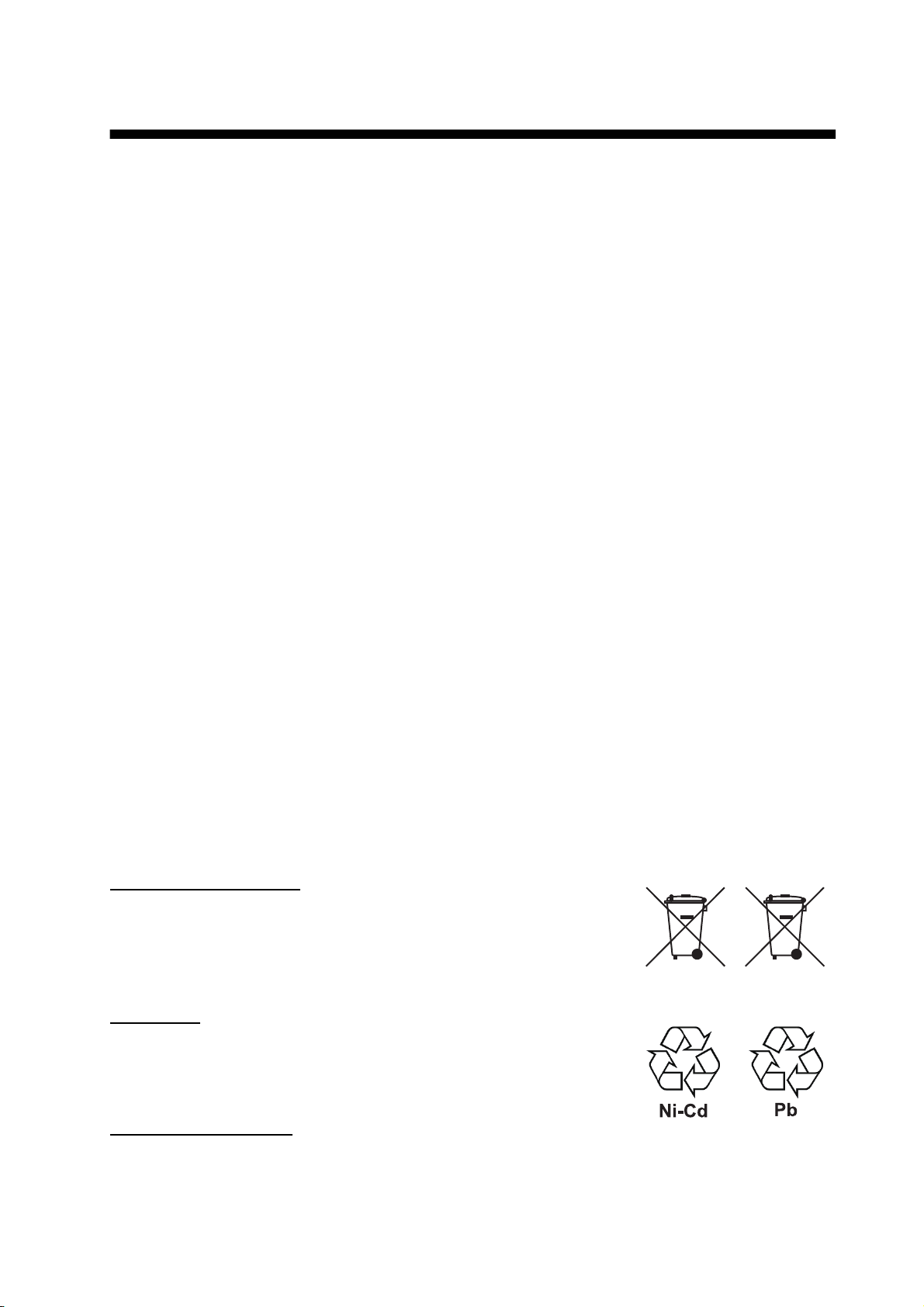
How to discard a used battery
Some FURUNO products have a battery(ies). To see if your product has a battery, see the chapter
on Maintenance. Follow the instructions below if a battery is used. Tape the + and - terminals of
battery before disposal to prevent fire, heat generation caused by short circuit.
In the European Union
The crossed-out trash can symbol indicates that all types of batteries
must not be discarded in standard trash, or at a trash site. Take the
used batteries to a battery collection site according to your national
legislation and the Batteries Directive Batteries Directive 2006/66/EU.
In the USA
The Mobius loop symbol (three chasing arrows) indicates that Ni-Cd
and lead-acid rechargeable batteries must be recycled. Take the finished batteries to a battery collection site according to local laws.
Cd
In the other countries
There are no international standards for the battery recycle symbol. The number of symbols can
increase when the other countries make their own recycle symbols in the future.
i
Page 3
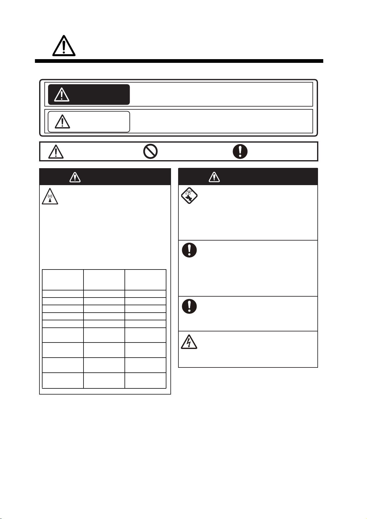
SAFETY INSTRUCTIONS
Please review these safety instructions before you operate the equipment.
Indicates a condition that can cause death or serious injury
WARNING
CAUTION
Warning, Caution Prohibitive Action Mandatory Action
if not avoided.
Indicates a condition that can cause minor or moderate
injury if not avoided.
The radar antenna emits
electromagnetic radio frequency
(RF) energy. This energy can be
dangerous to you, especially
your eyes. Do not look at the
radiator or near the antenna
when the antenna is rotating.
The distances at which RF radiation
levels of 100 W/m
exist are shown in the table.
Antenna
Model
DRS2D
DRS4A
DRS4D
DRS4DL
DRS6A
DRS12A
w/XN12A
DRS12A
w/XN13A
DRS25A
w/XN12A
DRS25A
w/XN13A
WARNING
2
and 10 W/m
Distance to
100 W/m
2
point
N/A
N/A 1.2 m
0.1 m
N/A
N/A
0.2 m
0.2 m
0.5 m
0.4 m
Distance to
10 W/m2 point
0.4 m
1.4 m
1.1 m
1.2 m
2.4 m
1.9 m
5.3 m
4.4 m
WARNING
Check that no person is near the
radar antenna before you turn on
the radar.
Serious injury or death can occur if a
person is hit by a rotating radar
antenna.
Turn off the power immediately at
2
the switchboard if water leaks into
the equipment or smoke or fire is
coming from the equipment.
Failure to turn off the equipment can
cause fire or electrical shock.
The front panel of the display unit is
made of glass. Handle it with care.
Injury can result if the glass breaks.
Do not open the equipment.
Only qualified persons can work inside
the equipment.
ii
Page 4
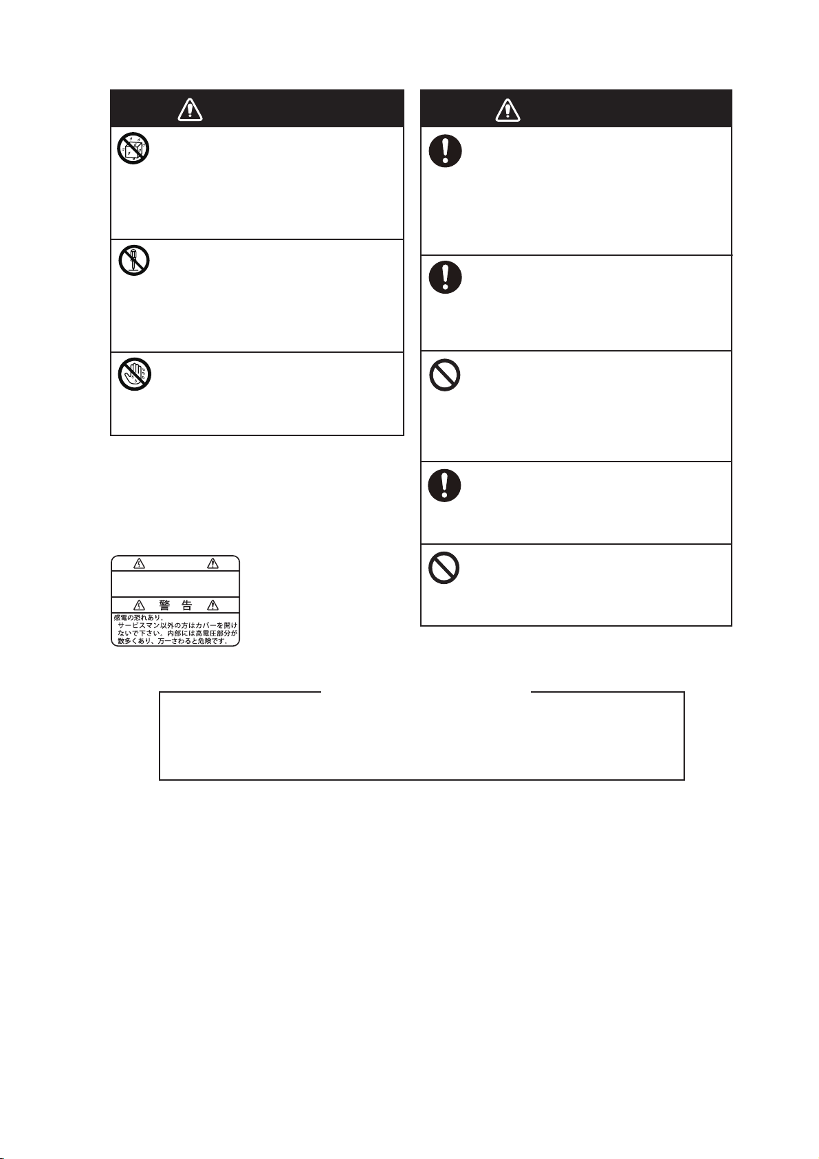
SAFETY INSTRUCTIONS
WARNING
Keep units other than the radar
antenna away from rain and
water.
Fire or electrical shock can occur if
water gets inside the equipment.
Do not disassemble or modify the
equipment.
Fire or electrical shock can occur if
the equipment is disassembled or
modified.
Do not operate the equipment with
wet hands.
Electrical shock can occur.
Safety Labels
A safety label is attached to the display unit. Do
not remove the label. If the label is missing or
damaged, contact a FURUNO agent or dealer
about replacement.
WARNING
To avoid electrical shock, do not
remove cover. No user-serviceable
parts inside.
Name: Warning Label (1)
Type: 86-003-1011-3
Code No.: 100-236-233-10
WARNING
Do not depend on one navigation
device for the navigation of the
vessel.
Always check your position against all
available aids to navigation, for the
safety of vessel and crew.
A radar is an excellent anti-collision
aid, but remember to keep watch for
possible collision conditions.
Always keep a watch while underway.
Do not leave any objects near the
radar antenna.
Fire, electrical shock or injury can
result if something gets caught in the
radar antenna.
Use the correct fuse.
A wrong fuse can cause fire or serious
damage to the equipment.
Do not maneuver the vessel based
on the depth indication alone.
Grounding can occur.
About the TFT LCD
The TFT LCD is constructed using the latest LCD techniques, and displays
99.99% of its pixels. The remaining 0.01% of the pixels may drop out or blink,
however this is not an indication of malfunction.
iii
Page 5

TABLE OF CONTENTS
FOREWORD ...................................................................................................................xi
SYSTEM CONFIGURATION ........................................................................................xiii
1. SYSTEM INTRODUCTION ................................................................................... 1-1
1.1 Controls......................................................................................................................1-2
1.2 Remote Control Unit MCU-002 (option) .....................................................................1-5
1.3 How to Turn the Power On or Off............................................................................... 1-6
1.4 How to Adjust the Brilliance of the Display and Power Switch and Hue ....................1-7
1.5 Home Screen .............................................................................................................1-8
1.6 How to Select a Display .............................................................................................1-9
1.6.1 How to select a display from the home screen ..............................................1-9
1.6.2 How to select a display from the quick page................................................ 1-10
1.7 How to Edit the Display Icons ..................................................................................1-11
1.7.1 How to add a new display icon.....................................................................1-11
1.7.2 How to edit a display icon ............................................................................ 1-12
1.8 Hidden Functions .....................................................................................................1-13
1.9 Data Area ................................................................................................................. 1-15
1.9.1 How to change the order of the data............................................................ 1-15
1.9.2 How to change the contents of a data box................................................... 1-16
1.9.3 How to add data to a data area.................................................................... 1-16
1.9.4 How to delete a data box .............................................................................1-17
1.9.5 How to switch an indication between analog (graphic) and digital............... 1-18
1.9.6 How to adjust the transparency of the data area .........................................1-18
1.10 Micro SD Cards........................................................................................................1-19
1.11 Plotter Introduction ...................................................................................................1-21
1.12 Radar Introduction.................................................................................................... 1-22
1.13 Sounder (Fish Finder) Introduction ..........................................................................1-23
1.14 Settings Menu ..........................................................................................................1-24
1.15 Function Gesture...................................................................................................... 1-27
1.16 Language .................................................................................................................1-28
1.17 Man Overboard (MOB)............................................................................................. 1-29
1.18 Wireless LAN Settings .............................................................................................1-30
1.18.1 How to connect the existing LAN .................................................................1-30
1.18.2 How to create a local wireless network ........................................................ 1-31
1.18.3 How to forget all wireless LAN .....................................................................1-31
1.18.4 Operation by wireless terminal.....................................................................1-32
2. PLOTTER .............................................................................................................. 2-1
2.1 Chart Type .................................................................................................................2-1
2.2 Display Range............................................................................................................2-2
2.3 Orientation Mode........................................................................................................ 2-3
2.4 How to Move the Chart ..............................................................................................2-3
2.5 The Boat Icon.............................................................................................................2-4
2.5.1 Description .....................................................................................................2-4
2.5.2 How to show or hide the COG vector, heading line .......................................2-4
2.5.3 COG vector length ......................................................................................... 2-5
2.5.4 Boat icon orientation ......................................................................................2-6
2.6 How to Information About a Chart Object, Chart........................................................ 2-6
2.6.1 Chart object information.................................................................................2-6
2.6.2 Chart information............................................................................................2-7
2.7 How to Find the Range and Bearing Between Two Locations...................................2-8
2.8 Multiple Plotter Displays.............................................................................................2-9
iv
Page 6

TABLE OF CONTENTS
2.9 Cartographic Text and Objects on Vector Charts.................................................... 2-10
2.9.1 Control visibility of text and object information in vector charts................... 2-10
2.9.2 Control visibility of cartographic objects in S-52 charts ............................... 2-11
2.10 Alarms ..................................................................................................................... 2-13
2.10.1 XTE alarm.................................................................................................... 2-14
2.10.2 Depth alarm ................................................................................................. 2-14
2.10.3 SST alarm.................................................................................................... 2-14
2.10.4 Speed alarm ................................................................................................ 2-15
2.10.5 Anchor watch alarm..................................................................................... 2-16
2.10.6 Other Alarm menu items.............................................................................. 2-16
2.10.7 Alarms list .................................................................................................... 2-17
2.11 Track........................................................................................................................ 2-17
2.11.1 How to start, stop recording the track.......................................................... 2-17
2.11.2 How to show or hide the track display ......................................................... 2-17
2.11.3 Track recording interval ............................................................................... 2-18
2.11.4 Track color................................................................................................... 2-18
2.11.5 Track thickness............................................................................................ 2-21
2.11.6 How to delete tracks .................................................................................... 2-21
2.11.7 How to find the number of track points used ............................................... 2-22
2.12 Plotter Menu ............................................................................................................ 2-22
2.13 NAVpilot-700 Series Auto Pilot................................................................................ 2-24
2.13.1 How to enable use of the NAVpilot.............................................................. 2-24
2.13.2 How to show the NAVpilot control box in the data area .............................. 2-24
3. 3D DISPLAY, OVERLAYS ....................................................................................3-1
3.1 3D Display ................................................................................................................. 3-1
3.1.1 How to activate the 3D display ...................................................................... 3-2
3.1.2 How to make the 3D view clearer.................................................................. 3-3
3.2 Overlays .................................................................................................................... 3-4
3.2.1 Depth shading overlay................................................................................... 3-4
3.2.2 Satellite photo overlay ................................................................................... 3-6
3.2.3 Radar overlay ................................................................................................ 3-6
3.2.4 Tide info overlay ............................................................................................ 3-8
3.2.5 Tidal current overlay.................................................................................... 3-10
4. POINTS, EVENT MARKS......................................................................................4-1
4.1 About Points, Event Marks ........................................................................................ 4-1
4.2 How to Enter a Point, Event Mark ............................................................................. 4-1
4.2.1 How to enter a point (plotter and radar displays only)................................... 4-1
4.2.2 How to enter an event mark .......................................................................... 4-2
4.3 How to Display Point, Event Mark Information .......................................................... 4-2
4.4 Event Mark Comment................................................................................................ 4-3
4.5 Default Point Settings ................................................................................................ 4-4
4.6 How to Find Number of Points Used ......................................................................... 4-5
4.7 How to Move a Point ................................................................................................. 4-5
4.7.1 How to move a point on the screen............................................................... 4-5
4.7.2 How to move a point from the points list........................................................ 4-5
4.8 How to Delete a Point................................................................................................ 4-6
4.8.1 How to delete a point on the screen.............................................................. 4-6
4.8.2 How to delete a point from the points list....................................................... 4-6
4.8.3 How to delete all points ................................................................................. 4-6
4.9 How to Edit a Point .................................................................................................... 4-7
4.9.1 How to edit a point on the screen.................................................................. 4-7
4.9.2 How to edit a point from the points list........................................................... 4-8
4.10 How to Move a Point to the Screen Center ............................................................. 4-10
4.11 How to Show or Hide All Points or Points Names ................................................... 4-10
v
Page 7

TABLE OF CONTENTS
4.12 How to Go to a Point ................................................................................................4-10
4.12.1 How to go to an on-screen point ..................................................................4-11
4.12.2 How to go to a position selected on screen .................................................4-12
4.12.3 How to go to a point selected from the points list.........................................4-13
4.12.4 How to use the NAVpilot to steer to a point .................................................4-13
4.12.5 How to display the point information for the active goto point......................4-14
4.13 How to Restart or Cancel Navigation to a Point.......................................................4-15
4.13.1 How to restart navigation to a point..............................................................4-15
4.13.2 How to cancel navigation to a point .............................................................4-15
5. ROUTES................................................................................................................ 5-1
5.1 What is a Route?........................................................................................................ 5-1
5.2 How to Create a Route............................................................................................... 5-2
5.2.1 How to create a new route from the plotter screen ........................................5-2
5.2.2 How to create a new route with points ...........................................................5-2
5.2.3 How to create a route from the points list.......................................................5-3
5.2.4 How to insert a route point on a route............................................................5-3
5.2.5 How to move a route point on a route............................................................5-4
5.2.6 How to delete a point (incl. route point) on a route ........................................5-4
5.2.7 How to remove a point from a route............................................................... 5-4
5.2.8 How to extend a route....................................................................................5-5
5.3 Routes List .................................................................................................................5-5
5.4 How to Find Number of Routes Created ....................................................................5-7
5.5 How to Find a Route on the Chart.............................................................................. 5-7
5.6 How to Delete a Route ...............................................................................................5-8
5.6.1 How to delete a route on the screen ..............................................................5-8
5.6.2 How to delete a route from the routes list ......................................................5-8
5.6.3 How to delete all routes..................................................................................5-8
5.7 How to Show or Hide All Routes ................................................................................5-8
5.8 How to Follow a Route ...............................................................................................5-9
5.8.1 How to follow an on-screen route...................................................................5-9
5.8.2 How to follow a route selected from the routes list.......................................5-10
5.8.3 How to start navigation from a route point ...................................................5-10
5.8.4 How to show the detailed information about a route....................................5-11
5.9 Operations When You Follow a Route.....................................................................5-11
5.9.1 How to restart navigation ............................................................................. 5-11
5.9.2 How to follow a route in the reverse direction ..............................................5-11
5.9.3 How to stop following a route.......................................................................5-11
5.9.4 How to skip a point on a route......................................................................5-11
5.9.5 Waypoint switching mode ............................................................................ 5-12
5.9.6 Route auto zoom.......................................................................................... 5-12
5.9.7 XTE lines...................................................................................................... 5-13
5.9.8 Waypoint arrival notification .........................................................................5-13
5.9.9 End of route notification ...............................................................................5-13
5.9.10 Steering a route with the NAVpilot ...............................................................5-14
5.10 Routes Menu............................................................................................................5-15
6. RADAR.................................................................................................................. 6-1
6.1 How to Transmit, Set the Radar in Stand-by.............................................................. 6-1
6.2 Tuning ........................................................................................................................6-1
6.3 How to Adjust the Gain ..............................................................................................6-2
6.4 How to Reduce the Sea Clutter.................................................................................. 6-3
6.5 How to Reduce the Rain Clutter................................................................................. 6-4
6.6 Range Scale............................................................................................................... 6-4
6.7 Orientation Mode........................................................................................................ 6-5
6.8 How to Measure the Range and Bearing from Your Ship to a Target........................ 6-6
vi
Page 8

TABLE OF CONTENTS
6.8.1 How to display the range rings ...................................................................... 6-6
6.8.2 How to set the number of the range rings to show........................................ 6-6
6.8.3 How to select the range rings mode.............................................................. 6-7
6.8.4 How to measure the range and bearing to an object..................................... 6-8
6.8.5 How to measure the range with the VRM...................................................... 6-8
6.8.6 How to measure the bearing with the EBL .................................................. 6-10
6.8.7 How to select the EBL reference................................................................. 6-11
6.9 How to Measure the Range and Bearing Between Two Targets ............................ 6-12
6.10 How to Off-center the Picture .................................................................................. 6-12
6.11 Heading Line ........................................................................................................... 6-13
6.12 How to Reduce Radar Interference ......................................................................... 6-13
6.13 Guard Zone ............................................................................................................. 6-13
6.13.1 How to set the guard zone........................................................................... 6-13
6.13.2 How to activate or deactivate the guard zone ............................................. 6-14
6.13.3 How to hide the guard zone......................................................................... 6-14
6.14 Watchman ............................................................................................................... 6-14
6.15 How to Show, Hide or Cancel an Active Route ....................................................... 6-15
6.16 How to Show or Hide the Own Ship Icon ................................................................ 6-15
6.17 Echo Color............................................................................................................... 6-15
6.18 Background Color.................................................................................................... 6-16
6.19 Radar Overlay Range Link ...................................................................................... 6-16
6.20 Dual-Range Display................................................................................................. 6-17
6.21 Radar Menu............................................................................................................. 6-18
6.22 How to Interpret the Radar Display ......................................................................... 6-19
6.22.1 False echoes ............................................................................................... 6-19
6.22.2 Search and rescue transponder (SART) ..................................................... 6-21
6.22.3 Racon (Radar Beacon)................................................................................ 6-21
6.23 ARPA Operation ...................................................................................................... 6-22
6.23.1 How to show or hide the ARPA display ....................................................... 6-22
6.23.2 How to manually acquire a target ................................................................ 6-23
6.23.3 How to automatically acquire a target ......................................................... 6-23
6.23.4 How to display target data ........................................................................... 6-24
6.23.5 How to stop tracking targets ........................................................................ 6-24
6.23.6 How to clear a lost target............................................................................. 6-24
6.23.7 CPA/TCPA alarm......................................................................................... 6-25
7. FISH FINDER (SOUNDER) ...................................................................................7-1
7.1 How the Fish Finder Operates................................................................................... 7-1
7.2 How to Select a Display............................................................................................. 7-2
7.2.1 Single frequency display................................................................................ 7-2
7.2.2 Dual frequency display .................................................................................. 7-3
7.2.3 Zoom displays ............................................................................................... 7-3
7.2.4 A-scope display (display only)....................................................................... 7-4
7.2.5 Bottom discrimination display........................................................................ 7-5
7.3 Automatic Fish Finder Operation............................................................................... 7-5
7.3.1 How the automatic fish finder operates ......................................................... 7-5
7.3.2 How to select an automatic fish finder mode................................................. 7-6
7.4 Manual Fish Finder Operation ................................................................................... 7-6
7.4.1 How to select the manual mode .................................................................... 7-6
7.4.2 How to select the display range..................................................................... 7-6
7.4.3 How to shift the range.................................................................................... 7-6
7.4.4 How to adjust the gain................................................................................... 7-7
7.4.5 How to reduce the clutter............................................................................... 7-7
7.5 Picture Advance Speed ............................................................................................. 7-8
7.6 How to Reduce Interference...................................................................................... 7-9
7.7 How to Measure Range, Depth to an Object............................................................. 7-9
vii
Page 9

TABLE OF CONTENTS
7.8 Echo History Display ................................................................................................7-10
7.9 How to Balance Echo Strength ................................................................................7-10
7.10 Fish Finder Alarms ...................................................................................................7-11
7.10.1 How to set an alarm .....................................................................................7-11
7.10.2 How to activate or deactivate an alarm ........................................................ 7-12
7.10.3 Alarm sensitivity ...........................................................................................7-12
7.11 ACCU-FISH
7.11.1 How to set ACCU-FISH
™
...........................................................................................................7-12
™
.............................................................................7-13
7.11.2 Fish size correction ......................................................................................7-14
7.11.3 How to turn the fish symbol indication on or off ...........................................7-14
7.11.4 How to display the fish information ..............................................................7-14
7.12 RezBoost
™
...............................................................................................................7-15
7.13 Temperature Graph.................................................................................................. 7-16
7.14 Sounder Menu ......................................................................................................... 7-17
7.15 Interpreting the Display ............................................................................................7-20
8. FILE OPERATIONS .............................................................................................. 8-1
8.1 File Format .................................................................................................................8-1
8.2 How to Export Points and Routes ..............................................................................8-1
8.3 How to Import Points and Routes ..............................................................................8-2
8.4 How to Import or Export Track ...................................................................................8-2
8.5 How to Backup the Equipment Settings.....................................................................8-3
8.6 How to Load the Equipment Settings.........................................................................8-3
8.7 How to Convert NavNet vx2 Data ..............................................................................8-4
9. CAMERA/VIDEO/FUSION-Link............................................................................ 9-1
9.1 How to Display a Video Image ...................................................................................9-1
9.2 Video Signal Type ...................................................................................................... 9-2
9.3 How to Set the Video Display..................................................................................... 9-2
9.3.1 How to set the video signal ............................................................................9-2
9.3.2 How to adjust the image size .........................................................................9-3
9.3.3 How to switch your video inputs..................................................................... 9-3
9.3.4 How to adjust the video image.......................................................................9-3
9.4 Control of FLIR Camera .............................................................................................9-4
9.5 Tracking Active Waypoint, MOB ................................................................................9-4
9.6 Touch Control on the Camera Display .......................................................................9-4
9.7 FUSION-Link..............................................................................................................9-5
9.7.1 How to access the FUSION screen and controls........................................... 9-5
9.7.2 FUSION settings ............................................................................................9-8
10. INSTRUMENT DISPLAY..................................................................................... 10-1
10.1 How to Show the Instrument Display .......................................................................10-1
10.2 Instrument Displays.................................................................................................. 10-2
10.2.1 Full screen displays......................................................................................10-2
10.2.2 Split screen displays ....................................................................................10-5
10.2.3 How to switch between instrument displays.................................................10-9
10.3 How to Edit the Instrument Displays ......................................................................10-11
10.3.1 How to prepare for editing..........................................................................10-11
10.3.2 How to rearrange the indications in an instrument display.........................10-11
10.3.3 How to edit, remove an indication in an instrument display .......................10-12
10.3.4 How to add an indication to an instrument display.....................................10-14
10.3.5 How to rename an instrument display........................................................10-14
10.3.6 How to remove an instrument display ........................................................ 10-14
10.3.7 How to add an instrument display .............................................................. 10-15
10.4 Instrument Theme ..................................................................................................10-16
viii
Page 10

TABLE OF CONTENTS
11. WEATHER ...........................................................................................................11-1
11.1 Weather Display Introduction .................................................................................. 11-1
11.2 NavCenter Weather................................................................................................. 11-2
11.2.1 How to set up for NavCenter weather ......................................................... 11-2
11.2.2 How to download the NavCenter weather data ........................................... 11-4
11.2.3 How to display the NavCenter data ............................................................. 11-5
11.2.4 How to load a weather file ........................................................................... 11-6
11.3 Sirius Weather ......................................................................................................... 11-6
11.3.1 How to set up for Sirius weather.................................................................. 11-6
11.3.2 How to display the Sirius data ..................................................................... 11-7
11.4 Weather Icons (Sirius Weather) .............................................................................. 11-8
11.5 Weather Data (NavCenter or Sirius)........................................................................ 11-9
12. AIS, DSC MESSAGE...........................................................................................12-1
12.1 What is AIS?............................................................................................................ 12-1
12.2 How to Show or Hide the AIS Symbols ................................................................... 12-1
12.3 AIS Target Symbols................................................................................................. 12-1
12.4 Proximity AIS Target Alarm ..................................................................................... 12-2
12.5 How to Ignore Slow Moving AIS Targets................................................................. 12-3
12.6 How to Hide AIS Targets ......................................................................................... 12-3
12.7 How to Display an AIS Safety Message .................................................................. 12-4
12.8 How to Display AIS Target Data.............................................................................. 12-4
12.9 How to Show or Hide the Target IDs ....................................................................... 12-5
12.10AIS List.................................................................................................................... 12-5
12.11How to Register an AIS or DSC Target to the Buddies List.................................... 12-7
12.12AIS Transponder FA-30, FA-50 .............................................................................. 12-8
12.13DSC Message Information...................................................................................... 12-9
12.13.1DSC distress message notification.............................................................. 12-9
12.13.2How to go to a DSC point ............................................................................ 12-9
12.13.3How to display DSC information................................................................ 12-10
12.13.4The DSC list .............................................................................................. 12-11
13. OTHER FUNCTIONS...........................................................................................13-1
13.1 General Menu.......................................................................................................... 13-1
13.2 Units Menu .............................................................................................................. 13-2
13.3 Initial Setup Menu.................................................................................................... 13-3
13.4 Facsimile Receiver FAX-30 ..................................................................................... 13-7
13.5 Software Update...................................................................................................... 13-8
13.6 How to Manage Your Charts ................................................................................... 13-9
13.6.1 How to view your charts .............................................................................. 13-9
13.6.2 How to update or add charts ..................................................................... 13-10
13.6.3 How to delete charts.................................................................................. 13-10
14. MAINTENANCE, TROUBLESHOOTING ............................................................14-1
14.1 Maintenance ............................................................................................................ 14-1
14.2 Fuse Replacement .................................................................................................. 14-2
14.3 Life of Parts ............................................................................................................. 14-2
14.4 Troubleshooting....................................................................................................... 14-3
14.4.1 General troubleshooting .............................................................................. 14-3
14.4.2 Radar troubleshooting ................................................................................. 14-3
14.4.3 Plotter troubleshooting................................................................................. 14-3
14.4.4 Fish finder troubleshooting .......................................................................... 14-4
APPENDIX 1 MENU TREE .......................................................................................AP-1
APPENDIX 2 RADIO REGULATORY INFORMATION ..........................................AP-10
ix
Page 11

TABLE OF CONTENTS
SPECIFICATIONS .....................................................................................................SP-1
INDEX..........................................................................................................................IN-1
x
Page 12
FOREWORD
A Word to the Owner of the TZTL12F, TZTL15F
Congratulations on your choice of the TZTL12F, TZTL15F Multi Function Display, members of the
NavNet TZtouch2 family of multi-function displays. We are confident you will see why the FURUNO name has become synonymous with quality and reliability.
Since 1948, FURUNO Electric Company has enjoyed an enviable reputation for innovative and
dependable marine electronics equipment. This dedication to excellence is furthered by our extensive global network of agents and dealers.
Your equipment is designed and constructed to meet the rigorous demands of the marine environment. However, no machine can perform its intended function unless properly installed and
maintained. Please carefully read and follow the operation and maintenance procedures set forth
in this manual.
We would appreciate feedback from you, the end-user, about whether we are achieving our purposes.
Thank you for considering and purchasing FURUNO.
Features
The NavNet TZtouch2, equipped with a touch screen with multi touch capacity, is a networked
navigation system that gives you functions such as radar, plotter, fish finder and AIS. Information
is transferred between NavNet TZtouch2 units through Ethernet or NMEA 2000. The plug-andplay format allows expansion and you can connect a maximum of four NavNet TZtouch2 units.
™
Also, you can control the NavNet TZtouch2 units and display their data on an iOS or Android
device.
Main features
• Intuitive touch control operation.
• Remote control, monitoring from smartphone, tablet. The NavNet TZtouch2 units can be controlled and monitored from the following applications*.
Application* Capability iOS Android
NavNet Remote Operate, monitor
NavNet TZtouch2.
NavNet Viewer Display nav data,
sounder picture.
NavNet Controller Remote control of
NavNet TZtouch2.
* Free applications from the App Store
Operation: iPad only
Monitor: Other iOS
devices
Yes Yes
No Yes
™
(iOS), Google Play™ (Android™).
Yes
Operation: 4 inch or larger
Monitor: 3.9 or smaller
TM
• Instrument display provides comprehensive navigation data with connection of appropriate sensors.
• Built in wireless LAN to update program and download weather data via the internet. (NavNet
TZtouch2 units sold in China do not have wireless LAN capability.)
• Points, routes, tracks, etc. are transferred and shared between NavNet TZtouch2 units via
Ethernet.
xi
Page 13

FOREWORD
• Large memory stores 30,000 track points, 30,000 points, and 200 routes (500 points per route).
• Optional Card Unit SDU-001 writes and reads data (points, routes, etc.) on Micro SD cards.
• Built in GPS receiver and antenna
• Built in fish finder
• AIS function (requires connection of AIS transponder) receives AIS data from AIS equipped
vessels, shore stations and navigational aids and displays relevant data.
• ACCU-FISH
™
provides at-a-glance estimation of length and depth of individual fish.
• Bottom discrimination display helps identify probable bottom composition with graphics and colors.
™
• RezBoost
raises echo resolution to see fish echoes clearly. (Requires RezBoost™ capable
transducer. Not available when the transducer is installed with the inside hull installation method.)
• Dual-range radar display for watch on short and long distances at the same time.
• DSC (Digital Selective Calling) message information feature provides the MMSI no. and position of vessels that have transmitted a DSC message to you. (Requires DSC capable radiotelephone.)
™
• Camera (FLIR
• Control audio of FUSION-Link
) monitors area around the vessel.
™
equipment.
• HDMI output (type A receptacle)
Software used in this product
This equipment uses the following open source software.
• Ubiquitous QuickBoot Copyright
• This product includes software to be licensed under the GNU General Public License (GPL) version 2.0, GNU Lesser General Public Software License (LGPL) version 2.0, Apache, BSD and
others. The program(s) is/are free software(s), and you can copy it and/or redistribute it and/or
modify it under the terms of the GPL version 2.0 or LGPL version 2.0 as published by the Free
Software Foundation. Please access to the following URL if you need source codes: https://
www.fuuno.co.jp/cgi/cnt_oss_e01.cgi.
©
2015 Ubiquitous Corp. All rights reserved.
xii
Page 14
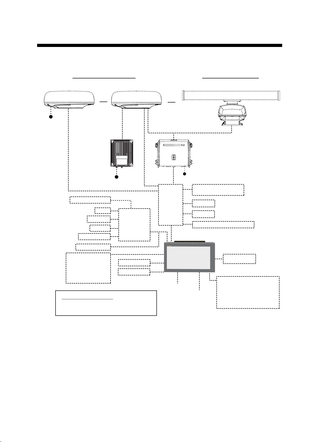
SYSTEM CONFIGURATION
Multi Function Display*3
TZTL12F
or
TZTL15F
Basic configuration is shown with solid lines. Optional equipment is denoted with dashed lines.
12-24 VDC
Radome-type Radar Sensors
DRS4DL
OR
POWER
SUPPLY
1
UNIT*
PSU-017
12-24 VDC
AIS Transponder
SC-30
GP-330B
FI-50/70
NAVpilot-700
DRS2D/DRS4D
For PSU-017
FI-5002
OR
HUB -101
Open-type Radar Sensors
DRS4A/DRS6A/DRS12A/DRS25A
POWER SUPPLY UNIT*
PSU-012/PSU-013
12-24 VDC
Echo Sounder
(BBDS1, DFF series)
FA-30/50
FAX-30
FUSION-Link Equipment*
1
2
IF-NMEA2K1/2
Remote Controller
MCU-002
or
SD Card Unit
SDU-001
Environmental category
Radar antenna: Exposed to the weather
All other units: Protected from the weather
*1 Radar sensor other than the DRS4DL requires a power supply unit.
2
*
FUSION Electronics MS-700 series only (as of 12/2014).
3
*
Max. 4 NavNet TZtouch2 units (connected via Ethernet hub).
Note: When connecting an external monitor to the multi function display, use a monitor whose as-
CCD Camera
CCD Camera
Multi Function Display*3
TZTL12F
or
TZTL15F
Transducer
12/24 VDC
Wide Monitor
Event SW
External Buzzer
Operator Fitness
Power input for NMEA2000
NMEA0183 out
pect ratio is the same as that of the multi function display (16:9). The pictures may be stretched
or shrunk with a different aspect ratio. Output to an HPD (Hot Plug Detect) monitor is not possible.
xiii
Page 15

SYSTEM CONFIGURATION
This page is intentionally left blank.
xiv
Page 16

1. SYSTEM INTRODUCTION
This chapter provides the information necessary to get you started using your system.
Standards used in this manual
• Key names are shown in boldface type. For example, ENT key (on the MCU-002).
• Menu items, on-screen indications, and pop-up menus and pop-up windows names
are shown in brackets. For example, the [Settings] menu.
• Messages shown one the screen (including the Status bar) are enclosed in quotations. For example, "No Network Connected".
• The [Settings] menu is comprised of several sub menus. When you are asked to select one of its sub menus, “[Settings]” is followed by a hyphen and the sub menu
name. For example, “Tap [Settings] - [General]”.
• The colors mentioned in this manual are the default colors. Your colors may be different.
• Most of the screenshots in this manual are taken from the TZTL12F. Layouts may
be slightly different on the TZTL15F.
1-1
Page 17
1. SYSTEM INTRODUCTION
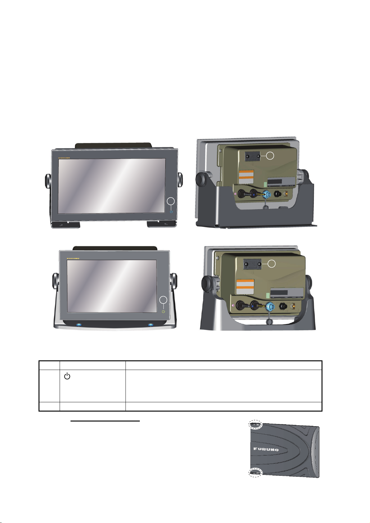
1.1 Controls
The TZTL12F and TZTL15F are operated by a power switch and touch controls.
You operate the plotter, radar, fish finder, etc. with
• Touch control • pop-up menus and hidden functions, where
• Menus, where you select options • Lists, where you can edit items
Your unit has one key on its front panel, a power/brilliance controlling button. The micro SD card slot, which is used for chart data, is on the rear panel.
you select options
2
1
TZTL15F
1
TZTL12F
TZTL multi function display units (shown in optional hanger)
No. Item Function
1
(Power switch)
2 Micro SD card slot Slot for chart micro SD chart cards.
• Turns the power on.
• Adjust the brilliance and hue of the display.
• Turns the power off (device or network).
• Locks, unlocks the touch screen.
2
1-2
About the soft cover
The supplied soft cover protects the LCD when the display unit is not in use. To remove the cover, grasp the
cover at the locations circled in the right figure and pull
forward.
Page 18
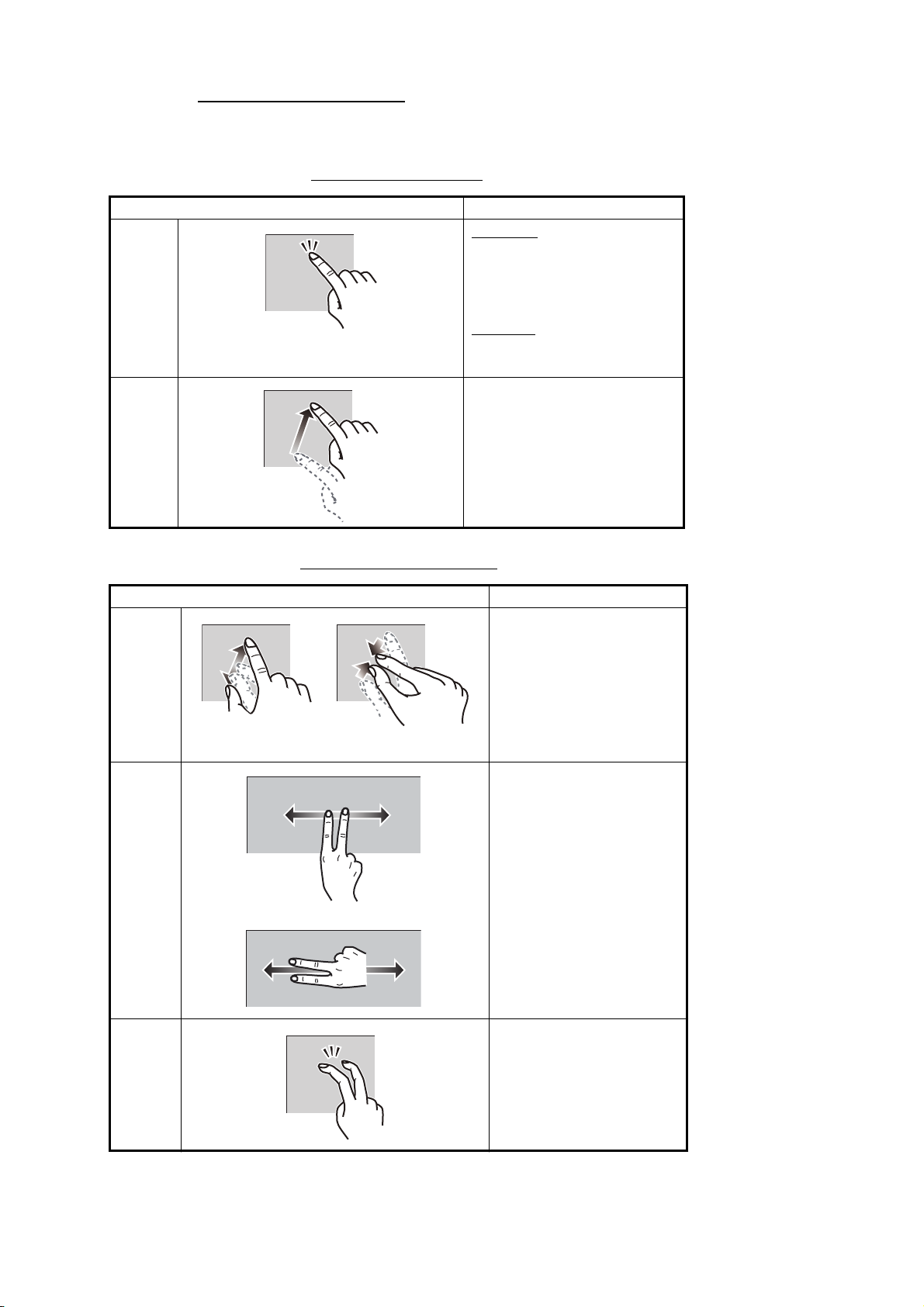
Touchscreen operations
The tables which follow outline the touchscreen operations.
Operation with a finger
Operation with a finger Function
Tap
Drag • Pan the charts.
Short tap
• Select a menu item.
• Select an object or position to display the corresponding pop-up menu.
Long tap
• Edit display icon (on home
screen).
• Scroll the menu.
1. SYSTEM INTRODUCTION
Operation with two fingers
Operation with two fingers Function
Pinch • Zoom in or out the dis-
play range in the 2D/
3D modes or weather
display.
• Select radar range on
the radar display.
Zoom in
Drag Change 3D viewing point.
Zoom out
or
Tap Do the function assigned
to [Function Gesture],
which is in the ([Settings]
- [General] menu. See
section 1.15.
1-3
Page 19
1. SYSTEM INTRODUCTION
Notes on touch control operations
• Waterdrops on the screen can cause mis-operation and slow touch response. Wipe
the screen with a dry cloth to remove the water.
• This equipment uses a capacitive touch screen. Tap the screen with your fingertips
directly. Do not use sharp objects (needle, pen, nail) or a stylus pen. Be careful not
to scratch the screen.
• The touchscreen cannot be operated while wearing gloves.
• Do not put objects (adhesive-backed paper, etc.) on the screen. Mis-operation can
result.
• Keep the equipment away from a radio antenna, fluorescent light, solenoid valve
and electronic devices to prevent unintended operation by noise.
• The front panel is made of glass. If the front panel is damaged, do not try to repair
it yourself. Unauthorized repair will void the warranty. Contact your dealer about repair or replacement.
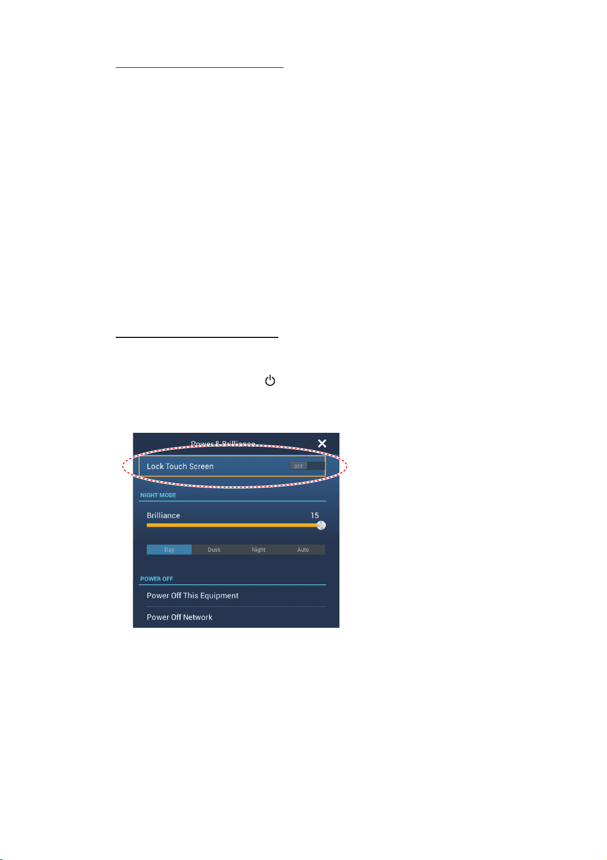
• The touch screen can be locked to prevent operation of the equipment. See the procedure below.
How to lock the touch screen
The touch screen can be locked to prevent unintentional operation.
With the power applied, press to show the [Power & Brilliance] window. Set the flipswitch for [Lock Touch Screen] to the [ON] position to lock the touch screen, or the
[OFF] position to unlock the touch screen.
1-4
Page 20
1. SYSTEM INTRODUCTION
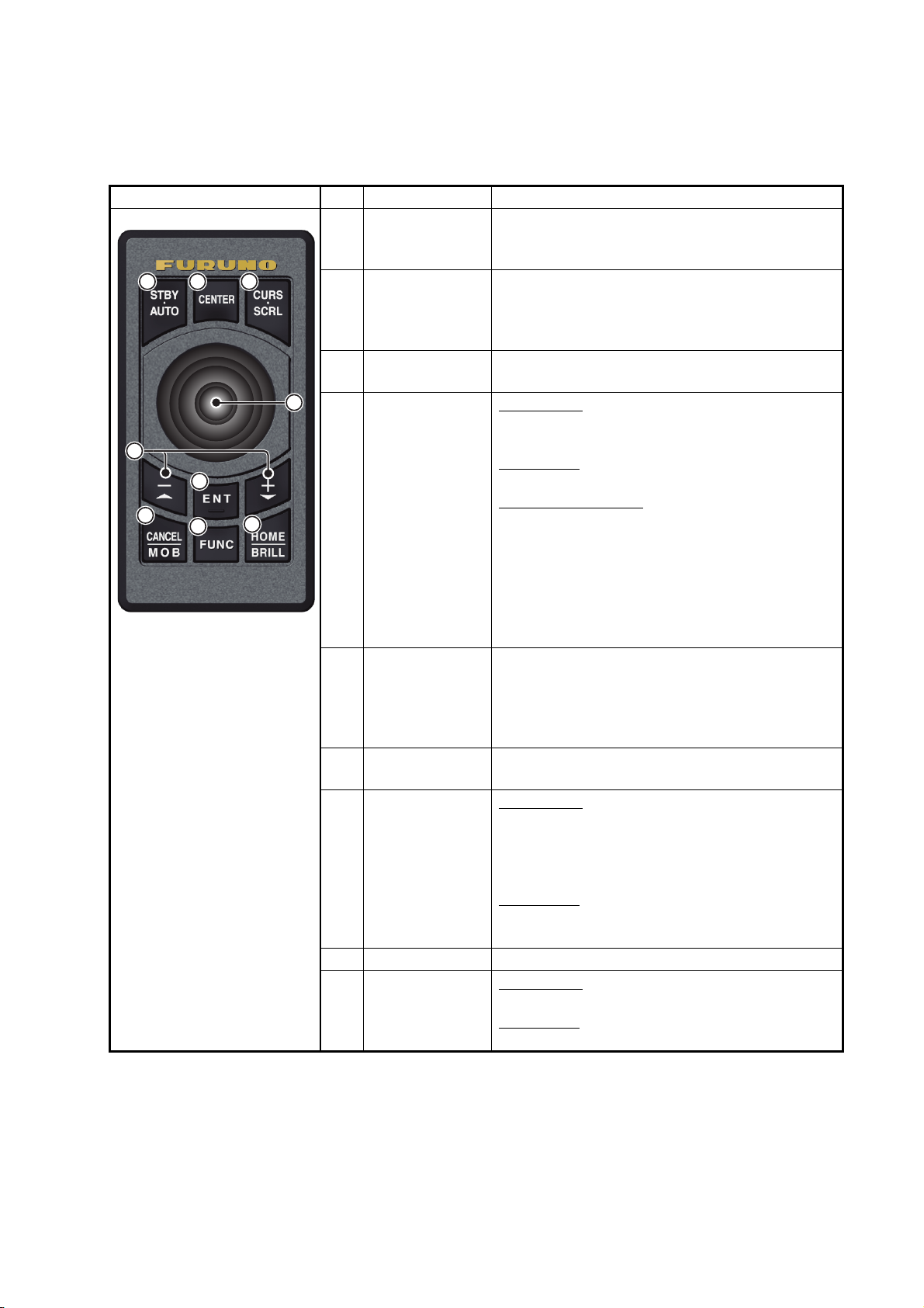
1.2 Remote Control Unit MCU-002 (option)
The Remote Control Unit MCU-002 lets you operate the system without touching the
screen.
No. Key Function
1 2 3
5
6
7
8
* When you switch the steering mode with the STBY.AUTO key, a beep sounds and
then one of the messages shown below appears. The message does not appear on
the home screen.
- STBY modeAUTO mode: "NAVpilot is engaged."
- AUTO modeSTBY mode: "NAVpilot is disengaged."
1 STBY•AUTO
key
2 CENTER key • Returns own ship to the center of the screen
3 CURS•CRL
key
4
9
4 Joystick
5 +, - key • Selects an item from the slide-out/main/pop-
6 ENT key • Activates a selected item.
7 CANCEL/MOB
key
8 FUNC key Does the function set at [Function Gesture].
9 HOME/BRILL
key
Switches the steering mode of the FURUNO
NAVpilot-700 series Autopilot between the
STBY and AUTO modes*.
(Plotter/Weather/Radar display).
• Cancels the echo history (Fish finder display).
Switches the joystick gesture between the cursor mode and scroll mode.
Short press: Works same as tap gesture.
• Opens the pop-up menu.
• Activates the item selected by the cursor.
Long press: Works same as long tap gesture.
• Opens the detail pop-up menu.
Operate the joystick:
Cursor mode operation:
• Moves the cursor.
Scroll mode operation:
• Pans the display (Plotter/Weather/Radar display).
• Shifts the range and scrolls back the picture
(Fish finder display).
up menu.
• Zooms in (+) and out (-).
• Raises (+) and lowers (-) the brilliance on the
[Power & Brilliance] window.
• Opens the slide-out menu.
Short press:
• Closes the menu or dialog box.
• Stops the aural alarm.
• Ends the tool mode (End Route, End Move,
etc.).
Long press:
• Enters the MOB mark (at the own ship’s position).
Short press:
• Opens the home screen.
Long press:
• Opens the [Power & Brilliance] window.
1-5
Page 21
1. SYSTEM INTRODUCTION
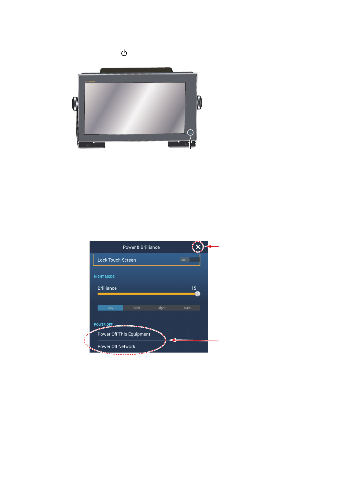
1.3 How to Turn the Power On or Off
The power switch ( ) on the front panel controls the power.
POWER
switch
When you turn on the power, the equipment beeps twice and the start-up screen appears. After the startup process is completed, the [NAVIGATION WARNING] screen
appears. Read the warning, then tap [OK]. Then, the last-used display appears.
The color of the lamp in the power switch changes according to equipment state.
Green: Equipment is powered.
Orange: Equipment is not powered but power is flowing to the equipment.
To turn off the power, tap the power switch to show the [Power & Brilliance] window.
Closes the
window.
Tap either of
these two.
Tap [Power Off This Equipment] or [Power Off Network], then tap [OK].15 seconds after the screen goes blank, the power turns off. (The power is on for this 15 seconds.)
1-6
Note 1: If you cannot turn off the power as shown above or the display freezes, long
push the power switch until the screen goes blank.
Note 2: Do not turn off the power during the start-up. Wait until the start-up is completed before you turn off the power.
Note 3: The screen refreshes slower in low ambient temperature.
Page 22
1. SYSTEM INTRODUCTION
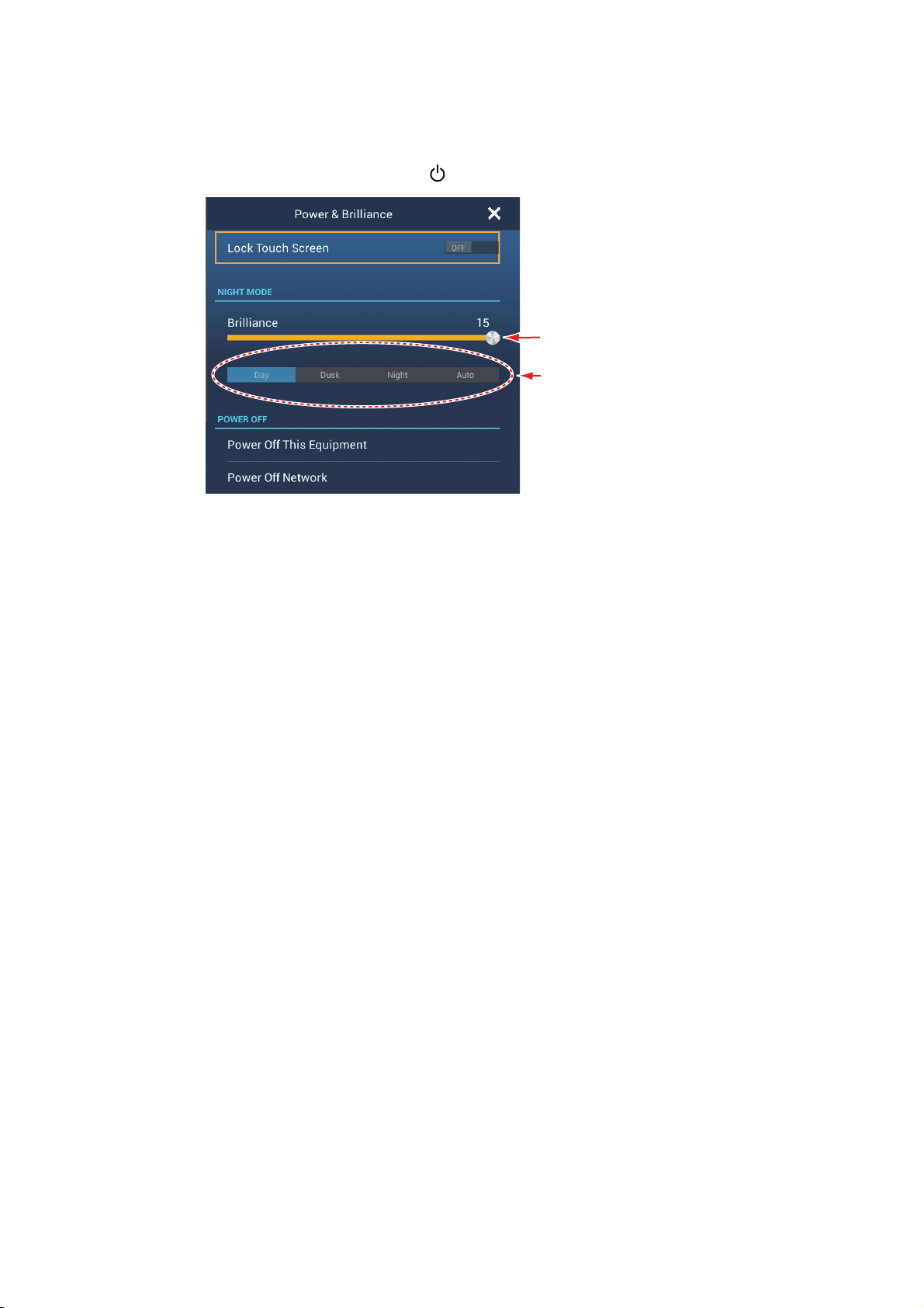
1.4 How to Adjust the Brilliance of the Display and Power Switch and Hue
With the power applied, press to show the [Power & Brilliance] window.
Adjust the display brilliance.
Hue options
Drag the slider or tap the slider bar to adjust the brilliance of both the display and the
power indicator.
The [Day], [Dusk], [Night] and [Auto] options (below the slider bar) set the hue according to selection. The [Auto] option automatically sets the hue according to time of day.
1-7
Page 23
1. SYSTEM INTRODUCTION
Functions
Home screen
Time, date
Sensor icons
Display icons
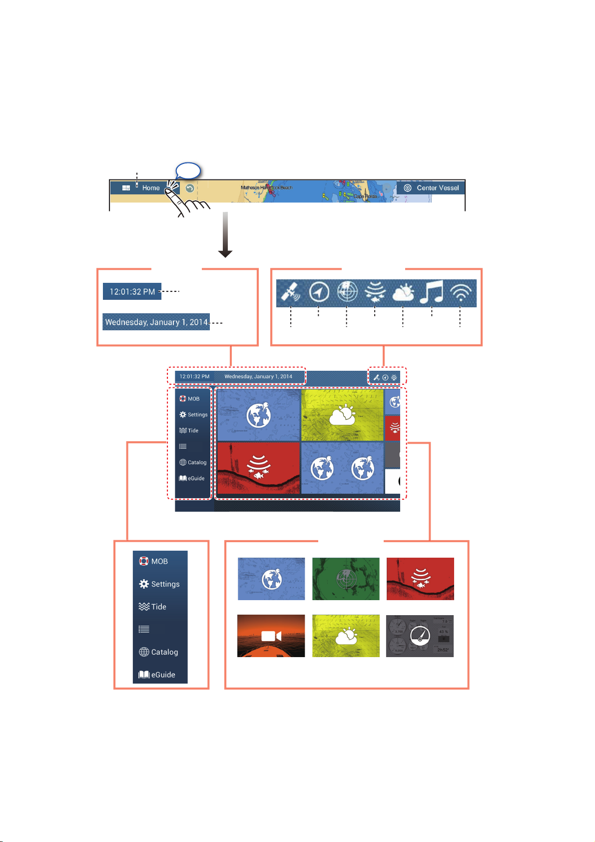
1.5 Home Screen
The home screen is where you access functions and menus, select displays and
check sensor status. Tap the [Home] icon at the top left corner to show the home
screen. The home screen is automatically closed, and the previous operation display
restored, when no operation is detected for approx. one minute.
Home icon
Time, date
Tap
Time
Lists
Date
GPS
Heading
Sensor icons
Sounder
Radar
Sirius
Fusion
WiFi
Lists
Functions
Lists
Home screen
Plotter
Camera
Display icons
Radar
Weather
Sounder
Instrument
The Sensor icons show the sensors connected in the system and their status, by color.
White: Sensor normal
Red: Sensor error
Gray: Sensor inactive (stopped)
1-8
Page 24
The Functions section provide the following features:
[MOB]: Enters a MOB mark (to mark man overboard location on the plotter and radar
displays). See section 1.17.
[Settings]: Menus (general, plotter, radar, sounder, etc.) for customization of the system. See section 1.14.
[Tide]: Opens the tide graph.
[Lists]: Accesses the lists (points, routes, AIS, DSC, ARPA, Alarms).
[Catalog]: Opens the list of charts installed in your system.
[eGuide]: Opens the abbreviated operator’s manual. You can get the latest version of
the operator’s manual by accessing the quick response code provided in the introduction section of the guide.
The Display icons select corresponding displays. See the next section for details.
1.6 How to Select a Display
You have two methods from which to select a display, the home screen and the quick
page.
1. SYSTEM INTRODUCTION
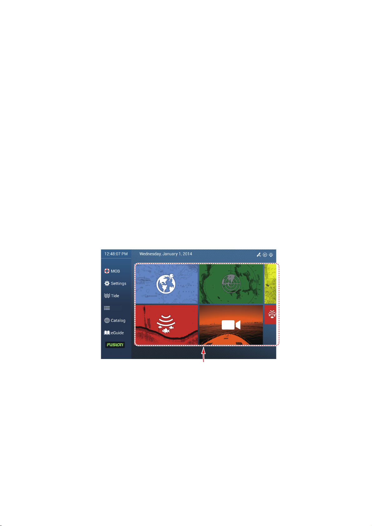
1.6.1 How to select a display from the home screen
Tap the [Home] icon to show the home screen. Tap the applicable display icon. (It may
be necessary to swipe the screen if you have programmed a number of display icons.)
Lists
Display icons
1-9
Page 25
1. SYSTEM INTRODUCTION
Swipe
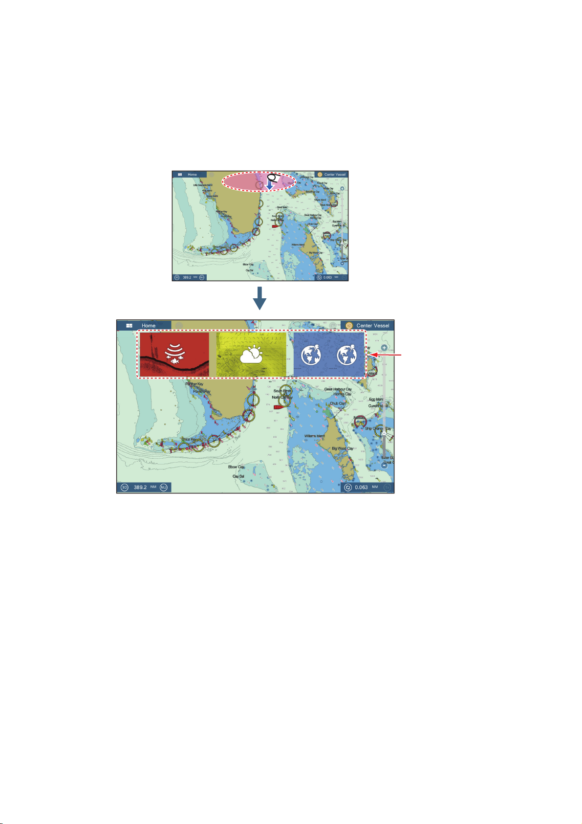
1.6.2 How to select a display from the quick page
The quick page, which carries all the display icons set for large size on the home
screen, lets you change the display from the current display.
To show the quick page, swipe the top of the screen downward. Tap desired display
icon to change the display. (It may be necessary to scroll the display icons if you have
there are several icons.)
Swipe
Quick page
1-10
Page 26
1.7 How to Edit the Display Icons
Custom display area
Drag
display
division
Drag
display
type
The default home screen arrangement provides seven displays (icons) in configurations according to the equipment that you have in your network. If the arrangement
does not meet your requirements, you can change the display icons to suit your
needs. You can have a maximum of 10 display icons, in full screen, 2-way or 3-way
split screens. For example, you can show the radar and sounder (fish finder) displays
in a two-way split screen.
The displays available depend on the display division selected and your system configuration. The table below outlines the display divisions and available displays.
Display division Available displays
Full screen Plotter, weather, radar, sounder, instrument, camera
Two-way split Plotter, radar, sounder
Three-way split Plotter, radar, sounder, instrument, camera
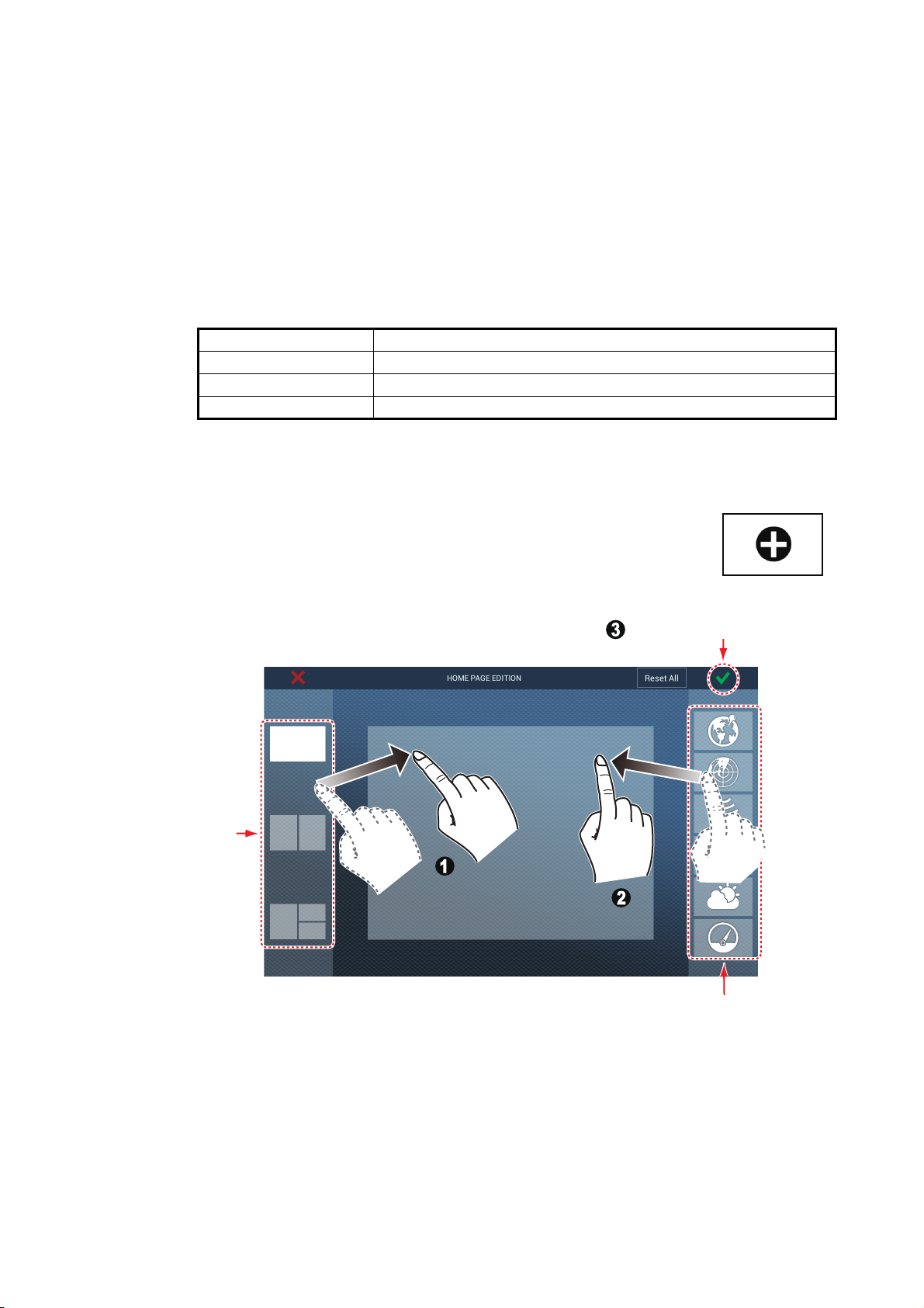
1.7.1 How to add a new display icon
1. Tap the [Home] icon to show the home screen.
1. SYSTEM INTRODUCTION
2. Tap the + icon, shown right. (If the icon is not shown, this means
that all available display icons have been used. Erase an unnecessary icon to make room. See paragraph 1.7.2.)
3. Follow the instructions below to create a display icon.
Tap to save icon.
Custom display area
Display
division
choices
Drag
display
division
Drag
display
type
Display
choices
Your arrangement is then opened on the screen and the home screen is updated according to your arrangement.
1-11
Page 27
1. SYSTEM INTRODUCTION
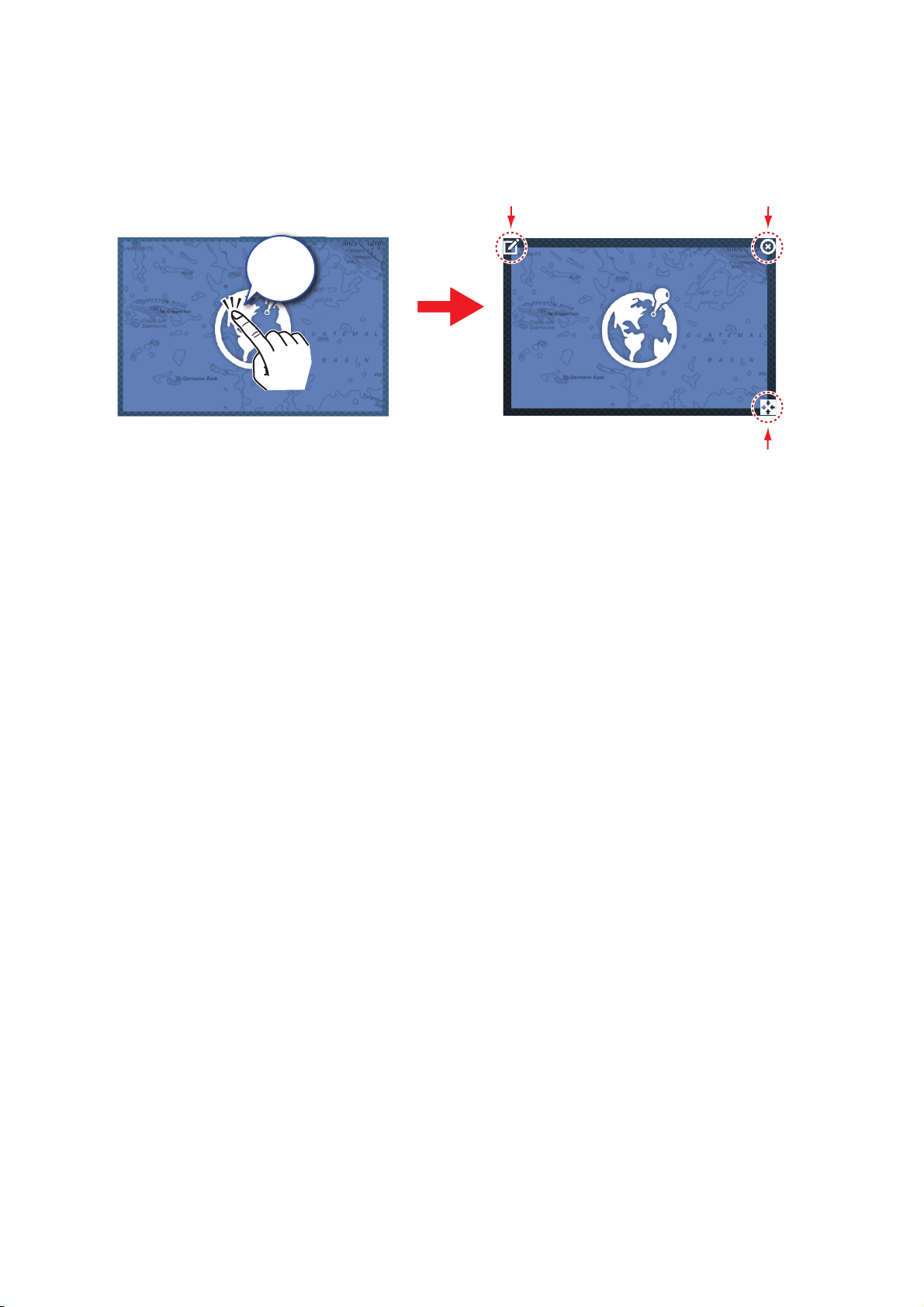
1.7.2 How to edit a display icon
Long tap the display icon to edit to show the editing icons on the display icon. Tap the
applicable editing icon. Refer to the figure and instructions below.
Edit icon content
Long
tap
Remove icon
Change icon size
Edit icon content: Tap the icon at the upper left corner. See the illustration in
paragraph 1.7.1 for how to set the icon.
Remove icon: Tap the icon at the upper right corner to remove the icon from the home
screen (and quick page if the icon size is selected to “large”.
Change icon size: Tap the icon at the lower right corner to switch the size between
large and small. (Icons set for large size appear on the quick page.)
1-12
Page 28
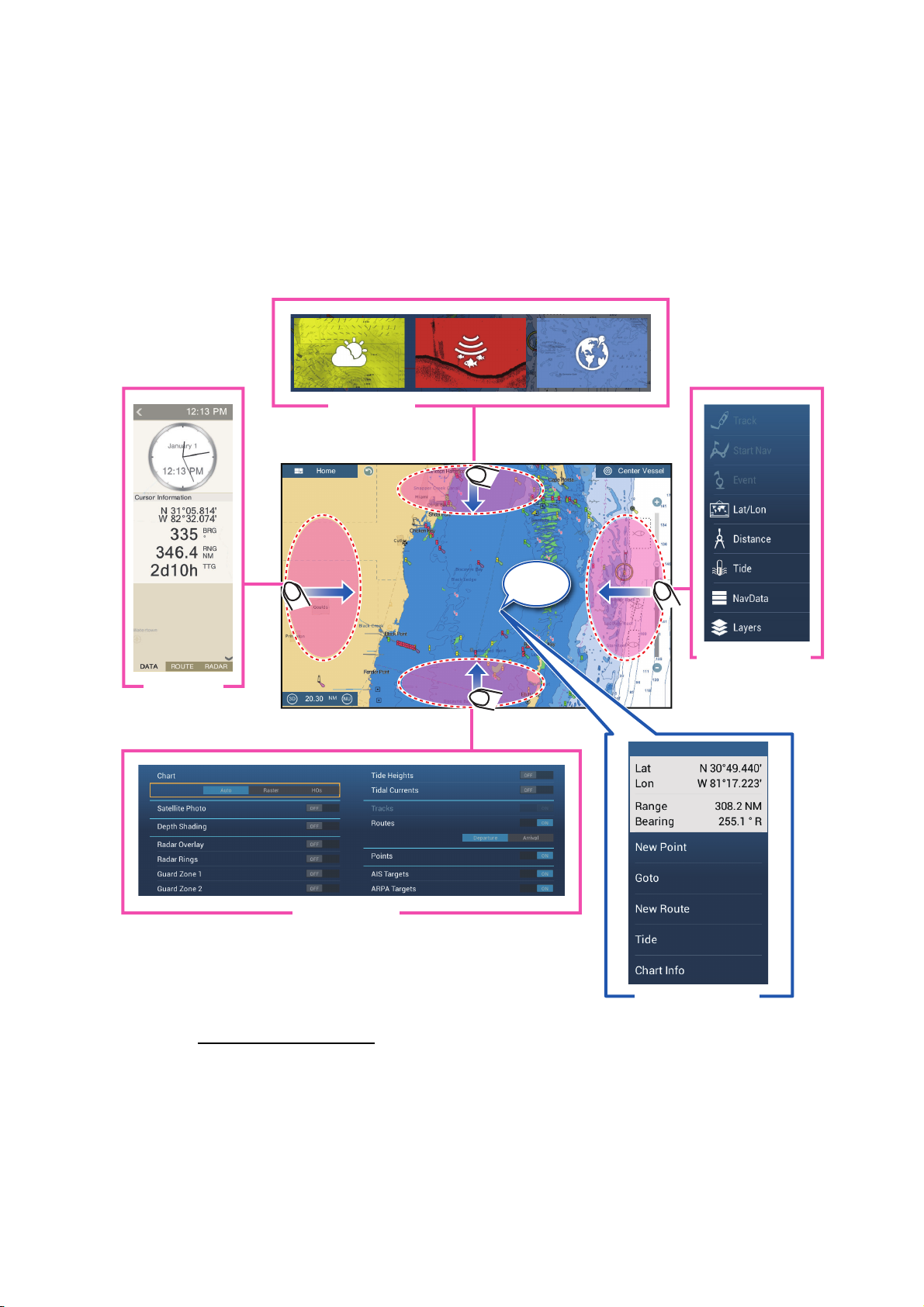
1.8 Hidden Functions
Swipe
Swipe
Swipe
Swipe
This equipment has five functions that are normally hidden from view: quick page,
slide-out menu, pop-up menu, [Layers] menu, and data area (navdata). Swipe or tap
the screen at the locations shown below to access the hidden functions.
A function window is automatically erased from the screen when it is not operated
within the time specified with [User Interface Auto-Hide] in the [General] - [Settings]
menu. You can erase the window at any time by tapping the screen.
Quick page
Swipe
1. SYSTEM INTRODUCTION
Swipe
Swipe
Data area
Swipe
Layers menu*
* Plotter display, radar sensor connected. [Radar Overlay],
[Radar Rings], [Guard Zone 1] and [Guard Zone 2] do not
appear with no radar sensor connection.
Tap
Swipe
Slide-out menu
Pop-up menu
Function description
The quick page selects displays. The display icons set to large size appear on the
quick page. (See paragraph 1.6.2.)
The slide-out menu provides quick access to often-used functions in the active display. The color of the function name changes according to function status. Unavailable
functions are grayed out.
1-13
Page 29
1. SYSTEM INTRODUCTION
The pop-up menu provide a subset of functions that are relevant to the object or location tapped. Unavailable functions are greyed out.
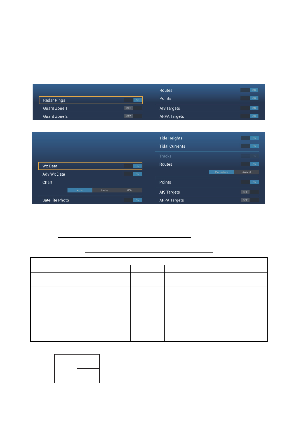
The [Layers] menu controls the items that are displayed on the top layer of the active
display. Unavailable functions are greyed out. (This menu can also be accessed from
the slide-out menu in some modes. The figure below shows the [Layers] menu for the
radar and weather displays.
Layers menu for radar display
[Layers]
menu
Pop-up
menu
Data
area
Quick
page
Slide-out
menu
Layers menu for weather display
The data area shows navigation data. See the next section for details.
Hidden function availability and screen division
Full screen displays and hidden function availability
Display
Camera Instrument Plotter Radar Sounder Weather
No No Yes Yes No Yes
Yes Yes Yes Yes Yes Yes
Yes Yes Yes Yes Yes Yes
Yes Yes Yes Yes Yes Yes
Yes Yes Yes Yes Yes Yes
1-14
B
A
C
A: Data area, [Layers] menu, pop-up menu, quick page
B: [Layers] menu, pop-up menu, quick page, slide-out menu
C: Pop-up menu, slide-out menu
Three-way split-screen and hidden function availability
Page 30
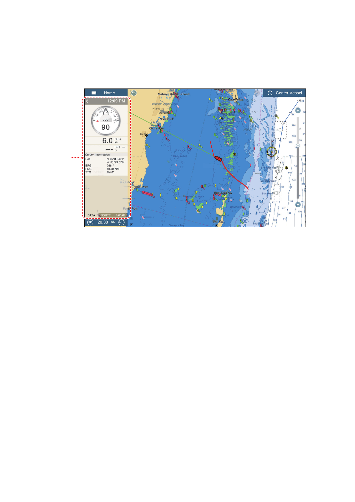
1.9 Data Area
Data
area
The data area at the left side of the screen shows various navigation data, in movable
and editable data boxes. You can select the data to display, select format (analog or
digital) for data and change the order of the data. Data availability depends on your
system configuration.
Data
area
1. SYSTEM INTRODUCTION
Note: The data display is also available in the two- and three-way split screens, on the
left screen.
Two types of data sets* are available, navigation data, route data, and radar. Select
the desired set with [DATA], [ROUTE] or [RADAR]* at the bottom of the data area.
* With connection of radar sensor.
1.9.1 How to change the order of the data
Drag and drop the data boxes to change their order.
1-15
Page 31

1. SYSTEM INTRODUCTION
1.9.2 How to change the contents of a data box
Tap the data box to change, and the [Modify NavData] pop-up menu appears. Tap the
data to use, on the pop-up menu.
Tap i tem
to change
Tap a n
item
1.9.3 How to add data to a data area
1. Tap an unoccupied area in the data area to display the [Add NavData] pop-up
menu.
1-16
Page 32

1. SYSTEM INTRODUCTION
2. Tap the data to add, on the pop-up menu. For example, tap [Cursor].The added
data appears in the data area.
1.9.4 How to delete a data box
Tap the data box to delete, then tap [Remove] on the [Modify NavData] pop-up menu.
1-17
Page 33

1. SYSTEM INTRODUCTION
avvDDa
a
1.9.5 How to switch an indication between analog (graphic) and digital
Tap the data box for which to switch the indication, and the [Modify NavData] pop-up
menu appears. Use the [Graphic] flipswitch to switch between analog and digital indications. [ON] for analog, or [OFF] for digital.
Modify NavData
ON
ON
[ON]: Analog display
Modify NavData
[OFF]: Digital display
t
OFF
1.9.6 How to adjust the transparency of the data area
You can adjust the degree of transparency for the data box with [NavData Transparency] in the [Settings] - [Plotter] menu. The available degree of transparency is 0 80(%).
Note: Alpha blending technology is used for transparency effects.
1-18
Page 34

1.10 Micro SD Cards
This equipment uses two types of micro SD cards, chart and data. The chart cards
contain charts and the data micro SD card stores plotter-related data such as tracks,
routes, points and generic data such as menu settings. Set and remove the card as
shown below. The Secure Digital Extended Capacity (SDXC) cards can also be used.
How to insert a micro SD card
Before inserting a chart card in the multi function display, turn off the power.
1. SYSTEM INTRODUCTION
Push card
into slot*
and close
cover.
Unfasten two
screws.
Push card into slot
and close cover.
Open cover.
* Right slot is for data card; left slot is for chart
card.
SD card unit (SDU-001)Chart card drive (multi function display)
How to format a micro SD card
You do not normally need to format a data micro SD card. If the card becomes unreadable, format the card with a formatting program that is compatible with the specifications of the card.
How to remove a micro SD card
1) Open the card drive cover.
2) Push the card to release the card from the card drive.
3) Remove the card with your fingers then close the lid (cover).
About the micro SD cards
• Handle the cards carefully. Improper use can damage the card and
destroy its contents.
• Make sure the slot lid (cover) is closed at all times.
• Remove a card with only your fingers. Do not use metal instruments
(like tweezers) to remove the card.
• Do not remove a card during the reading of or writing to the card.
Note: Use a micro SD card class 6 or higher for storing chart data.
1-19
Page 35

1. SYSTEM INTRODUCTION
Compatible micro SD cards
The table below lists the micro SD cards that have been verified for use with this equipment.
Maker Model Capacity (GB) Class
KINGMAX KM-MCSDXC10X64GUHS1P 64 10
KM-MCSDHC10X32GUHS1P
KM-MCSDHC4X32G 4
KM-MCSDHC10X16GUHS1P
KM-MCSDHC4X16G 4
Kingston SDCX10/64GB 64 10
SDC10/32GB
SDC4/32GBS 4
SDC10/16GB
SDC4/16GB 4
SDC10/8GB
SDC4/8GB 4
Lexar Media LSDMI64GABJPC10 64 10
LSDMI32GABJP 32 10
LSDMI16GABJPC6 16 6
LSDMI8GBABJPC6 8 6
SANDISK SDSDQX-064G-U46A 64 10
SDSDQ-032G-J35A 32 4
SDSDQ-016G-J35A 16 4
SDSDQU-008G-J35A
SDSDQ-008G-J35A 4
Silicon Power SP064GBSTXBU1V10-SP 64 10
SP032GBSTHDU1V10-SP
SP032GBSTH004V10-SP 4
SP016GBSTHDU1V10-SP
SP016GBSTH004V10-SP 4
SP008GBSTHBU1V10-SP
SP008GBSTH010V10-SP 4
Transcend TS64GUSDU1 64 10
TS32GUSDU1
TS32GUSDC4 4
TS16GUSDHC10U1
TS16GUSDC4 4
TS8GUSDHC10U1
TS8GUSDC4 4
32
16
32
16
8
8
32
16
8
32
16
8
10
10
10
10
10
10
10
10
10
10
10
10
1-20
Page 36

1.11 Plotter Introduction
COG
Boat icon
Data
area
Heading
line
The plotter provides a small world map in raster format. A vector chart for the US
coastline (with Alaska and Hawaii) is provided also. The plotter section has functions
to enter points, and create and plan routes.
The plotter receives position data fed from the built in GPS receiver. Your position is
marked on the screen with the boat icon.
The points and routes you have entered are shown on the screen. You can move, delete and edit the points and routes from a pop-up menu.
The plotter also
1. SYSTEM INTRODUCTION
• Plots the track of your ship
• Measures distances and bearings
• Marks man overboard (MOB) position
Home icon
Data
area
• Controls alarm functions
• Follows routes
Undo icon Redo icon
Depth Alarm
Heading
line
Status bar
COG
Boat icon
Return own
ship to screen
center
Slider bar
Inactive route
(expanded)
Point
Track
Chart range
2D/3D switch
The status bar, common to all modes, alerts you to equipment status. The color of
both the bar and the status message change according to message category.
• Red bar, yellow characters: warning (alarm violation, equipment error, etc.)
• Yellow bar, black characters: caution (system message, etc.)
When an alert condition occurs, the equipment beeps (if enabled), the name of the
alert appears in the bar, and the bar flashes. You can stop the flashing and silence the
beep by tapping the bar. The alert indication remains in the status bar until the cause
for the alert is removed.
The undo and redo icons are available for point and route operations.
Undo: Reverse the last action.
Redo: Repeat the last action.
Orientation mode switch
Inactive route
(sleeping)*
* Arrival or departure position,
selectable on [Layers] menu.
1-21
Page 37

1. SYSTEM INTRODUCTION
Own ship position
Guard zone
North mark
Data
area
Heading line
Data
area
1.12 Radar Introduction
A radar system operates in the microwave part of the radio frequency (RF) range. The
radar detects the position and movement of objects. Objects are shown on the radar
display at their measured distances and bearings in intensities according to echo
strength.
The radar display is available in head-up and north-up modes and orientation in true
and relative motion. The relative motion display shows other ships movement relative
to your ship. The true motion display shows your ship and other objects in motion according to their true courses and speeds.
A guard zone tells you when the radar targets are in the area you indicate. The trail of
targets can be shown in afterglow to monitor their movements.
㔎㔐
Radar Control
DATA
Home icon
2:01 PM
Data
Data
area
area
RADAR
ROUTE
Undo icon
Guard zone
190
180
170
160
150
220
210
200
140
130
120
North mark
240
230
110
100
260
250
270
90
80
Heading line
280
60
70
Redo icon
290
300
40
50
310
320
330
340
340
350
Return own
ship icon to
screen
center.
Slider
bar
0
10
20
30
TX
1-22
Own ship position
Fixed range
rings
TX/Standby
switch
Orientation mode switch
Page 38

1. SYSTEM INTRODUCTION
1.13 Sounder (Fish Finder) Introduction
The sounder display provides a picture of the echoes found by the fish finder. Echoes
are scrolled across the screen from the right position to the left position.
The echoes at the right position are the current echoes. These echoes can be from
separate fish, a school of fish, or the bottom. Depth to the bottom is indicated always,
provided the gain is set correctly. You can scroll the echoes backward.
Both low and high TX frequencies are provided. (Frequencies depend on the transducer connected.) The low frequency has a wide detection area, which is for general
detection and understanding bottom conditions. The high frequency has a narrow
beam that helps you inspect fish.
The range, gain, clutter and TVG can be adjusted automatically according to your purpose (cruising or fishing) to let you do other tasks.
Home icon
Temp.
scale
Bottom
echo
Slider
*2
bar
39.6
HF
ft
Depth, frequency
*1
Requires appropriate transducer.
*2
Requires water temperature sensor.
Temp graph
*2
Depth
scale
29.8 ft
29.6 ft
Fish
mark
*1
A-scope
display
1-23
Page 39

1. SYSTEM INTRODUCTION
1.14 Settings Menu
The [Settings] menu provides the options for customizing your system. The [Settings]
menu, as well as all other items on the home screen, is automatically closed, and the
previous operation display restored, when no operation is detected for approx. one
minute.
1. Tap the [Home] icon to go to the home screen.
2. Tap [Settings].
Back button
Sub menus
Menu name
Preview screen shows you the result
of certain selections.
3. Tap a sub menu. For example, tap the [General] sub menu.
Close button
Title bar
4. Do one of the following according to the menu item:
• ON/OFF flipswitch: Tap the flipswitch to switch between [ON] and [OFF].
Flipswitch
• Slider bar, keyboard: Set level by dragging the slider, or tapping the keyboard
icon ( ) to enter the level with the numeric software keyboard. (See the
next page for the appearance of the numeric keyboard.)
Slider bar
Tap to show
keyboard.
1-24
Page 40

1. SYSTEM INTRODUCTION
• Alphabet, numerical data entry: A menu item that requires entry of alphabet
and/or numerical data has a keyboard icon ( ). Tap the keyboard icon to
show the keyboard. (The keyboard displayed depends on the item selected.
Some items provide only the numeric keyboard.) Enter data, then tap to confirm.
Cancel
Cursor (light blue)
Alphabet keyboard
Title
Close window
Erase
line
Delete selected
character
Confirm
entry
Shift cursor
Switch to numeric keyboard
Numeric keyboard
Switch to alphabet keyboard
1-25
Page 41

1. SYSTEM INTRODUCTION
• Color selection: A menu item that requires selection of color shows the current
color selection to the right of the name of the menu item. Tap the menu item to
show the color options. Tap color option desired. Current selection is highlighted with a light blue square.
Current
selection is
highlighted
in light blue.
• Option selection: A menu item that requires selection of an option shows the
current selection on the menu. Tap the option desired. The current selection
has a checkmark.
Tap menu item.
Tap menu item.
Current selection
Current selection
Current
selection
has a
checkmark.
5. Tap the close button to finish.
Note: The title bar (top of menus) does not appear in menu illustrations hereafter unless its inclusion is necessary in a description.
1-26
Page 42

1.15 Function Gesture
The function gesture controls what occurs when you tap the screen with two fingers.
Select the function as below.
1. Open the home screen, then select [Settings] - [General].
2. Tap [Function Gesture].
1. SYSTEM INTRODUCTION
3. Tap a function among the following:
[None]: Nothing happens.
[Screen Capture]: Capture the screen and save it to a micro SD card (or USB
memory). The message shown below appears. Tap [OK] to save the screen capture. The information following “TZT2SCREENSHOT” is the year, month, day,
hour, minute and second the screenshot was captured.
[Event]: Record an event. Select a mark from the pop-up menu, and the mark is
put at the position at the time the screen was tapped (see paragraph 4.2.2). The
position, etc. is saved to the points list.
[Home]: Open the home screen (see section 1.6).
[Settings]: Open the [Settings] menu (see section 1.14).
1-27
Page 43

1. SYSTEM INTRODUCTION
[Lists]: Open the lists menu (see section 1.14 and section 4.9).
[Tide]: Open the tide graph (see section 1.14 and paragraph 3.2.4).
4. Tap the close button to finish.
1.16 Language
The default interface language is English (United States). To change the language, do
as follows:
1. Open the home screen, then tap [Settings] - [General].
2. Tap [Language].
1-28
3. Tap the language to use. The message "APPLICATION HAS TO RESTART
NOW! DO YOU WANT TO RESTART APPLICATION?" appears.
4. Tap [OK].
This process takes approximately five minutes to optimize the system for the new language setting. When the process is completed, the power switch will change color to
orange. Press the power switch to start the system.
Page 44

1.17 Man Overboard (MOB)
The MOB function is used to mark the location of man overboard, from the plotter and
radar displays. At the moment the MOB function is activated, the MOB mark is put at
the current position, on both the plotter and radar displays.
How to mark the MOB position
Tap [MOB] on the home screen. The plotter display opens, the MOB mark ( ) is at
the location at the moment MOB was activated, and the MOB location is automatically
set as destination. At the moment of activation the following occurs.
• The message "MOB" flashes in the status bar, with yellow characters on a red background. The aural alarm sounds if it is enabled. Tap the status bar to stop the flashing indication and silence the aural alarm.
• The MOB mark is highlighted.
• A yellow line connects between the MOB mark and current location. This line shows
the straightest course between own ship and the MOB mark.
1. SYSTEM INTRODUCTION
MOB mark on the plotter display
MOB mark on the radar display
MOB information
Tap a MOB mark to display the name, comment and depth (plotter display only).
How to delete a MOB mark
Inactive MOB mark: Tap a MOB mark to display the pop-up menu. Tap [Delete].
Active MOB mark: Before you can erase an active MOB mark, you must stop navi-
gation (to the MOB). Tap the active MOB mark to display the pop-up menu then select
[Stop Nav]. Tap the MOB mark to display the pop-up menu, then tap [Delete].
1-29
Page 45

1. SYSTEM INTRODUCTION
1.18 Wireless LAN Settings
You can connect to the internet with the wireless LAN signal to download weather in-
formation (see chapter 11) and to connect to an iOS or Android
weather information, connect the existing LAN network. To connect to an iOS or An-
droid™ device, create a local wireless network.
About the wireless LAN
• The wireless LAN function is available only in the countries which have acquired radio wave certification. Turn this function off in countries which do not have radio
wave certification. Ocean-going vessels that have radio wave certification can use
the wireless LAN function in any country that has acquired radio wave certification.
Vessels with radio wave certification that enter a country that does not have radio
wave certification may use the wireless LAN function only onboard the vessel.
Available countries (as of 12/2014): USA, Canada, New Zealand, Australia, and Japan.
• The communication rate and effective range for the wireless LAN can be affected
by the electromagnetic wave, interfering object, or access point location.
™
device. To download
• We strongly recommend using the wireless LAN with encrypted connection. Otherwise unauthorized access by a third party can occur, which can cause loss of data
or system crash.
• We recommend changing the initial password when using a local wireless network.
1.18.1 How to connect the existing LAN
1. Open the home screen, then tap [Settings] - [General].
2. Tap [Connect to the Internet].
3. Tap [When Necessary]. Tap “<“ to go back one layer.
4. Tap [Wireless LAN Settings].
5. Tap [Wireless Mode].
1-30
6. Tap [Connect to existing LAN]. Tap “<“ to go back one layer.
Page 46

1. SYSTEM INTRODUCTION
7. Turn on [Wireless] to see the available WLAN networks at the bottom of the
screen.
8. Tap the desired network to show the network key (password) entry screen.
9. Enter the network key, then tap [OK]. The IP address, security type and signal
strength of the WILAN are shown.
1.18.2 How to create a local wireless network
Note 1: Do the procedure with [Local Network] in [Wireless LAN Settings] turned off.
Note 2: It may not be possible to connect to a local network if the network is unstable.
In this case, turn [Wireless] off and on. Connect via existing LAN network.
Note 3: Confirm that [When Necessary] is selected in [Connect to the Internet] before
doing the procedure.
1. Open the home screen, then tap [Settings] - [General].
2. Tap [Wireless LAN Settings].
3. Tap [Wireless Mode].
4. Tap [Create Local Network], then tap “<“ to go back one layer.
5. Tap [Name].
6. Enter the name of the network, then tap [OK].
7. Tap [Password].
8. Enter the password, then tap . (If the password is wrong, an error message appears. Tap the [OK] button then reenter the password.)
9. Turn on [Local Network] in [Wireless LAN Settings] to connect to the network.
1.18.3 How to forget all wireless LAN
1. With [Connect to existing LAN] selected in [Wireless Mode] and [Wireless] turned
on, select [Forget all Networks].
2. Tap [Yes].
1-31
Page 47

1. SYSTEM INTRODUCTION
1.18.4 Operation by wireless terminal
You can turn on or off the operation by a wireless terminal via wireless LAN (iPhone,
™
iPod, iPad, or Android
1. Open the home screen, then tap [Settings] - [General].
2. Tap [Allow Remote Control].
[Off]: Cannot operate this equipment by a wireless terminal.
[View Only]: Cannot operate this equipment but can display the data on the
screen of the wireless terminal.
[Full Control]: Can fully operate this equipment by a wireless terminal.
3. Tap the close button to finish.
device).
1-32
Page 48

2. PLOTTER
This chapter shows you how to do the following:
• Use and prepare the plotter display
• Set plotter related alarms
• Control the track
2.1 Chart Type
A world map in raster chart format is included in your unit. A vector chart for the US
coastline (Alaska and Hawaii included) is provided also. To use this plotter as a navigational aid, have electronic charts (stored in the hard disk) for the area you navigate.
Contact your dealer about charts for your area.
There are two types of charts available with this equipment.
[Raster]: Raster charts are digitized scans of NOAA paper charts. Raster charts have
information like notes, source diagrams, tidal diamonds, horizontal and vertical datum,
etc.
[HO]: HO charts are S-57 format vector charts (digital files) that contain marine features and information created for marine navigation. These charts are made according
to the International Hydrographic Organization (IHO). HO charts are available from
Jeppensen, Navionics, Mapmedia, and NOAA (National Oceanic and Atmospheric
Administration).
How to select a chart type
1. Select the plotter display.
2. Open the [Layers] menu.
3. Tap the chart type from among [Auto], [Raster] or [HOs].
*: [Auto] automatically switches the chart type according to chart availability and priority.
2-1
Page 49

2. PLOTTER
Range area
2.2 Display Range
You can change the display range to change the amount of information shown. The
selected range appears in the box at the bottom left-hand corner of the screen.
How to zoom in or out the display range
Range area
Display range
Method 1: Pinch the plotter display.
Zoom in
Zoom out
Method 2: Operate the range slider at the right side of the screen. Drag the slider, tap
the bar or tap the “+” or “-” icon (above and below the slider) to set the display range.
(The slider bar is shown in the default setting. The slider bar can be shown or hidden
with [Show Scale Slider] in the [Settings] - [Plotter] menu.)
Zoom in
Drag the slider
(or tap bar or +, - icons)
Zoom out
Slider bar
2-2
Note 1: You can judge the suitability of the range by the color of the range indication.
White: Range is appropriate; normal chart accuracy.
Red: Range is inappropriate; unsuitable chart accuracy.
Note 2: You can zoom in or out the display range on the preview screen.
Page 50

2.3 Orientation Mode
The chart can be shown in head-up or north-up orientation. Tap the orientation mode
switch, [HU] or [NU], whichever is shown, at the bottom left corner to change the orientation mode.
North Up: North is at the top of the screen. When your heading changes, the boat icon
moves according to heading. This mode is for long-range navigation.
Head Up: Displays the chart with the current compass heading of your ship at the top
of the screen. The heading data from a compass is required. When the heading
changes, the boat icon remains fixed, and the chart picture rotates according to heading.
2. PLOTTER
Orientation
mode switch
2.4 How to Move the Chart
Move the chart in the following conditions.
• Your ship is not in the current area
• Take a look at another area
• Enter a point at another location
Do the following to move the chart:
• Change the display range (section 2.2).
• Tap [Center Vessel] at the top right-hand corner of the screen to return your ship to
the center of the screen.
• Switch to the 3D display by tapping the 3D icon at the bottom left corner.
: North-up
: Head-up
2-3
Page 51

2. PLOTTER
2.5 The Boat Icon
2.5.1 Description
The boat icon (red) marks current position and moves according to your vessel’s
movement.
• The heading line is a straight line that runs from your position and shows the cur-
rent heading.
Heading line
Turn direction
indicator
COG vector
• The COG vector is a vector line that runs from the boat icon and points in the direc-
tion in which your ship is now moving.
• The turn direction indicator points in the direction your vessel is turning, starboard
or port. in the figure above, the starboard turn indicator is shown.
2.5.2 How to show or hide the COG vector, heading line
Tap the boat icon to show the pop-up menu. [COG] controls the COG vector; [HDG]
the heading line. Note that the turn direction indicator is also turned on or off with
[COG].
2-4
Page 52

2.5.3 COG vector length
The COG vector shows estimated course and speed of your ship. The tip of the vector
is the estimated position of your ship at the end of the selected predictor time or distance (set on the menu). You can increase the length of the predictor to find the estimated position of your ship in the future on the current course and speed. You can set
the COG vector as follows. The greater the distance or the time, the longer the COG
vector.
1. Open the home screen, then tap [Settings] - [Ship & Track].
2. Tap [COG Vector].
3. Tap [Distance] or [Time]. For [Distance], do steps 1) and 2) below. For [Time], go
to step 4.
2. PLOTTER
1) Tap [COG Vector Length] to display the software keyboard.
2) Set the length for the COG vector, then tap . Go to step 5.
4. Tap [COG Vector Time], then tap the time for the COG vector.
5. Tap the close button to finish.
2-5
Page 53

2. PLOTTER
2.5.4 Boat icon orientation
You can select the orientation of the boat icon to heading or COG.
1. Open the home screen, then tap [Settings] - [Ship & Track].
2. Tap [Vessel Icon Orientation].
3. Tap [Heading] or [COG].
4. Tap the close button to finish.
2.6 How to Information About a Chart Object, Chart
You can find chart object and chart information from the pop-up menu.
2.6.1 Chart object information
Simple information
Tap an object to show its name, specifications, position, and range and bearing, in the
pop-up menu.
Name and specifications of object
Latitude and longitude position
of object
Range and bearing to object
2-6
Page 54

2. PLOTTER
Detailed information
Tap an object to show the pop-up menu. Tap [Chart Object info] on the pop-up menu
to show detailed information.
2.6.2 Chart information
Tap a location on the chart not occupied by a chart object, then tap [Chart Info] on the
pop-up menu.
2-7
Page 55

2. PLOTTER
2.7 How to Find the Range and Bearing Between Two Locations
The [Distance] item in the slide-out menu measures the range and bearing between
any two locations on your chart. Range and bearing between the two locations are digitally indicated on the screen.
1. Open the slide-out menu.
2. Tap [Distance].
A dashed line runs between the start location and the 2nd location. The range,
bearing, SOG, and TTG to the 2nd location is shown at the top of the screen.
Speed Over the
Range Bearing
Starting location
3. To change the location of either point, drag and drop.
4. To quit the distance measurement, tap [Cancel Ruler] at the top right-hand corner
of the screen.
Ground
TTG
2nd location
2-8
Page 56

2.8 Multiple Plotter Displays
Three plotter displays can be shown on one screen. With three plotter displays, you
can see the conditions around your ship on both short and long ranges. Also, you can
see how your ship moves toward your destination from more than one angle. For example, you can show one display in 3D and the other two in 2D.
The following features can be adjusted individually.
• AIS • ARPA • Display range
• Chart orientation • Chart type • Scroll the chart
• Overlays (radar, sat photo, depth shading, tide icon, tidal current, ACCU-FISH
(see section 7.11), points, routes, tracks)
• 2D and 3D: Independent orientation (2D, 3D) and view point (3D) are possible.
Plotter display 2
Display range: 80.03 NM
Orientation: Head-up
Perspective: 2D
2. PLOTTER
™
Plotter display 1
Display range: 26.09 NM
Orientation: North-up
Perspective: 3D
Plotter display 3
Display range: 51.93 NM
Orientation: North-up
Perspective: 2D
Overlay: Depth shading
2-9
Page 57

2. PLOTTER
2.9 Cartographic Text and Objects on Vector Charts
This section shows you how to show or hide the cartographic objects and text information that appear on the vector charts.
2.9.1 Control visibility of text and object information in vector charts
The [Settings] - [Vector Chart] menu controls the visibility of text and object information, for example, buoy names and light description.
6.0 ft
[Chart Object Size]: Drag the slider to set the chart object size (setting value: 50 to
200%).
[Chart Color Palette]: Set the chart color pattern. [Standard] is this equipment’s original color palette, [S-52] complies with the official S-52 charts, and [Sunlight] provides
a high contrast palette.
[Chart Symbols]: Select the chart symbol type. [S-52] are the official IMO symbols
(also referred to as simplified symbols) library for ECDIS. [International] symbols are
the copy of paper chart symbols of IALA symbols library (US symbols library).
[Shallow Contour]: Set the shallow depth (setting range: 0.0, 3.3, 6.6, 9.8, 13.1, 16.4,
19.7, 23.0, 26.2, 29.50, 32.8 ft). Show shallow depth contours in dark blue.
2-10
[Safety Contour]: Set the safety depth (setting range: 0.0, 3.3, 6.6, 9.8, 13.1, 16.4,
19.7, 23.0, 26.2, 29.50, 32.8, 49.2, 65.6, 98.4, 164 ft). Show safety depth contours in
medium blue.
[Deep Contour]: Set the deep depth (setting range: 0.0, 3.3, 6.6, 9.8, 13.1, 16.4, 19.7,
23.0, 26.2, 29.50, 32.8, 49.2, 65.6, 98.4, 164, 328, 656, 984, 1,640 ft). Show deepdepth contours in light blue. Depths greater than set here are shown in white.
[Text (Important)]: Show or hide the important text information.
Page 58

2. PLOTTER
[Text (Other)]: Show or hide the other text information.
[Display Buoy Names]: Show or hide the buoy names.
[Display Light Description]: Show or hide the light descriptions.
[Display Light Sectors]: Show or hide light sectors for fixed beacons.
[Display Routes]: Show or hide routes.
[Display Routes Bearings]: Show or hide route bearings.
[Display Soundings]: Show or hide depth soundings.
[Display Soundings in Red]: Spot soundings whose depths are lower than the value
selected on the [Shallower than...] menu are shown in red.
[Shallower than ...]: Select the value for the [Display Soundings in Red] menu (setting
range: 0.0, 3.3, 6.6, 9.8, 13.1, 16.4, 19.7, 23.0, 26.2, 29.50, 32.8, 49.2, 65.6, 98.4 ft).
[Obst. Depth Below Safety]: Show or hide obstruction depths under the safety
depths.
[Display Seabed]: Show or hide seabed composition indication, for example, mud,
sand, rock.
[Cautionary Areas]: Show or hide the cautionary areas that appear on the chart.
[Reset Default Settings]: Select this menu item to restore default settings for the
[Vector Chart] menu.
2.9.2 Control visibility of cartographic objects in S-52 charts
The [Settings] - [S-52 Display] menu controls the visibility of S-52 cartographic objects,
for example, lights and fog signals.
2-11
Page 59

2. PLOTTER
[S-52 Vector Chart Display Mode]: Set the level of information to show on the chart.
The selections are [Custom], [Base], [Standard], [Other], and [Fishing]. The chart features are turned on or off according to setting.
Note: The following menu items except [Reset Default Settings] are unavailable when
you select the mode other than [Custom]
[Unknown Object]: Show or hide unknown objects that appear on the chart.
[Chart Data Coverage]: Show or hide the geographic names and geographic objects.
[Water and Seabed Features]: Show or hide the water and seabed presentation.
[Traffic Routes]: Show or hide the marine traffic routes.
[Information Areas]: Show or hide the information areas that appear on the chart.
[Buoys & Beacons]: Show or hide the buoys and beacons.
[Lights]: Show or hide the sector of light that a fixed beacon shines.
[Fog Signals]: Show or hide the structure that sends a fog signal.
[Radar]: Show or hide the radar buoy.
[Information About Chart Data]: Show or hide the chart data information.
[Obstructions]: Show or hide obstructions (wrecks, etc.)
[Depth Contours, Cur., etc]: Show or hide the depth contours, tidal currents and
magnetics.
[Fishing Facilities]: Show or hide the location of fishing facilities.
[Services (Pilot, Signal Stations)]: Show or hide the location of pilots and signal sta-
tions.
[Harbour Facilities]: Show or hide the location of harbour facilities.
[Services and Small Craft Facilities]: Show or hide the services for ship and small
craft.
[Land Features]: Show or hide the cartographic features that are shown on land.
[Reset Default Settings]: Select this menu item to restore default settings for the [S-
52 Display] menu.
2-12
Page 60

2.10 Alarms
The various plotter alarms alert you (with audiovisual alarms) when the conditions
specified are met. These alarms are:
• Anchor watch alarm • Speed alarm
• Depth alarm • XTE alarm
• Sea surface temperature alarm
When an alarm is generated, the name of the offending alarm appears in the status
bar at the top of the screen and flashes. If [Alarm Sound] ([Alarm] menu) is active, the
unit beeps. To stop the flashing and silence the audio alarm, tap the status bar. The
indication remains on the screen until the cause of the alarm is removed or the alarm
itself is disabled.
2. PLOTTER
Status bar
Anchor Alarm
Note: If [Sound Alarm Until Acknowledged] is set for [OFF], the unit continues to beep
until the cause of the alarm is removed.
Alarm indication (ex. anchor watch alarm)
How to open the [Alarm] menu
1. Open the home screen, then tap [Settings] - [Alarm].
2-13
Page 61

2. PLOTTER
2.10.1 XTE alarm
The XTE alarm tells you when your ship goes off course by more than the limit set
(XTE alarm boundaries).
Starting point
Intended
course
1. Turn on [XTE Alarm] in the [Alarm] menu.
2. Tap [XTE Alarm Value] to display the software keyboard.
3. Set the value, then tap .
4. Tap the close button to finish.
2.10.2 Depth alarm
The depth alarm tells you when the depth to the bottom is shallower than the value
you set. Requires depth data.
1. Turn on [Depth Alarm] in the [Alarm] menu.
2. Tap [Depth Alarm Value] to display the software keyboard.
3. Set the value, then tap .
4. Tap the close button to finish.
Alarm
setting
Go to point
:Alarm area
2.10.3 SST alarm
The sea surface temperature alarms tells you when the sea surface temperature is
over, under, within, or out of range of the temperature you set. Requires a temperature
sensor.
1. Tap [Sea Surface Temperature Alarm] on the [Alarm] menu.
2. Tap [Over], [Under], [Within], [Out of] or [Shear]. Follow the appropriate procedure
below.
2-14
Page 62

2. PLOTTER
[Over] or [Under]
The [Over] or [Under] alarm sounds when the temperature is over or under the set
value, respectively.
1) Tap [Temperature Alarm Value] to display the software keyboard.
2) Set the value, then tap . Go to step 3.
[Within] or [Out of]
The [Within] or [Out of] alarm sounds when the temperature is within or out of the
temperature range set, respectively.
1) Tap [Temp. Alarm Range Min Value] to display the software keyboard.
2) Set the minimum value, then tap .
3) Tap [Temp. Alarm Range Max Value] to display the software keyboard.
4) Set the minimum value, then tap . Go to step 3.
[Shear]
The shear alarm sounds when the temperature exceeds the alarm setting for one
minute.
1) Tap [Temp. Shear Alarm Value] to display the software keyboard.
2) Set the value, then tap . Go to step 3.
3. Tap the close button to finish.
2.10.4 Speed alarm
The speed alarm tells you when the speed of your ship is over or under the limit set.
Set the value at [Speed Alarm Value].
1. Tap [Speed Alarm] on the [Alarm] menu.
2. Tap [Over] or [Under].
3. Tap [Speed Alarm Value] to display the software keyboard.
4. Set the value for [Over] or [Under] then tap .
5. Tap the close button to finish.
2-15
Page 63

2. PLOTTER
2.10.5 Anchor watch alarm
The anchor watch alarm tells you that your ship has moved a distance greater than
the set value when the ship must not be moving.
Alarm
setting
Your ship's position where you
start the anchor watch alarm.
1. Turn on [Anchor Watch Alarm] in the [Alarm] menu.
2. Tap [Anchor Watch Alarm Value] to display the software keyboard.
3. Set the value, then tap .
4. Tap the close button to finish.
2.10.6 Other Alarm menu items
The followings are the alarm menu items not previously mentioned.
[Hardware Alarm]: This alarm alerts you when something is wrong with the hardware.
[Notification Sound]: Activate or deactivate the notification sound (for "Waypoint
Crossing" (see section 5.8), "End of Route" (section 4.12) or fish finder alarms
(section 7.10)).
: Alarm area
[Alarm Sound]: Disable or enable the buzzer.
[Sound Alarm Until Acknowledged]: Turn this item on to sound the aural alarm until
an alarm is acknowledged (see paragraph 2.10.7).
[Save Log File]: Save alert list to micro SD card.
[Reset Default Settings]: Select this menu item to restore default settings for the
[Alarm] menu.
2-16
Page 64

2.10.7 Alarms list
When an alarm is violated, you can see the name of the offending alarm on the
[Alarms] list. The list stores both warning and system messages. Open the home
screen, then tap [Lists] followed by [Alarms]. Active alarms are flashing and have a red
vertical bar at the let margin. Tap an active alarm to acknowledge it and stop the flashing. Acknowledged alarms appear in the [HISTORIC] section. Tap the close button to
close the list.
Depth Alarm
2. PLOTTER
2.11 Track
The track (or movement) of your ship is
plotted on the screen with position data
fed from the internal GPS navigator. Your
track lets you see how your ship has
moved over time.
The track is saved to the hard disk if track recording is activated. A line runs between
each track point. The hard disk stores a maximum of 30,000 track points.
Your track remains on the screen when the power is turned off. You can delete all or
a part of the track from the pop-up menu. All tracks can also be deleted from [Ship &
Track] menu.
2.11.1 How to start, stop recording the track
Start recording
Open the slide-out menu or tap the boat icon, then turn [Track] on.
Stop recording
Method 1: Tap the track, then tap [Stop Track].
Method 2: Open the slide-out menu or tap the boat icon, then turn [Track] off.
Track
2.11.2 How to show or hide the track display
Open the [Layers] menu and turn [Tracks] on or off.
2-17
Page 65

2. PLOTTER
2.11.3 Track recording interval
In drawing the track, the position of your ship is stored into the memory of this unit at
an interval of time. A shorter interval provides better reconstruction of the track, but
the storage time of the track is reduced.
1. Open the home screen, then tap [Settings] - [Ship & Track].
2. Tap [Track Interval].
3. Tap a time interval.
4. Tap the close button to finish.
2.11.4 Track color
Track can be displayed in a single color or multiple colors. For multiple colors, you can
display the track according to one of the conditions shown below.
• Depth
• SST Range
• SST Variation
• Speed
• Bottom Discrimination
Note: The bottom discrimination method requires a bottom discrimination capable
transducer - bottom discrimination sounder BBDS1, or network sounder DFF1-UHD.
From the home screen
1. Open the home screen, then tap [Settings] - [Ship & Track].
2. Tap [Track Color].
2-18
3. Tap [Fixed] or [Variable]. Tap “>” to go back one layer. For [Fixed], go to the next
step. For [Variable], go to step 5.
4. Tap [Fixed Color Setup] then tap a color. Go to step 10.
Page 66

2. PLOTTER
5. Tap [Variable Color] then tap an option.
[Depth]: Change the color of the track with depth.
[SST Range]: Change the color of the track with change in sea surface tempera-
ture.
[SST Variation]: Change the color of the track according to variation in sea surface temperature. The following is an example.
Temperature range (°F) Color
16.60 - 16.80 Red
16.81 - 17.00 Yellow
17.01 - 17.20 Green
17.21 - 17.40 Light-blue
17.41 - 17.60 Purple
17.61 - 17.80 Orange
17.81 - 18.00 Blue
18.01 - 18.20 Red
18.21 - 18.40 Yellow
18.41 - 18.60 Green
[Speed]: Change the color of the track with speed.
[Bottom Discrimination]: Change the color of the track with bottom sediment.
2-19
Page 67

2. PLOTTER
6. Tap [Variable Color Setup].
Color
icon
For [Depth]
Threshold
amount
For [Speed], [SST Range]
For [Bottom Discrimination]
For [SST Variation]
7. For [Bottom Discrimination], tap [Mud], [Sand], [Rock] or [Gravel]. For others, tap
a color (seven choices).
8. Tap a color for each menu item.
[Depth]: Set the color for each depth range. For example, when the red icon is
selected in [Color 1], the track is red for depths from 5 to 10 ft.
[SST Range]: Set the color for each range of sea surface temperature. For example, when the blue icon is selected in [Color 1] (temperature range: 10 to 15°F),
the track is blue for temperatures from 10 to 15°F.
[SST Variation]: Set the color for each temperature variation. Tap [Step 0.2°F],
then set each color. Do the same for [Step 2.0°F].
[Speed]: Set the color for each speed range. For example, when the blue icon is
selected in [Color 1], the track is blue for speed from 0 to 5 kn.
[Bottom Discrimination]: Set the color for each bottom sediment. For example,
when the blue icon is selected in [Mud], the track where mud is found is blue.
For [Depth], [SST Range], [SST Variation] and [Speed], you can change the
threshold amount for each color. Tap a threshold amount to display the software
keyboard. Set the value, then tap .
2-20
9. Tap [Close].
10. Tap the close button to finish.
Page 68

On the screen
1. Tap a section of track to display the pop-up menu.
2. Tap [Color].
3. Tap a color.
2.11.5 Track thickness
You can set the thickness of the track. If you are following the same track many times,
you can show the track in the thinnest width to prevent overlapping of track.
1. Open the home screen, then tap [Settings] - [Ship & Track].
2. Drag the slider at [Track Thickness] to set the level. (The thickness can also be
set with the software keyboard. Tap the keyboard in the [Track Thickness] field
then enter desired thickness.)
3. Tap the close button to finish.
2.11.6 How to delete tracks
2. PLOTTER
If the screen becomes full of track, you can not know which is the newer track. Delete
the track you do not need.
How to delete a specific part of a track
You can delete a track partially. Tap the part of a track to delete. Tap [Del From Here]
or [Delete Up to Here].
How to delete all tracks
1. Open the home screen, then tap [Settings] - [Ship & Track].
2. Tap [Delete All Tracks] on the [TRACK] window. The message "THIS ACTION
WILL PERMANENTLY DELETE ALL TRACK..." appears.
3. Tap [OK].
4. Tap the close button to finish.
Automatic deleting of tracks
The hard disk stores a maximum of 30,000 track points. When the memory for track
points becomes full, the equipment can automatically delete the oldest track points to
get space for new track points. To get automatic deletion of track do as follows:
1. Open the home screen, then tap [Settings] - [Ship & Track].
2. Turn [Automatic Track Deleting] on or off.
3. Tap the close button to finish.
2-21
Page 69

2. PLOTTER
2.11.7 How to find the number of track points used
On the home screen, tap [Settings] - [General]. Find [Track points] in the [DATA USAGE] section. In the example below. 2,694 track points out of 30,000 have been used.
2.12 Plotter Menu
This section describes the [Plotter] menu items, which are in the [Settings] - [Plotter]
menu.
2-22
[Grid Interval]: Set the distance between grid lines. The options are [Off] (no lines),
[Very Small], [Small], [Medium], [Large], and [Very Large].
[Show Scale Slider]: Show or hide the scale slider.
[Tide/Current Icons Size]: Set the size of the icon for tide and current.
Page 70

2. PLOTTER
[Transparencies]
[NavData Transparency]: Set the degree of transparency for the navdata display.
[PhotoFusion Transparency]: Set the degree of transparency for the satellite photo
overlay.
[Tide Range for PhotoFusion]: Set the degree of transparency for the tide range in
the satellite photo overlay.
[Tidal Currents Transparency]: Set the degree of transparency for the tidal currents
display.
[Radar Overlay]
[Radar Transparency]: Set the degree of transparency for the radar echo.
[Range Link]: Activate or deactivate matching the overlay with radar ranges.
[Echo Color]: Tap the color for the radar echo.
Depth Shading Values
[Depth Shading Transparency]: Set the degree of transparency for the depth shading overlay.
For the menu items shown in the table, see the mentioned section.
Menu item Reference
[3D Display]
• [Auto 3D Alti Exaggeration]
• [3D Alti Exaggeration]
[Depth Shading Values]
• [Auto Depth Shading Color Scale]
• [Minimum Value]
• [Maximum Value]
• [Depth Color Shade]
See paragraph 3.1.2.
See paragraph 3.2.1.
[Reset Default Settings]: Tap this menu item to restore default settings for the [Plotter Display] menu.
2-23
Page 71

2. PLOTTER
2.13 NAVpilot-700 Series Auto Pilot
This section shows you to how to enable use of the NAVpilot with your system. For
how to use the NAVpilot to steer to a point, see paragraph 4.12.4.
The FURUNO NAVpilot-700 Series Auto Pilot installs in the NavNet TZtouch2 network
to get automatic steering when going to a point or a route. The following NAVpilot functions can be controlled from a NavNet TZtouch2 display:
• Control operation of the NAVpilot from this equipment.
• Select the NAVpilot steering mode (Auto or Nav).
Note: When an alarm message for the NAVpilot appears, check the control unit of the
NAVpilot.
2.13.1 How to enable use of the NAVpilot
Open the [Settings] - [Routes] menu, then turn on [Navigate with AutoPilot]. When you
set a route or point as destination, the message" Do you want to navigate using the
NAVpilot?" appears.
2.13.2 How to show the NAVpilot control box in the data area
1. Tap [DATA] or [ROUTE] on the data area to select where to show the NAVpilotcontrol box.
2. Tap a data box or an unoccupied area to select where to show the NAVpilot control box. A pop-up menu appears.
3. Tap [NavPilot] to show the NAVpilot control box in the area selected.
2-24
Page 72

3. 3D DISPLAY, OVERLAYS
3.1 3D Display
The 3D display has native 3D chart design that allows full time 3D presentation. This
true 3D environment gives you all of the information you require with no restrictions on
the information you can see. You can plan your routes, enter points, etc. like on the
2D chart.
The 3D display provides a 3D view of land and sea around your ship. The 3D display
has most of the same information as the 2D display. With both presentations available
you can see the conditions around your ship from different angles. The 3D display
helps you navigate when you are in waters that you do not know. Also, most functions
of the 2D display, for example, destination setting, are available in the 3D display.
For best results make sure you have accurate position and heading data.
Point
Boat icon (your ship)
3D display
3-1
Page 73

3. 3D DISPLAY, OVERLAYS
3.1.1 How to activate the 3D display
1. To switch between the 2D and 3D displays, tap the 2D/3D switch at the bottom left
corner on the screen or drag upward as shown below. The icon is filled in white
when the 3D display is active.
Drag upward.
2. Tap the orientation mode switch to select an orientation mode.
3. Orientate the 3D display by dragging leftward or rightward with two fingers.
or
The 2D/3D display switch, orientation mode switch
The 2D/3D display switch alternates the 2D and 3D displays. The orientation mode
switch selects the orientation, North up or Head up. In the North up mode, North is at
0°. When you change the viewpoint on the 3D display, the orientation mode switch
shows the “North” icon. The arrow on the icon points toward North. To switch to Northup orientation, tap the switch.
3-2
2D display:
3D display:
2D/3D
display
switch
Orientation
mode switch
: North-up
: Head-up
: North
Page 74

3.1.2 How to make the 3D view clearer
In the 3D display, some topographical features are easier to see if you use the 3D exaggeration feature. This feature expands both objects on the chart and the underwater
vertically so that you can easily see the shape of the objects and position. There are
two methods for 3D exaggeration: automatic and manual.
1. Open the home screen, then tap [Settings] - [Plotter].
2. Find the [3D DISPLAY] section.
3. 3D DISPLAY, OVERLAYS
3.
Automatic method:
Turn on [Auto Alti 3D Exaggeration].
Manual method:
Turn off [Auto Alti 3D Exaggeration]. Use the slider or software keyboard at [3D
Alti Exaggeration] to set the exaggeration level.
High gives the highest level of exaggeration. The example below compares the
same picture in low and high exaggerations.
Low exaggeration
4. Tap the close button to finish.
High exaggeration
3-3
Page 75

3. 3D DISPLAY, OVERLAYS
3.2 Overlays
Five overlays are available for the plotter display: depth shading, satellite, radar, tide
information, and tidal current.
3.2.1 Depth shading overlay
The depth shading overlay shows the depths in different color (the default settings are
red (shallow), yellow (medium) and blue (deep)). This overlay is available in both 2D
and 3D presentations. Use this overlay to find depths. To show the depth shading
overlay, open the [Layers] menu then turn [Depth Shading] on or off.
OFF
ON
Depth shading
Minimum
value
You can turn the automatic depth shading
color scale adjustment on or off by tapping
the “A”.
OFF: Depth shading can be adjusted
manually, with the range sliders.
ON: Depth shading set according to the
depth shading values set in the menu.
Maximum
value
3-4
Page 76

3. 3D DISPLAY, OVERLAYS
Depth shading settings
The depth shading settings are in the [Plotter] menu.
[Auto Depth Shading Color Scale]: Turn automatic depth shading color scale selection on or off.
[Minimum Value]: Set the minimum depth range for which to show depth shading,
with the software keyboard. This is available when [Auto Depth Shading Color Scale]
is set to [OFF].
[Maximum Value]: Set the maximum depth range for which to show depth shading,
with the software keyboard. This is available when [Auto Depth Shading Color Scale]
is set to [OFF].
[Depth Color Shade]: Select how to display the depth colors among [Classic Hue],
[Inverted Classic Hue], [Red Hue], [Blue Hue], [Green Hue] and [Yellow Hue].
Colors of the rainbow
Shades of red
[Depth Shading Transparency]: Adjust the degree of transparency of the depth
shading overlay.
3-5
Page 77

3. 3D DISPLAY, OVERLAYS
3.2.2 Satellite photo overlay
You can put the satellite photo for your area on the 2D and 3D displays. Open the
[Layers] menu then turn [Satellite Photo] on or off.
High resolution satellite images for the USA coastline are not provided standard, but
are available at no cost (except shipping and handling). Users can install multiple satellite photos on the hard disk of the NavNet TZtouch2. The illustration below shows
the vector chart with the satellite photo overlay.
How to set satellite photo transparency on water
You can set the degree of transparency for the satellite photo on the water.
1. Open the home screen, then tap [Settings] - [Plotter].
2. Drag the slider at [PhotoFusion Transparency] to set the level (setting range: 0%
to 80%).
3. Tap the close button to finish.
3.2.3 Radar overlay
The radar overlay display puts the radar picture on the top of the navigation chart. To
display the radar overlay, open the [Layers] menu, then turn on [Radar Overlay].
3-6
Page 78

3. 3D DISPLAY, OVERLAYS
How to switch between stand-by and TX; match overlay and radar ranges
Tap the [TX] icon at the bottom right corner to set the radar in transmit or stand-by
state. The icon is filled in white when the radar is transmitting; blue in stand-by.
To match overlay and radar ranges, open the home screen, tap [Settings] - [Plotter],
then turn on [Range Link]. You can sync the ranges with the Sync icon (at the lower
right corner) when [Range Link] is turned off.
TX
: Stand-by
TX
Tap to sync radar and
overlay ranges.
TX
: TX
How to set the level of the radar echo transparency
Open the home screen, then tap [Settings] - [Plotter]. Drag the slider at [Radar Transparency] to set the transparency level.
How to adjust radar gain, sea, rain
The gain and sea and rain clutters can be adjusted from the navigation data display.
See sections 6.2, 6.3, 6.4, respectively.
How to select the echo color
Open the home screen, then tap Settings - [Plotter] - [Echo Color]. Tap [Multicolor],
[Green] or [Yellow].
How to acquire a target for ARPA
A target can be acquired for ARPA. See paragraph 6.23.2.
3-7
Page 79

3. 3D DISPLAY, OVERLAYS
3.2.4 Tide info overlay
Your system carries worldwide tide information, shown with tide icons, which you can
overlay on the plotter display. The tide icon ( ) appears at the locations of tidal record-
ing stations.
How to display the tide info overlay
Open the [Layers] menu, then tap [Tide Heights].
The arrow on the tide icon is up when the tide is high; down when the tide is low. The
tide icon is gray and yellow according to the tide state. The tide icon is all yellow when
the tide is high completely and all gray when the tide is low completely.
Tide icon
(yellow
and/or
gray)
: Up arrow indicates the tide is going high.
: No arrow indicates no change in tide.
: Down arrow indicates the tide is going low.
How to change the size of the tide icon
1. Open the home screen, then tap [Settings] - [Plotter].
2. Drag the slider at [Tide/Current Icons Size] to set size (setting range: 50% to
150%).
3. Tap the close button to finish.
How to show the tide information
Tap a tide icon to display the tide height
graphic in a pop-up window, an example of which is show in the right figure.
3-8
Page 80

3. 3D DISPLAY, OVERLAYS
How to display the tide graph
• Display tide graph for a tide station: Tap a tide icon then tap the pop-up window.
• Display tide graph for the tide station nearest the selected position: Tap the desired
position on the chart, then tap [Info]. If a tide station is not within 35 NM of the location tapped, the tide graph does not appear.
• Display tide graph for the tide station nearest current position: Open the slide-out
menu or the Home screen, then tap [Tide].
Time scale Tide height at the selected timeClock icon
How to read the tide graph
• Vertical axis: Height, Horizontal axis: Time
• The information is mostly accurate under moderate weather conditions. However,
storms and weather fronts can influence forecasted tide times and heights.
• Drag the time scale at the bottom of the screen sideways then read the tide height
at the selected time (drag to the left to display the future information, right for the
past information).
• To set the time scale to the current time, tap the clock icon at the bottom left-hand
corner of the screen. The color of the clock mark turns gold.
Clock icon for the current time Clock icon other than the current time
• To exit the screen, tap the close button.
3-9
Page 81

3. 3D DISPLAY, OVERLAYS
Tidal current icons
3.2.5 Tidal current overlay
The tidal current overlay is made from the tidal current data received from NOAA satellites, available in North America.
How to display the tidal current overlay
Open the [Layers] menu, then turn [Tidal Currents] on. Arrows of more than one color
and size appear on the screen and are pointing in different directions.
Tidal current icons
The arrows point in the direction of tidal current movement. The size and color of the
arrows indicates the tidal current speed - yellow, slow; orange, medium; red, fast).
How to change the tidal current icon size
1. Open the home screen, then tap [Settings] - [Plotter].
2. Drag the slider at [Tide/Current Icons Size] to set size (setting range: 50% to
150%).
3. Tap the close button to finish.
How to show the tidal current information
Tap a tidal current icon to display the tidal current information for the position selected.
An example is shown below.
3-10
Page 82

3. 3D DISPLAY, OVERLAYS
How to display the tidal current graph
Tap a tidal current icon to display the pop-up window. Tap the pop-up window to show
the [Current] graph window
Time scale
Tidal current speed at the selected timeClock icon
How to read the tidal current graph
• Vertical axis: Speed, Horizontal axis: Time
• The information is mostly accurate under moderate weather conditions. However,
storms and weather fronts can influence forecasted tidal current directions and
speeds.
• Drag the time scale at the bottom of the screen sideways then read the tidal current
speed at the selected time (drag to the left to display the future information, right for
the past information).
• To set the time scale to the current time, tap the clock icon at the bottom left-hand
corner of the screen to show the clock mark in yellow-white.
Clock icon for the current time Clock icon other than the current time
• To return to the plotter display, tap the Close icon at the top right-hand corner of the
screen.
3-11
Page 83

3. 3D DISPLAY, OVERLAYS
This page is intentionally left blank.
3-12
Page 84

4. POINTS, EVENT MARKS
4.1 About Points, Event Marks
In navigation terminology, a point is any location you mark on the plotter or radar display. A point can be a fishing spot, reference point and other important locations. You
can use a point you have entered to set as a destination.
This unit has 30,000 points (including event marks) into which you can enter position
information.
When you enter a point, on the plotter or radar display, the point is put on the screen with
the point symbol selected as the default point
symbol. The position of the point, symbol and
color information are saved to the points list. You can show or hide the points, and the
default setting shows all points.
An event mark is used to mark current position on the plotter,
radar and sounder displays. When you enter an event mark,
it is entered on all of the above-mentioned displays, with the
event mark icon selected. The default event marks are
shown in the right figure. You can change them with the “default event symbol” items in the [Points] menu.
Default point symbol
(black circle in yellow circle)
You can edit points and event marks on the screen from the points list.
Note 1: Event marks are handled the same as points.
Note 2: Points can be shared with other NavNet TZtouch2 units via LAN. Data is
shared automatically; no operation is required.
4.2 How to Enter a Point, Event Mark
4.2.1 How to enter a point (plotter and radar displays only)
Method 1: Selected position
1. Tap the position on the screen where to put a point.
2. Tap [New Point] on the pop-up menu.
The default point symbol is put at the position selected. The point is saved to the points
list.
Method 2: At own ship position
Open the slide-out menu, then tap [Lat/Lon]. The position shown is your current position. Edit the position if necessary. Tap to enter the point and close the keyboard.
4-1
Page 85

4. POINTS, EVENT MARKS
4.2.2 How to enter an event mark
Method 1: Function gesture
This function is available by touch control when you tap [Event] in [Settings] [General] - [Function Gesture] (see
section 1.15).
1. Tap the screen with two fingers to
show the [Creating Events] pop-up
menu.
2. Tap required event mark.
The following occurs.
• The selected mark is put at the own ship position, on the plotter, radar and sounder
displays, at the moment the mark was selected.
• The event mark is saved to the points list.
Method 2: Slide-out menu
Open the slide-out menu, then tap [Event]. Tap required event mark in the [Creating
Events] pop-up menu.
4.3 How to Display Point, Event Mark Information
Tap a point or event mark to display its information. The information shown depends
on the display in use and the object tapped.
4-2
Point, event mark information
(Plotter and radar displays)
Event mark information
(Sounder display)
Page 86

4.4 Event Mark Comment
You can automatically attach a comment to an event mark. The comment is saved to
the points list, and the default comment is [None] (no comment). To apply a comment,
do as follows:
1. Open the home screen, then tap [Settings] - [Points].
2. Tap [Data to Be Recorded in Event Comment].
3. Tap an option.
[None]: No comment
[Date]: Date
[SST]: Sea surface temperature
[Date And SST]: Date and sea surface temperature
4. POINTS, EVENT MARKS
4. Tap the close button to finish.
4-3
Page 87

4. POINTS, EVENT MARKS
4.5 Default Point Settings
The equipment saves a point under the shape, color, size and type set on the [Settings] - [Points] menu. If you want to change the default settings for a point, do as follows:
1. Open the home screen, then tap [Settings] - [Points].
2. Tap [Default Point Symbol], [Default Point Color], or [Icons Set].
Icons Set
[Default Point Symbol]
[Default Point Color]
[Icons Set]
3. Tap required option.
To change the point size, operate the slider bar (or software keyboard) for [Points
Size].
4. Tap the close button to finish.
4-4
Page 88

4. POINTS, EVENT MARKS
4.6 How to Find Number of Points Used
Open the home screen, then tap [Settings] - [General]. Find [Points] in the [DATA USAGE] section. In the example below, 10 of 30,000 points have been used.
4.7 How to Move a Point
You can move a point by two methods, on the screen and from the points list.
4.7.1 How to move a point on the screen
1. Tap the point to move, then select [Move] from the pop-up menu.
The icon shown right is put on the point.
2. Drag and drop the point to its new location.
3. Tap [End Move] at the top right-hand corner of the screen to finish.
Note: A point can be moved to the position you specify. Tap the point and [Edit Pos],
then enter the position from the keyboard.
4.7.2 How to move a point from the points list
1. Open the home screen, then tap [Lists]
2. Tap [Points] to open the points list.
3. Tap [Name], [Icon], [Color] or [Range] at the top of the list.
[Name]: Points sorted in alphanumeric order
[Icon]: Points sorted by symbol shape order
[Color]: Points sorted by color in order of red, green, blue, cyan, magenta, black
& white, yellow, orange
[Range]: Points sorted by range in ascending order
4. Tap the point to move to show the editing window.
You can also edit the position of a point from the screen. Tap the point then tap
[Edit Pos] on the pop-up menu.
5. Tap [Lat Lon] to display the numeric keyboard.
6. Enter the position then tap to confirm.
7. Tap the close button to finish.
4-5
Page 89

4. POINTS, EVENT MARKS
4.8 How to Delete a Point
You can delete points by two methods, on the screen and from the points list. The
point currently set as a go to point cannot be deleted.
4.8.1 How to delete a point on the screen
Tap the point to delete then tap [Delete] on the pop-up menu.
4.8.2 How to delete a point from the points list
1. Open the home screen, then tap [Lists]
2. Tap [Points] to open the points list.
3. Tap [Name], [Icon], [Color] or [Range] at the top of the list.
[Name]: Points sorted in alphanumeric order
[Icon]: Points sorted by symbol shape order
[Color]: Points sorted by color in order of red, green, blue, cyan, magenta, black
& white, yellow, orange
[Range]: Points sorted by range in ascending order
4. Tap the point to delete then tap [Delete]. The point disappears from both the
screen and the points list.
5. Tap the close button to finish.
4.8.3 How to delete all points
You can delete all points (and routes) collectively. When there is an active route, this
function is not available.
1. Open the home screen, then tap [Settings] - [Points].
2. Tap [Delete All Points & Routes].
3. You are asked if you are sure to delete all points and routes. Tap [OK].
4. Tap the close button to finish.
4-6
Page 90

4.9 How to Edit a Point
You can edit the points which you have entered by two methods, on the screen and
from the points list.
4.9.1 How to edit a point on the screen
1. Tap the point to edit to show the pop-up menu.
4. POINTS, EVENT MARKS
Cursor
Point editing tools
2. To change the name of the point, tap [Name] to display the software keyboard.
Change the name as follows:
1) Tap the character to edit.
Confirm entry.
Clear all characters.
Delete character selected.
Close keyboard
without saving.
2) Tap an alphanumeric character on the software keyboard.
Switch to the numeric
software keyboard.
Shift
cursor.
Switch to the alphabet
software keyboard.
4-7
Page 91

4. POINTS, EVENT MARKS
3) Repeat steps 1) and 2) to complete the name. The maximum length of the
name is 20 alphanumeric characters.
4) Tap to confirm.
3. To change the position, tap [Edit Pos] to display the software keyboard. Set the
position referring to the instructions in step 2.
Switch latitude and
longitude coordinates.
Ta p
Position format
DDD°MM.mmmm’
DDD°MM.mmm’
DDD°MM.mm’
DDD°MM’SS.ss’’
DDD.dddddd°
4. Tap [Color] to change the color of the point symbol.
5. Tap [Symbol] to change the point symbol.
6. Tap [Comment] to enter a comment, with the software keyboard.
7. Tap to confirm.
4.9.2 How to edit a point from the points list
1. Open the home screen, then tap [Lists].
2. Tap [Points] to open the points list.
List sort buttons
4-8
Page 92

4. POINTS, EVENT MARKS
3. The list can be sorted by name, icon, color o r range. Tap a corresponding button
at the top of the list to sort. The sort method currently selected is highlighted in
gray.
[Name]: Points sorted in alphanumeric order.
[Icon]: Points sorted by symbol shape order.
[Color]: Points sorted by color in order of red, green, blue, cyan, magenta, black
& white, yellow, orange.
[Range]: Points sorted by range in ascending order.
4. Tap the point to edit.
5. To change the name of the point, tap [Name] to display the software keyboard.
Change the name as shown in step 2 in paragraph 4.9.1.
6. To change the position, tap [Lat Lon] to display the software keyboard. Change
the position as shown in step 3 in paragraph 4.9.1.
7. Tap [Color] to change the color of the point symbol.
8. Tap [Icon] to change the point symbol.
9. Tap [Comment] to display the software keyboard.
10. Tap to confirm.
11. Tap the close button to finish.
4-9
Page 93

4. POINTS, EVENT MARKS
4.10 How to Move a Point to the Screen Center
You can easily place a point at the center of the plotter display from the points list.
1. Open the home screen, then tap [Lists].
2. Tap [Points] to open the points list.
3. Tap [Name], [Icon], [Color] or [Range] at the top of the list to sort the list.
4. Tap the point to find then tap [Find On Chart].
The menu closes and the selected point is put at the center of the screen on the plotter
display. If a different mode was in use at the time of point selection
4.11 How to Show or Hide All Points or Points Names
Points
Open the [Layers] menu, then turn [Points] on or off.
Points names
Open the home screen, then tap [Settings] - [Points]. Turn [Display Points Names] on
or off.
4.12 How to Go to a Point
Tap the point (including MOB mark) to go to among the three methods shown below.
• Select the point on the screen
• Select a position on the screen
• Select the point from the points list
After you have selected a point, you can do the following.
• Restart the cross-track error (XTE) indication.
• Stop and restart Goto. (Tap the boat icon to display the pop-up menu. Tap [Stop
Nav] and [Restart Nav] respectively.)
Note: Before you try to go to a point, make sure that the path to the point is clear. Make
sure to zoom your chart to check for hazards which appear on a smaller scale.
4-10
Page 94

4.12.1 How to go to an on-screen point
0
1. Tap the desired point to show the pop-up menu.
2. Tap [Goto].
4. POINTS, EVENT MARKS
Arrival area (Appears when
you select [Circle and
Cross Line] or [Circle] in
the [Routes] - [Waypoint
Switching Mode].)
XTE (Cross-track Error)
Boat icon (current position)
XTE lines (Red: port, Green: starboard)
How arrival is “judged”
Cross line
Go to point
Thick red dashed line:
Course between the go to
point and the point where
the [Go To] function starts.
Yellow line: Shortest
course from the current
position to the go to point.
0
Arrival area
Cross line
[Circle and Cross Line]
Ship arrives to arrival area or ship
passes an imaginary perpendicular
line passing through center of
destination waypoint.
[Circle]
Ship arrives to
arrival area.
[Cross Line]
Ship passes an imaginary
perpendicular line passing
through center of destination waypoint.
The following occurs:
• The go to point is highlighted.
• A thick red dashed line and a yellow line appear. The thick red dashed line is the
course to follow to get to the point. The yellow line is the shortest course from the
current position to the go to point.
• The arrival area marker appears if activated on the menu (see paragraph 5.9.5).
• The XTE lines, red for port side, green for starboard side, appear. You can show or
hide these lines with [Display XTE Lines] in the [Settings] - [Routes] menu.
• The route is saved to the routes list.
Note: If you want to be notified when you reach the go to point (the end of a route),
turn on [End of Route Notification] in the [Routes] menu (see paragraph 5.9.9). The
message "End of Route" appears when you reach the end of a route. For the arrival
timing, see paragraph 5.9.5.
4-11
Page 95

4. POINTS, EVENT MARKS
A
0
4.12.2 How to go to a position selected on screen
You can set a position as a point to go to without saving the point. The point is erased
when the navigation is canceled or the power is turned off.
1. Tap the position to set as the go to point to show the pop-up menu.
2. Tap [Goto].
rrival area (Appears when
you select [Circle and
Cross Line] or [Circle] in
the [Routes] - [Waypoint
Switching Mode].)
XTE (Cross-track Error)
Boat icon (current position)
XTE lines (Red: port, Green: starboard)
0
Go to point
Thick red dashed line:
Course between the go to
point and the point where
the [Go To] function starts.
Yellow line: Shortest
course from the current
position to the go to point.
The following occurs:
• The go to point is highlighted.
• A thick red dashed line and a yellow line appear. The thick red dashed line is the
course to follow to get to the point. The yellow line is the shortest course from the
current position to the go to point.
• The arrival area marker appears if activated on the menu (see paragraph 5.9.5).
• The XTE lines, red for port side, green for starboard side, appear. You can show or
hide these lines with [Display XTE Lines] in the [Settings] - [Routes] menu.
Note: If you want to be notified when you reach the go to point (the end of a route),
turn on [End of Route Notification] in the [Routes] menu (see paragraph 5.9.9). Then
the message "End of Route" appears when you reach the end of a route. For the arrival timing, see paragraph 5.9.5.
4-12
Page 96

4. POINTS, EVENT MARKS
4.12.3 How to go to a point selected from the points list
1. Open the home screen, then tap [Lists].
2. Tap [Points] to open the points list.
3. Tap [Name], [Icon], [Color] or [Range] at the top of the list to sort the list.
4. Tap the point to go to, then tap [Goto].
5. Tap the close button to close the points list.
The following occurs:
• The go to point is highlighted.
• A thick red dashed line and a yellow line appear. The thick red dashed line is the
course to follow to get to the point. The yellow line is the shortest course from the
current position to the go to point.
• The arrival area marker appears if activated on the menu (see paragraph 5.9.5).
• The XTE lines, red for port side, green for starboard side, appear. You can show or
hide these lines with [Display XTE Lines] in the [Settings] - [Routes] menu.
Note: If you want to be notified when you reach the go to point (the end of a route),
turn on [End of Route Notification] in the [Routes] menu (see paragraph 5.9.9). Then
the message "End of Route" appears when you reach the end of a route. For the arrival timing, see paragraph 5.9.5.
4.12.4 How to use the NAVpilot to steer to a point
When you select a point to follow and the NAVpilot is engaged and activated in the
system, the message "DO YOU WANT TO NAVIGATE USING THE NAVPILOT?" appears. Tap [Yes] to have the NAVpilot steer the vessel, then the NAVpilot automatically goes into the Nav mode.
Heading
(analog)
Heading
(digital)
NAV mode
indicator
Goto point
Tap NAVpilot control box to switch mode.
Tap [Auto]
or [Nav].
4-13
Page 97

4. POINTS, EVENT MARKS
Auto mode
Set course
Blue arrow: Course to steer
Gray arrow: Heading
Heading
Fine adj. button(1°)
Red: minus, Green: plus
Coarse adj. button*
Red: minus, Green: plus
* Selectable between 2° and 30° with [Autopilot Step] in the [Routes] menu.
Use the course adjustment buttons to set the course to steer. Tap the double arrow
for coarse adjustment, and single arrow for adjustment in 1° steps. The course to steer
indicator moves with adjustment.
To go to the stand-by mode, tap the NAVpilot control box.
4.12.5 How to display the point information for the active goto point
1. Tap the line between own ship and the goto point to show the pop-up menu.
2. Tap [Detail] to show the [Route Detail] window.
3. Tap the close button to finish.
Description of Route Detail window
Colored vertical bars: The bars at the left edge of the screen are colored according
to the status of the goto point.
Gray: Starting point
Yellow: Goto point
4-14
[ID]: Point no. ([Start] or [Goto])
[BTW]: Bearing to goto point
[SPEED]: Speed to goto point
[DISTANCE]: Distance from starting point
[TOTAL]: Total distance from start to goto point
[TTG]: Time to go to the goto point, using speed shown in [SPEED] column.
[TOTAL]: The time from start to the goto point.
Page 98

4. POINTS, EVENT MARKS
4.13 How to Restart or Cancel Navigation to a Point
4.13.1 How to restart navigation to a point
When you go to a point, you can restart
the navigation to the point from the current location.
When you steer to keep away from an
obstruction or the ship drifts, you go off
course as shown in Line 1 in the figure.
If you do not need to return to the original course, you can go to the point from
the current position as shown in Line 2 in
the figure.
1. Tap the red dashed line or the yellow line of the route to display the pop-up menu.
2. Tap [Restart]. The route start position for the route moves to the current position.
Original course
Obstacle
Line 1
Line 2
4.13.2 How to cancel navigation to a point
1. Tap any part of the route to display the pop-up menu.
2. Tap [Stop Nav].
The red dashed line, yellow line, XTE lines and arrival area circle are erased from the
screen.
4-15
Page 99

4. POINTS, EVENT MARKS
This page is intentionally left blank.
4-16
Page 100

5. ROUTES
5.1 What is a Route?
A route is a series of route points leading to a final destination. When you follow a
route, the equipment automatically switches route points and provides pertinent navigation data.
The equipment can store a maximum of 200 routes with a maximum of 500 points per
route. Inactive routes on the display are shown with the “sleeping route” icon, pictured
below, to keep the screen from getting too cluttered.
You create a route by selecting geographical positions on the screen. These positions
are marked with numbered circles. A route that is being used for navigation is called
the “active route”.
The current leg of the active route is shown as a red dashed line and all preceding legs
are shown in light gray.
The routes on the screen can be edited from the pop-up menu. The following editing
features are available:
• Insert route points in a route
• Move route points in a route
• Delete route points from a route
• Extend a route
• Split routes
• Find information about a route
• Delete a route
• Set a route as destination
• Follow a route in the reverse direction
• Ignore a route point when following a route
Note: Active routes can be shared with other NavNet TZtouch2 units via LAN. Data is
shared automatically; no operation is required.
5-1
 Loading...