

Page 1
MULTI-PURPOSE LCD DISPLAY
MU-200C
Page 2

C
All rights reserved.
PUB. No. OME-202 60
( HIMA)
FIRST EDITION : DEC. 2001
9-52, Ashihara- cho,
Nishinomiya, Japan
Telephone: 0798-65-2111
Telefax: 0798-65-4200
Printed in Japan
Your Local Agent/Dealer
B1 : MAY 20, 2002
MU -200C
Page 3
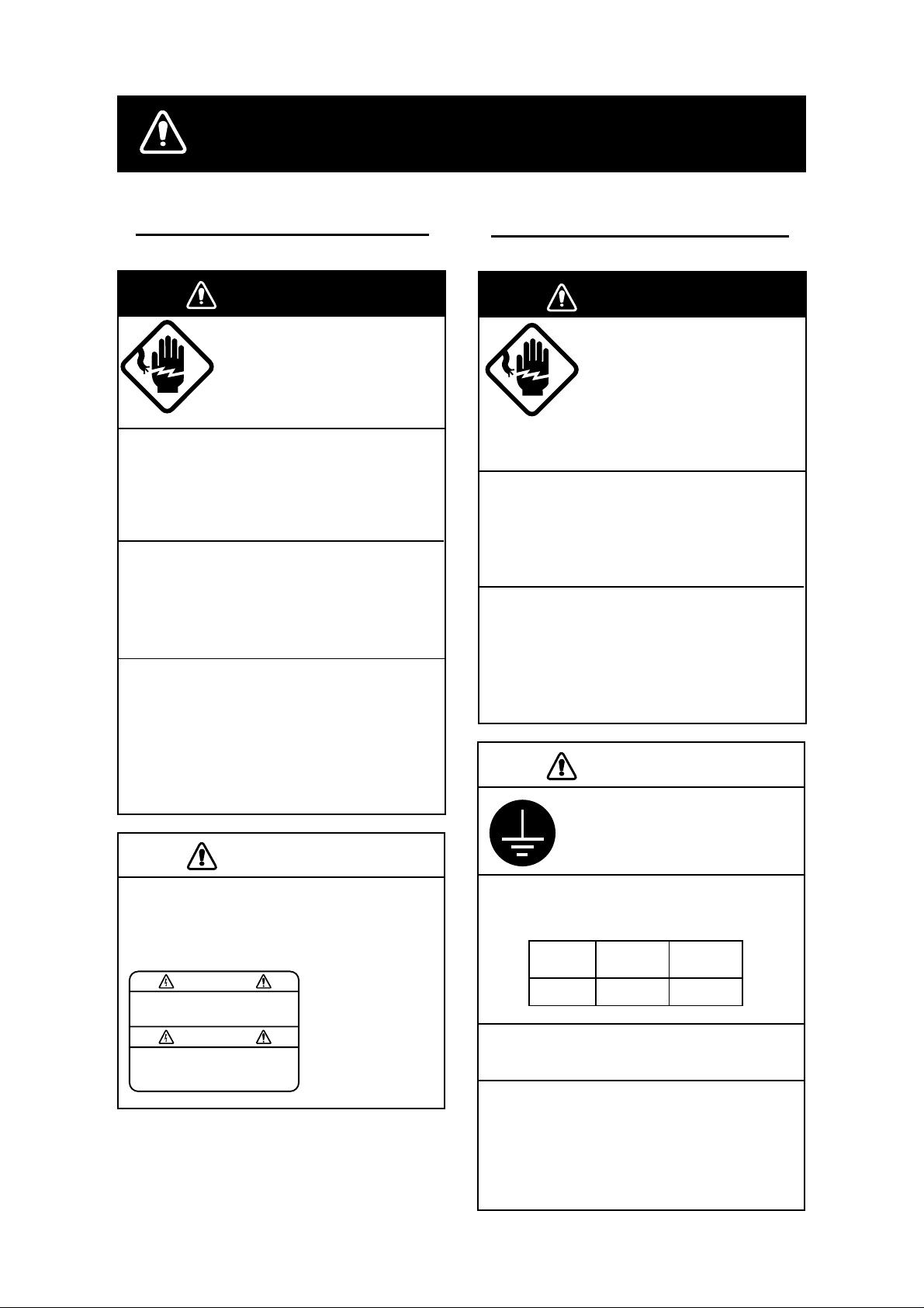
SAFETY INSTRUCTIONS
Safety Instructions for the Operator
WARNING
Do not open the equipment.
Only qualified personnel
should work inside
the equipment.
Do not disassemble or modify the
equipment.
Fire, electrical shock or serious injury can
result.
Use the proper fuse.
Fuse rating is shown on the equipment.
Use of a wrong fuse can result in damage
to the equipment.
Immediately turn off the power at the
switchboard if the equipment is emitting
smoke or fire.
Safety Instructions for the Installer
WARNING
Do not open the cover
unless totally familiar with
electrical circuits and
service manual.
Improper handling can result
in electrical shock.
Turn off the power at the switchboard
before beginning the installation.
Fire or electrical shock can result if the
power is left on.
Do not install the equipment where it
may get wet from rain or water splash.
Water in the equipment can result in fire,
electrical shock or damage to the equipment.
Continued use of the equipment can cause
fire or electrical shock. Contact a FURUNO
agent for service.
CAUTION
A warning label is attached to the
equipment. Do not remove the label.
If the label is missing or damaged,
contact a FURUNO agent or dealer.
WARNING
To avoid electrical shock, do not
remove cover. No user-serviceable
parts inside.
Name: Warning Label (1)
Type: 03-129-1001-1
Code No.: 100-236-741
CAUTION
Ground the equipment to
prevent mutual interference.
Observe the following compass safe
distances to prevent interference to a
magnetic compass:
Standard Steering
compass compass
MU-200C
Locate the MU-200C out of direct sunlight for optimum viewing.
When lifting the display unit, hold it
together with the cover.
Grasping by the cover alone may allow
the display unit to fall, resulting in
possible injury or damage to the equipment.
2.5 m 1.4 m
i
Page 4

TABLE OF CONTENTS
FOREWORD.........................................................................................................iii
SYSTEM CONFIGURATION................................................................................iv
EQUIPMENT LISTS ..............................................................................................v
INSTALLATION ................................................................................................1
1
1.1 Installing the Display Unit ................................................................................................1
2 WIRING.............................................................................................................4
2.1 Wiring External Equipment ..............................................................................................4
3 ADJUSTMENTS ...............................................................................................7
3.1 Picture Adjustment...........................................................................................................7
3.2 RGB Adjustment..............................................................................................................9
3.3 Brilliance..........................................................................................................................9
4 OPERATION...................................................................................................10
5 MAINTENANCE, TROUBLESHOOTING.......................................................11
5.1 Maintenance.................................................................................................................. 11
5.2 Troubleshooting.............................................................................................................12
APPENDIX.......................................................................................................AP-1
Parts Location .................................................................................................................AP-1
Parts List .........................................................................................................................AP-2
Interconnection Diagram .................................................................................................AP-3
Modification for Switching from Landscape to Portrait Orientation ...................................AP-4
SPECIFICATIONS...........................................................................................SP-1
PACKING LIST
OUTLINE DRAWING
INTERCONNECTION DIAGRAM
SCHEMATIC DIAGRAMS
ii
Page 5

FOREWORD
A Word to the Owner of the MU-200C
FURUNO Electric Company thanks you for purchasing the MU-200C 20.1” Multi-Purpose
LCD Display. We are confident you will discover why the FURUNO name has become
synonymous with quality and reliability.
For over 50 years FURUNO Electric Company has enjoyed an enviable reputation for
quality and reliability throughout the world. This dedication to excellence is furthered by our
extensive global network of agents and dealers.
Your equipment is designed and constructed to meet the rigorous demands of the marine
environment. However, no machine can perform its intended function unless properly
installed and maintained. Please carefully read and follow the operation, installation and
maintenance procedures set fort h in this manual.
We would appreciate feedback from you, the end-user, about whether we are achieving our
purposes.
Thank you for considering and purchasing FURUNO.
Features
•
Main or remote display for radars, video sound ers, sonars and pos ition-f ixing equipm ent.
Compatible equipment: FR-2105B Series, FCV-1200 series, FCV-1500 series, FSV-24,
GD-280/360/380, etc.
•
High resolution display of 1280 X 1024 dot (SXGA), 640 X 480 dot (VGA)
•
Brightness of more than 200 cd/m2 for comfortable viewing day and night
•
Landscape or portrait orientation
•
Wide viewing angle of 160° for observation b y more than one person
iii
Page 6
v
SYSTEM CONFIGURATION
RGB
100 - 240 VAC
NMEA 0183
Equipment Category: Protected
Radar, Video Plotter,
Navigator, Video Sounder,
Scanning Sonar, etc.
Control unit of
Video Sounder
(e.g., FCV-1200 series)
Navigator (GPS, etc.)*
* = When using the FCV-1200 series,
NMEA 0183 data may be input to the
processor unit of the echo sounder,
via the MU-200C.
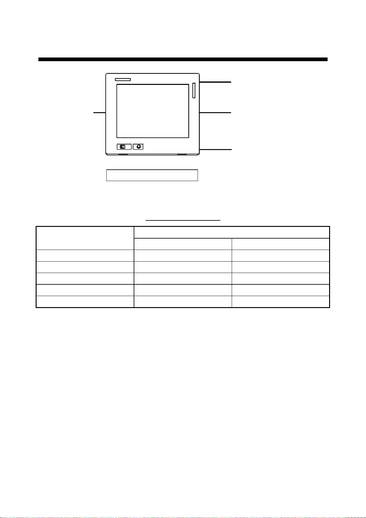
Connect able equipment
MU-200C Display Unit Type
Equipment
Landscape Portrait*
FR-210 5B Seri es Yes No
FCV-1200 Series Yes Yes (Modification required)
FCV-1500 Series No Yes (Modification required)
FSV-24 Yes No
GD/GP-280/380/680 Yes No
*=Display should not be vi ewed wit h polarized sunglasses.
i
Page 7
v
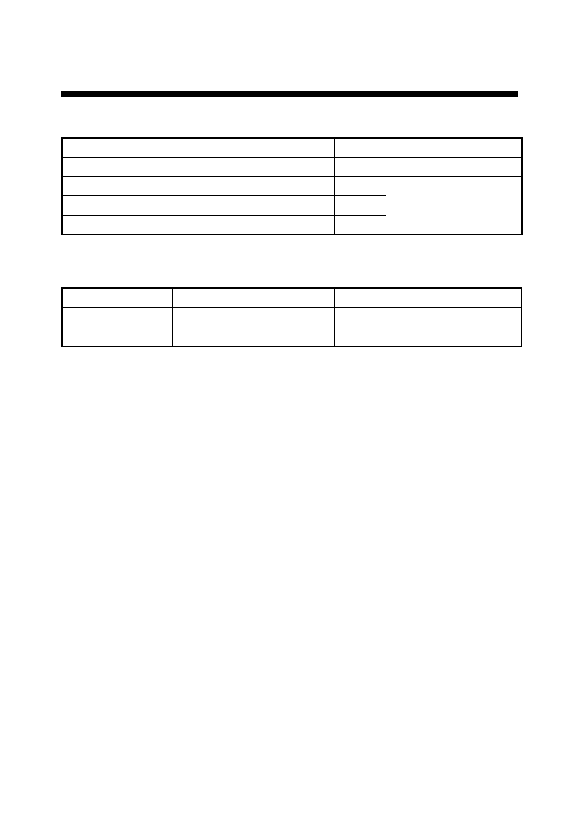
EQUIPMENT LISTS
Standard supply
Name Type Code No. Qty Remarks
Display Unit MU-200C − 1
Spare Parts SP10-02803 001-414-950 1 set
Installation Materials CP10-05001 001-414-550 1 set
Accessories FP10-02501 001-414-490 1 set
Optional equipment
Name Type Code No. Qty Remarks
Hood (Landscape) FP10-02612 001-414-770
Hood (Portrait) FP10-02613 001-414-790
1
1
See list at end of manual
Page 8

This page is intentionally left blank .
Page 9
1 INSTALLATION
Refer to the outline drawing at the end of the manual for mounting dimensions.
Note: The LCD is made of glass. Handle it with care.
1.1 Installing the Display Unit
The display unit is designed to be flush mounted in a console. When selecting a mounting
location, keep in mind the following points:
• Locate the unit out of direct sunlight.
• Select a location where the display can be easily viewed and the controls can be easily
operated.
• Leave sufficient space around the unit for servicing and maintenance. See the outline
drawing for recommended servicing space.
• The unit weighs 50.7 lbs (23 kg). Be sure the mounting location is strong enough to
support the weight of the unit.
• Locate the unit away from areas subject to water splash and rain.
Procedure
1. Using the paper template supplied in the installation materials, make a cutout in the
mounting location. (Modification of the LCD may be necessary depending on equipment
used. See the table on page iv and “Modification for Switching from Landscape to
Portrait Orientation” in the Appendix for details.)
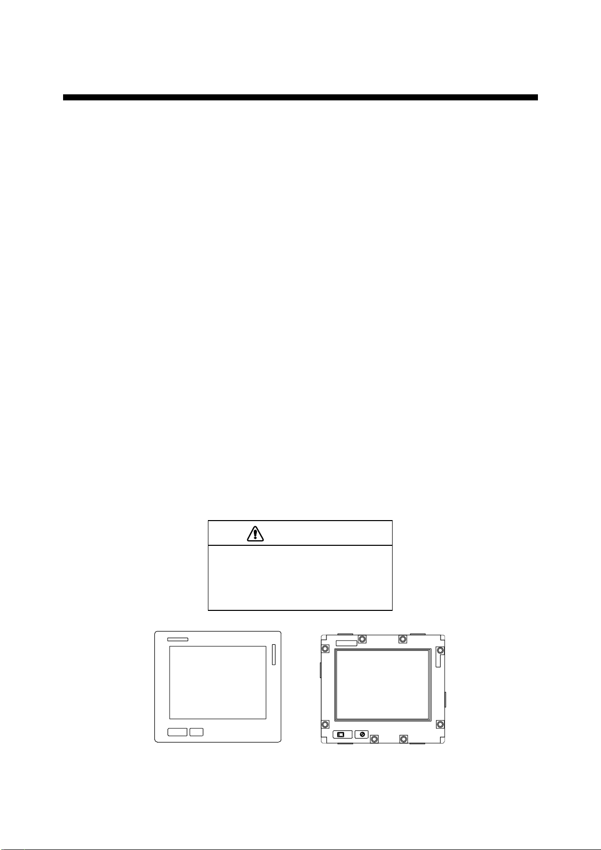
2. Pull the display unit cover toward you to detach it.
CAUTION
Hold the cover and display unit
together.
The display unit may fall if only the cover
is held.
Cover Display Unit
Display unit and cover
1
Page 10
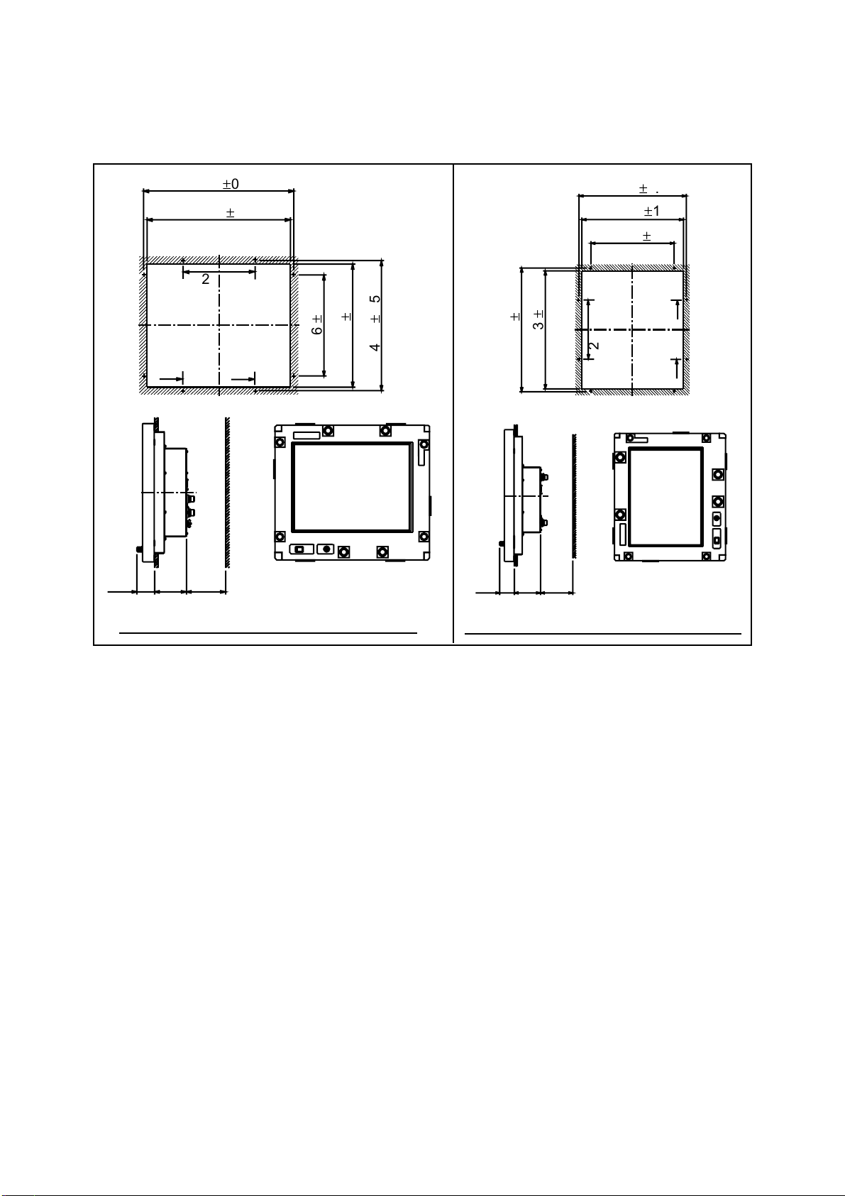
3. Fasten the display unit to the mounting location with eight tapping screws (5X30).
Note: Hex head bolts may also be used to fasten the display unit. However, their length
must be at least 30 mm.
45
501 ±0.5
483 ±1
226
49 113
115
100
0.5
±
346
1
±
422
Unit: mm
0.5
±
440
45
0.5
±
501
115
1
±
483
100
440 ±0.5
422 ±1
346 ±0.5
226
49 113
Unit: mm
Mounting dimensions for landscape orientation Mounting dimensions for portrait orientation
Mounting dimensions
4. Reattach the cover.
5. For the portrait model only, attach the FURUNO logo seal (supplied) at the top left
corner. (Remove the logo seal at the bottom left corner.)
2
Page 11
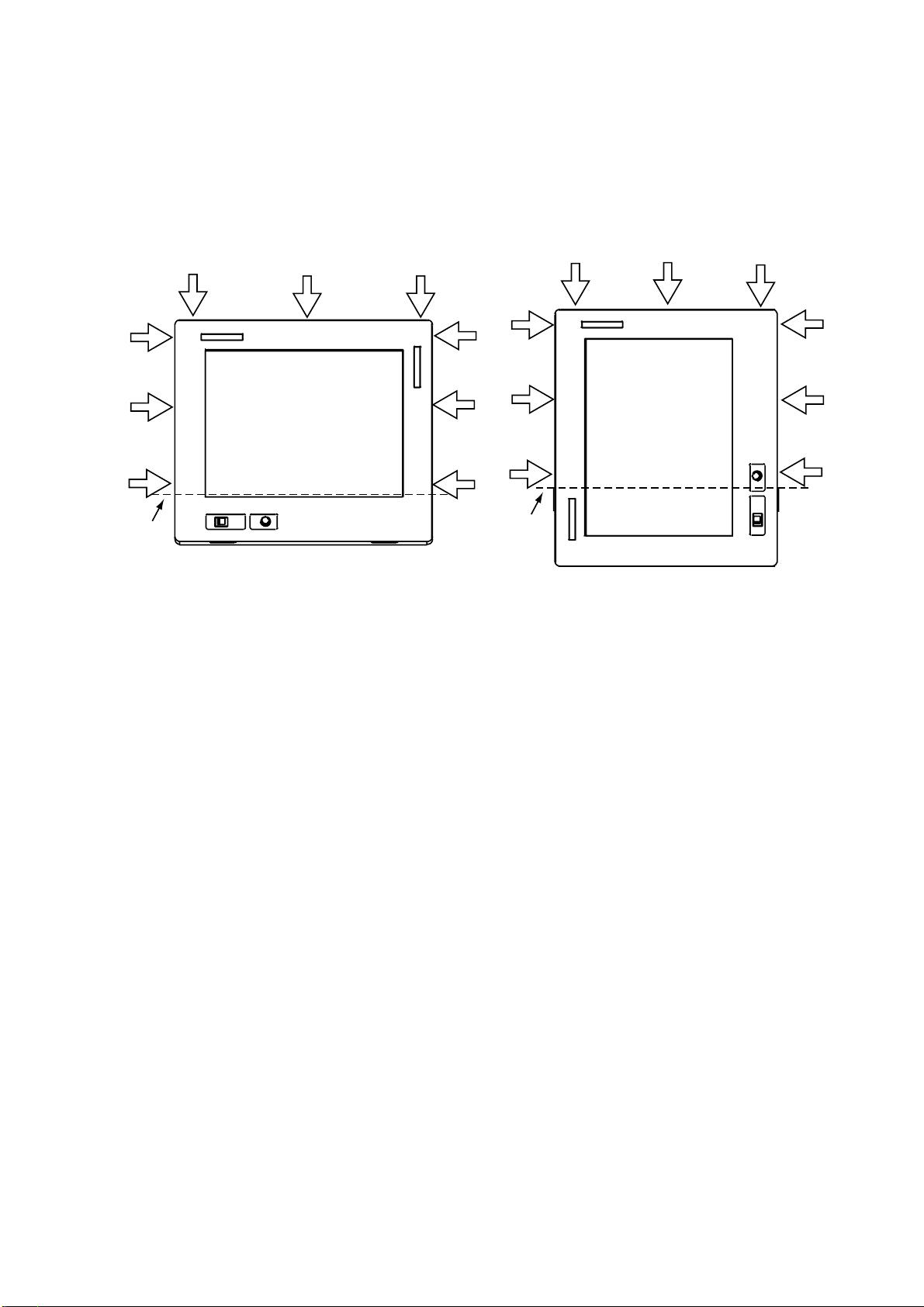
1.1.1 Hood (option)
A hood (portrait or landscape) is optionally available. Attach it to the display unit with Velcro
tape as shown below.
1. Attach nine sets of Velcro tape to the display unit at the locations shown below, in as
straight as possible.
Attach
in line.
Display unit, how to attach Velcro tapes
2. Attach the hood to the display unit.
Attach
in line.
3
Page 12
2 WIRING
2.1 Wiring External Equipment
Connect external equipment to the MU-200C by referring to the drawings in this section. A
cable with connector at both ends is provided to connect equipment. For details, see the
interconnection diagram on page S-1.
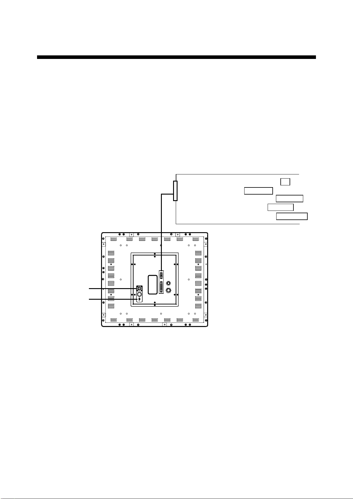
General-purpose monitor
To use the MU-200C as a general-purpose monitor, connect equipment with a mini D-SUB
15P connector. In this case do not connect a navigator to the NMEA port. Nav data is output
through the D-SUB 25P connector.
FR-2105B Series: PROCESSOR UNIT J2
Mini D-SUB
15P
FSV-24: DISPLAY UNIT MONITOR
FCV-1200 Series: INTERFACE UNIT RGB OUT
FCV-1500 Series: DISPLAY UNIT DISPLAY
GP/GD-280/380/680: DISPLAY UNIT EXT VIDEO
100 - 240 VAC
Ground
Terminal
Display unit, rear view, wiring using general-purpose video cables
Note: Use the following cable or the equivalent:
Mini D-SUB 15P: EVNPS05-50 ft, male-female, (max. 15 m)
Manufacturer: BlackBox Japan
4
Page 13

Connecting FCV-1200 series
Using the cables designated below (or equivalent) to connect the FCV-1200 series makes
the interface unit of the FCV-1200 series unnecessary. The mini D-SUB 15 P connector
cannot be used to connect the FCV-1200 series.
Navigator
Cable type
100 - 240 VAC
06S4078
Ground
Terminal
Cable type
MJ-A10SPF0002-015
FCV-1200 Series:
PROCESSOR UNIT CN1
FCV-1200 Series:
CONTROL UNIT CONT
Display unit, rear view, wiring using specialty cables
Notes on wiring
• The cover of the D-SUB connector of the cable 06S4078 may be removed to pass the
cable through tubing, bulkhead, etc. Use vinyl tape to bind connector wiring and rubber
cover. This allows the cable to be passed through a hole having a diameter of 30 mm.
• Attach connector SRCN6A13-3S (supplied in installation materials) to the power cable
(cable DPYC-1.5 (Japan Industrial Standard) or equivalent).
Sheath
Armor
Armor
Armor
2 cm
3mm
Solder Side
Screw
Clamp
Connector Housing
Attaching connector SRCN6A13-3S
Tighten
set screw
21
3
Connect to
"1" and "2".
1: AC (L: Live line)
2: AC(N: Neutral line)
Vinyl
sheath
Armor
Conductor
S = 1.5 mm
f
= 1.56 mm
Sectional view of cable DPYC-1.5
2
How to attach connector SRCN6A13-3S; sectional view of power cable DPYC-1.5
5
Page 14

• Cable 06S4078 is of waterproof construction, however, the MU-200C is not waterproof
(specification IPX0). Therefore, remove rubber cover and fixing metal from the display
side of the cable.
Remove fixing metal.
Remove rubber cover.
D-SUB connector
6
Page 15

3 ADJUSTMENTS
Controls for adjustment of the picture are provided on the rear of the display unit. Open the
small cover to access the controls.
12
3
GND
100-240 VAC
50-60 Hz
R1
J16
R2
R3
J17
J18
R1
R2
R3
EXTBILL
BRILL
BRTP
G
B
B
S1
S2
S3
S4
SEL
UP
DOWN
RESET
Controls for adjustment
of picture (remove cover
to access)
POWER
3A
S1 S2 S3 S4
J16 J17 J18
131313
DATA/VIDEO IN
CONT
NMEA
Rear panel
3.1 Picture Adjustment
Contrast and picture are adjusted with
[S1]: Opens OSD (On Screen character Display) menu; selects menu items. See the next
page for description of OSD menu.
[S2]: Increases setting.
[S3]: Decreases setting.
[S4]: Initializes setting.
About the picture adjustment buttons
• [S2]/[S3] may be pressed and held down to increase/decrease setting more rapidly.
• Press buttons within ten seconds of each other. Otherwise, the previous condition is
restored.
• Press the [S4] button more than two seconds to initialize setting.
7
Page 16

OSD menu
[S1]
BRIGHTNESS
CONTRAST
RGB
>>
These items are
for reference only;
they cannot be
adjusted.
i
COLOR
RGB
[S3]
GAMMA
[S2]
A.G.C.
RESOLUTION
H.SYNC
V.SYNC
SIGNAL SOURCE
>>
RGB
>>
1280x1024
64. 1kHz
60. 1 Hz
ANALOG
i
H.POSITION
[S3]
[S2]
i
[S3]
[S2]
V.POSITION
SIZE
FOCUS
AUTO ADJUST
OSD POSITION
LANGUAGE
ALL RESET
>>
i
[S3][S2]
i
>>
OSD menu
Description of OSD menu
Description of OSD menu
No. Item Description
1 Brightness Not used.
2 Contrast Adjusts LCD contrast.
3 Color Adjusts black level to match input signal level.
4 Gamma Adjusts tone characteristics.
5 A. G. C. (Auto Gain Control) Adjusts auto gain to match amplitude of input signal level.
6 H. Position Adjusts horizontal position.
7 V. Position Adjusts vertical position.
8 Size Adjusts dot clock frequency to match input signal.
9 Focus Adjusts clock delay.
10 Auto Adjust Automatically adjusts position, size and clock.
11 OSD Position Adjusts menu position.
12 Language
Chooses menu language from English, German, French
and Spanish.
13 All Reset Restores default settings for items 1-9, 11 and 12.
14 Information
Displays input signal information: Input signal resolution,
horizontal synchronization signal and vertical
synchronization signal frequencies.
8
Page 17

3.2 RGB Adjustment
Color may be adjusted with the following potentiometers on the rear panel. Turn the
potentiometer clockwise to increase color.
Model Potentiometer Setting
FCV-1200 Series Default setting
FSV-24, GD/GP-280/380/680,
FCV-1500 Series, FR-2105B Series
R1: Red
R2: Green
R3: Blue
Fully clockwise
3.3 Brilliance
Brilliance of the display unit can be adjust ed from the control unit of the FCV-1200 series by
setting jumper block J17 as below.
J17: Brilliance control circuit selection
1-2: Brilliance is adjusted from the MU-200C (default setting)
2-3: Brilliance is adjusted from the control unit of the FCV-1200 series
Note: Do not change the setting of the J16 or J18. The default setting for both is “1-2”.
S1 S2 S3 S4
R1
J16
EXTBILL
J17
J16 J17 J18
131313
R2
R3
Jumper blocks
J18
R1
R2
R3
BRILL
BRTP
G
B
B
S1
S2
S3
S4
SEL
UP
DOWN
RESET
9
Page 18

4 OPERATION
FURUNO
BRILLIANCE ControlLED
POWER
Switch
Display unit
POWER switch: Turns the power on/off. The LED lamp lights in green when the unit
is turned on and goes off when the unit is turned off.
To turn the MU-200C on and off from the control unit of a video
sounder such as the FCV-1200 series, turn on the POWER switch
of the MU-200C. Note that with the MU-200C t urned on and the
FCV-1200 turned off the LED on the MU-200C lights in red. This
means that weak current is flowing to the MU-200C. To turn off the
power completely, turn off the MU-200C.
BRILLIANCE control: Adjusts display brilliance. In some instances brilliance is controlled
from the equipment connected (for example, FCV-1200 series).
LED: Shows display status:
Green: Display on
Red: Power save
10
Page 19

5 MAINTENANCE,
TROUBLESHOOTING
WARNING
ELECTRICAL SHOCK HAZARD
Do not open the equipment.
Only qualified personnel
should work inside the
equipment.
5.1 Maintenance
Routine maintenance
Regular maintenance is im portant for good performance. Check the following on a regular
basis to keep the equipment in good operat ing condition.
• Check that the connectors at the rear of the display unit are t ightly fastened.
• Check the ground wire and ground terminal for rust. Clean if necessary. Confirm that the
ground wire is tightly fastened.
• Do not use chemical cleaners to clean any part of the display unit – they can remove
paint and markings.
• Wipe the LCD carefully to prevent scratching, using t issue paper and an LCD cleaner.
To remove dirt or salt deposits, use an LCD cleaner, wiping slowly with tissue paper so
as to dissolve the dirt or salt. Change paper frequently so the salt or dirt will not scratch
the LCD. Do not use solvents such as thinner, acetone or benzene for cleaning.
Fuse replacement
The 3 A 250 V fuse on the rear panel protects the equipment from internal fault and
overvoltage. If the fuse blows, find the cause before replacing it. If the fuse blo ws again
after replacement, request service.
WARNING
Use the proper fuse.
Use of a wrong fuse can cause fire or
damage to the equipment.
11
Page 20

5.2 Troubleshooting
The table below provides troubleshooting procedures to use when no picture appears. If
you cannot restore the picture, do not attempt to check inside the equipment – there are no
user serviceable parts inside. Refer any work to a qualified technician.
Troubleshooting table
Reason for no picture Remedy
Ship’s mains voltage is too high. Check voltage.
Fuse has blown. Replace fuse.
Cable between MU-200C and external
equipment has loosened.
Power cable has loosened. Refasten cable.
Refasten cable.
12
Page 21

A
APPENDIX
Parts Location
SCB
Board
10P6879
CONE
Board
10P6877
POWER
Assy.
Display unit, rear cover removed
VRB Board
10P6878
LCD I/F
Board
Inverter
for Backlight
LCD
Note: LCD assy. manufactured by NEC (Nippon Electronics Corporation).
Display unit, rear cover removed, LCD assembly
P-1
Page 22

A
Parts List
Y
This equipment contains complex modules in which fault diagnosis and repair down to
component level are not practical (IMO A.694(17)/8.3.1. Only some discrete components
are used. FURUNO Electric Co. Ltd. believes identifying these components is of no value
for shipborne maintenance; therefore, they are not listed in this manual. Major modules can
be located on the parts location photo on page AP-1.
F U R U N O
ELECTRICAL PARTS LIST Ref.Dwg. Page
Dec. 2001 Blk.No.
SYMBOL TYPE CODE No. REMARKS SHIPPABLE
PRINTED CIRCUIT BOARD
10P6878, VRB 001-414-610 X
10P6879, SCB 001-414-620 X
10P6877, CONE 001-414-630 X
ASSEMBLY
MU-200C 001-414-680 LCD X
MU-200C 001-414-650 FILTER X
Model MU-200C
Unit MU-200C
DISPLAY UNIT
ASSEMBL
P-2
Page 23

A
Interconnection Diagram
J1
For control section;
video, control signal
J2
Video signal
J3
Operation section;
control signal
J4
For navigator
J5
AC input
MXB1206-35
CONE Board 10P6877
Display control signal
Video signal
LCD power
J5
AC input
J13
Brillliance adj.
J11
AC power, switch
Power for
backlight
inverter
J10
DC power
J6
J8
J7
J9
LCD I/F Board
CN1
Video signal
CN4
Power for LCD
CN5
Display control signal
CN7
Backlight control signal
CN201
Power for
backlight
Inverter for Backlight
CN202
Backlight
control
signal
J1
AC power
input
SCB
PWR SW
JW_S21RKK
LCD Panel
NL128102AC31-02A
Board
VRB
Board
J1
Brilliance adj.
FAW128R3
+12V
P-3
Page 24

A
Modification for Switching from Landscape to Portrait Orientation
To use the MU-200C with the FCV-1200 series, it is necessary to turn the LCD assembly
180°.
1. Place the display unit on a workbench with the LCD side down.
2. Unfasten ten screws, four sets of connector spacers, and two nuts of waterproofing
connectors to remove the cover near the power section and connectors.
POWER Section
CONE Board 10P6877
Display unit, rear view
P-4
Page 25

A
3. Unfasten 14 screws to detach the rear cover.
Display unit, rear view
4. Release the cables from the clamps marked with the arrows in the figure below.
J9
J8
J6
J7
* Do not release the cable from the clamp near the power assy. chassis.
J10
J11
J5
J13
*
*
Power section/CONE board assembly 10P6877
P-5
Page 26

A
5. Unfasten the four screws marked with the arrows in the figure below. Slide the CONE
board assy. (10P6877) in the direction of the largest white arrow in the figure below to
dismount it.
Power section/CONE board assy. (10P6877)
6. Disconnect the connectors marked with arrows, four power switch tab terminals and
cable from CK clamp.
Power assembly
P-6
Page 27

A
7. Unfasten eight screws marked with arrows in the figure below.
POWER
Chassis
Do not loosen screws marked in red.
Doing so will allow dust to enter
between the LCD and filter.
P-7
Page 28

A
8. Turn the LCD assembly 180°.
9. Turn the power chassis 180°.
LCD assembly
10. Fasten the LCD assy. with the eight screws removed at step 7.
11. Fix the CONE Board (10P6877) with the four screws removed at step 5. (Torque: 0.78
±0.08 Nm; 8 ±0.08 kgm)
P-8
Page 29

A
12. Connect all connectors on the CONE Board (10P6877).
J8
J6
J9
J10
J7
J11
J5
J13
Pass cable from
J13 through
clamp.
Pass cable from
J8,J9 through
clamp.
Pass cable from
J6 through
clamp.
Pass cable from
J7 through
clamp.
CONE Board (10P6877)
13. Fix the cable marked with a white arrow in the figure below with the clamp. Connect the
power connector (marked with gray arrow) to J1 on the pcb 10P3879: 1, Brown; 3,
Orange; 4, Purple, 6, White.
Display unit, rear view
P-9
Page 30

A
14. Fix the rear cover with 14 screws (M4X8). (Torque: 1.47 ±0.15 Nm; 15 ±1.5 kgm)
15. Temporarily fasten the cover near the power section/connectors with 10 screws (M3X8).
16. Fix four connector spacers. (Torque: 0.39 ±0.04 Nm; 4 ±0.4 kgm)
17. Fasten inner six screws (M3X8) for the cover near power section/connectors. (Torque:
0.78 ±0.08 Nm; 8 ±0.8 kgm)
18. Fasten two waterproofing nuts. (Torque: 0.76 ±0.02 Nm; 7.8 ±0.2 kgm)
19. Fasten the remaining four screws for the cover near the power section/connectors.
(Torque: 0.78 ±0.08 Nm; 8 ±0.8 kgm)
20. Attach FURUNO logo seal to top left corner of the display unit.
P-10
Page 31

SPECIFICATIONS OF MULTI-PURPOSE LCD DISPLAY
MU-200C
1. GENERAL
1.1 Display 20.1 inch color LCD, 399.4 x 319.5 mm
1.2 Brightness 200 cd/m2 or more
1.3 Resolution VGA (640 x 480), SXGA (1280 x 1024)
1.4 Viewing Angle 160° (left/right 80°, up/down 80°)
1.5 Input Signal RGB: 0.7 Vp-p to 3.0 Vp-p, Synchronization: TTL level
2. POWER SUPPLY
2.1 Rated Voltage 100-240 VAC: 1.2-0.6 A, 1 phase, 50-60 Hz
3. ENVIRONMENTAL CONDITION
3.1 Ambient Temperature 0°C to +50°C
3.2 Relative Humidity 95% at 40°C
3.3 Waterproofing IPX0
3.4 Vibration IEC 60945
4. COATING COLOR
4.1 Main Unit N3.0
SP - 1 E2026S01C
Page 32

PACKING LIST
A - 1
PACKING LIST
PACKING LISTPACKING LIST
MU-200C
MU-200C
MU-200CMU-200C
10CR-X-9851 -2
1/1
N A M E
ユニット
ユニット UNIT
ユニットユニット
20.1型カラーLCD表示器
MULTI-PURPOSE LCD DISPLAY
予備品
予備品 SPARE PARTS
予備品予備品
ヒューズ
FUSE
付属品
付属品 ACCESSORIES
付属品付属品
ロゴシート
LOGO SEAL
工事材料
工事材料 INSTALLATION MATERIALS
工事材料工事材料
コネクタ(SRCN)
CONNECTOR
その他工材
その他工材 OTHER INSTALLATION MATERIALS
その他工材その他工材
装備用型紙
UNIT
UNITUNIT
SPARE PARTS SP10-02803
SPARE PARTSSPARE PARTS
ACCESSORIES FP10-02501
ACCESSORIESACCESSORIES
INSTALLATION MATERIALS CP10-05001
INSTALLATION MATERIALSINSTALLATION MATERIALS
OTHER INSTALLATION MATERIALS
OTHER INSTALLATION MATERIALSOTHER INSTALLATION MATERIALS
O U T L I N E
DESCRIPTION/CODE №
MU-200C-H-AC
000-012-619
FGMB 3A 250V
000-145-721
10-075-1052-0
100-294-900
SRCN6A13-3S
000-508-665
10-075-1171-0
SP10-02803
SP10-02803SP10-02803
FP10-02501
FP10-02501FP10-02501
CP10-05001
CP10-05001CP10-05001
Q'TY
1
2
1
1
TEMPLATE
1
100-294-600
(略図の寸法は、参考値です。 DIMENSIONS IN DRAWING FOR REFERENCE ONLY.)
(略図の寸法は、参考値です。 DIMENSIONS IN DRAWING FOR REFERENCE ONLY.)
(略図の寸法は、参考値です。 DIMENSIONS IN DRAWING FOR REFERENCE ONLY.)(略図の寸法は、参考値です。 DIMENSIONS IN DRAWING FOR REFERENCE ONLY.)
Page 33

Page 34

Page 35

Page 36

Page 37

Page 38

Page 39

 Loading...