

Page 1

OPERATOR'S MANUAL
取扱説明書
MONITOR UNIT
表示部
MODEL
MU-190
www.furuno.com
Page 2
(Elemental Chlorine Free)
The paper used in this manual
is
elemental chlorine free.
・ 機器の修理・使用方法等に関するお問い合わせは、お買い上げの販売店・代理店、最寄りの
当社支店・営業所あてへお願いします。
・
FURUNO Authorized Distributor/Dealer お問い合わせは
本書の無断複写複製(コピー)は特定の
場合を除き、当社権利侵害になります。
Printed in Japan
Pub. No. OMC-44670-A1
( YOTA) MU-190
A
: M AY 2011
A1
: JUL. 5, 2011
Page 3
IMPORTANT NOTICES
General
• This manual has been authored with simplified grammar, to meet the needs of international users.
• The operator of this equipment must read and follow the descriptions in this manual. Wrong operation or maintenance can cancel the warranty or cause injury.
• Do not copy any part of this manual without written permission from FURUNO.
• If this manual is lost or worn, contact your dealer about replacement.
• The contents of this manual and equipment specifications can change without notice.
• The example screens (or illustrations) shown in this manual can be different from the screens
you see on your display. The screens you see depend on your system configuration and equipment settings.
• Save this manual for future reference.
• Any modification of the equipment (including software) by persons not authorized by FURUNO
will cancel the warranty.
• All brand and product names are trademarks, registered trademarks or service marks of their
respective holders.
How to discard this product
Discard this product according to local regulations for the disposal of industrial waste. For disposal
in the USA, see the homepage of the Electronics Industries Alliance (http://www.eiae.org/) for the
correct method of disposal.
How to discard a used battery
Some FURUNO products have a battery(ies). To see if your product has a battery, see the chapter
on Maintenance. Follow the instructions below if a battery is used. Tape the + and - terminals of
battery before disposal to prevent fire, heat generation caused by short circuit.
In the European Union
The crossed-out trash can symbol indicates that all types of batteries
must not be discarded in standard trash, or at a trash site. Take the
used batteries to a battery collection site according to your national
legislation and the Batteries Directive 2006/66/EU.
In the USA
The Mobius loop symbol (three chasing arrows) indicates that Ni-Cd
and lead-acid rechargeable batteries must be recycled. Take the used
batteries to a battery collection site according to local laws.
In the other countries
Ni-Cd Pb
Cd
There are no international standards for the battery recycle symbol. The number of symbols can
increase when the other countries make their own recycle symbols in the future.
i
Page 4
WARNING
WARNING
CAUTION
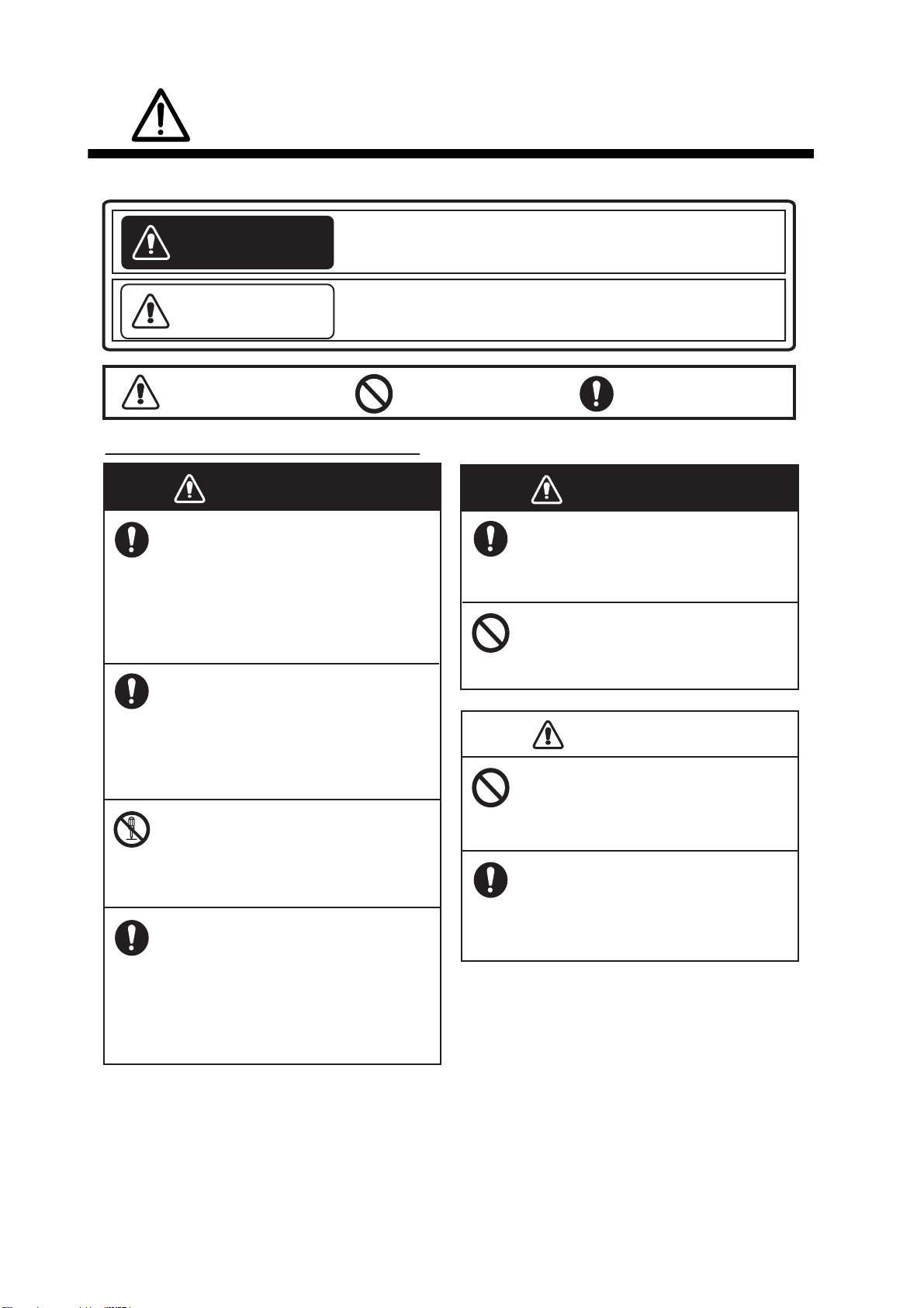
SAFETY INSTRUCTIONS
Read these safety instructions before you operate the equipment.
WARNING
CAUTION
Warning, Caution
Indicates a condition that can cause death or serious
injury if not avoided.
Indicates a condition that can cause minor or moderate
injury if not avoided.
Prohibitive Action
Safety Instructions for the Operator
WARNING
Immediately turn off the power at the
switchboard if water leaks into the
equipment or something is dropped
into the equipment.
Continued use of the equipment can cause
fire or electrical shock. Contact a FURUNO
agent for service.
Immediately turn off the power at the
switchboard if the equipment is
emitting smoke or fire.
Continued use of the equipment can
cause fire or electrical shock. Contact a
FURUNO agent for service.
WARNING
Use the proper fuse.
Use of a wrong fuse can cause fire or
damage to the equipment.
Do not place any object near the
exhaust or intake vent.
Fire may result.
Do not connect/disconnect the signal
cable while turning the power on.
CAUTION
Mandatory Action
Do not disassemble or modify the
equipment.
Fire, electrical shock or serious injury
can result.
Turn off the power immediately if you
feel the equipment is behaving
abnormally.
Turn off the power at the switchboard if
the equipment becomes abnormally
warm or is emitting odd noises. Contact
a FURUNO dealer or agent for advice.
The unit may be damaged.
Handle the LCD monitor with care.
The face of the LCD monitor is made
of glass.
glass breaks.
ii
Injury may result if the
Page 5
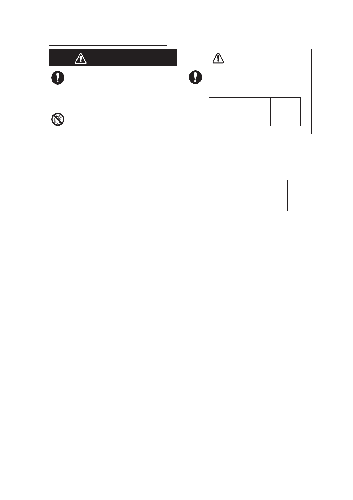
Safety Instructions for the Installer
WARNING
CAUTION
About the TFT LCD
SAFETY INSTRUCTIONS
WARNING
Turn off the power at the switchboard
before beginning the installation.
Fire or electrical shock can result if the
power is left on.
Do not install the equipment where it
may get wet from rain or water splash.
Water in the equipment can result in fire,
electrical shock or damage to the
equipment.
About the TFT LCD
About the TFT LCD
The TFT LCD is constructed using the latest LCD techniques, and displays
99.99% of its pixels. The remaining 0.01% of the pixels may drop out or
blink, however this is not an indication of malfunction.
Observe the following compass safe
distances to prevent interference to a
magnetic compass:
CAUTION
Standard
compass
MU-190
1.65 m 1.05 m
Steering
compass
iii
Page 6

TABLE OF CONTENTS
Note: This manual contains both English and Japanese instructions. The Installation
Materials, Outline Drawings, and Interconnection Diagram are located at the back of this
manual.
FOREWORD ................................................................................................................. v
SYSTEM CONFIGURATION ....................................................................................... vi
EQUIPMENT LISTS.................................................................................................... vii
1. MOUNTING, WIRING............................................................................................. 1
1.1 Preparation................................................................................................................. 1
1.2 Flush Mount, Fixed at Front ....................................................................................... 2
1.3 Flush Mount, Fixed at Front, with Hood ..................................................................... 3
1.4 Flush Mount, Fixed at Rear........................................................................................ 5
1.5 Flush Mount, Fixed at Rear, with Hood...................................................................... 7
1.6 Tabletop Mount .......................................................................................................... 8
1.7 Flush Mount a Series Side by Side.......................................................................... 10
1.8 Wiring .......................................................................................................................11
2. ADJUSTMENTS................................................................................................... 12
2.1 Installation Settings .................................................................................................. 12
2.2 RGB/DVI Setting (For Non-SOLAS)......................................................................... 14
2.3 Video Composite Signal Setting (For Non-SOLAS)................................................. 16
2.4 The Menu Window Setting (For Non-SOLAS) ......................................................... 17
2.4.1 How to adjust the menu window ....................................................................... 17
2.4.2 How to change the signal name ....................................................................... 18
3. OPERATION ........................................................................................................ 19
3.1 Controls.................................................................................................................... 19
3.2 How to Turn the Power On/Off................................................................................. 19
3.2.1 Turn the power on/off........................................................................................ 19
3.2.2 Unlock the key operation .................................................................................. 20
3.3 How to Adjust the Display Brilliance......................................................................... 20
3.4 How to Select the Source for Main Picture .............................................................. 21
3.5 How to Display the PIP Window............................................................................... 21
3.6 SYSTEM Menu ........................................................................................................ 21
3.6.1 How to set the auto dimmer .............................................................................. 21
3.6.2 How to clear the memory.................................................................................. 22
4. MAINTENANCE, TROUBLESHOOTING............................................................. 23
4.1 Maintenance............................................................................................................. 23
4.2 Troubleshooting ....................................................................................................... 24
4.3 Parts Location and Parts List ................................................................................... 24
SPECIFICATIONS .................................................................................................. SP-1
INSTALLATION MATERIALS .................................................................................. A-1
OUTLINE DRAWINGS.............................................................................................. D-1
INTERCONNECTION DIAGRAM ..............................................................................S-1
Declaration of Conformity
iv
Page 7
FOREWORD
A Word to the Owner of the MU-190
FURUNO Electric Company thanks you for purchasing the MU-190 19” Monitor Unit. We are confident you will discover why the FURUNO name has become synonymous with quality and reliability.
For over 60 years FURUNO Electric Company has enjoyed an enviable reputation for quality and
reliability throughout the world. This dedication to excellence is furthered by our extensive global
network of agents and dealers.
Your equipment is designed and constructed to meet the rigorous demands of the marine environment. However, no machine can perform its intended function unless properly installed and
maintained. Please carefully read and follow the operation, installation and maintenance procedures set forth in this manual.
We would appreciate feedback from you, the end-user, about whether we are achieving our purposes.
Thank you for considering and purchasing FURUNO.
Features
The main features of the MU-190 are as shown below.
• Selectable screen from RGB (1 port), Digital (2 ports) or Composite (1 port).
• Main or remote display for radars, video sounders, sonars, plotter. For the connectable equipment, see the SYSTEM CONFIGURATION on page vi.
• High resolution display of 1280 x 1024 (SXGA)
• Automatic brilliance adjustment by the light sensor.
• Picture-in-picture function
• Power on/off automatically through the DVI signal.
Program
Program Name Version Date of Change
APR PROGRAM 2651020-01.xx May. 2011
FPGA PROGRAM 2651021-01.xx May. 2011
xx: minor change
You can see these program numbers on the [SYSTEM] menu (see section 3.6). To open the
[SYSTEM] menu, unlock the key operation (see paragraph 3.2.2).
Note: When you connect the monitor unit to FAR-21x7 series, FEA-2107 or FCR-21x7 series, lock
the key operation (see paragraph 3.2.2) after confirming the program numbers.
v
Page 8
SYSTEM CONFIGURATION
100-230 VAC
MONITOR UNIT
MU-190
RGB
DVI (2 ports)
VIDEO (NTSC/PAL)
RS-232C
Environmental category
MU-190: Protected from the weather
FSV-30/30S, etc.
FAR-21x7, FEA-2107, FCR-21x7, etc.
CCD camera, DVD recorder, etc.
FEA-2107, FCR-21x7, etc.
Connectable equipment
Equipment Resolution Signal
FCV-1200L/1200LM VGA* Analog RGB, via IF-8000
FSV-24/24S SXGA Analog RGB
FSV-30/30S SXGA Analog RGB
FSV-84/84L SXGA Analog RGB
FSV-85/85L SXGA Analog RGB
FCV-30 SXGA Analog RGB
FAR-21x7 SXGA DVI
FEA-2107 SXGA DVI
FCR-21x7 SXGA DVI
SVGA*
MFDBB (NAVnet 3D)
SXGA
DVIXGA*
Note 1: Landscape orientation only.
Note 2: *: When inputting VGA, SVGA or XGA, a circle may be displayed as an ellipse because
the aspect ratio differs (see "DISP MODE*" on page 15).
vi
Page 9
EQUIPMENT LISTS
Standard supply
Name Type Code No. Qty Remarks
Monitor Unit MU-190 - 1
Installation
Materials
Accessories FP26-00401 001-080-780 1 set LCD Cleaning Cloth (19-028-3125,
Spare Parts SP26-00501 001-116-240 1 set Glass Tube Fuse (FGBO 250V 1A PBF,
Optional supply
Name Type Code No. Qty Remarks
Cable Assembly 3COX-2P-6C 5M001-077-230-10 1 Cable length: 5 m (15 pin D-sub
Bracket Assembly
(w/knobs)
Hood Assembly OP26-6 001-080-930 1 set
Dust Cover 26-007-1201 001-116-260-10 1
Flush Mount Kit OP26-12 001-116-280 1 set • Flush Mounting Sponge H 19
CP26-01600 000-019-210 1 set • Installation Materials (CP26-01601, Code
No.: 001-116-250, See page A-1.)
• Cable Assembly (DVI-D/D S-LINK 5M,
Code No.: 001-132-960-10)
Code No.: 100-360-671-10)
Code No.: 000-155-828-10) 3 pcs.
connector at both ends)
3COX-2P-6C
10M
DVI-D/D
S-LINK 5M
DVI-D/D
S-LINK 10M
OP26-5 000-016-270 1 set
OP26-13
(Two units
installed side
by side)
OP26-14
(Three units
installed side
by side)
001-077-220-10 1 Cable length: 10 m (15 pin
D-sub connector at both ends)
001-132-960-10 1 Cable length: 5 m
(with DVI-D connector at both
ends)
001-133-980-10 1 Cable length: 10 m
(with DVI-D connector at both
ends)
001-116-290 1 set
001-116-300 1 set
(26-005-3123, Code No.:
100-351-550-10)
• Flush Mounting Sponge V 19
(26-005-3124, Code No.:
100-351-560-10)
• Washer Head Screw B
(M4x10, Code No.: 000-163836-10)
• Flush Mount Fixture 19
(CP26-01401, Code No.: 001080-890)
Note: The quantity of each part
depends on the number of units
connected.
Connection Stand (19) OP26-20 001-139-300 1 set
Bracket Assembly OP26-21 001-139-310 1 set
Hood (19) Assembly OP26-24 001-139-370 1 set
Monitor Replacement
Kit
OP26-22 001-139-320 1 For flush mount
OP26-23 001-139-360 1 For tabletop mount
OP26-26 001-139-390 1 For hood mount
vii
Page 10

1. MOUNTING, WIRING
1.1 Preparation
Mounting method
You can install the monitor unit as follows. See the outline drawings at the back of this manual for
mounting dimensions.
• Flush mount, fixed at front (standard)
• Flush mount, fixed at front, with hood (option)
• Flush mount, fixed at rear (option)
• Flush mount, fixed at rear, with hood (option)
• Tabletop mount (option, hood-mountable)
• Flush mount a series side by side, fixed at rear
Note 1: The face of the LCD is made of glass. Handle it with care.
Note 2: For flush mount, take care so that the monitor unit does not fall during the installation.
Mounting location
Select a mounting location considering the following points. This equipment is free from electromagnetic fields.
• Make sure the mounting location is strong enough to support the weight of the unit.
• Locate the unit away from direct sunlight. An LCD may darken if it is exposed to direct sunlight
for a long time.
• Select a location where the screen can be easily viewed and the controls can be easily operated.
• Leave enough space around the unit for service and maintenance. See the outline drawings at
the back of this manual for minimum service clearance.
• Locate the unit away from areas subject to water splash and rain.
• Observe the compass safe distances (see page iii) to prevent interference to a magnetic compass.
Run cables before installing the monitor unit
Run all cables before you install the monitor unit. See the interconnection diagram at the back of
this manual.
1
Page 11
1. MOUNTING, WIRING
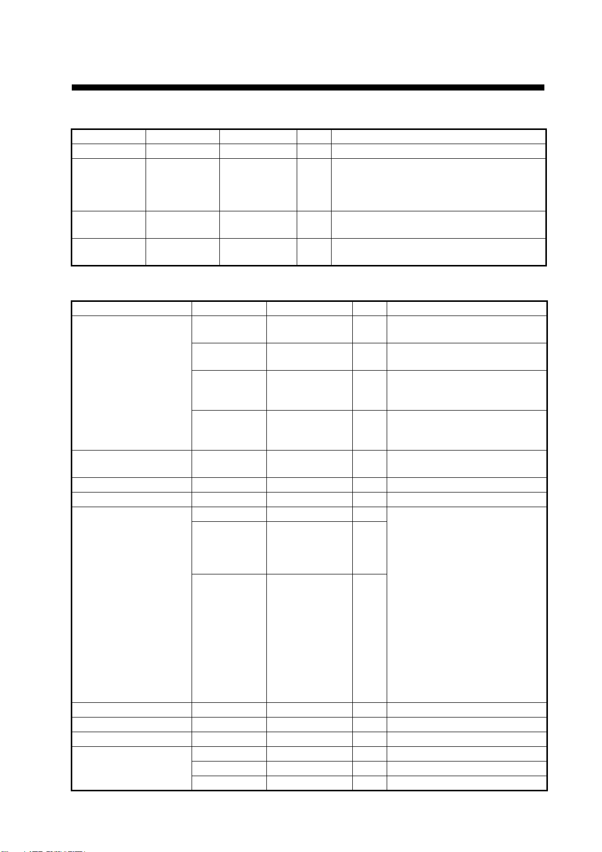
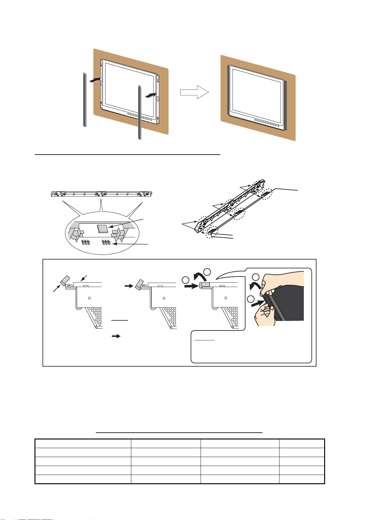
1.2 Flush Mount, Fixed at Front
Flush mount, fix at front is the standard installation method.
1. Use the flush mounting template (supplied) to make a cutout in the mounting location.
2. Attach the flush mounting
sponges H19 and V19 to the
back of the monitor unit in the
order shown in the figure at
right.
3. Attach the flush mount panels 19 to the monitor unit from the rear with the binding head
screws (M4x10, 6 pcs., supplied).
Flush Mounting
Sponge H19 (5 mm)
for top and bottom
Flush Mounting
Sponge V19 (2 mm)
for left and right
Binding Head Screw
Flush Mount Panel 19
Note: Attach the flush mount panels to both sides of the monitor unit with no gap.
4. Connect all cables at the back of the monitor unit. See section 1.8.
5. Set the monitor unit assembly to the cutout.
6. Fix the monitor unit to the cutout with the self-tapping screws (5x20, 4 pcs., supplied).
Self-Tapping Screw
(4 places)
2
Page 12
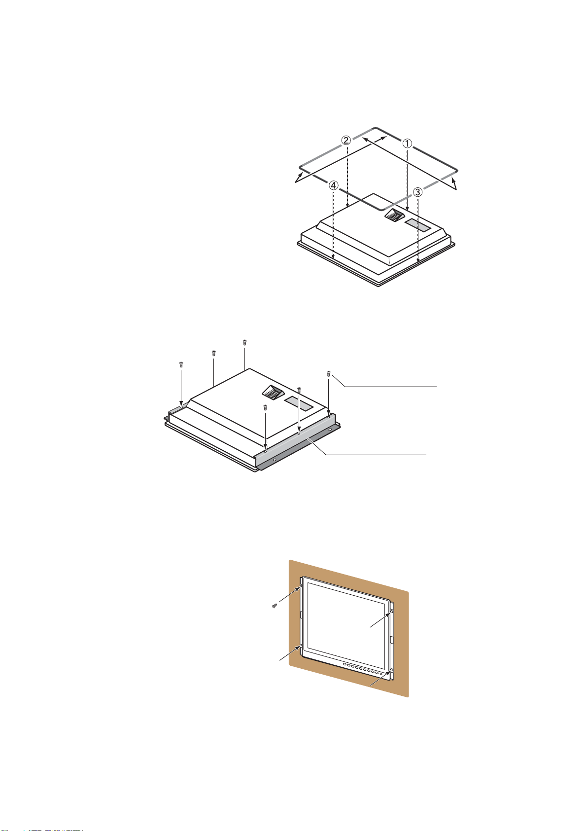
1. MOUNTING, WIRING
7. Set the masking panel to each side of the monitor unit.
Masking Panel for 19” LCD
How to attach or detach the masking panel for 19” LCD
Do the following to attach or detach the masking panel for 19” LCD.
Reverse view of masking panel for 19” LCD
b
Tab A
Tab B
To attach, follow order of right arrow (→). To detach, follow order of left arrow (←).
Monitor unit
Masking
panel
Set tab B to
the edge of
the monitor
unit.
→→
←
Attach: Push the
masking panel for 19”
LCD in the direction
, rotate the panel
toward the monitor
unit, then set each tab
A one by one (three
places of a, b and c) .
c
Set the masking panel for 19” LCD to each side
of the monitor unit. Attach each tab A to the
monitor unit. Be careful not to break the tabs.
2
1
←
Detach: Push the masking panel for 19”
LCD in the direction 1, then release each
tab A one by one
in the direction 2.
a
Front side of
monitor unit
2
1
(three places of a, b and c)
1.3 Flush Mount, Fixed at Front, with Hood
The flush mount, fixed at front method allows you to attach a hood (19) assembly OP26-24 (option) to the monitor unit.
Hood (19) assembly OP26-24 (Code No.: 001-139-370)
Name Type Code No. Qty
Hood (19) Assembly OP26-6-1 001-080-970 1
Knob M4 03-163-2303 100-343-602-10 4
Hood Fixing Plate (19) 26-007-1128 100-366-350-10 2
Binding Head Screw M3x8 000-172-166-10 6
3
Page 13
1. MOUNTING, WIRING
1. Use the flush mounting template (supplied) to make a cutout in the mounting location.
2. Follow steps 2 to 6 in section 1.2.
3. Loosely fix the knobs (4 pcs.) to the hood fixing plates (19) from inside the plates.
Knob
Hood Fixing Plate (19)
4. Remove the binding head screws (M3x5, 6pcs.) and the side panel bases (6 pcs.) from the
flush mount panels 19 attached to the monitor unit.
Side Panel Base (6 pcs.)
Binding Head Screw (6 pcs.)
Flush Mount Panel 19
5. Attach the hood fixing plates (19) and the side panel bases to the right and left sides of the
monitor unit with the binding head screws (M3x8, 6pcs.)
Side Panel Base (6 pcs.)
Binding Head Screw (6 pcs.)
Hood Fixing Plate (19)
6. Press and rub folds on the hood with your hands to make creases clearly. The degree of
creases should be within 90° when the hood is opened.
Hood
Correct
Press and move your hands to
upward and downward several times.
4
Improper
insufficient
Page 14

1. MOUNTING, WIRING
7. Set the cutouts of the hood (19) assembly to the knobs on the hood fixing plates (19).
Knob (4 pcs.)
Hood (19) Assembly
Hood Fixing Plate 19
Cutout (4 places)
8. Press the top of the hood (19) assembly to set the knobs in the cutouts.
Press
Press
9. Set the hood (19) assembly with the knobs tightly (4 pcs.).
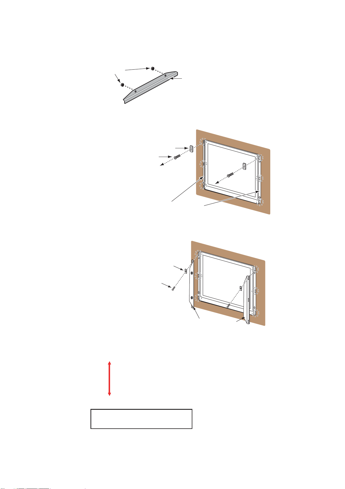
1.4 Flush Mount, Fixed at Rear
The flush mount, fixed at rear method requires the flush mount kit OP26-12 (option, see page vii).
1. Use the flush mounting template (supplied) to make a cutout in the mounting location.
2. Attach the flush mounting sponges
H 19 and V 19 to the back of the
monitor unit in the order shown in
the figure at right.
Flush Mounting
Sponge H 19 for
top and bottom
5
Flush Mounting
Sponge V 19 for
left and right
Page 15

1. MOUNTING, WIRING
3. Screw the wing bolts and the wing nuts of the flush mount fixture 19 so that the protector for
screw moves to the fixing plate.
Wing Bolt
Wing Nut
Fixing Plate
Protector for
Screw
Flush Mount Fixture 19
Move to the fixing plate.
4. Connect all cables at the back of the monitor unit. See section 1.8.
5. Set the monitor unit to the cutout.
6. Fasten the flush mount fixture 19 to the right and left sides of the rear of the monitor unit with
the washer head screws B (6 pcs.).
Washer Head Screw B
(6 places)
Flush Mount Fixture 19
7. Fasten each wing bolt in the order shown in the figure below so that the protector for screw
touches the mounting panel.
8. Fasten the wing bolts tightly to secure the monitor unit.
9. Fasten the wing nuts tightly.
Wing Bolt
Wing Nut
Fixing Plate
Protector for Screw
Mounting
Panel
6
Page 16

1. MOUNTING, WIRING
1.5 Flush Mount, Fixed at Rear, with Hood
The flush mount, fixed at rear method allows you to attach a hood assembly OP26-6 (option) to
the monitor unit.
Hood assembly OP26-6 (Code No.: 001-080-930)
Name Type Code No. Qty
Hood (19) Assembly OP26-6-1 001-080-970 1
Flush Mounting Sponge V 19 26-005-3124 100-351-560-10 2
Hood Fixing Plate 19 26-005-3302 100-351-611-10 2
F-Mount Hood Packing 19 26-005-3305 100-351-620-10 2
Knob M4 03-163-2303 100-343-602-10 4
Flat Head Screw M3x8 000-172-167-10 6
Flush Mounting Template C42-00910 000-172-637-10 1
1. Use the flush mounting template (supplied) to make a cutout in the mounting location.
2. Fix the hood fixing plates 19 to the right and left sides of the monitor unit with the flat head
screws (6 pcs.).
Hood Fixing Plate 19
Flat Head Screw
3. Attach the F-mount hood packing 19 to the top and bottom brims. Then, attach the flush
mounting sponge V 19 to the right and left brims of the monitor unit from the rear side.
F-Mount Hood
Packing 19 for
top and bottom
Flush Mounting
Sponge V 19 for
left and right
4. Follow steps 3 to 9 in section 1.4 to fix the monitor unit to the mounting location.
5. Loosely fix the knobs (4 pcs.) to the hood fixing plate 19 from inside the plate.
7
Page 17

1. MOUNTING, WIRING
6. Set the cutouts of the hood (19) assembly to the knobs on the hood fixing plates 19.
Knob (4 pcs.)
Hood (19) Assembly
Hood Fixing Plate 19
Cutout (4 places)
7. Press the top of the hood assembly to set the knobs in the cutouts.
Press
Press
8. Set the hood assembly with the knobs tightly (4 pcs.).
1.6 Tabletop Mount
You can fix the monitor unit to a tabletop, using the bracket assembly OP26-5 (option).
Bracket Assembly OP26-5 (Code No.: 000-016-270)
Name Type Code No. Qty
Mounting Bracket (19) OP26-5-1 001-080-910 1
Bracket Support w/Knobs OP26-5-2 001-080-920 1
Self-Tapping Screw 5x20 000-162-608-10 4
Binding Head Screw M4x10 000-172-165-10 9
1. Loosen the knobs of the bracket support to separate the mounting bracket (19) from the bracket support.
Mounting Bracket (19)
Bracket Support w/Knobs
Knob
8
Page 18

1. MOUNTING, WIRING
2. Set the mounting bracket to the mounting location with four self-tapping screws.
Self-Tapping Screw
(4 places)
Mounting Bracket (19)
3. Attach the bracket support to the rear of the monitor unit with the binding head screws (9 pcs.).
Bracket Support w/Knobs
Binding Head Screw (9 places)
Binding Head
Screw
Rear view
4. Connect all cables at the back of the monitor unit. See section 1.8.
5. Loosen the knobs of the bracket support and set knobs in the notches on the mounting bracket.
Mounting Bracket (19)
Knob
6. Adjust the angle of the monitor unit and fix the knobs tightly.
How to attach the hood
You can attach a hood to the tabletop-mounted monitor unit, using the hood assembly OP26-6
(option).
1. Follow steps 1 to 3 in section 1.6.
2. Fix the hood fixing plates 19 to the right and left of the monitor unit with the flat head screws
(6 places). (See step 2 in section 1.5.)
3. Follow steps 4 to 5 in section 1.6.
4. Follow steps 5 to 8 in section 1.5.
9
Page 19

1. MOUNTING, WIRING
1.7 Flush Mount a Series Side by Side
You can flush mount two or three monitor units side by side, using the optional flush mount kit
OP26-13 for two monitor units or OP26-14 for three monitor units (see page vii).
1. Make a cutout in the mounting location as shown below (see page D-4).
±1
389
892±1
4-Ø18
(9)
(9)
For two monitor units
±1
389
4-Ø18
(9)
(9)
For three monitor units
1342±1
2. Follow steps 2 to 5 in section 1.4 to set the two or three monitor units in the mounting location.
3. Attach the flush mount fixtures 19 with the washer head screws B to join the two or three monitor units.
Join the two monitor units with the
flush mount fixtures 19 (4 pcs.).
Join the three monitor units with the
flush mount fixtures 19 (6 pcs.).
4. Fasten two or three monitor units tightly. See steps 7 to 9 in section 1.4.
10
Page 20

1. MOUNTING, WIRING
FSV-84/84L
FSV-30/S-BB
FSV-24/S-BB
FCV-30
FCV-1200L/M
FAR-21x7
FEA-2107
FCR-21x7
FEA-2107
FCR-21x7
RGB signal
3COX-2P-6C
5 m/10 m (option)
Digital signal
DVI-D/D S-LINK
5 m (standard)/
10 m (option)
Composite
signal cable
CCD camera
DVD recorder
BRILL CTRL
port *
3
BRILL CTRL
port *
3
*
1
IV-8 sq
(local supply) *
1
DPYC-1.5
(or equivalent)
Slide
switch *
2
Slide
switch *
2
RS-232C cable
(Max. 10 m)
1.8 Wiring
Refer to the figure below and the interconnection diagram at the back of this manual to connect
cables.
Connector
Attach the Terminal Board Gear Cover
again after connecting cables.
Power
switch
Fuse
DPYC-1.5
Armor
Sheath
Conductor
S = 1.5 mm
2
φ = 1.56 mm
φ = 11.7 mm
100-230 VAC
The bottom of the rear of the monitor unit
Slide
IV-8 sq
IV-8 sq
(local supply)
(local supply) *
switch *
1
To ground
terminal on hull
RGB signal
RGB signal
3COX-2P-6C
3COX-2P-6C
5 m/10 m (option)
5 m/10 m (option)
DPYC-1.5
DPYC-1.5
(or equivalent)
(or equivalent)
FSV-84/84L
FSV-30/S-BB
FSV-24/S-BB
FCV-30
FCV-1200L/M
Composite
2
Digital signal
Digital signal
DVI-D/D S-LINK
DVI-D/D S-LINK
5 m (standard)/
5 m (standard)/
10 m (option)
10 m (option)
Composite
signal cable
signal cable
CCD camera
CCD camera
DVD recorder
DVD recorder
FAR-21x7
FEA-2107
FCR-21x7
BRILL CTRL
3
port *
RS-232C cable
RS-232C cable
(Max. 10 m)
(Max. 10 m)
FEA-2107
FCR-21x7
*1: Attach a crimp-on lug (inner dia. φ4) for monitor unit side. Make the length of the ground wire
as short as possible.
*2: Slide switch
• ON (upward): Allow digital signal from external equipment to control on/off of the monitor unit.
• OFF (downward): Set to OFF for analog RGB signal.
Note: Turn the slide switch off when you connect equipment to both the DVI and RGB ports.
*3: BRILL CTRL port
No use. Do not remove the sticker from the connector.
How to fix power cable
Fix the power cable with the cable clamp to prevent it from loosening.
MU-190
Cable
clamp
Replace MU-201CE with MU-190
Cut the connector of the power
cable (15-565, supplied on the
MU-201CE). Attach a crimp-on lug
(supplied on the MU-190) to each
cable core then connect the
cables as in the figure at right.
Length: 40 mm
Length: 60 mm
Local supply
11
Page 21

2. ADJUSTMENTS
Slide switch ON (Default setting)
䋨Ꮏ႐⩄ᤨ䈱⁁ᘒ䋩
Adjust the MU-190 according to the equipment connected.
Note: Sections 2.2, 2.3 and 2.4 are for Non-SOLAS.
2.1 Installation Settings
The [INSTALLATION SETTING] menu appears only when the power is turned on for the first time
after installation.
INSTALLATION SETTING
EXT BRILL CTRL
SERIAL BAUDRATE
COLOR CALIBRATION
KEY LOCK
SAVE AND EXIT
RS-232C
9600bps
ON
ON
YES
(OFF/DVI1/DVI2/RS-232C/RS-485/USB)
(4800/9600/19200/38400)
(OFF/ON)
(OFF/ON)
(NO/YES)
Menu
Menu item
For ECDIS (FEA-2107) or chart radar (FCR-21x7), no adjustment is necessary. Keep this equipment in the default settings.
For IMO radar (FAR-21x7) or Non-SOLAS, adjust this equipment according to the equipment connected, referring to the following table.
Connected
equipment
FEA-2107, FCR-21x7 RS-232C 9600 ON ON ON
FAR-21x7 DVI *1 - OFF ON ON
Other OFF - OFF OFF OFF
EXT BRILL
CTRL
SERIAL
BAUDRATE
COLOR
CALIBRATION
KEY
LOCK
DVI PWR
SYNC *2
Gray items: Default setting
*1: To connect to the processor unit of a radar, connect the video signal cable to the DVI-D1 port.
Then, select DVI1 to display the radar picture (see section 3.4).
*2: "DVI PWR SYNC" is the slide switch at the bottom rear of the monitor unit. See the “Slide
switch” below.
Slide switch
Set the slide switch (located between RGB and DVI ports) to OFF when you connect the RGB
signal or both RGB and DVI signals. Otherwise, the monitor will not turn on. The slide switch is set
at the factory to ON to control the power on/off from the equipment connected via DVI signal.
Slide switch
RGB port
Bottom rear of the monitor unit
ON (Default setting)
DVI port
OFF
12
Page 22

2. ADJUSTMENTS
1. Press the S or T key to select the menu item to adjust on the [INSTALLATION SETTING]
menu. The menu item and setting currently selected (the cursor) is shown in orange.
2. Press the W or X key to change the setting.
3. After you adjust all settings, press the T key to select [SAVE AND EXIT]. The confirmation
message appears.
INSTALLATION SETTING
EXT BRILL CTRL
SERIAL BAUDRATE
COLOR CALIBRATION
KEY LOCK
SAVE AND EXIT
Save configuration changes and exit now? YES[
RS-232C
9600bps
ON
ON
YES
(OFF/DVI1/DVI2/RS-232C/RS-485/USB)
(4800/9600/19200/38400)
(OFF/ON)
(OFF/ON)
(NO/YES)
]
NO[]
4. Press the X key. The settings are saved and the menu is closed.
Note: To cancel the settings, press the W key. The indication changes from [YES] to [NO] and
you can move the cursor to the menu items with the S key.
[INSTALLATION SETTING] menu descriptions
Menu item Function Setting
[EXT BRILL CTRL] Adjust the brilliance of the monitor unit from the external
equipment.
[OFF]: You can not adjust the brilliance from the external
[OFF], [DVI1],
[DVI2], [RS-232C],
[RS-485], [USB]
equipment. You can adjust the brilliance with the /
BRILL key.
[DVI1]: When the DVI1 signal is shown, you can adjust
the brilliance of this display from the equipment connected to DVI-D1 port. For the screen other than the DVI1,
you can adjust the brilliance with the /BRILL key.
[DVI2]: When the DVI2 signal is shown, you can adjust
the brilliance of this display from the equipment connected to DVI-D2 port. For the screen other than the DVI2,
you can adjust the brilliance with the /BRILL key.
[RS-232C]:You can adjust the brilliance from the equipment connected to RS-232C port.
[RS-485], [USB]: No use.
[SERIAL
BAUDRATE]
Select the serial baud rate according to the equipment
connected.
Note: This function is available when you set [EXT
BRILL CTRL] to [RS-232C].
[4800bps],
[9600bps],
[19200bps],
[38400bps]
[COLOR
CALIBRATION]
Select whether to use color-adjusted correction data or
not.
[OFF]: Do not use the adjusted data.
[ON]: Use the adjusted data.
[KEY LOCK] Select whether to lock the key operation or not (see
paragraph 3.2.2).
[OFF]: Do not lock the key operation.
[ON]: Lock the key operation.
[SAVE AND EXIT] Select whether to save the settings or not.
[NO]: Cancel the settings.
[YES]: Save the settings.
13
[OFF], [ON]
[OFF], [ON]
[NO], [YES]
Page 23

2. ADJUSTMENTS
How to open the [INSTALLATION SETTING] menu
Turn off the monitor unit. While you hold the DISP key, press the /BRILL key to turn on the monitor unit. Press and hold the DISP key for more than five seconds.
Note: When the "DVI PWR SYNC" slide switch is ON, turn on the connected external equipment
while you press the DISP key to turn on the monitor unit.
2.2 RGB/DVI Setting (For Non-SOLAS)
You can adjust the screen from the RGB, DVI-D1 and DVI-D2 ports individually. Turn on each external equipment and adjust the monitor unit as follows.
1. Select the signal to adjust at the DISP selection window. See section 3.4.
1) Press the DISP key.
2) Press the S or T key to select [RGB], [DVI1] or [DVI2].
2. Press the MENU key to show the menu. The main menu closes automatically when there is
no operation for one minute.
3. Press the W or X key to select [RGB], [DVI1] or [DVI2]. The current setting (the cursor) is
shown in orange. The menu items available depend on the selected menu. The [DVI1] and
[DVI2] setting menus contain the same items.
Note: The menus in gray are not available because of no signal.
RGB DVI1 DVI2 VIDEO OSD SYSTEM
H_SIZE
V_SIZE
PHASE
BRIGHTNESS
CONTRAST
H_POSITION
V_POSITION
R_LEVEL
G
_LEVEL
B_LEVEL
TEMPERATURE
B STRETCH
W
STRETCH
DISP MODE
SHARPNESS
1280
1024
(1~32)
16
(1~256)
128
(1~64)
32
(1~99)
50
(1~40)
20
(1~256)
128
(1~256)
128
(1~256)
128
(5000K~9300K)
7000K
(OFF, 1~10)
OFF
(OFF, 1~10)
OFF
(FULL/NORMAL)
FULL
(1~10)
5
Menu
Menu
item
RGB DVI1 DVI2 VIDEO OSD SYSTEM
(1~256)
BRIGHTNESS
CONTRAST
H_POSITION
V_POSITION
R_LEVEL
G
_LEVEL
B_LEVEL
TEMPERATURE
B STRETCH
W
STRETCH
DISP MODE
SHARPNESS
128
(1~64)
32
(1~50)
25
(1~40)
20
(1~256)
128
(1~256)
128
(1~256)
128
(5000K~9300K)
7000K
(OFF, 1~10)
OFF
(OFF, 1~10)
OFF
(FULL/NORMAL)
FULL
(1~10)
1
DVI setting menu
RGB setting menu
4. Press the S or T key to select the menu item to adjust.
5. Press the W or X key to adjust the setting.
6. Press the MENU key to close the menu.
14
Page 24

2. ADJUSTMENTS
[RGB], [DVI1/2] menu descriptions
Menu item Function Setting
H_SIZE (Only for
RGB menu)
V_SIZE (Only for
RGB menu)
PHASE** (Only
for RGB menu)
BRIGHTNESS Adjust the red, green and blue color level at one time. 1 to 256
CONTRAST Adjust the contrast level.
H_POSITION Move the image position horizontally.
V_POSITION Move the image position vertically.
R_LEVEL Adjust the red color level.
G_LEVEL Adjust the green color level.
B_LEVEL Adjust the blue color level.
TEMPERATURE Adjust the color temperature.
B STRETCH Emphasize the black color.
W STRETCH Emphasize the white color.
DISP MODE* Select the display method.
SHARPNESS** Sharpen the edges horizontally.
Adjust the image size horizontally.
Horizontal size: W (narrow), X (wide)
Adjust the image size vertically.
Vertical size: W (narrow), X (wide)
Adjust the sample timing so that the flicker disappears and
the text is clear.
W (darken), X (brighten)
W (leftward), X (rightward)
W (upward), X (downward)
W (weaken), X (strengthen)
W (weaken), X (strengthen)
W (weaken), X (strengthen)
W (strengthen the red color level),
X (strengthen the blue color level)
[OFF] (standard), W (weaken), X (strengthen)
[OFF] (standard), W (weaken), X (strengthen)
[FULL]: Show the input signal on entire screen.
[NORMAL]: Show the input signal with original aspect ratio.
W (soften characters and lines),
X (sharpen characters and lines)
Depending on input signal
1 to 32
1 to 64
1 to 99 (RGB),
1 to 50 (DVI1,
DVI2)
1 to 40
1 to 256
1 to 256
1 to 256
5000 to 9300K
(Step is 100.)
[OFF], 1 to 10
[OFF], 1 to 10
[FULL],
[NORMAL]
1 to 10
*: When inputting VGA, SVGA or XGA, a circle may be displayed as an ellipse because the aspect
ratio differs. In this case, set [DISP MODE] to [NORMAL] on the [RGB], [DVI1], or [DVI2] menus.
A black bar appears on the top and bottom of the picture, but this is normal.
**: If the characters are not clear, adjust [PHASE] and [SHARPNESS].
15
Page 25

2. ADJUSTMENTS
2.3 Video Composite Signal Setting (For Non-SOLAS)
You can adjust the VIDEO signal from the VIDEO port. The VIDEO signal is also displayed in the
PIP window (see section 3.5).
1. Select the signal to adjust at the DISP selection window.
2. Press the MENU key to show the menu.
3. Press the W or X key to select [VIDEO].
RGB DVI1 DVI2 VIDEO OSD SYSTEM
PIP_SIZE
CONTRAST
R_LEVEL
G
_LEVEL
B_LEVEL
TEMPERATURE
B STRETCH
W
STRETCH
5
(1~10)
32
(1~64)
128
(1~256)
128
(1~256)
128
(1~256)
7000K
(5000K~9300K)
OFF
(OFF, 1~10)
OFF
(OFF, 1~10)
4. Press the S or T key to select the menu item to adjust.
5. Press the W or X key to adjust the setting.
6. Press the MENU key to close the menu.
[VIDEO] menu descriptions
Menu item Function Setting
PIP_SIZE Adjust the size of the picture-in-picture window.
Note: This setting is available when the PIP window is displayed.
CONTRAST Adjust the contrast level.
1 (52 mm x 35
mm) to 10 (285
mm x 194 mm)
1 to 64
W (darken), X (brighten)
R_LEVEL Adjust the red color level.
1 to 256
W (weaken), X (strengthen)
G_LEVEL Adjust the green color level.
1 to 256
W (weaken), X (strengthen)
B_LEVEL Adjust the blue color level.
1 to 256
W (weaken), X (strengthen)
TEMPERATURE Adjust the color temperature.
W (strengthen the red color level),
5000 to 9300K
(Step is 100.)
X (strengthen the blue color level)
B STRETCH Emphasize the black color.
[OFF], 1 to 10
[OFF] (standard), W (weaken), X (strengthen)
W STRETCH Emphasize the white color.
[OFF], 1 to 10
[OFF] (standard), W (weaken), X (strengthen)
16
Page 26

2. ADJUSTMENTS
2.4 The Menu Window Setting (For Non-SOLAS)
2.4.1 How to adjust the menu window
You can adjust the position and transparency of the menu window on the [OSD] (On Screen Display) menu.
1. Press the MENU key to show the menu.
2. Press the W or X key to select [OSD].
RGB DVI1 DVI2 VIDEO OSD SYSTEM
H_POSITION
V_POSITION
TRANSLUCENT
CUSTOM NAME
RGB : RGB
DVI1 : DVI1
DVI2 : DVI2
VIDEO : VIDEO
14
33
OFF
(1~29)
(1~37)
(OFF/ON)
3. Press the S or T key to select the menu item to adjust.
4. Press the W or X key to adjust the setting.
5. Press the MENU key to close the menu.
[OSD] menu descriptions
Menu item Function Setting
H_POSITION Move the menu window horizontally.
W (leftward), X (rightward)
V_POSITION Move the menu window vertically.
W (upward), X (downward)
TRANSLUCENT Adjust the transparency of the background color (blue) on
the menu window.
[OFF]: Blue, [ON]: Translucent
Note: Alpha blending technology is used for transparency
effects.
1 to 29
1 to 37
[OFF], [ON]
CUSTOM NAME See paragraph 2.4.2.
17
Page 27

2. ADJUSTMENTS
2.4.2 How to change the signal name
You can change the signal name ([RGB], [DVI1/2] or [VIDEO]) to a name (ex. the equipment
name) which is easy to understand. The name is shown in the DISP selection window and the
indication shown at the upper right of the screen (see section 3.4).
1. Press the MENU key to show the menu.
2. Press the W or X key to select [OSD].
3. Press the S or T key to select the signal to change its name in the signal name area. In the
example below, [RGB] is selected.
RGB DVI1 DVI2 VIDEO OSD SYSTEM
Signal
name area
H_POSITION
V_POSITION
TRANSLUCENT
CUSTOM NAME
RGB : RGB
DVI1 : DVI1
DVI2 : DVI2
VIDEO : VIDEO
14
33
OFF
(1~29)
(1~37)
(OFF/ON)
4. Press the X key to select the character to change. In the example below, "G" of RGB is se-
lected.
CUSTOM NAME
RGB : RGB
DVI1 : DVI1
DVI2 : DVI2
VIDEO : VIDEO
5. Press the S or T key to select an appropriate alphanumeric character. In the example below,
"5" is selected. You can use a maximum of ten characters. “A to Z”, “0 to 9”, “–”, “.”, “ ” (space)
are available.
CUSTOM NAME
RGB : R5B
DVI1 : DVI1
DVI2 : DVI2
VIDEO : VIDEO
6. To change another signal name, press the W key several times to return the cursor to the sig-
nal name area. Repeat steps 3 to 5.
7. Press the MENU key to close the menu.
18
Page 28

3. OPERATION
Note: When you connect the monitor unit to FAR-21x7, FEA-2107 or FCR-21x7, you can turn the
power on/off and adjust the brilliance via the application of the FAR-21x7, FEA-2107 or FCR-21x7
only (see section 2.1).
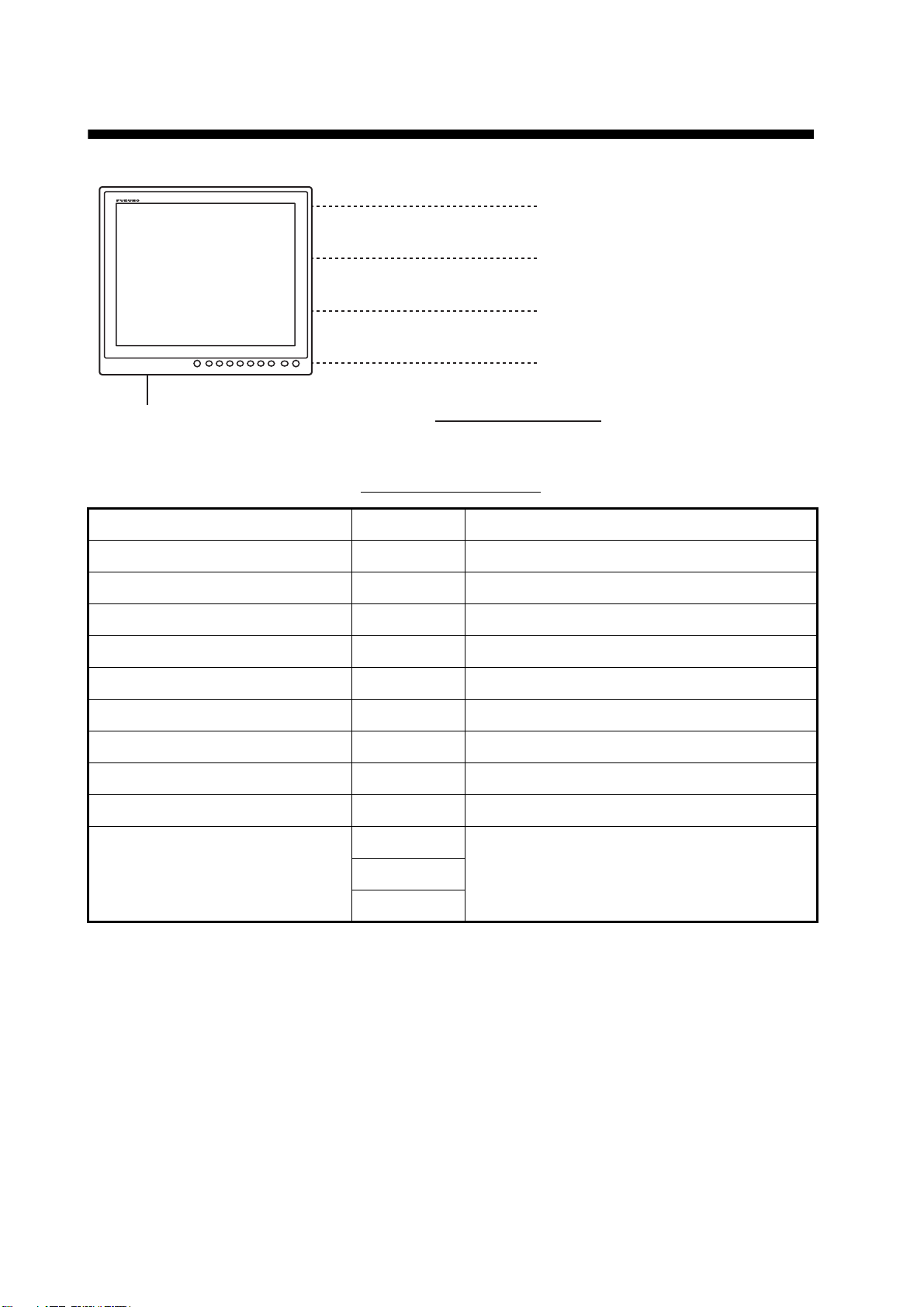
3.1 Controls
MENU DISP
PIP
L
B
L
I
R
- Power On/Off. (Available
when the slide switch at the
bottom rear is OFF.)
- Display the brilliance
Open/Close the menu.
MENU DISP
Light sensor
(Automatically
detect the ambient
brightness.)
- Select the menu and
menu items.
- Adjust the setting.
- Move the PIP window.
Select the signal to display.
PIP
Display/Hide
the PIP window.
adjustment window.
B
L
R
L
I
Power LED
(Lights when power is on.)
Green: The signal is input.
Orange: No signal.
The dimmer for the power LED and keys changes with the display brilliance. Also, when you connect the monitor unit to FAR-21x7, FEA-2107 or FCR-21x7, the dimmer for the power LED and
keys changes with the brilliance modes (Day, Dusk, Night) of those models. When you connect
the monitor unit to the equipment other than FAR-21x7, FEA-2107 or FCR-21x7, the control is
done from the MU-190. If the keys of MU-190 are not illuminated, provide external, dimmable illumination, e.g. gooseneck lamp.
3.2 How to Turn the Power On/Off
3.2.1 Turn the power on/off
How to turn on/off the power depends on the setting of the slide switch. The slide switch is set
when the monitor unit is installed. See section 1.8.
Note: The screen refreshes slower in low ambient temperature.
19
Page 29

3. OPERATION
Slide switch “ON”
The external equipment connected to the DVI port (DVI-D1 or DVI-D2) can turn on/off the monitor
unit. See the operator’s manual for the external equipment connected.
Note 1: You can not turn on the power with the /BRILL key on MU-190.
Note 2: When you connect the cables to both DVI-D1 and DVI-D2 ports, turn off the power of both
equipment to turn off the monitor unit.
Slide switch “OFF”
1. Press the /BRILL key to turn on the monitor unit.
2. Press and hold the /BRILL key for three seconds to
turn off the monitor unit. While you hold the key, the
message shown right appears on the screen.
This monitor will shut down in three seconds.
SHUT DOWN
3.2.2 Unlock the key operation
All the keys of the monitor unit are locked by default. Unlock the keys to operate all menus.
1. Turn off the monitor unit.
2. While you hold the PIP key, press the /BRILL key to turn on the monitor unit. Press and hold
the PIP key for more than five seconds. The key operation is unlocked.
Note: When the slide switch is ON, turn on the connected external equipment while you press
the PIP key to turn on the monitor unit.
3. To lock the key operation, turn off the monitor unit and then turn it on while you hold the PIP
key.
The setting of [KEY LOCK] in the [INSTALLATION SETTING] menu ([OFF/ON]) is mutually
changed.
3.3 How to Adjust the Display Brilliance
You can adjust the display brilliance as follows:
Note: This function is available when [AUTO DIMMER] on the [SYSTEM] menu is [OFF] and [EXT
BRILL CTRL] on the [INSTALLATION SETTING] menu is [OFF]. See section 2.1 and
paragraph 3.6.1.
1. Press the /BRILL key momentarily to show the BRILL
adjustment window. The window shown right disappears if there is no operation for five seconds.
2. Press the W or X key to adjust the brilliance (setting range: 1 - 50).
3. Press the S or T key to close the window.
Warning: If you turn off the monitor unit with minimum brilliance, the unit starts with minimum brilliance the next time it is turned on. This can make it difficult to see warnings from applications connected, etc. depending on current lighting conditions. If this occurs, do the following according to
the equipment connected;
For FAR-21x7, FEA-2107, FCR-21x7: The brilliance of the monitor unit is adjusted only via the
application of those equipment. See the appropriate operator’s manual.
For Non-SOLAS: Press the /BRILL key repeatedly to adjust the brilliance.
BRILL 46
20
Page 30

3. OPERATION
3.4 How to Select the Source for Main Picture
Select the signal to display on the entire screen as follows:
1. Press the DISP key to show the DISP selection window. The window shows
the signal names as you customized them at paragraph 2.4.2. This window
disappears if there is no operation for five seconds.
2. Press the S or T key to select a signal.
[RGB]: Show the signal from the RGB port.
[DVI1], [DVI2]: Show the signal from the selected DVI port.
[VIDEO]: Show the external video from the VIDEO port.
3. Press the W or X key to close the window. The name of the selected signal appears at the
right top corner for five seconds after the DISP selection window disappears. If there is no signal, "NO SIGNAL" appears.
RGB
DVI1
DVI2
VIDEO
3.5 How to Display the PIP Window
The PIP (picture-in-picture) window, which displays the picture input to the VIDEO port, is available on the RGB, DVI1 and DVI2 displays.
PIP window
1. With the RGB, DVI1 or DVI2 display shown, press the PIP key to show the PIP window. To
hide the PIP window, press the PIP key again.
2. You can move the PIP window by pressing the arrow keys when the menu is closed.
Note: You can adjust the size of the PIP window on the [VIDEO] menu (see section 2.3).
3.6 SYSTEM Menu
The [SYSTEM] menu controls the brilliance, clears the memory and shows signal status and program number.
3.6.1 How to set the auto dimmer
The auto dimmer feature automatically adjusts the brilliance according to the ambient brightness
detected by the light sensor on the front panel. Also, you can select the interval at which the brilliance is adjusted.
Note: Do not put any objects in front of the light sensor.
1. Press the MENU key to show the menu.
21
Page 31

2. Press the X key to select [SYSTEM].
RGB DVI1 DVI2 VIDEO OSD SYSTEM
3. OPERATION
AUTO DIMMER
DEFAULT RESET
INFORMATION
RGB :
DVI1 :
DVI2 :
VIDEO
SERIAL No.
APR PROGRAM No.
FPGA PROGRAM No.
ELAPSED TIME
OFFNO(OFF, 1~5)
(NO/YES)
1280*1024 Fh : 80.0kHz Fv : 75Hz
1280*1024 Fh : 64.0kHz Fv : 60Hz
NO SIGNAL
: NTSC
: 8073-5578, 987655
: 2651020-01.XX
: 2651021-01.XX
: 100000
Signal status,
serial number,
program number
and elapsed time
3. Press the S or T key to select [AUTO DIMMER].
4. Press the W or X key to select an interval to check brightness.
• [OFF]: Turn of this function. • [3]: Every minute
• [1]: Every two seconds • [4]: Every three minutes
• [2]: Every 30 seconds • [5]: Every five minutes
Note: When you connect the monitor unit to FAR-21x7, FEA-2107 or FCR-21x7, set to [OFF].
5. Press the MENU key to close the menu.
3.6.2 How to clear the memory
You can clear the memory to restore the default settings.
1. Press the MENU key to show the menu.
2. Press the X key to select [SYSTEM].
3. Press the S or T key to select [DEFAULT RESET].
4. Press the X key. The indication changes from "NO" to "YES".
RGB DVI1 DVI2 VIDEO OSD SYSTEM
AUTO DIMMER
DEFAULT RESET
ALL CUSTOM SETTINGS WILL BE LOST.
← KEY: CANCEL → KEY: RESET
INFORMATION
RGB :
DVI1 :
DVI2 :
VIDEO
SERIAL No.
APR PROGRAM No.
FPGA PROGRAM No.
ELAPSED TIME
OFF
(OFF, 1~5)
YES
(NO/YES)
1280*1024 Fh : 80.0kHz Fv : 75Hz
1280*1024 Fh : 64.0kHz Fv : 60Hz
NO SIGNAL
: NTSC
: 8073-5578, 987655
: 2651020-01.XX
: 2651021-01.XX
: 100000
Note: To cancel, press the W key. The indication changes from "YES" to "NO".
5. Press the X key to select [RESET].
22
Page 32

4. MAINTENANCE,
WARNING
TROUBLESHOOTING
NOTICE
Do not apply paint, anti-corrosive sealant or contact spray
to coating or plastic parts of the equipment.
Those items contain organic solvents that can damage coating
and plastic parts, especially plastic connectors.
4.1 Maintenance
Routine maintenance
Regular maintenance is important for good performance. Check the following on a regular basis
to keep the equipment in good condition.
• Check that the connectors at the bottom of the monitor unit are tightly fastened.
• Check the ground wire and ground terminal for rust. Clean if necessary. Confirm that the ground
wire is tightly fastened.
• Remove dust and dirt from the monitor unit with a dry, soft cloth. Do not use chemical cleaners to
clean any part of the monitor unit. They can remove paint and markings.
• Wipe the LCD carefully to prevent scratching, using an LCD cleaning cloth (supplied as accessory). To remove dirt or salt deposits, use an LCD cleaner, wiping slowly with tissue paper so as to
dissolve the dirt or salt. Change paper frequently so the salt or dirt will not scratch the LCD. Do
not use solvents such as thinner, acetone or benzene for cleaning. Also, do not use degreaser or
antifog solution, as they can strip the coating from the LCD.
Fuse replacement
The fuse in the fuse holder at the bottom of the display
protects the equipment from overvoltage and overcurrent.
If the fuse blows, find the cause before you replace it. If the
fuse blows again after replacement, request service.
Name Type Code Number Remarks
Glass Tube Fuse FGBO 250V 1A PBF 000-155-828-10
LCD replacement
Use the proper fuse.
Use of a wrong fuse can cause
fire or damage to the equipment.
WARNING
The life of the LCD is approximately 50,000 hours. The actual number of hours depends on ambient temperature and humidity. When the brilliance cannot be raised sufficiently, replace the
LCD.
Fan replacement
The life of the each fan is shown in the table on the next page. The actual number of hours depends on ambient temperature. When the fan does not rotate sufficiently, the message "FAN ERROR" is shown. Turn off the power and call for service to request replacement of the fan.
23
Page 33
4. MAINTENANCE, TROUBLESHOOTING
Item Life Type Code Number
FAN1 Approximately 40,000 hours MFB52A-12HA-001 000-172-023-10
FAN4 Approximately 60,000 hours LQ0DDB0094 000-172-144-10
4.2 Troubleshooting
See the following table to find the possible causes of trouble and the actions to restore normal
operation. If repair of the equipment is necessary, report the result of the troubleshooting to the
service technician.
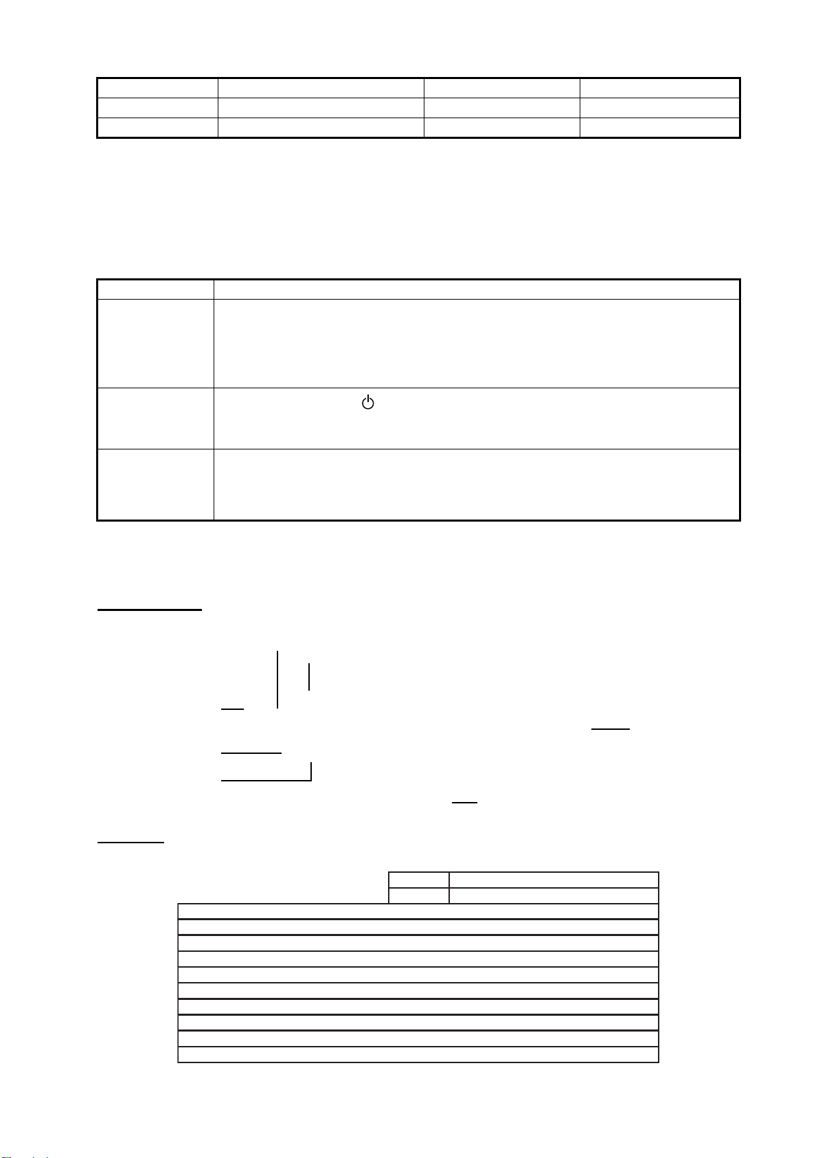
Case Remedy
You can not turn
on the power.
You can not turn
off the power.
No picture • Fasten the cables tightly.
• Check if the power switch at the bottom of the display is on.
• Check the setting of the slide switch.
• Check the battery voltage with a multimeter.
• Check the fuse at the bottom of the display.
• Fasten the power cable tightly.
• Press and hold the /BRILL key for eight seconds.
• When the slide switch is set to ON, turn off the external equipment connected
to turn off the monitor.
• Check the input signal. See section 3.6.
• Check the setting for DISP selection window. See section 3.4.
• Check if the display brilliance is not set to minimum.
4.3 Parts Location and Parts List
Parts location
MFB52A-12HA-001, 26S0028 (Fan (FAN1), Wind direction: top-left)
LQ0DDB0094, 26S0048 (Fan motor assembly (FAN4), Wind direction: upward)
OZP-120-12/15-J06
26P0023
ESSIP33A-1C
(AD board)
Parts list
ELECTRICAL PARTS
PRINTED CIRCUIT BOARD Code No.
OZP-120-12/15-J06
26P0023 (PSW board)
ESSIP33A-1C (AD board)
26P0013
LCD
LQ190E1LX51, 26S0027
FAN
MFB52A-12HA-001, 26S0028 (FAN1)
LQ0DDB0094, 26S0048 (FAN4)
26P0013
Model
Unit
MU-190
Monitor unit MU-190
Code No.
Code No.
LQ190E1LX51,
26S0027 (LCD)
-
-
-
-
-
-
-
24
Page 34

FURUNO
SPECIFICATIONS OF MONITOR UNIT
MU-190
1 GENERAL
1.1 Display 19-inch color LCD
1.2 Effective area 376.32 x 301.06 mm
1.3 Resolution SXGA (1280 x 1024 pixel)
1.4 Pixel pitch 0.294 mm (Horizon/Vertical)
1.5 Brightness 450 cd/m2 typical
1.6 Contrast 900: 1
1.7 View angle 160° (up/down, left/right 80° or more)
1.8 Visible distance 1.02 m nominal
1.9 Input signal
RGB analog 1 port, non-interlace, RGB signal: 0.7 Vp-p, Sync. Signal: TTL level
MU-190
DVI-D 2 ports, DVI-standard, VESA DDC2B
Composite signal 1 port, NTSC/PAL-standard, Video signal: 0.7 Vp-p
USB USB1.1, 12 Mbps (for dimmer control)
RS-232C EIA/TIA-232, 9600 bps (4800/19200/38400 bps)
2 POWER SUPPLY
100-230 VAC: 0.7-0.4 A, 1 phase, 50/60Hz
3 ENVIRONMENTAL CONDITION
3.1 Ambient temperature -15°C to +55°C
3.2 Relative humidity 93% or less at 40°C
3.3 Degree of protection IP22
3.4 Category of equipment Protected from the weather
3.5 Vibration IEC 60945 Ed.4
5 UNIT COLOR
N2.5
SP - 1 E3519S04C
Page 35

工事材料表
,
A-1
INSTALLATION MATERIALS
番 号
NO.
1
2
3
4
5
6
7
8
名 称
NAME
FマウントスポンジV19
FLUSH MOUNTING SPONGE
V 19
化粧パネル19
MASKING PANEL FOR 19"
LCD
FマウントスポンジH19
FLUSH MOUNTING SPONGE
H19
+トラスタッピンネジ 1シュ
SELF-TAPPING SCREW
コンベックス
CONVEX
圧着端子
CRIMP-ON LUG
+バインドコネジ
BINDING HEAD SCREW
Fマウントパネル19組品
FLUSH MOUNT PANEL 19
MU-190
略 図
OUTLINE
CODE NO.
TYPE
型名/規格
DESCRIPTIONS
26-005-3124-0
CODE NO.
26-007-1124-2
CODE NO.
26-007-1127-0
CODE NO.
5X20 SUS304
CODE NO.
CV-125N
CODE NO.
FV1.25-4(LF)
CODE NO.
M4X10 SUS304
CODE NO.
CP26-01603
CODE NO.
001-116-250-00
CP26-01601
100-351-560-10
100-363-462-10
100-363-240-10
000-162-608-10
000-172-164-10
000-166-666-10
000-172-165-10
001-134-900-00
数量
Q'TY
2
2
2
4
1
2
6
2
26AH-X-9401
用途/備考
REMARKS
-2
1/1
型式/コード番号が2段の場合、下段より上段に代わる過渡期品であり、どちらかが入っています。 なお、品質は変わりません。
TWO TYPES AND CODES MAY BE LISTED FOR AN ITEM. THE LOWER PRODUCT MAY BE SHIPPED IN PLACE OF THE UPPER PRODUCT.
QUALITY IS THE SAME.
(略図の寸法は、参考値です。 DIMENSIONS IN DRAWING FOR REFERENCE ONLY.)
FURUNO ELECTRIC CO .
LTD.
26AH-X-9401
Page 36

D-1
Page 37

D-2
Page 38

D-3
Page 39

D-4
Page 40

レーダー制御部
S-1
RADAR PROCESSOR UNIT
DVI-D
DVIOTX2_N
J3
12345
RPU-013(FAR-2117ser.)
NC
DVIOTX2_P
A_GNDNCNC
6NC7
NC
8
NCNCNCNCGND
A_GND
DVIOTX1_N
DVIOTX1_P
9
101112131415161718192021222324
VccNCDVIOTXD_N
DVIOTXD_P
A_GND
A_GND
DVIOTXC_P
DVIOTXC_N
ECDIS演算部
DVI1/2
ECDIS PROCESSOR UNIT
EC-1000C
COM1
輝度制御用
DCD
RXD
123
FOR BRILL. CONTROL
TXDRIDTR
4
GND
DSR
RTS
CTS
56789
TITLE
MU-190/231
表示部
名称
相互結線図
NAME
MONITOR UNIT
INTERCONNECTION DIAGRAM
*2
6NC7
8
9
NC
DDC_DATA
DDC_CLOCK
TMDS_DATA1_N
RGB
RED
J2
1234567NC8
P
101112131415161718192021222324
NCNCNC
TMDS_DATA1_P
TMDS_DATA1_SHIELD
GND
GREEN
BLUE
5V_P
GND
GND
GND
HOT_PLUG_DETECT
GND
P
TMDS_DATA0_N
TMDS_DATA0_P
TMDS_DATA0_SHIELD
GNDNCNC
9
1011121314
NC
NC
TMDS_CLOCK_SHIELD
HSYNC_N
VSYNC_N
P
TMDS_CLOCK_P
TMDS_CLOCK_N
NC
15
3
DVI-D/D SINGLELINK5M/10M
5/10m,φ7
12345
J3
DVI-D1
TMDS_DATA2_N
表示部
MONITOR UNIT
MU-190/231
P
TMDS_DATA2_P
TMDS_DATA2_SHIELD
POWER
TB1
*1
NC
AC
AC
1
2
VIDEO
J5
*1
BNC
*1
*2
DVI-D/D SINGLELINK5M
5m,φ7
24 24
J4DVI-D2
同上
DITTO
VBUSD-D+
BRILL CTRL
J6
123
*3
123
J7 Dsub-9P
NC
RS-232C
GND
4
DSUB9P-DSUB9P-5M
TXD
RXD
4
56789
GND
RD-C
TD-B
REF.No.
kg
T.YAMASAKI
MASS
T.TAKAHASHI
C3524-C01- A
*1
NC
TD-A
RD-H
IV-8sq.
DRAWN
31/Aug/2010
31/Aug/2010
DWG No.
SCALE
APPROVED
CHECKED
DPYC-1.5
100-230VAC
12 4
1φ,50/60Hz
*2
3COX-2P-6C,5/10m,φ8.5
魚群探知機
ソナー
レーダー
プロッタ
A
ECHO SOUNDER
SONAR
RADAR
PLOTTER
COAX. CABLE (75Ω)
VIDEO DEVICE
B
USB CABLE,MAX.5m
EXTERNAL EQUIPMENT
注記
*1)造船所手配。
*2)オプション。
*3)EC-1000C構成組品。
C
NOTE
*1: SHIPYARD SUPPLY.
*2: OPTION.
*3: CABLE ASSY. INCLUDED IN MATERIAL FOR EC-1000C.
Page 41

 Loading...