

Page 1
MULTI-PURPOSE LCD DISPLAY
MU-155C
Page 2
SAFETY INSTRUCTIONS
Safety Instructions for the Operator
WARNING
Do not open the equipment.
Only qualified personnel
should work inside
the equipment.
Do not disassemble or modify the
equipment.
Fire, electrical shock or serious injury can
result.
Use the proper fuse and power cable.
Fuse rating is shown on the equipment.
Use of a wrong fuse can result in damage
to the equipment.
Immediately turn off the power at the
switchboard if the equipment is emitting
smoke or fire.
Safety Instructions for the Installer
WARNING
Do not open the cover
unless totally familiar with
electrical circuits and
service manual.
Improper handling can result
in electrical shock.
Turn off the power at the switchboard
before beginning the installation.
Fire or electrical shock can result if the
power is left on.
Do not install the equipment where it
may get wet from rain or water splash.
Water in the equipment can result in fire,
electrical shock or damage to the equipment.
Continued use of the equipment can cause
fire or electrical shock. Contact a FURUNO
agent for service.
Do not place any object near the exhaust
or intake vent.
Fire may result.
CAUTION
Do not connect/disconnect the signal
cable while turning the power on.
The unit may be damaged.
A warning label is attached to the
equipment. Do not remove the label.
If the label is missing or damaged,
contact a FURUNO agent or dealer.
WARNING
To avoid electrical shock, do not
remove cover. No user-serviceable
parts inside.
Name: Warning Label (1)
Type: 86-003-1011-1
Code No.: 100-236-231
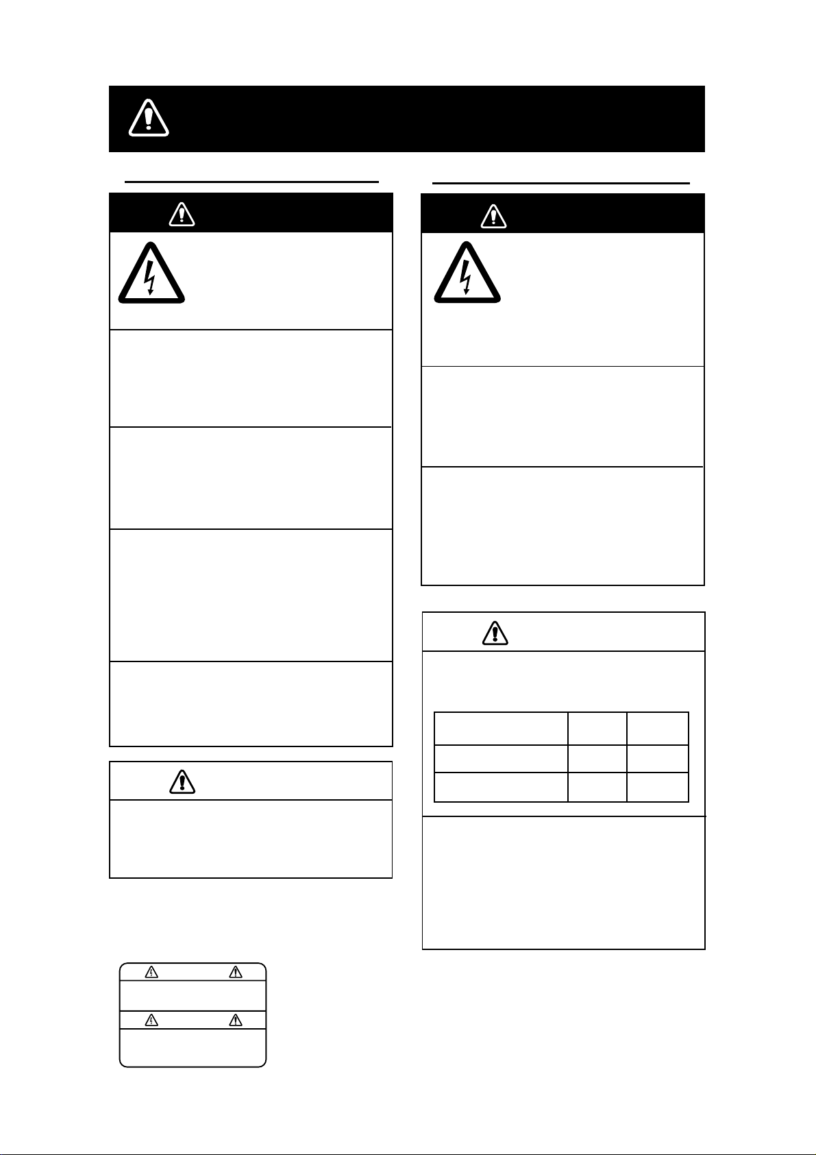
CAUTION
Observe the following compass safe
distances to prevent interference to a
magnetic compass:
Standard Steering
compass compass
LCD Monitor MU-155C
Remote Controller
RMC-200
When lifting the display unit, hold it
together with the hard cover.
Grasping by the hard cover alone may
allow the display unit to fall, resulting in
possible bodily injury or damage to the
equipment.
1.55 m 1.0 m
0.3 m 0.3 m
i
Page 3

TABLE OF CONTENTS
FOREWARD.........................................................................................................iii
SYSTEM CONFIGURATION................................................................................ iv
EQUIPMENT LISTS.............................................................................................. v
1. MOUNTING.......................................................................................................1
1.1 Display Unit..................................................................................................................... 1
1.2 Remote Controller...........................................................................................................4
2. WIRING .............................................................................................................5
3. ADJUSTMENTS................................................................................................ 7
3.1 RGB/DVI Setting .............................................................................................................7
3.2 VIDEO Setting.................................................................................................................9
3.3 Menu Window Setting ...................................................................................................10
3.4 Remote Controller Setting............................................................................................. 12
4. OPERATION.................................................................................................... 13
4.1 Controls.........................................................................................................................13
4.2 Adjusting Display Brilliance............................................................................................15
4.3 Choosing Source for Main Picture................................................................................. 16
4.4 Choosing Source for Picture-in-Picture..........................................................................17
5. MAINTENANCE, TROUBLESHOOTING ....................................................... 18
5.1 Maintenance..................................................................................................................18
5.2 Troubleshooting.............................................................................................................19
5.3 Clearing the Memory.....................................................................................................20
SPECIFICATIONS...........................................................................................SP-1
PACKING LISTS............................................................................................... A-1
OUTLINE DRAWINGS...................................................................................... D-1
INTERCONNECTION DIAGRAM ......................................................................S-1
ii
Page 4

FOREWORD
A Word to the Owner of the MU-155C
FURUNO Elec tric Comp any thanks you for purchasi ng the MU-155 C 15” Multi-Purpose
LCD Display. We are confident you wi ll discover why the FURUNO name h as become
synony m ous with quali ty and reliability.
For over 50 y ear s FURUNO Electric Com pany has enjoyed an enviable r eputation for
quality and r eliability throughout the world. This dedication to excellence is fur thered by our
extensive global network of agents and dealers.
Your equipment is designed and construc ted to meet the rigorous d em ands of the marine
environme nt. However, no machine can perform its int ended function u nless proper ly
inst alled and maintained. Pl eas e c ar efully read and follow the operation, inst allation and
maintenance procedur es s et forth in this manual.
We would appreciate feedback from you, the end-user, about whether we are achievi ng our
purposes.
Thank you for consider ing and purchasing FURUNO.
Features
• Main or r em ot e display f or r adar s , video sounders, sonars, plotter. Compatible
equipment : FAR-21X7 s er ies, MODEL1833C/1833C-B B s er ies (Na vN et),
FCV-1200L/ 1200LM, CH-250, CH-270, CSH-5L/8L, GD/GP - 280/380/680, etc.
• High resolution display of 1024 x 768dot (XGA)
• Brightness of 1,000 cd/m
day and night
• Landscape or ientation
• Wide view ing angle for observation by m or e than one person
• Picture- in-pictur e f unc tion
2
(maximum) and 5 cd/m2 (minimum) for comfortable viewing
iii
Page 5
v
SYSTEM CONFIGURATION
RGB
12-24 VDC
Connect able equipment
Equipment
FR-1500 MK3 series XGA Analog
FCV-1200L/1200LM* VGA Analog, via IF8000
GD/GP-280/380/680 VGA Analog
CH-250 VGA Analog, via IF8000
CH-270 VGA Analog, via IF8000
Resolution Signal
DVI
VIDEO (NTSC/PAL)
Radar, Video Plotter,
Navigator, Video Sounder,
Scanning Sonar, etc.
FAR-2107 series etc.
CCD camera,
Video recorder, etc.
CSH-5L/8L XGA Analog
FSV-24/24S/30/30S SXGA Analog
FR-21X5 series SXGA Analog
FAR-21X7 series SXGA DVI
FEA-2107 SXGA DVI
MODEL 1833C series VGA Analog
MODEL 1833C-BB series VGA Analog
*= Not available for the portrait type.
About the TFT LCD
The TFT LCD is constructed using the
latest LCD techniques, and displays
99.99% of its pixels. The remaining 0.01%
of the pixels may drop out or blink, however this is not an indication of malfunction.
i
Page 6
v
EQUIPMENT LISTS
Standard supply
Name Type Code No. Qty Remarks
Display Unit MU-155C − 1 w/hard cover
Remote Controller RMC-200
Spare Parts*
Installation Materials*
Accessories*
SP19-00201 001-410-490
CP19-00200 000-012-641
FP19-00801 001-410-510
000-012-629
1
1 set
1 set
1 set
Option
Name Type Code No. Qty Remarks
Hanger
Cable Assy
Remote
Controller
* = See packing list at the end of this manual.
FP19-00900 001-410-540
000-146-500
3COX-2P-6C
000-146-501
DVI-D/D SINGLELINK5M 000-149-054
RMC-200 000-012-629
1 w/knob, self-tapping screws
1 Cable length: 5 m
1 Cable length: 10 m
1 Cable length: 5 m
1
Page 7

1. MOUNTING
Refer to the out line drawing at the end of t his manual for mount ing dimens ions.
Note: A grass plate covers the L CD. For thi s reas on, handle t he unit carefully.
1.1 Display Unit
The dis play unit may be mount ed on a desktop ( optional hang er r equired) or f lush mounted
in a panel .
When select ing a mounting location, k eep in mind the f ollowing points:
• Locate the unit out of direct sunlight.
• Select a location w her e the display c an be eas ily view ed and the controls c an be easily
operated.
• Leave suffici ent space around the unit f or s ervi c ing and maintenance. See the outline
drawing for minimum s ervi c ing space.
• The unit weighs 7.9 kg (flush mounting)/9.1 kg (desk top mounti ng) . Be sure the
mounting l oc ation is strong enough to support the weight of the unit.
• Locate the unit away f r om ar eas subject to water splash and rai n.
1
Page 8
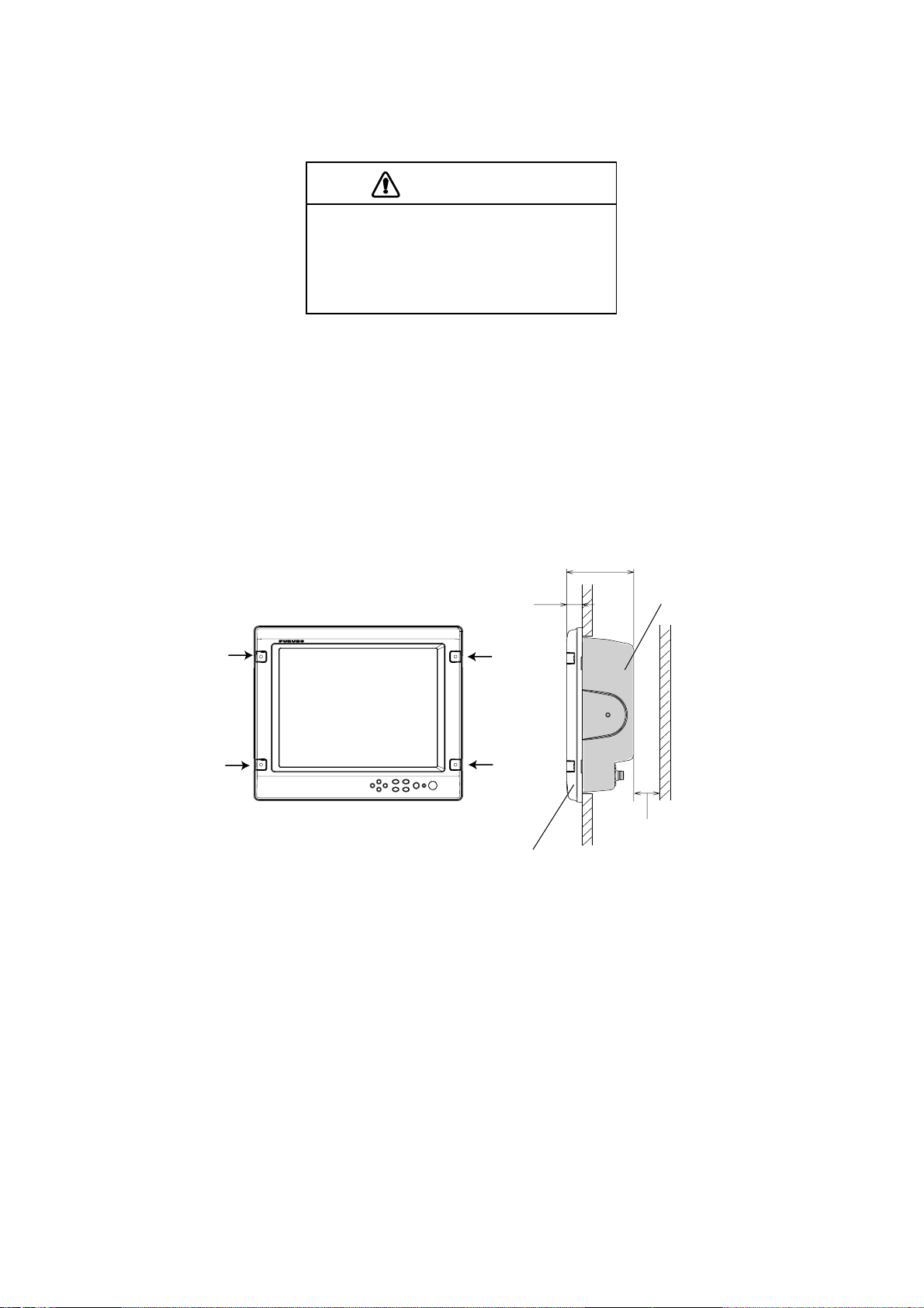
Flush mounting
See the outline drawing at the end of thi s m anual for mounting dimensions.
CAUTION
Hold the hard cover and display unit
together when lifting the display unit.
The display unit may fall out if only the
hard cover is held.
1. Remove the hard cover from the unit.
2. Using the p aper templat e s upplied in t he installation materi als, make a cut out in the
mounting l oc at ion.
3. Set the dis play unit t o the cut out, and fasten it with f our s elf-tappi ng s c r ews (5X40,
supplied as ac ces sories).
Note: Hex head bolts may als o be used to fasten the display unit. However, their lengths
must be 10 mm longer than the wall thick nes s.
130
30
Cosmetic cap
Minimum: 50
Waterproofing: IPX5
Waterproofing: IP20
Mounti ng dimensions
4. Attac h the cosmetic caps (supplied as accessories) to the display unit at the locat ions
shown in the drawing abo ve.
5. Attac h har d c over to protect t he LCD.
2
Page 9
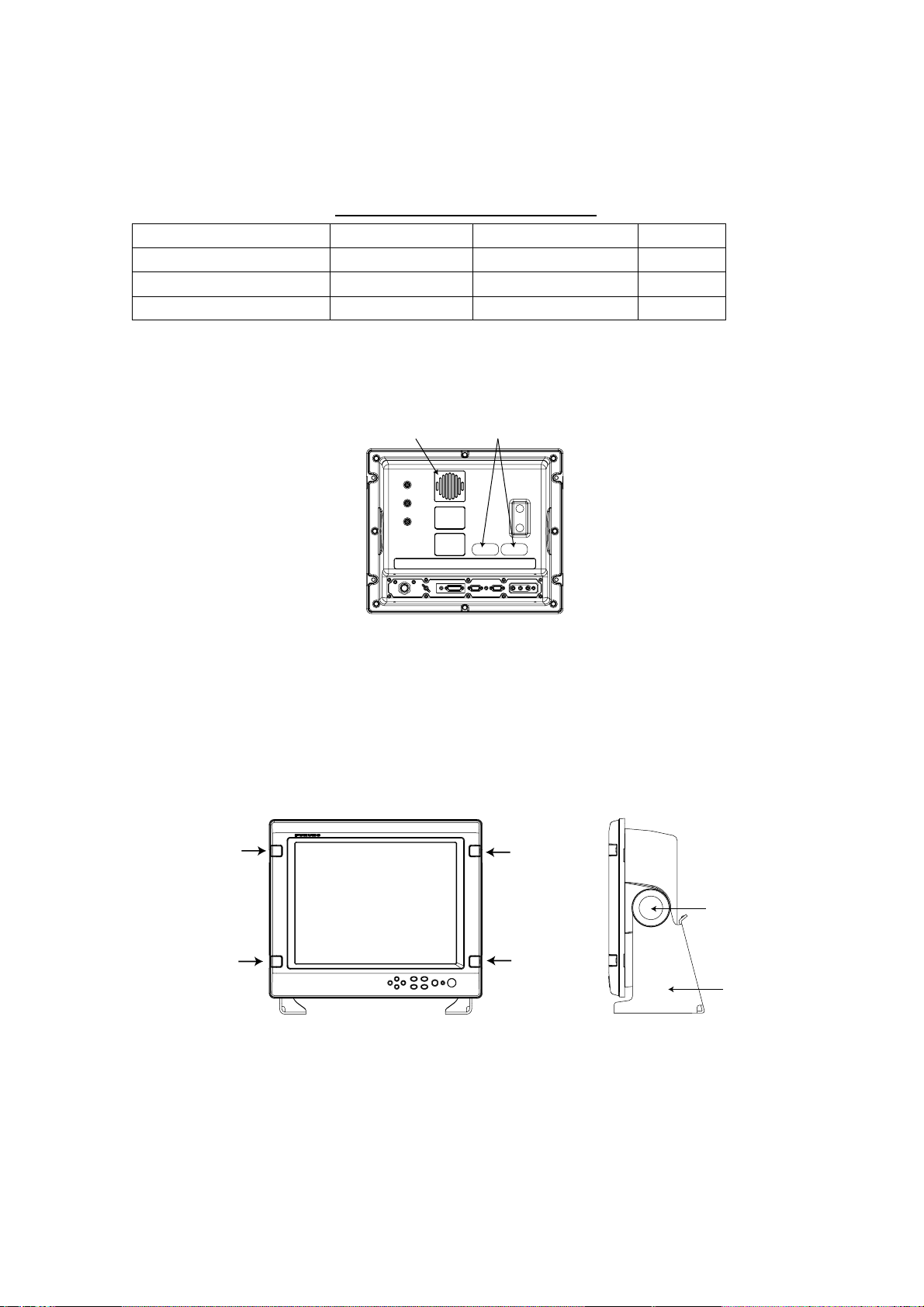
Desktop mounting
The dis play unit can be mounted on a desktop, using the opt ional hanger,
Type: FP19-00900, Code No. : 001-410-540.
Contents of hanger mounting kit
Name Type Code No. Qty
Hanger FP19-00901 001-410-550 1
Knob bolt FP03-09204 008-523-650 2
Self-tapping screw 5x20 000-802-081 4
1. Fasten the hanger to the mo unting locat ion with four self-t apping screws (supplied).
Note: Do not mount the unit where the exha ust or intake vent may be obst r uc t ed.
Exhaust vent
Intake vent
Display unit, rear view
2. Screw k nob bolts in unit.
3. Set unit to hanger, and then tighten knob bol ts.
4. Remove the hard cover from the unit.
5. Attac h the cosmetic c aps (supplied as accessories) to the unit at the locations shown in
the draw ing below.
6. Attac h har d c over to protect the LCD.
Cosmetic cap
Knob bolt
Hanger
Desktop mounting
3
Page 10
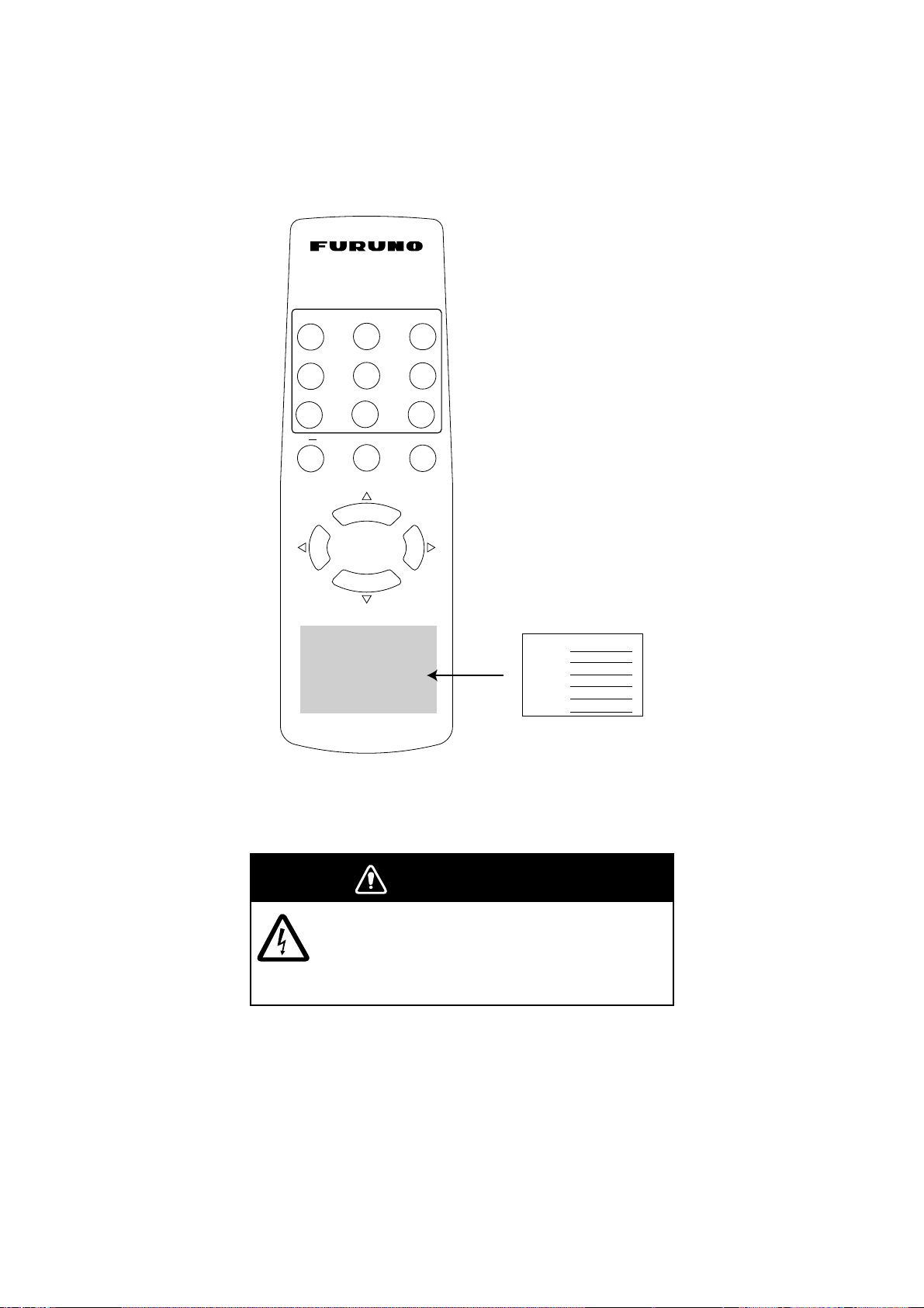
1.2 Remote Controller
Write the device name (ex. “FCV-1200L”) for ea c h “ s ignal” key on the sticker s upplied wit h
the remote cont roller. Attach the sticker to the remote control ler, at the loc ation shown
below.
RGB1
VIDEO1
PIP1 PIP2 PIP3
BRILL
RGB2
VIDEO2
+
DVI
VIDEO3
MENU
RGB 1 :
RGB2 :
DVI :
VIDEO1:
VIDEO2:
VIDEO3:
Sticker
Remote cont r oller RMC-200
WARNING
Ensure battery polarity is correct.
Wrong polarity may cause the batteries to
explode.
4
Page 11
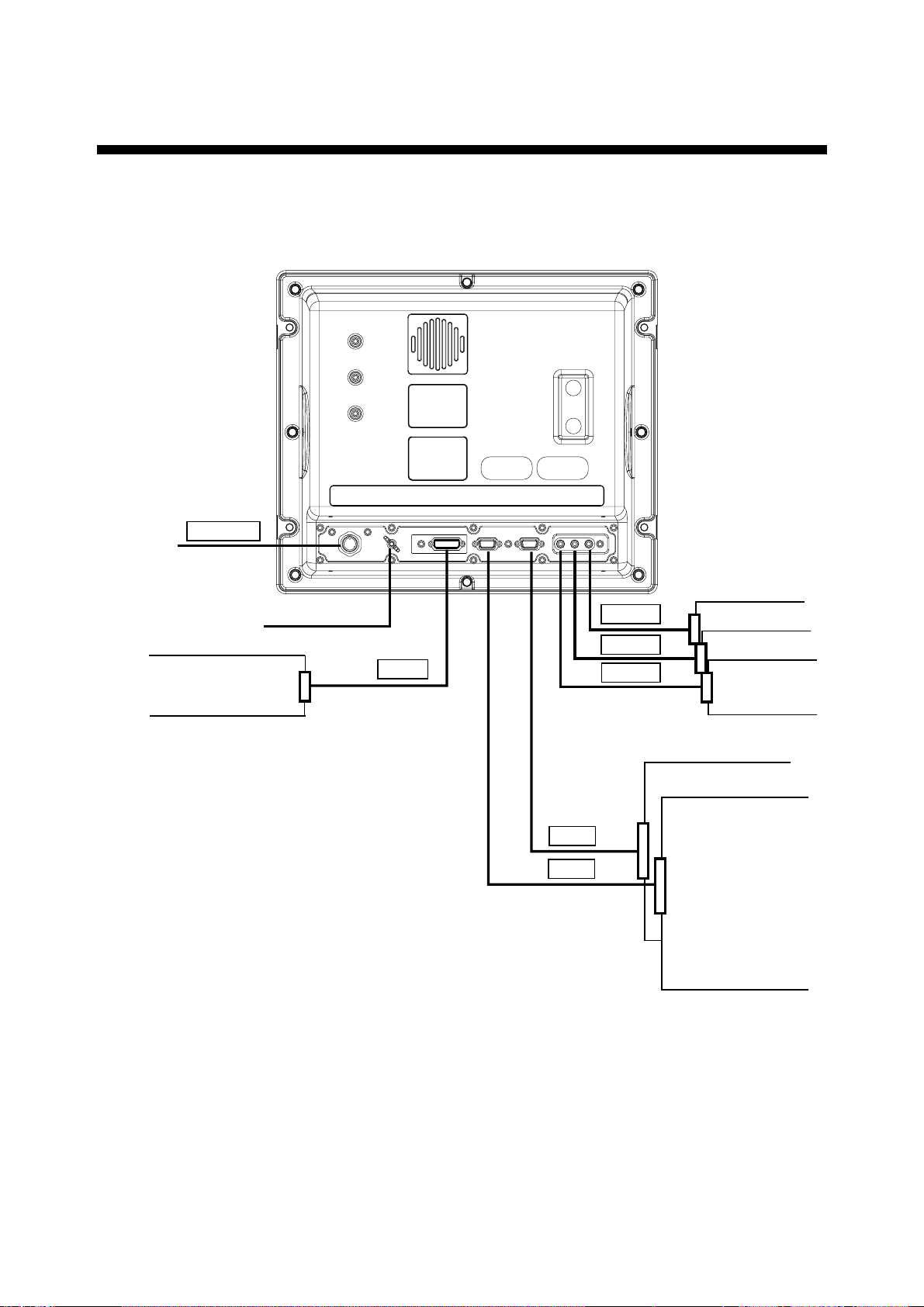
2. WIRING
Connect ext er nal equipment to the MU- 155C by refer r ing to the draw ings below, the table
on the next page and the i nterconnect ion diagram at the back of this manual.
12-24 VDC
12-24VDC
MJ-A3SPF0017-050Z
(Supplied)
Ground terminal
FAR-21X7 series
FEA-2107
DVI-D
DVI-D/D SINGLELINK5M
(Option)
VIDEO3
VIDEO2
VIDEO1
2.5C2V or 3C2V
(Local supply)
RGB2
RGB1
3COX-2P-6C (Option)
CCD camera,
Video recorder, etc.
FCV-1200L/1200LM
CH-250
CH-270
CSH-5L/8L
FSV-24/24S/30/30S
GD/GP-280/380/680
FR-1500 MK3 series
FR-21X5 series
MODEL1833C series
MODEL1833C-BB series
Display unit, rear view
5
Page 12

Port, cable and connectable equipment
Port
Name
12-24
VDC
DVI-D
RGB1
RGB2
VIDEO1
VIDEO2
Used cable
Name Type Code No.
Power
cable
DVI
Cable
Analog
MJ-A3SPF0017-
050Z
DVI-D/D
SINGLELINK5M
3COX-2P-6C
5M
000-138-928 Standard Power source
000-149-054 Option
000-146-500 Option
Standard/
Option
RGB
Cable
3COX-2P-6C
10M
000-146-501 Option
Prepare the following cable locally.
▪ Connector type: RCA (metal), both ends
▪ Cable length: shorter than 10 m
▪ 2.5C2V or 3C2V (Japan Industrial Standard, or the
equivalent) coaxial cable (Impedance: 75 Ω)
Cable 3C2V
Insulator
Shield
Connectable Equipment
PC, FAR-21X7 series,
FEA-2107
FCV-1200L/1200LM,
CH-250, CH-270,
CSH-5L/8L,
FSV-24/24S/30/30S,
GD/GP-280/380/680,
FR-1500 MK3 series,
FR-21X5 series,
Model 1833C series,
Model 1833C-BB series
Video cassette
recorder, CCD camera,
DVD player
Vinyl
sheath
VIDEO3
Conductor
S = 0.19 mm
∅
= 0.5 mm
2
Grounding
Fasten the ground wire (local supply) between the ground terminal on the display unit and
the ship’s superstructure. The length should be as short as possible.
Note: Use a “closed-type” lug (
not use an “open-type” lug (
) to make the ground connection at the display unit. Do
).
6
Page 13

3. ADJUSTMENTS
–
Adjust the MU-155C according to the equipment connected. Note that you can adjust the
display currently selected, at the DISP selection window. (See section 4.3.)
Note: The example screens shown in this manual may not match the screens you see on
your display. The screen you see depends on your system configuration and equipment
settings.
3.1 RGB/DVI Setting
RGB1 and RGB2 screens can be adjusted independently. Also, DVI screen can be adjusted
similarly.
1. Press the [MENU] key to show the main menu.
The main menu is erased automatically with no operation for one minute.
2. Press the [◄] or [►] key to select RGB1, RGB2 or DVI as appropriate.
RGB1 RGB2 DVI VIDEO1 VIDEO2 VIDEO3 OSD SYSTEM
H_SIZE 640
V_SIZE 480
PHASE 16 (1 – 32)
CONTRAST 44 (1 – 64)
H_POSITION 50 (1 – 99)
V_POSITION 25 (1 – 40)
R_LE VEL 31 (1 – 64)
G_LE VE L 31 (1 – 64)
B_LE VEL 31 (1 – 64)
TEMPERATURE 7000K (5500K/6500K/7000K/8000K)
B STRET C H OFF (OFF, 1 – 10)
W STRETCH OFF (OFF, 1 – 10)
DISP MODE FULL (FULL/EVEN/NORMAL)
SHARPNESS 5 (1 – 10)
RGB1 (RGB2) s et ting menu
RGB1 RGB2 DVI VIDEO1 VIDEO2 VIDEO3 OSD SYSTEM
CONTRAST 44 (1
H_POSITION 25 (1 – 50)
V_POSITION 25 (1 – 40)
R_LE VEL 31 (1 – 64)
G_LE VE L 31 (1 – 64)
B_LE VEL 31 (1 – 64)
TEMPERATURE 7000K (5500K/6500K/7000K/8000K)
B STRET C H OFF (OFF, 1 – 10)
W STRETCH OFF (OFF, 1 – 10)
DISP MODE FULL (FULL/EVEN/NORMAL)
SHARPNESS 5 (1 – 10)
64)
DVI setting menu
3. Press the [▲] or [▼] key to select the item to adjust.
4. Press the [◄] or [►] key to adjust.
5. Press the [MENU] key to close the menu.
7
Page 14

Menu item Function Setting range
H_SIZE*** Adjusts the image size horizontally.
V_SIZE*** Adjusts the image size vertically.
PHASE Adjusts the characters and graphic lines. 1-32
CONTRAST Increases or decrease contrast level. 1-64
H_POSITION Moves the image position horizontally. 1-50 (DVI), 1-99 (RGB1, 2)
V_POSITION Moves the image position vertically. 1-40
R_LEVEL Adjusts red color level. 1-64
G_LEVEL Adjusts green color level. 1-64
B_LEVEL Adjusts blue color level. 1-64
TEMPERATURE Adjusts color temperature. 5500K/6500K/7000K/8000K*
B STRETCH Reduces noise on black color. OFF, 1-10
W STRETCH Emphasizes white color. OFF, 1-10
Selects the signal resolution.
FULL: Shows the input signal on entire screen.
DISP MODE
SHARPNESS Sharpens the edge horizontally. 1-10
*: Warm color← 5500K, 6500K, 7000K, 8000K → Cold color
**: Select NORMAL to use the SXGA signal from a radar or scanning sonar. Note that both left
and right edges may be in black. For VGA and XGA signals, FULL and NORMAL are
available.
***: Adjust H_SIZE and V_SIZE properly. Otherwise, unwanted image may appear outside of the
display area.
EVEN: Shows the input signal with original size.
NORMAL: Shows the input signal with same
aspect ratio.
Variable depending on
signal type
FULL/EVEN/NORMAL**
Note: When the characters are not clear, adjust PHASE and SHARPNESS.
8
Page 15

3.2 VIDEO Setting
–
VIDEO1, VIDEO2 and VIDEO3 screens; that is, the picture-in-picture windows can be
adjusted as below.
Picture-in-picture window
Picture- in-pictur e window
1. Press the [MENU] key to show the main menu.
2. Press [◄] or [►] to select VIDEO1, VIDEO2 or VIDEO3 as appropriate.
RGB1 RGB2 DVI VIDEO1 VIDEO2 VIDEO3 OSD SYSTEM
PIP_SIZE 5 (1
CONTRAST 44 (1 – 64)
R_LE VEL 31 (1 – 64)
G_LE VE L 31 (1 – 64)
B_LE VEL 31 (1 – 64)
TEMPERATURE 7000K (5500K/6500K/7000K/8000K)
B STRET C H OFF (OFF, 1 – 10)
W STRETCH OFF (OFF, 1 – 10)
10)
VIDEO1 (2 or 3) s et ting menu
3. Press the [▲] or [▼] key to select the item to adjust.
4. Press the [◄] or [►] key to set.
5. Press the [MENU] key to close the menu.
Menu item Function Available range
PIP_SIZE Adjusts the size of picture-in-picture window.
1(31 mm x 23 mm) -
10 (214 mm x 160 mm)
CONTRAST Increases or decrease contrast level. 1-64
R_LEVEL Adjusts red color level. 1-64
G_LEVEL Adjusts green color level. 1-64
B_LEVEL Adjusts blue color level. 1-64
TEMPERATURE Adjusts color temperature. 5500K/6500K/7000K/8000K
B STRETCH Reduces noise on black color. OFF, 1-10
W STRETCH Emphasizes white color. OFF, 1-10
9
Page 16

3.3 Menu Window Setting
–
3.3.1 Adjusting the menu window
The menu window can be moved and translucentized on the OSD (On Screen Display)
menu.
1. Press the [MENU] key to show the main menu.
2. Press the [◄] or [►] key to select OSD.
RGB1 RGB2 DVI VIDEO1 VIDEO2 VIDEO3 OSD SYSTEM
H_POSITION 15 (1
V_POSITION 37 (1 – 37)
TRANSLUCENT OFF (OFF/ON)
CUSTOM NAME
RGB1 = RGB1______
RGB2 = RGB2______
DVI = DVI_______
VIDEO1 = VIDEO1____
VIDEO2 = VIDEO2____
VIDEO3 = VIDEO3____
29)
OSD menu
3. Press [▲] or [▼] to select the menu item you want to adjust.
4. Press [◄] or [►] to adjust.
5. Press the [MENU] key to close the menu.
Menu item Function Available range
H_POSITION Moves the menu window horizontally. 1-29 (1: left, 29: right)
V_POSITION Moves the menu window vertically. 1-37 (1: up, 37: down)
TRANSLUCENT Translucentizes the menu window. OFF, ON
CUSTOM NAME See the next section.
10
Page 17

3.3.2 Changing the signal name
–
You can change the signal name which is shown on the DISP or PIP window, described in
the next chapter. It is useful to use the name of the device connected (ex. “FCV-1200L”).
For detailed information about these windows, see Chapter 4.
1. Press the [MENU] key to show the main menu.
2. Press the [◄] or [►] key to select OSD.
CUSTOM
NAME area
RGB1 RGB2 DVI VIDEO1 VIDEO2 VIDEO3 OSD SYSTEM
H_POSITION 15 (1
V_POSITION 37 (1 – 37)
TRANSLUCENT OFF (OFF/ON)
CUSTOM NAME
RGB1 = RGB1______
RGB2 = RGB2______
DVI = DVI_______
VIDEO1 = VIDEO1____
VIDEO2 = VIDEO2____
VIDEO3 = VIDEO3____
29)
OSD menu
3. Press the [▲] or [▼] key to select the signal to change its name in CUSTOM NAME
area. In the example above, RGB1 is chosen.
4. Press the [►] key to select the character you want to change. In the example below, “G”
is selected.
CUSTOM NAME
RGB1 = RGB1______
RGB2 = RGB2______
DVI = DVI________
VIDEO1 = VIDEO1____
VIDEO2 = VIDEO2____
VIDEO3 = VIDEO3____
5. Press the [▲] or [▼] key to select appropriate alphanumeric character. In the example
below, “5” is selected.
CUSTOM NAME
RGB1 = R5B1______
RGB2 = RGB2______
DVI = DVI________
VIDEO1 = VIDEO1____
VIDEO2 = VIDEO2____
VIDEO3 = VIDEO3____
6. To change another signal name, press [◄] and then press [▲] or [▼] to select it.
7. Press the [MENU] key to close the menu.
11
Page 18

3.4 Remote Controller Setting
A
A remote controller can be set to be operative with a specific display unit, in the case of
multiple MU-155C display units. Set the remote controller mode desired on the SYSTEM
menu as follows;
1. Press the [MENU] key to show the main menu.
2. Press the [►] key to select SYSTEM.
Display
unit ID
RGB1 RGB2 DVI VIDEO1 VIDEO2 VIDEO3 OSD SYSTEM
INFRARED REMOTE
DEFAULT RESET NO
INFORMATION
RGB1 : 1280x1024 fH: 80KHz fV: 75Hz
RGB2 : 640x480 fH: 31KHz fV: 60Hz
DVI : NO SIGNAL
VIDEO1: NTSC
VIDEO2: PAL
VIDEO3: NO SIGNAL
PROGRAM NO. *****
Remote controller ID square
SYSTEM menu
3. Select INFRARED REMOTE.
4. Point the remote controller toward the display unit, and press any key on the remote
controller. The current setting of remote controller is shown inside the remote controller
setting square.
5. Press the [RGB2] and [BRILL +] keys together on the remote controller to change the
remote controller ID among A, B, C and D.
Your selection appears inside the square.
6. Press the [◄] or [►] key so that the display unit ID is the same as the remote controller
ID in the square.
7. Press the [MENU] key to close the menu.
12
Page 19

4. OPERATION
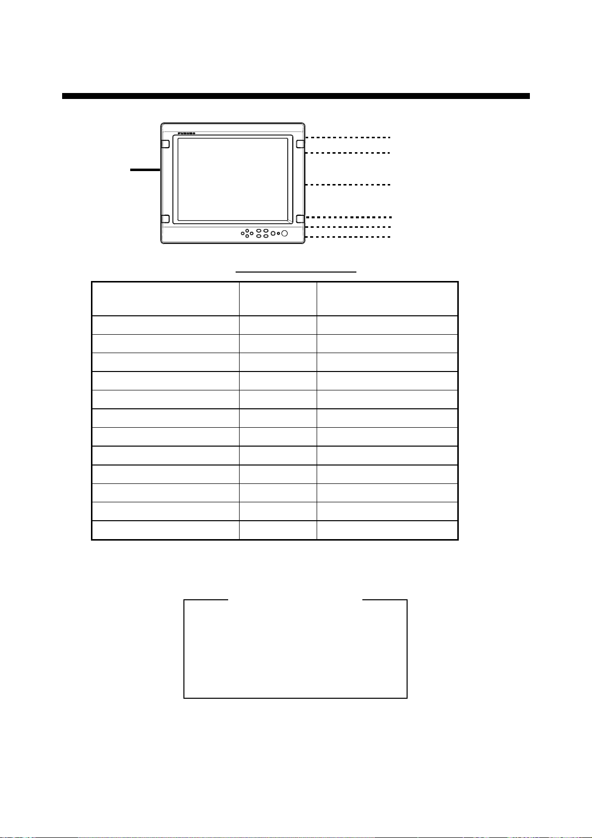
4.1 Controls
Display unit
MENU key
Shows the main menu.
DISP key
Shows the DISPLAY selection window.
Power key
LED
Optical sensor
Arrow keys
Selects menu item.
PIP key
Shows the PIP selection window.
BRILL key
Shows the BRILL adjustment window.
Display unit
Power key: Press the power key (
) to turn the power on or off.
LED: The LED changes color accordi ng t o s ignal status as below.
Green: The selected signal t o be displayed is input correctly from the exter nal device.
Orange: The selected signal t o be displayed is not input from t he ex ternal devic e for five
seconds.
13
Page 20

Remote controller
RGB1
VIDEO1
PIP1 PIP2 PIP3
BRILL
RGB2
VIDEO2
+
DVI
VIDEO3
MENU
Remote cont r oller
Key name Function
RGB1* Shows the RGB1 signal.
RGB2* Shows the RGB2 signal.
DVI Shows the DVI signal.
VIDEO1** Shows the VIDEO1 signal on the entire screen.
VIDEO2** Shows the VIDEO2 signal on the entire screen.
VIDEO3** Shows the VIDEO3 signal on the entire screen.
PIP1*** Shows the VIDEO1 signal in the picture-in-picture window.
PIP2*** Shows the VIDEO2 in the picture-in-picture window.
PIP3*** Shows the VIDEO3 in the picture-in-picture window.
BRILL (+) Increases the display brilliance.
BRILL (-) Decreases the display brilliance.
MENU Shows the main menu.
Arrow keys Selects the menu items.
*: When a picture-in picture window is shown, it remains on the RGB1 (2).
**: When the previous selection is PIP1, 2 or 3, it is erased by pressing these keys.
***: When the previous selection is VIDEO1, 2 or 3, these keys are not available.
For PIP (picture-in-picture), see “3.2 VIDEO Setting”.
14
Page 21

4.2 Adjusting Display Brilliance
The display brilliance can be adjusted as follows.
1. Press the [BRILL] key on the display unit to show the BRILL adjustment window.
2. Press the [◄] or [►] key to adjust the brilliance. (Setting range: 1 to 50)
You can also adjust brilliance by pressing the [BRILL] key.
3. Press the [▲] or [▼] key to close the window.
The window is erased when there is no operation within five seconds.
Note: Avoid excessively low brilliance to prevent display irregularities.
BRILL 50
BRILL w indow
15
Page 22

4.3 Choosing Source for Main Picture
Choose the signal to display on the entire screen as follows:
1. Press the [DISP] key to show the DISP selection window.
Signal names can be changed. For detail, see “3.3.2 Changing the signal name”.
DISP selection window
2. Press the [▲] or [▼] key to select a signal.
You can also select the signal by pressing the [DISP] key continuously.
RGB1-2: The signal from the chosen RGB port is displayed on the entire screen.
DVI: The signal from the DVI port is displayed on the entire screen.
VIDEO1-3: The external video from the appropriate VIDEO port is displayed on the
entire screen.
3. Press the [◄] or [►] key to close the window.
The window is erased when there is no operation within five seconds.
Note: The name of the selected signal appears at the right top corner for five seconds after
the DISP selection window is erased.
RGB1
RGB2
DVI
VIDEO1
VIDEO2
VIDEO3
16
Page 23

4.4 Choosing Source for Picture-in Picture
Choose the source for the picture-in-picture window as follows:
Note: The size of the picture-in-picture window can be adjusted on the VIDEO1, 2 and 3
menus. For details, see section 3.2.
1. With the RGB1, RGB2 or DVI display shown, press the [PIP] key.
The PIP selection window appears. Signal names can be changed. For detail, see “3.3.2
Changing the signal name”.
2. Press the [▲] or [▼] key to select the VIDEO port desired.
VIDEO can be also selected by pressing the [PIP] key continuously. To turn off the
picture-in-picture window, choose OFF.
3. Press the [◄] or [►] key to close the window.
Note: The picture-in-picture window can be moved by pressing the arrow keys when a
menu window is erased.
VIDEO1
VIDEO2
VIDEO3
OFF
PIP window
17
Page 24

5. MAINTENANCE,
TROUBLESHOOTING
WARNINGWARNING
ELECTRICAL SHOCK HAZARD
Do not open the equipment.
Only qualified personnel
should work inside the
equipment.
5.1 Maintenance
Routine maintenance
Regular maintenance is important for good perf or m ance. Check the following on a regular
basis to keep the equipment in good operating condition.
• Check that the c onnectors at the rear of the display uni t are tightly fastened.
• Check the ground wire and gr ound terminal for rust . Clean if nec es s ar y. Confirm that the
ground wire is tightly fastened.
• Remove dust and dirt f r om the display unit and LCD wit h a dry, soft cloth. Do not use
chemical c leaners to cl ean any part of the displ ay unit – they can remo ve p aint and
markings.
• Wipe the LCD car efully to prevent scratc hing, using tissue paper and an LCD c leaner. To
remove dirt or s alt deposits, use an LCD cleaner, wiping slowly with tissue paper so as
to dissolve the dirt or salt. Change paper freque ntly so the salt or dirt will not scratch the
LCD. Do not use s olvents s uc h as thinner, acet one or benzen e for cleani ng.
• Clean the filter at the intake vent regularly. To remove the filter, grasp t he intake vent
with fingers and pull forward. Use an air blower to rem ove dust and dir t from the filter. If
it is p ar ticularly dir ty, wash it in water or mild detergent and then let i t dry. When
reattac hing the filter, be sure it is not caught i n the holes for the i ntake vent.
Intake vent
Display unit, rear view
18
Page 25

Fuse replacement
A
The fuse in the power cable protects the equipment from internal fault and overcurrent. If
the fuse blows, find the c aus e before replac ing it. If the fuse blow s again after replacement,
request ser vic e.
WARNING
Use the proper fuse.
Ship’s power source Rating of fuse
12 VDC 10A
Use of a wrong fuse can cause fire or
damage to the equipment.
24 VDC 5A
Battery replacement
The remote controller has two AA batteries.
If the di stance from w hich the remote
WARNING
controller can be operated has decreased,
change the battery.
Ensure battery polarity is correct.
Note: Replace all bat teries together. Do
Wrong polarity may cause the batteries to
explode.
not mix old and new batteries.
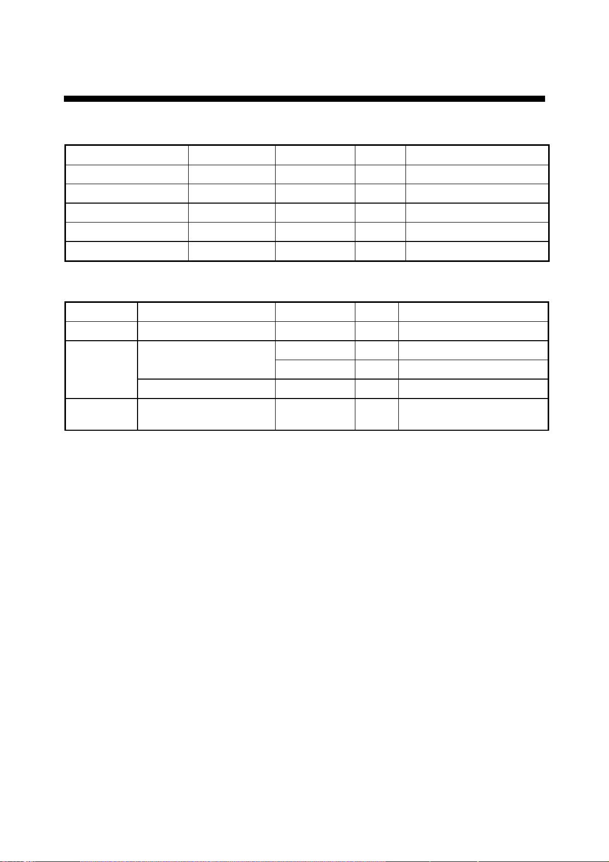
5.2 Troubleshooting
The table below provides troubleshooting procedures to use when no pict ur e appears. If
you cannot res tore the pict ur e, do not att em pt to check ins ide the equipment – there are n o
user serviceable par ts inside. Refer any work to a qualif ied technic ian.
Troubles hooting t able
Reason for no picture Remedy
Ship’s ba tter y vol t a ge too hi g h Chec k ba tter y voltage.
Fuse has blow n. Replace fuse.
Cable between MU-155C and external
equipme nt has loosene d.
Refasten cable.
Power cable has loosened. Refasten cable.
You can confirm which signals are curr ently input in the SYSTEM menu.
RGB1 RGB2 DVI VIDEO1 VIDEO2 VIDEO3 OSD SYSTEM
INFR ARED REMOTE A
DEFAULT RESET NO
INFORMATION
RGB1 : 1280x1024 fH: 80KHz fV: 75Hz
RGB2 : 640x480 fH: 31KHz fV: 60Hz
DVI : NO SIGNAL
VIDEO1: NTSC
VIDEO2: PAL
VIDEO3: NO SIGNAL
PROGRAM NO. *****
SYSTEM menu
19
Page 26

5.3 Clearing the Memory
A
A
You may want to clear the memory to start afresh with default settings. You can do this as
follows:
1. Press the [MENU] key to show the main menu.
2. Press the [►] keys to open the SYSTEM menu.
3. Select DEFAULT RESET by arrow keys.
4. Press the [►] key to select YES.
RGB1 RGB2 DVI VIDEO1 VIDEO2 VIDEO3 OSD SYSTEM
INFRARED REMOTE
DEFAULT RESET YES
All custom settings will be lost.
←key: cancel →key: reset
INFORMATION
RGB1 : 1280x1024 fH: 80KHz fV: 75Hz
RGB2 : 640x480 fH: 31KHz fV: 60Hz
DVI : NO SIGNAL
VIDE O1: NTSC
VIDEO2: PAL
VIDEO3: NO SIGNAL
PROGRAM NO. *****
SYSTEM menu
5. Press the [►] key again to select “reset”.
6. Press the [MENU] key to close the menu.
20
Page 27

SPECIFICATIONS OF MULTI-PURPOSE LCD DISPLAY
MU-155C
1 GENERAL
1.1 Display 15-inch XGA color TFT-LCD, 304 x 228 mm
1.2 Brightness 1,000 cd/m
1.3 Resolution 1024 x 768 (XGA)
1.4 Viewing angle 85° (up/down and left/right)
1.5 Input signal
RGB ports VESA (VGA, SVGA, XGA, SXGA),
(0.7 Vp-p, Synchronization: TTL level)
DVI port VESA (VGA, SVGA, XGA, SXGA)
VIDEO ports NTSC/PAL
2 POWER SUPPLY
12-24 VDC: 7.0-3.0 A
3 ENVIRONMENTAL CONDITION
2
maximum, 5 cd/m2 minimum
3.1 Ambient temperature
Display unit -15°C to +55°C
Remote controller +5°C to +35°C
3.2 Relative humidity 93% at 40°C
3.3 Waterproofing
Display unit Front panel: IPX5, Rear panel: IP20
Remote controller IPX0
3.4 Vibration ● 2 - 5 Hz and up to 13.2 Hz with an excursion of ±1 mm ±10 %
(IEC 60945 ed.4) (7 m/s
2
maximum acceleration at 13.2 Hz)
● 13.2 - 100 Hz with a constant maximum acceleration of 7 m/s
4 COATING COLOR
N3.0
2
SP - 1 E2030S01B
Page 28

This page is intentionally left blank .
Page 29

A-1
A-2
Page 30

Page 31

A-3
Page 32

A-4
Page 33

Y. Hatai
Yoshitos
hiHatai
電子署名者:
Yoshitoshi
Hatai
DN:
cn=Yoshitoshi
Hatai,
o=Furuno,c=JP
日付:
2004.04.21
11:31:19+
09'00'
署名は検証
されていま
せん。
D-1
Page 34

Y.Hatai
Yoshitos
hiHatai
電子署名者:
Yoshitoshi
Hatai
DN:
cn=Yoshitoshi
Hatai,
o=Furuno,c=JP
日付:
2004.04.21
11:31:19+
09'00'
署名は検証
されていま
せん。
D-2
Page 35

ECHO SOUNDER
Y.Hatai
Yoshitos
hiHatai
電子署名者:
Yoshitoshi
Hatai
DN:
cn=Yoshitoshi
Hatai,
o=Furuno,c=JP
日付:
2004.04.21
11:31:19+
09'00'
署名は検証
されていま
せん。
S-1
SONAR
RADAR
PLOTTER
MU-155C
15型カラーLCD表示器
相互結線図
NAME
MULTI-PURPOSE LCD DISPLAY
INTERCONNECTION DIAGRAM
19-024-5100-0C2030-C01-A
レーダー RADAR
43
魚群探知機
*2
3COX-2P-6C
ソナー
レーダー
プロッタ
5m/10m,φ8.5
*2
DVI-D/D SINGLELINK5M
5m,φ7.1
TITLE
名称
*3
*3
9
8
7
6
5
412
MULTI-PURPOSE LCD DISPLAY
15型カラーLCD表示器
RGB2
RGB1
RED
GREEN
GREEN
RED
123
3
BLUE
BLUE
NC
4
GND
GND
GND
GNDNCGND
678
5
GND
GND
GND
121314
NC
HSYNC_NHSYNC_N
NC
13
12
15
NC
VSYNC_NVSYNC_N
NC
15
14
11
10
NCNC
NC
GND
GND
NC
9
11
10
*3
DVI-D
123
RX2+
RX2-
*4
4
5
RX4+
RX4-
RX2_SHIELD
GND
VIN1
VIDEO1
678
DDC_SDA
DDC_SCL
*4
9
1015111213
NC
RX1+
RX1-
VIN2
VIDEO2
RX1_SHIELD
GND
RX3-
RX3+
*4
141716
DDC_GND
DDC_+5V
VIN3
VIDEO3
HPD
GND
18
RXO+
RXO-
12-24VDC
192021
RX5+
RX5-
RXO_SHIELD
DC_P
DC_N
2
1
22
23
RXC+
RXC_SHIELD
SHIELD
3
24
RXC-
*5
IV-8SQ
K.MIYAZAWA
Apr. 21 '04
CHECKED
DRAWN
TAKAHASHI.T
APPROVED
DWG.No.
5A(24V)
2
*2
3COX-2P-6C
5m/10m,φ8.5
*4
*1
コンポジット映像信号用ケーブル
COMPOSITE VIDEO SIGNAL CABLE
MAX.10m
*4
*1
コンポジット映像信号用ケーブル
COMPOSITE VIDEO SIGNAL CABLE
*4
MAX.10m
*1
コンポジット映像信号用ケーブル
COMPOSITE VIDEO SIGNAL CABLE
FUSE 10A(12V)
MAX.10m
5m,φ10
MJ-A3SPF0017-050Z
ECHO SOUNDER
SONAR
RADAR
PLOTTER
12-24 VDC
ソナー
レーダー
プロッタ
魚群探知機
1
ビデオデッキ VIDEO RECORDER
CCDカメラ CCD CAMERA
A
ビデオデッキ VIDEO RECORDER
CCDカメラ CCD CAMERA
B
ビデオデッキ VIDEO RECORDER
CCDカメラ CCD CAMERA
*1)ユーザー手配。
*2)オプション。
*3)工場にて取付済み。
注記
C
*1. USER SUPPLY.
*4)RCAメタルコネクタ、2.5C2Vか3C2Vケーブル推奨。
*5)造船所手配。
NOTE
*2. OPTION.
*3. FITTED AT FACTORY.
RCA METAL CONNECTOR AND CABLE 2.5C2V, 3C2V OR EQUIVALENT.
*4. RECOMMENDED CONNECTOR AND CABLE:
*5. SHIPYARD SUPPLY.
Page 36

9-52 Ashihara-cho,9-52 Ashihara-cho,
A
A
*
00014970000
**00014970000
*
*
00014970000
**00014970000
*
*
OME
20300
A
10
**OME
20300
A
10
**OME
20300
A
10
**OME
20300
A
10
*
Nishinomiya, JapanNishinomiya, Japan
Telephone :Telephone : 0798-65-21110798-65-2111
faxfax 0798-65-42000798-65-4200
ll rights reserved.
ll rights reserved.
::
PUB.No.PUB.No. OME-20300OME-20300
Printed in JapanPrinted in Japan
Your Local Agent/DealerYour Local Agent/Dealer
IRST EDITION :
IRST EDITION : JUNJUN .. 20042004
A1A1 :: JUNJUN .. 23, 200423, 2004
(( YOSHYOSH ))
MU-155CMU-155C
* 0 0 0 1 4 9 7 0 0 0 0 ** 0 0 0 1 4 9 7 0 0 0 0 *
* O M E 2 0 3 0 0 A 1 0 ** O M E 2 0 3 0 0 A 1 0 *
 Loading...