

Page 1

Page 2
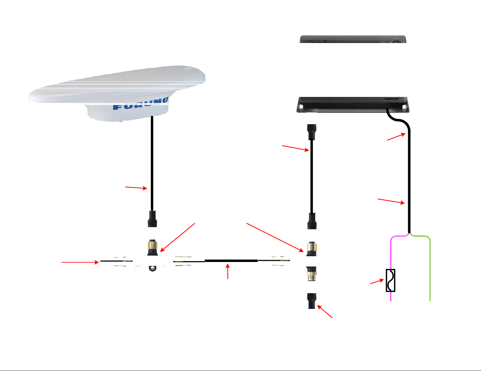
SC30 powered through NN3D
(6 meter antenna cable)
NMEA2000
Terminator
Male
AIR-335-791
No Terminator resistor in
6 meter cable
NMEA2000 Micro drop
cable 6 meter
000-166-887
(supplied)
NMEA2000 Micro
Double-ended cable
Male – Female
1 meter = 000-167-962
2 meter = 000-167-963
6 meter = 000-167-964
NMEA2000 “T”
Connector
AIR-052-531
Fem/Fem/Male
NMEA2000 Micro
Double-ended cable
Male – Female
1 meter = 000-167-962
2 meter = 000-167-963
6 meter = 000-167-964
18 Pin pigtail cable
supplied for use with
Data 2 and 3
000-164-608
This is to supply voltage
for the NMEA2000 Bus.
The minimum voltage is 9
VDC and the maximum is
16 VDC.
(recommend 13.5 VDC)
1 amp Fuse
(local supply)
NMEA2000 Terminator
Female
AIR-335-792
Pink
Data
Port 2
Pin 17
Light
Green
Data
Port 2
Pin 18
Page 3
SC30 powered through NN3D
(15 or 30 meter antenna cable)
NMEA2000 SC30 Backbone
cable
15 meter = 000-166-891
30 meter = 000-166-892
(Terminator resistor included
in both of these cable lengths)
NMEA2000 Field
Connector Female
AIR-335-782
NMEA2000 Micro
Double-ended cable
Male – Female
1 meter = 000-167-962
2 meter = 000-167-963
6 meter = 000-167-964
NMEA2000 “T”
Connector
AIR-052-531
Fem/Fem/Male
18 Pin pigtail cable
supplied for use with
Data 2 and 3
000-164-608
This is to supply
voltage for the
NMEA2000 Bus.
The minimum
voltage is 9 VDC
and the maximum
is 16 VDC.
(13.5 VCD
recommended)
Pin 1 = Shield
Pin 2 = Red
Pin 3 = Black
Pin 4 = White
Pin 5 = Blue
The Purple, Yellow and Green wires are not used for
this connection. They need to be cut back, isolated
and taped so they don’t short to any other wires and
cause equipment damage.
NMEA2000 Terminator
Male
AIR-335-791
1 amp Fuse
(local supply)
Pink
Data
Port 2
Pin 17
Light
Green
Data
Port 2
Pin 18
Page 4

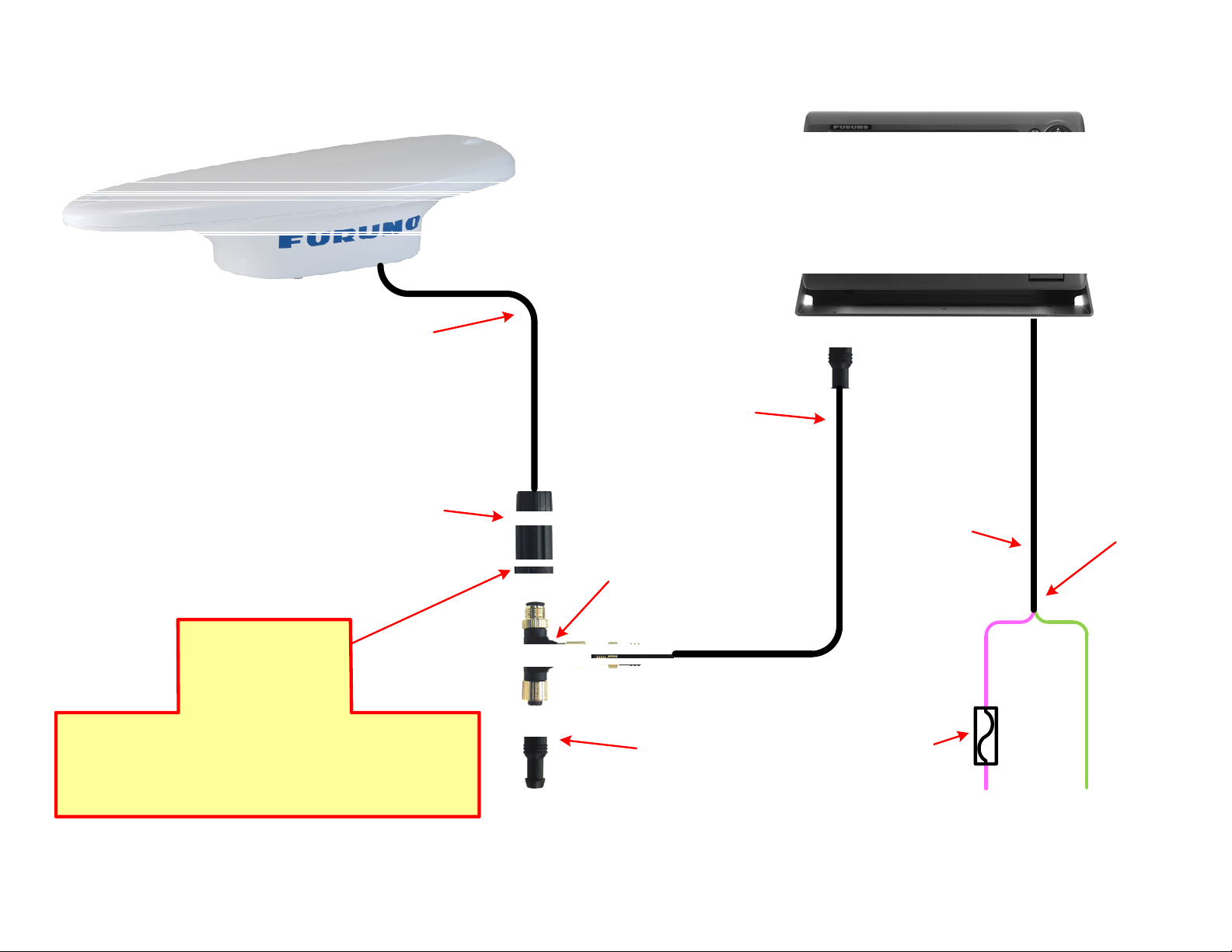
NMEA2000 Micro drop
cable 6 meter
000-166-887
(supplied)
No Terminator resistor
in 6 meter cable
Cut the NMEA2000 connector off of SC30
cable and connect the wires to the green
NMEA2000 connector inside the DRS2D
Match the wire colors to the colors shown
in the DRS Connector close-up.
SC30 connection to DRS Dome and NavNet 3D
(6 meter cable)
Use the included 3 hole
gasket for this
installation application.
or DRS4D.
Inside DRS2D and DRS4D
DRS Connector
close-up
123456
Ethernet and power
Install (2) 120 Ω resistors in
parallel
000-167-746
(1 is supplied)
Page 5

NMEA2000 SC30 Backbone
cable
15 meter = 000-166-891
30 meter = 000-166-892
(Terminator resistor included
in both of these cable
lengths)
Connect the wires to the green NMEA2000
Match the wire colors to the colors shown
The Purple, Yellow and Green wires in this
cable are not used for this connection. They
need to be cut back, isolated and taped so
they don’t short to any other wires and
SC30 connection to DRS Dome and NavNet 3D
(15 or 30 meter antenna cable)
Use the included 3 hole
gasket for this
installation application.
terminal inside the DRS Dome.
in the DRS Connector close-up.
DRS Connector
cause equipment damage.
Inside DRS2D and DRS4D
close-up
12 34 5 6
Ethernet and power
Terminator Resistor
120 Ω
000-167-746
(supplied)
Page 6

NMEA2000 Micro
drop cable 6 meter
000-166-887
(supplied)
No Terminator resistor in 6
meter cable
SC30 connection to DRS Gearbox and NN3D
(6 meter cable)
Use the included 3 hole
gasket for this
installation application.
Cut NMEA2000 connector off of cable
and connect the wires to the gray
NMEA2000 terminal inside the DRS
Gearbox.
Match the wire colors to the colors shown
in the DRS Connector close-up.
Install (2) 120 Ω resistors in
DRS Connector
close-up
parallel
000-167-746
(1 is supplied)
Inside DRS Gearbox
Attach crimp-lug to shield
wire in NMEA2000 cable and
fasten to screw on radar T/R
chassis shown in image
above and below.
Ethernet
Page 7

NMEA2000 SC30
Backbone cable
15 meter = 000-166-891
30 meter = 000-166-892
(One terminator resistor is
embedded in the SC30
connector end of these
optional cables)
SC30 connection to DRS Gearbox and NN3D
(15 or 30 meter antenna cable)
Use the included 3 hole
gasket for this
installation application.
Connect the wires to the gray NMEA2000
terminal inside the DRS Gearbox.
Match the wire colors to the colors shown
in the DRS Connector close-up.
The Purple, Yellow and Green wires in this
cable are not used for this connection.
They need to be cut back, isolated and
taped so they don’t short to any other
wires and cause equipment damage.
Terminator Resistor
000-167-746
(supplied)
DRS Connector
close-up
120 Ω
Inside DRS Gearbox
Attach crimp-lug to shield
wire in NMEA2000 cable and
fasten to screw on radar T/R
chassis shown in image
above and below.
Ethernet/Power
Page 8

No Terminator
resistor in 6 meter
cable
NMEA2000 Micro drop
cable 6 meter
000-166-887
(supplied)
Appropriate fuse
or circuit breaker
SC30 to FI5002 with FI505 instrument with NN3D
(6 meter antenna cable)
NMEA2000 Micro Drop
cable
6 meter
000-166-945
Cut NMEA2000 connector off of
cable and connect the wires to one
of the 6 drop ports inside the
FI-5002.
Match the wire colors to the colors
shown on the drop connector.
FI-5002 Junction Box
Connect to any of the 6
drop connection ports
inside the FI-5002. Match
the wire colors to the
colors shown on the drop
connector. (same as
shown for the backbone
connector)
jumpers to ON to use the FI5002
NMEA2000 Micro Drop
cable
1 meter = 000-167-965
2 meter = 000-167-966
6 meter = 000-167-967
Set both Terminal Resistor
as the NMEA2000 backbone.
ON:
OFF:
This is to supply voltage
for the NMEA2000 Bus.
The minimum voltage is 9
VDC and the maximum is
16 VDC.
(13.6 VDC recommended)
Drop
connector
1
2345
Page 9

NMEA2000 SC30 Backbone
cable
15 meter = 000-166-891
30 meter = 000-166-892
(One terminator resistor is
embedded in the SC30
connector end of these
optional cables)
Appropriate fuse
or circuit breaker
SC30 to FI5002 with FI505 instrument with NN3D
(15 or 30 meter antenna cable)
NMEA2000 Micro
Drop cable
6 meter
000-166-945
Connect the wires to either of the
2 larger backbone connectors
inside the FI-5002.
Match the wire colors to the colors
shown on the backbone connector.
The Purple, Yellow and Green wires
in this cable are not used for this
connection. They need to be cut
back, isolated and taped so they
don’t short to any other wires and
cause equipment damage.
FI-5002 Junction Box
Connect to any of the 6
drop connection ports
inside the FI-5002. Match
the wire colors to the
colors shown on the drop
connector. (same as
shown for the backbone
connector)
jumper to ON because the 15m
NMEA2000 Micro
Drop cable
1 meter = 000-167-965
2 meter = 000-167-966
6 meter = 000-167-967
Set only 1 Terminal Resistor
and 30m cables each have a
resistor built-in.
ON:
OFF:
This is to supply voltage for
the NMEA2000 Bus. The
minimum voltage is 9 VDC
and the maximum is 16 VDC.
(13.6 VDC recommended)
Backbone connector
2
1
4
3
5
 Loading...