

Page 1

Page 2

C
(
)
9-52, Ashihara-cho,
Nishinomiya, Japan
Telephone: 0798-65-2111
Telefax: 0798-65-4200
Your Local Agent/Dealer
All rights reserved.
Print ed in Japa n
FIRST EDITION : OCT. 1998
G : APR. 4, 2000
PUB. No. OME-56093
TENI
IB-681
Page 3
SAFETY INSTRUCTIONS
WARNING
Do not place liquid-filled containers on
the top of the equipment.
Fire or electrical shock can result if a liquid
spills into the equipment.
Immediately turn off the power at the
switchboard if the equipment is emitting
smoke or fire.
Continued use of the equipment can cause
fire or electrical shock. Contact a FURUNO
agent for service.
Make sure no rain or water splash leaks
into the equipment.
Fire or electrical shock can result if water
leaks in the equipment.
Keep heater away from equipment.
A heater can melt the equipment’s power
cord, which can cause fire or electrical
shock.
CAUTION
A warning label is attached to the equipment. Do not remove the label. If the
label is missing or illegible, contact
a FURUNO agent or dealer.
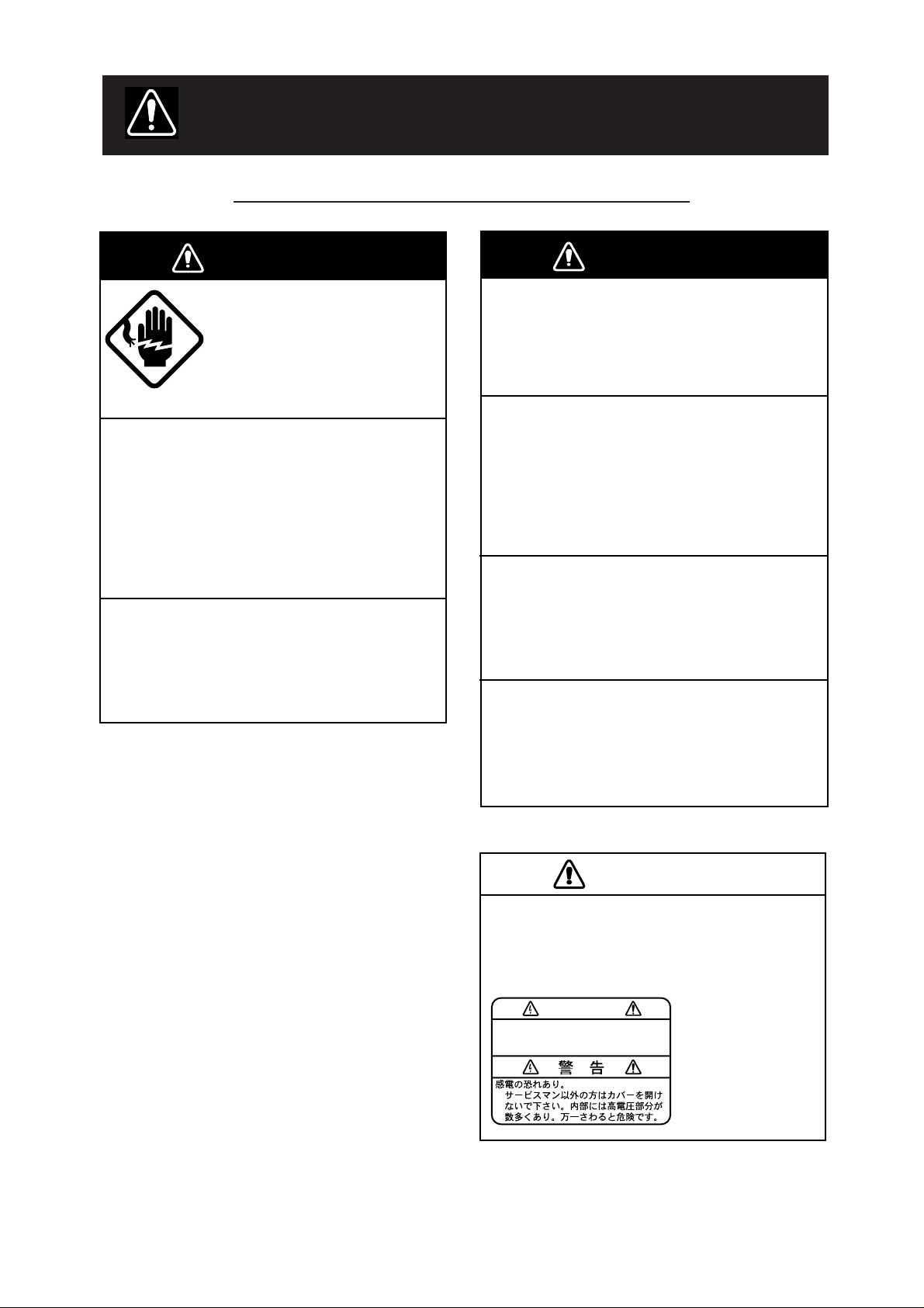
WARNING
To avoid electrical shock, do not
remove cover. No user-serviceable
parts inside.
Name: Warning Label (1)
Type: 86-003-1011-0
Code No.: 100-236-230
Safety Information for the Operator
WARNING
ELECTRICAL SHOCK HAZARD
Do not open the equipment.
Only qualified personnel
should work inside the
equipment.
Immediately turn off the power at the
switchboard if water leaks into the
equipment or something is dropped in
the equipment.
Continued use of the equipment can cause
fire or electrical shock. Contact a FURUNO
agent for service.
Do not disassemble or modify the
equipment.
Fire, electrical shock or serious injury can
result.
iiiiiiiiiiiii
i
Page 4
Safety Information for the Installer
WARNING
ELECTRICAL SHOCK HAZARD
Do not open the equipment
unless totally familiar with
electrical circuits and
service manual.
Only qualified personnel
should work inside the
equipment.
Turn off the power at the switchboard
before beginning the installation.
Fire or electrical shock can result if the
power is left on.
Do not install the equipment where it
may get wet from rain or water splash.
Water in the equipment can result in fire,
electrical shock or equipment damage.
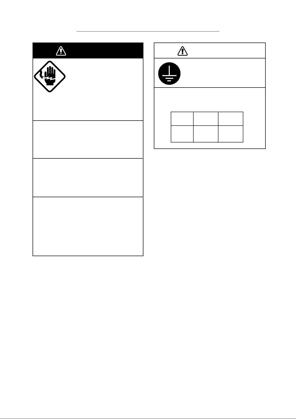
CAUTION
Ground the equipment to
prevent electrical shock and
mutual interference.
Observe the following compass safe
distances to prevent deviation of a
magnetic compass:
Standard Steering
Compass Compass
HSD
Modem
1.2 m 0.9 m
Be sure that the power supply is
compatible with the voltage rating of
the equipment.
Connection of an incorrect power supply
can cause fire or equipment damage. The
voltage rating of the equipment appears
on the label above the power connector.
ii
iiiiiiiiiiiiiiiiiiiiiiiiii
Page 5

TABLE OF CONTENTS
INTRODUCTION.................................................................................v
EQUIPMENT LIST ............................................................................. vi
SYSTEM CONFIGURATION.............................................................viii
1. OVERVIEW
1.1 Control Description...........................................................................................................1
1.1.1 Front panel..............................................................................................................1
1.1.2 Rear panel ..............................................................................................................2
2. SETTINGS
2.1 Switch Panel Settings ......................................................................................................3
2.1.1 Data rate .................................................................................................................3
2.1.2 DIP switches ...........................................................................................................3
2.2 OID/DID and IMN Settings...............................................................................................5
2.3 Terminal Unit Settings ......................................................................................................5
2.4 Registering, Deleting Subscriber Number........................................................................5
2.4.1 Registering subscriber number...............................................................................6
2.4.2 Deleting subscriber number....................................................................................6
2.4.3 Confirming subscriber number................................................................................6
2.4.4 Status display on the terminal unit..........................................................................6
3. OPERATION
3.1 Calling ..............................................................................................................................7
3.1.1 Automatic HSD call.................................................................................................7
3.1.2 Manual call..............................................................................................................8
3.2 Receiving .........................................................................................................................9
3.2.1 Automatic call mode and receiving operation .........................................................9
3.2.2 Receiving and automatic data rate switching .......................................................10
3.3 V.25bis Command, Indication ........................................................................................10
3.4 Call Sequence................................................................................................................12
3.4.1 Direct call setup sequence....................................................................................12
3.4.2 Address call setup sequence................................................................................13
3.4.3 Manual call setup sequence .................................................................................14
3.4.4 Automatic call clear sequence ..............................................................................15
3.4.5 Call clear sequence from land ..............................................................................15
3.4.6 Manual call clear sequence ..................................................................................16
iii
Page 6

4. MAINTENANCE & TROUBLESHOOTING
4.1 Maintenance...................................................................................................................17
4.1.1 Cleaning................................................................................................................17
4.1.2 Resetting the circuit breaker .................................................................................17
4.2 Self Test at Terminal Unit ...............................................................................................17
4.3 Troubleshooting for the User..........................................................................................18
5. INSTALLATION
5.1 Mounting ........................................................................................................................19
5.1.1 Mounting location..................................................................................................19
5.1.2 Mounting procedure..............................................................................................19
5.2 Wiring.............................................................................................................................20
5.2.1 Wiring between HSD modem and router ..............................................................20
5.2.2 Modifying the RF CONV board in the communication unit ...................................21
5.2.3 Wiring between HSD modem and communication unit ........................................26
5.2.4 Ground..................................................................................................................26
APPENDIX Usage Tips
Communication with other makes of Inmarsat-B terminals..................................................27
Landline................................................................................................................................27
Propagation delay ................................................................................................................27
TCP/IP protocol....................................................................................................................27
Router setting for network connection .................................................................................27
Network configuration ..........................................................................................................28
Synchronous-asynchronous adapter ...................................................................................29
Land earth station ................................................................................................................30
SPECIFICATIONS ..................................................................................................SP-1
OUTLINE DRAWING...............................................................................................D-1
INTERCONNECTION DIAGRAM ...................................................................... S-1
SCHEMATIC DIAGRAM ........................................................................................ S-2
INDEX......................................................................................................................Index-1
Declaration of conformity to type
iv
Page 7

INTRODUCTION
FURUNO Electric Company thanks you for selecting the IB-681 High Speed Data (HSD)
Modem. We are confident you will discover why FURUNO has become synonymous with
quality and reliability.
For over 50 years FURUNO Electric Company has enjoyed an enviable reputation for
excellent marine electronics equipment. This dedication to excellence is furthered by our
extensive global network of agents and dealers.
The IB-681 is designed and constructed to meet the rigorous demands of the marine
environment. However, no machine can perform its intended function unless properly installed and maintained. Please carefully read and follow the recommended procedures for
installation, operation and maintenance to get maximum performance from this equipment.
Features
The IB-681 provides global, satellite-based high speed duplex 56 or 64 Kbps data via
ISDN. High speed data services will be useful to companies and organizations with large
amounts of data to transmit.
• Automatic, manual calling
• LEDs show equipment status
• Simple operation
• DIP switches and data rate switch set operation parameters
Notice
FURUNO will assume no responsibility
for security-related problems.
Network configuration depends on
application, number of terminals used,
shipboard network and land network.
Generally, setup is done on the user’s
equipment. For details on network setup
contact the network manager.
v
Page 8

EQUIPMENT LIST
Complete Set
emaNepyT.oNedoCytQskrameR
tinUmedoMDSH186-BI1
00610-61PC263-340-000
noitallatsnI
slairetaM
01610-61PC163-340-000
Installation Materials CP16-01601
emaNepyT.oNedoCytQ
tceleS
eno
89/7erofebderutcafunam
tinu.mmoc18MOCLEFroF
retfadna89/7derutcafunam
)084-344-400(10610-61PC
)009-244-400(20610-61PC
)059-244-400(50610-61PC
)084-344-400(10610-61PC
)009-244-400(20610-61PC
)064-344-400(30610-61PC
)059-244-400(50610-61PC
eeS
noitallatsni
tinu.mmoc18MOCLEFroF
slairetam
wolebstsil
.sliatedrof
rotcennoC)C8D(20-05232-EJ71649-021-0002
rotcennoC)C8D(20-07332-EJ71401-141-0002
.yssArotcennoC0-7720S61564-141-0001
.yssAelbaC0001-2XU55-P-CNB315-141-0003
.yssAelbaCssenraH2-375-EJ71415-141-0001
partSreppoC1300-300-50013-003-0951
wercSgnippaT403SUS02X6480-208-0004
Installation Materials CP16-01602
emaNepyT.oNedoCytQ
.yssArotcennoC60610-61PC019-244-4001
.yssAelbaCP2PMS-002L-P5HP855-141-0001
.yssAelbaCP2RMS-003L-P2HP955-141-0001
wercSdaehnaP8X4M544-188-0004
vi
Page 9

Installation Materials CP16-01603
emaNepyT.oNedoCytQ
draoBVNOCFR0310P61041-144-4001
lenaPraeR5-3102-110-61596-542-0011
Installation Materials CP16-01605
emaNepyT.oNedoCytQ
MORdemmargorP15010561MORP005-144-4001
MORdemmargorP16010561MORP015-144-4001
Optional Equipment
emaNepyT.oNedoCytQskrameR
elbaCnoitcennoC
tiK
91-61PC011-744-4001
ssenraH2-375-EJ71
,)801-721-000(
005-2XU55-P-CNB
,)969-141-000(
m5ybnoisnetxerof
vii
Page 10

SYSTEM CONFIGURATION
ANTENNA
UNIT
IB-181
Antenna cable
COMMUNICATION
UNIT
IB-281
Coaxial cable
HSD
MODEM
IB-681
Serial cable
(9 pin connector)
Serial straight cable
(25 or 37 pin connector)
NETWORK
ROUTER
(HSD TERMINAL)
PC
LAN
PC
: Local supply
: FELCOM 81
viii
Page 11
1. OVERVIEW
1.1 Control Description
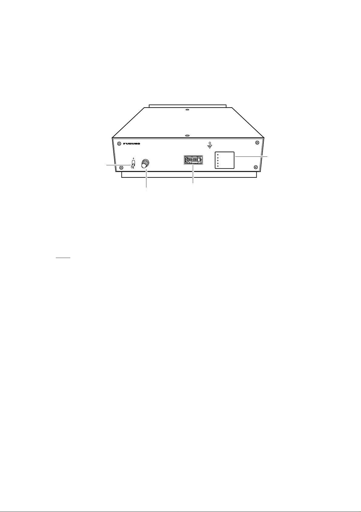
1.1.1 Front panel
DIMMERPOWER
ON
POWER
switch
OFF
INMARSAT-B
HIGH SPEED DATA MODEM
POWER
SYNC
TX (64K)
TX (56K)
FAIL
LED
DIMMER
control
Switch panel
(cover removed)
Figure 1 IB-681, front view
POWER switch: T urns the power on/off. Flip up to turn the power on; flip down to turn the
power off. After turning on the power, all status LEDs light for about 20 seconds. Then all
LEDs except POWER go off about 10 seconds later. Turn on the IB-281 about 30 seconds after turning on the IB-681, otherwise the IB-281 may display “HSD Fault.” If the FAIL
lamp on the IB-281 goes off then operation is normal.
DIMMER control: Adjusts the illumination of the status LEDs.
Switch panel: Contains eight DIP switches and the Data Rate switch which set operation
parameters. See page 3 for details.
Status LEDs: Show equipment status.
POWER: Lights when the power is turned on.
SYNC: Lights, during HSD communications, when satellite signal becomes synchro-
nized.
TX (64K): Lights when data rate is 64 Kbps.
TX (56K): Lights when data rate is 56 Kbps.
FAIL: Lights for communication error.
Note: TX LED on IB-281 dose not light during HSD communications.
1
Page 12

1.1.2 Rear panel
HSD DATA 2
HSD DATA 1
HSD DATA1 HSD DATA2
TX IF RX IF
TX IF
REF
REF
RX IF
HSD CTRL
AC100-220V
100-220 VAC
HSD CTRL
BREAKER
Earth terminal
Breaker (1A)
Figure 2 IB-681, rear view
HSD DATA 1: RS-232 interface connector
HSD DATA 2: RS-449 interface connector
HSD CTRL: Conducts control data communications between communication unit and
HSD modem.
Breaker: The red button pops out when overcurrent flows inside the equipment. In this
case, find the cause of the overcurrent and push the button.
100-220 VAC: Connection of 100/220 VAC power.
REF: Receives reference signal from the communication unit.
RX IF: Receives IF signal from the communication unit.
TX IF: Sends IF signal to the communication unit.
2
Page 13

2. SETTINGS
2.1 Switch Panel Settings
Communication parameters are set with the switches in the switch panel. Unfasten two
screws to access the switches. Note that it is not necessary to turn off the IB-681 to
access the switches.
1 2 3 4
ON
5 6 7 8
Data Rate
64K
56K
: Factory setting
Figure 3 Switch panel
2.1.1 Data rate
Set the data rate according to land line/network. The default setting is 64k (64 Kbps). 56k
is for USA ISDN circuit, for example. Data rate cannot be change after connecting with a
subscriber.
2.1.2 DIP switches
Table 1 DIP switch functions
.oNWSnoitcnuFFFONO
1WSllaccitamotuAllactceriDllacsserddA
2WSecafretnilanimreT944-SR232-SR
3WS
4WStamrofdnammoCCLDHCSB
5WStamrofretcarahCytirapon/tib8ytirapddo/tib7
6WSdesutoN
7WSdesutoN
8WSdesutoN
atadcitamotuA
gnihctiwsetar
ONSEY
SW1: Automatic call mode
OFF: Call starts with reception of DTR signal from HSD terminal.
ON: Call starts when subscriber number from the HSD terminal is loaded on the TxD line.
3
Page 14

SW2: Terminal interface
g
g
y
y
Interface with HSD terminal.
OFF: RS-449 (D-SUB 37 pin connector).
ON: RS-232 (D-SUB 25 pin connector).
SW3: Automatic data rate switching
Determines whether to receive data at data rate other than what is set with the Data Rate
switch in the switch panel.
OFF: Prevents reception of data received at data rate other than which is set with the data
rate switch.
ON: Enables reception of data received at data rate other than which is set with the data
rate switch.
SW4: Command format
Sets command format to the HSD modem, and is only effective when SW1 is set for
address call (ON). Set according to specification of HSD terminal.
OFF: HDLC format
ON: BSC format
HDLC command format
galFrddAlortnoCnoitacidnI/dnammoCSCFgalF
lFgalF:ga
dleiFsserddA:sserddA
dleiFlortnoC:lortnoC
emarF:SCFecneuqeSkcehC
tiraP
lnodedda
BSC command format
NYSNYSNYSXTSnoitacidnI,dnammoCXTE
H61:NYS
H20:XTS
H30:XTE
7b·····1b0b
01111110
11111111
10001001
.lanimretDSHeht
is
nolatsriftnes)0b(.noitacidni,dnammocot
.eriwlan
otlanimretDSHmorftnesNYSeerhT
eraNYSowtylno,revewoH.medomDSH
dnamedomDSHehtneewtebyrassecen
.enillangisehtgnolatnestsrifsiBSL.sretcarahclortnocesehtotdeddaoslasiytiraP
SW5: Character format
Sets character format to the HSD modem, and is only effective when SW1 is set for address call (ON). Set according to specification of HSD terminal.
OFF: 8 bit, no parity
ON: 7 bit, even, odd parity
4
Page 15
2.2 OID/DID and IMN Settings
OID/DID and IMN are set on the communication unit, usually at the time of installation.
The telephone for HSD calling is alos set by the installing technician. For more information, contact a FURUNO dealer or agent.
2.3 Terminal Unit Settings
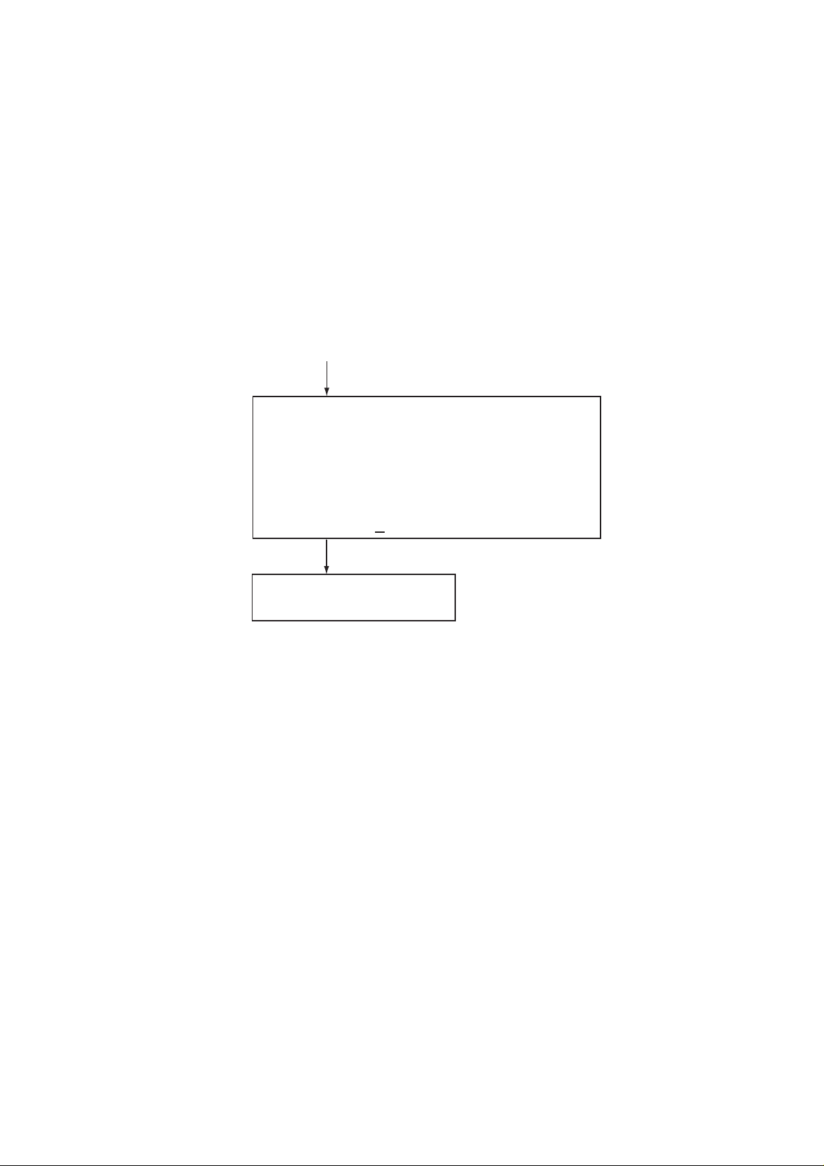
“9: HSD” is added to the Terminal Setup menu on the terminal unit. Additionally, the HSD
is provided with the lock switch function, which you may set it as shown below.
Press [2], [Enter].
[Terminal setup]
1: Tel No.1 7: Data
2: Tel No.2 8: Telex
3: Tel No.3 9: HSD
4: Tel No.4
5: Tel No.5
6: Tel No.6
E: Exit
Enter JOB No. 9
Press [9], [2].
[HSD]
Key Lock: Ignore/Valid
Ignore: Lock switch setting ignored;
receive capability.
Valid: Lock switch setting followed;
cannot transmit when lock
switch is in "disable" position.
Figure 4 Terminal setup menu
5
Page 16

2.4 Registering, Deleting Subscriber Number
2.4.1 Registering subscriber number
Register subscriber number as follows with the No.1 telephone. The subscriber number
may contain 20 digits (*, # cannot be registered). The number can be confirmed by printing
the status display.
1. Pick up the handset of the No.1 telephone and confirm dial tone.
2. Dial subscriber’s no. as follows:
* 5 1 * a a a 0 0 b b x x x x x x x x x #
Subscriber’s Number
3. Confirm dial tone (See table 2).
2.4.2 Deleting subscriber number
Country Code
Automatic Dialing
Land Earth Station (LES)
Prefix (64k) for HSD call
1. Dial * 5 1 * #.
2.4.3 Confirming subscriber number
HSD communications settings (HSD settings input to the communcation unit) are contained on the status monitor which can be printed from the No.1 telephone.
1. Pick up the handset of the No. 1 telephone.
2. Dial * 9 6 # to print the status monitor.
.
.
.
Prefix Code:
HSD Destination: XXXXXXXXXXXXXXX
2.4.4 Status display on the terminal unit
The status display shows HSD state. You can print it from the terminal unit. Sample HSD
status indications are as below.
RX Signal Level (HSD) ...
RX IF AGC Level (HSD) ...
2nd Local (HSD) ...
6
Page 17

3. OPERATION
3.1 Calling
An HSD call may be made automatically or manually.
3.1.1 Automatic HSD call
All automatic HSD calls are carried and terminated from the HSD terminal. Automatic
HSD calls begin when the DTE raises the DTR line in the serial connector. The Inmarsat
terminal dials the pre-programmed number. Upon answer by the called system the HSD
port is enabled and data transfer can take place.
Automatic HSD calls fall into two categories: direct call and address call. The category
may be selected with DIP switch SW1: turn off the switch (default setting) for direct call;
turn on the switch for address call. See page 3 for DIP switch setting.
Direct call setup
• Program subscriber number. See page 5.
• Turn off DIP switch SW1.
The subscriber is called when the HSD terminal turns on the DTR signal.
Address call setup
• See page 13 for sequence.
• Turn on DIP switch SW1.
The HSD terminal must support address calls. The HSD terminal outputs the following
command to the HSD modem in the format set by DIP switch SW4 and SW5:
CRN x x x x x (V.25bis command; x x x x x = subscriber number)
For further details about the CRN command, see page 10.
Note : If personal computer cannot call by user’s application having V.25 bis terminal
interface, call by DTR dailing (Direct call).
Clearing automatic HSD call
An automatic HSD call is cleared when the DTR signal is received from the HSD terminal.
The HSD terminal turns off DTR, then the automatic call is cleared.
HSD terminal sends clear signal to CES, then the HSD modem turns off DCD and CTS.
Finally, the HSD modem turns off DSR.
7
Page 18

3.1.2 Manual call
Manual calls are made with a telephone (designated at installation) connected to the communication unit. The HSD terminal must support manual calls.
To make a manual call, turn off DIP switch SW1, and then dial subscriber number as
follows:
* 5 5 *
or
* 5 6 * a a a 0 0 b b x x x x x x x x x #
Subscriber’s Number
Country Code
Upon answer by the called system the HSD port is enabled and data transfer can take
place. After the number is dialed listen for progress tone to confirm call. See the table
below. When you hear the “HSD call successful” tone hang up the handset.
Automatic Dialing
Land Earth Station (LES)
Prefix for HSD Call
55: 56 Kbps
56: 64 Kpbs
Clearing manual call
Dial * 5 9 #.
Table 2 Progress tones
emaNenoTycneuqerF
lufsseccusllacDSHzH006ces5.0,ces1
eruliafllacDSHzH524ces5.0,ces5.0
llacDSHlaunaM
.ondellac/deraelc
detpecca
llacDSHlaunaM
.ondellac/deraelc
detpeccaton
zH524ces5.0,ces1
zH524ces5.0,ces5.0
FFO,NO
lavretnI
8
Page 19

3.2 Receiving
Certain HSD terminals cannot receive the RI signal and therefore cannot receive.
3.2.1 Automatic call mode and receiving operation
Receiving processing depends on the setting of DIP switch SW1 as follows:
etatS1WSskrameR
ehtsihtodoT.ylperotlangisRTDehtsesulanimretDSHehT
tonsitinehwFFOlangisRTDehtspeeklanimretDSH
)llactcerid(FFO
)llacsserdda(NO
.wolebsasutatsRTDno
nosnrutmedomDSHeht,sevirrallacanehW.gnitacinummoc
nehtdnalangisIRehtstcetedlanimretDSHeht,langisIReht
dnaIRffosnrutmedomDSHeht,nehT.langisRTDehtnosnrut
.enildnalrevoetacinummocotDCD,STC,RSDnosnrutneht
ehthtiwllacsserddanaotylpertonseodlanimretDSHehT
lanimretDSHehtfiwohsotdesusilangisRTDeht;langisRTD
llacanehW.medomDSHehtotsdnammoclortnocdnesnac
sdnepedseilperlanimretDSHehthcihwybdohtemeht,sevirra
Address call and DTR ON
When a call arrives, the HSD modem turns RI ON and then acknowledges reception by
sending INC to the HSD terminal. (See page 10.) Five seconds after sending INC receiving processing is initiated. When processing is completed, RI goes OFF and DSR, CTS,
DCD go ON to communicate over land line.
If the HSD terminal sends the DIC command to the HSD modem, the HSD modem does
not initiate receiving processing. This happens in the following instances:
• Overlapping calls (receiving processing cancelled)
• Processing initiated within five seconds after INC is received
If this occurs while the call is being relayed, the CIC command is sent and the HSD modem reinitiates processing.
Address call and DTR OFF
When a call arrives, the HSD modem turns RI ON. This tells the HSD terminal to turn on
the DTR signal, which causes the HSD modem to send the INC (indication) signal to the
HSD terminal to indicate it is receiving. The HSD terminal then sends the CIC command to
the HSD modem which initiates receiving processing. When processing is completed, RI
goes OFF and DSR, CTS, DCD go ON to communicate over land line.
When DIC is sent by the HSD terminal instead of CIC, the HSD modem sends the indication V AL. In this case processing is not started. Furthermore, when the CRN command or
other three-character command is sent the HSD modem sends the indication INV.
9
Page 20

3.2.2 Receiving and automatic data rate switching
A call arrives at the data rate set on a subscriber’s equipment, and the setting of DIP
Switch SW3 determines if the call will be received or not when the data rate is different
from that set on the IB-681.
etatS3WSskrameR
tahtmorftnereffidsietaratadstinehwdetpeccatonllacDSH
citamotuaoN:FFO
gnihctiwsetaratad
atadcitamotuA:NO
gnihctiwsetar
:etoN ezinorhcnysyllacitamotuaotderiuqersilanimretDSHehT
.186-BIehtnotes
lanimretDSHehtotkcolcorhcnysehtnehwgnittessihtesU
.etaratadhctamotdegnahcebyllacitamotuatonnac
ehtfi,elpmaxeroF.etaratadfosseldragerdetpeccallacDSH
sillaceht,K65sietars'llacadnaK46ottessihctiwsetaR
DSHehtotlangiskcolcorhcnysehT.K65tadettimsnart
.K65otdegnahcyllacitamotuaoslasilanimret
.langiskcolcdeiravot
3.3 V.25bis Command, Indication
For automatic calling, the HSD terminal directs the HSD modem with commands. Additionally the HSD modem directs the HSD terminal with indications. These commands and
indications are as below.
Commands
dnammoCemaNnoitpircseD
⋅⋅
xxNRC
CIDllaCgnimocnIelbasiD.ylpercitamotuastneverP
CICllaCgnimocnItcennoC.ylpercitamotuaswollA
Consecutive commands cannot be accepted. Commands use IA5 characters. Upper case
or lower case may be input, but case cannot be mixed.
Indications
CNIllaCgnimocnI.devirrasahllaC
xrebmuNtseuqeRllaCllacatimsnarT
noitacidnIemaNnoitpircseD
VNIdilavnI.lanimretmorfdnammocnirorrE
LAVdilaV.lanimretmorfdnammoctpeccA
xxIFCdeliaFllaCNRCotesnopserni)nosaerdna("ylperdeliafllaC"
Indications are done with IA5 characters, in upper case only.
10
Page 21

Command description
dnammoCnoitpircseD
xx
.dellacdnadeificepsrebmunrebircsbuS
⋅⋅
).xamstigid02(rebmunrebircsbuSx
:sretcarahcelbaesU
.rebmuns'rebircsbusfotrap
.UCottnestonera"#"dna"-",""
⋅⋅
xxNRC
CID.sllacdeviecerotylpercitamotuastneverP
CIC.sllacdeviecerotylpercitamotuaswollA
x
:selpmaxE
)ytiralc
)rebmun
"#","-",)ecaps("","9-0"
Indication description
noitacidnInoitpircseD
CNIllacgnimocnifoETDsmrofnI
VNI.lanimretmorfdnammocdilavnifosmrofnI
sadezingocertonerayeht;ytiralcrofstigidetarapesotdesuebnac"-"dna""
.)yrotadnamtonsitupni(edocdnesadezingocersi"#"
)987654321180300sirebmuns'rebircsbuS(9876543211800300NRC
rofdetresni"-"tpecxeevobasarebmunemaS(9876-543-21-1800300NRC
"-",""tpecxeevobarebmuntsrifsarebmunemaS(#9876-543-211800300NRC
fodnewohsotdetresni"#"dnaytiralcrofdetresni
LAV.lanimretmorfdnammocdilavfosmrofnI
xxIFC
.ysubsirebircsbuS:TE)nosaer(xx
.)ysubsiUC(ysubxaf/enohpeleT:BC
.dnammocNRCotesnopserni"ylperdeliafllaC"fosmrofnI
.)detcennoctonrebircsbus(gnirewsnatonsiETDs'rebircsbuS:TR
.)deviecerton"kcAceVrcS"(gniylpertonrebircsbuS:BA
11
Page 22

3.4 Call Sequence
3.4.1 Direct call setup sequence
CES NCS FELCOM
SES RQ
CESI
Ch. assignment req. SU
Channal assignment SU
NCSI
Calling operation
(DTR ON)
Access req. SU
NCSA
Call to
subscriber
Reply from
subscriber
HSUB
Scr. vec. ack SU
HSUB
Fill in SU
CES connect SU
HSUB
Service addr. SU
scr. vec. advise SU
HSUB
Ret. carrier ID SU
HSUB
HSUB
SES connect SU
DSR ON
Figure 5 Direct call setup sequence
12
CTS/DCD ON
Page 23

3.4.2 Address call setup sequence
CES NCS FELCOM
Calling operation
(DTR ON)
CTS/DSR ON
Call to
subscriber
SES RQ
Ch. assignment req. SU
NCSI
HSUB
Scr. vec. ack SU
HSUB
CESI
Channal assignment SU
Access req. SU
NCSA
Service addr. SU
scr. vec. advise SU
HSUB
Ret. carrier ID SU
"CRNxx .. x"
Reply from
subscriber
Fill in SU
CES connect SU
HSUB
Figure 6 Address call setup sequence
HSUB
HSUB
SES connect SU
CTS OFF
CTS/DCD ON
13
Page 24

3.4.3 Manual call setup sequence
CES NCS FELCOM
SES RQ
CESI
Ch. assignment req. SU
Channal assignment SU
NCSI
Calling operation
(dialing)
Access req. SU
NCSA
Call to
subscriber
Reply from
subscriber
HSUB
Scr. vec. ack SU
HSUB
Fill in SU
CES connect
HSUB
Service addr. SU
scr. vec. advise SU
HSUB
RI ON
Ret. carrier ID SU
OFF HOOK
(DTR ON)
RI OFF
HSUB
HSUB
SES connect SU
DSR ON
Figure 7 Manual call setup sequence
14
CTS/DCD ON
Page 25

3.4.4 Automatic call clear sequence
An automatic call is cleared when the DTR signal is received from the HSD terminal.
The HSD terminal turns off DTR, then the automatic call is cleared.
The HSD terminal sends clear signal to CES, then HSD modem turns off DCD and
CTS. Finally HSD modem turns off DSR.
CES NCS FELCOM
DTR OFF
Ch. release SU
10 times
Disconnect
HSUB
DCD CTS OFF
CESI
Ch. release SU
DSR OFF
Figure 8 Automatic call clear sequence
3.4.5 Call clear sequence from land
Land clears automatic call, then CES sends clear signal. The HSD modem turns off DCD
and CTS. Finally, the HSD modem turns off DSR, and the HSD terminal turns off DTR.
CES NCS FELCOM
Disconnect
from land
Max. 2 min
delay
Ch. release SU
HSUB
Ch. release SU
CESI
Ch. release SU
10 times
HSUB
DCD CTS OFF
DSR OFF
DTR OFF
Figure 9 Call clear sequence from land
15
Page 26

3.4.6 Manual call clear sequence
CES NCS FELCOM
Disconnect
HSUB
OFF HOOK
Ch. release SU
10 times
DCD CTS OFF
Ch. release SU
Figure 10 Manual call clear sequence
CESI
DSR OFF
DTR OFF
16
Page 27

4. MAINTENANCE & TROUBLESHOOTING
WARNING
ELECTRICAL SHOCK HAZARD
Do not open the equipment
unless totally familiar with
electrical circuits and
service manual.
Only qualified personnel
should work inside the
equipment.
4.1 Maintenance
4.1.1 Cleaning
Dust or dirt on the equipment may be removed with a soft, dry cloth. Do not use commercial or chemical cleaners to clean the unit; they can remove paint and markings.
4.1.2 Resetting the circuit breaker
The BREAKER button on the rear panel pops out when the voltage input to the equipment
exceeds the voltage rating. In this case, reset the power and press the button to restore
normal operation.
4.2 Self Test at Terminal Unit
1. At the standby display, press [F4], [6], [5] and [Enter] to display program nos. of devices. If the IB-681 is powered off or is not connected, *CONNECT ERROR* appears
in the HSD MODEM field.
[Self test]
<<Program No.>>
CPU1 (Tx) 165-0104-1** (Rx) 165-0103-1**
CPU2 (SYS CPU) 165-0105-1** (I/O) 165-0108-1**
ANTENNA 165-0102-1**
VOICE CODEC 165-0096-x**
HSD MODEM (CPU) 165-0133-1** (DEMOD) 165-0134-1**
(DECODE) 165-0135-1**
Start Selftest OK? (Y/N) Y
** Program No.
Figure 11 Program no. display
2. Press [Y] and [Enter] to test.
17
Page 28

- Test Result CPU1 : ROM-OK RAM-OK SYNC-OK
CPU2 : ROM-OK RAM-OK EEPROM-OK
ANTENNA : ROM-OK RAM-OK
DEMOD : OK
VOICE CODEC: OK
HSD MODEM : CPU-OK DEMOD-OK DECODE-OK
<<Press any key>>
DPRAM-OK VITERBI-OK
DPRAM-OK
Figure 12 Self test results
4.3 Troubleshooting for the User
The table below provides simple troubleshooting procedures which the user may follow to
restore normal operation.
Table 3 Troubleshooting table
...fI...nehT
lareneG
tonsnoitacinummocDSH
elbissop
gnillaC
yllaunamllactonnaC
yllacitamotuallactonnaC
gnivieceR
eviecertonnaC
.enilSELdnaeniletilletaskcehc•
.krowtenenildnal,enildnalkcehc•
.yvaehebyamkrowtendnalnociffart•
.enildnalnomelborprevresroyawetag•
.tasramnIotenilhguorhtssaptonnaclocotorpkrowten•
.tnempiuqesihkcehcotrebircsbusksa•
elbitapmocsitamrofretcarahc,llacsserddanani,tahtkcehc•
.medomDSHdnalanimretDSHhtiw
.gnittesreporproflanimretDSHkcehc•
simedomDSHehthcihwotkrowtenhtiweilyammelborp•
.detcennoc
,melborpgnikcartannetna(annetna/tinunoitacinummockcehc•
.)medomDSHnognilbac,DID/DIOtcerrocni
kcehc,nosimedomDSHtahtkcehc(medomDSHkcehc•
.)lanimretDSHotgnilbac
.FFOsignihctiwsetaratadcitamotuafikcehc•
hctiwsetaRataDehtnehwelbissoptonsinoissimsnartlaunaM(
).tnereffiderallacdeviecerfoetarataddnagnittes
.tcerrocsi.onrebircsbustahtkcehc•
.retalniagayrT.ysubebyamrebircsbus•
.FFOsignihctiwsetaratadcitamotuafikcehc•
hctiwsetaRataDehtnehwelbissoptonsinoissimsnartlaunaM(
).tnereffiderallacdeviecerfoetarataddnagnittes
ylpertonseodlanimretDSH
.lanimretDSH,medomDSHnosgnittes"eviecer"kcehc•
.snoitcennocniatrectroppustonyamlanimretDSH•
18
Page 29

5. INSTALLATION
5.1 Mounting
5.1.1 Mounting location
WARNING
ELECTRICAL SHOCK HAZARD
Do not open the equipment
unless totally familiar with
electrical circuits and
service manual.
Only qualified personnel
should work inside the
equipment.
The mounting location should satisfy the following requirements:
• The mounting location should be clean, moderate in temperature and humidity and well
ventilated.
• Be sure to leave sufficient space around the unit for maintenance and checking.
• A magnetic compass will be affected if placed to close to the IB-681. Observe the fol-
lowing compass safe distances to prevent deviation of a magnetic compass: Standard
compass, 1.2 m, Steering compass, 0.9 m.
• Keep the unit out of direct sunlight because of heat that can build up inside the cabinet.
5.1.2 Mounting procedure
The unit can be mounted on a tabletop. Fix the unit to the chosen location with 6x20
tapping screws (supplied). For added support, used M6 bolts (local supply) instead of the
tapping screws.
Note: Do not place the unit atop the terminal unit of the FELCOM 81.
19
Page 30

5.2 Wiring
5.2.1 Wiring between HSD modem and router
A serial straight cable with a 25 pin connector (RS-232 interface) or 37 pin connector (RS449 interface) connects between the IB-681 and HSD terminal (ex. Router) as shown
below. The interface to use is selected with DIP switch SW2. For the RS-232 interface, the
length of the cable must not exceed 15 meters. If a longer cable is required use the RS449 interface instead. Only one HSD Terminal (Router) can be connected.
HSD DATA 1
HSD
To comm. unit
MODEM
IB-680
HSD DATA 2
Figure 13 Connection of HSD modem and HSD terminal
RS-232 interface description
.oNniP
2DT301ataDdettimsnarT
3DR401ataDdevieceR
4STR501dneSottseuqeR
5STC601dneSotraelC
6RSD701ydaeRteSataD
7GS201dnuorGlangiS–
Pin (male) arrangement
8DCD901rotacidnIlangiSevieceR
51CT411kcolCtimsnarT
71CR511kcolCevieceR
02RTD801ydaeRlanimreTataD
22IR521rotacidnIgniR
(RS-232)
(RS-449)
232-SR
langiS
HSD
TERMINAL
ex.
Router
Serial straight cable
RS-232 interface: 25 pin connector
RS-449 interface: 37 pin connector
TTICC
tiucriC
noitpircseDlangiSETD-ECD
←
→
←
→
→
→
→
→
←
→
Pin nos. 1, 9-14, 16, 18-19, 21, 23-25 are not used.
Figure 14 RS-232 Interface
Note: The HSD modem uses synchronous serial communication, therefore the HSD terminal (PC, etc.) cannot be directly connected unless it has a synchronous serial port.
RS-449 interface description
20
Page 31

.oNniPlangiS944-SR
TTICC
tiucriC
noitpircseDlangiSETD-ECD
22/4DS301ataDdneS
32/5TCS411gnimiTdneS
42/6DR401ataDevieceR
52/7STR501dneSottseuqeR
62/8RCS511gnimiTevieceR
72/9STC601dneSotraelC
Pin (male) arrangement
92/11RSD701ydaeRteSataD
03/21RTD801ydaeRlanimreTataD
13/31DCD901ydaeRrevieceR
51CI521llaCgnimocnI
91GS201dnuorGlangiS–
Pin nos. 1-3, 10, 14, 16-18, 20-21, 28, 32-37 are not used.
Figure 15 RS-449 Interface
Fabrication of plug case assy.
Aluminum tape
Fold back braided shield
onto cable; tape shield
as shown.
Cable Clamp
Cable
←
→
→
←
→
→
→
←
→
→
Figure 16 Fabrication of plug case (same procedure for 25 pin, 37 pin)
5.2.2 Modifying the RF CONV board in the communication unit
1. Turn off the communication unit.
2. Detach the cover.
3. Replace the RF CONV Board as follows if it is version -4 or below.
a) Unfasten the coaxial connector nut.
b) Unplug all connectors from the RF CONV Board.
c) Dismount the RF CONV Board.
d) Mount the new RF CONV Board, plug in connectors to the board, and fasten the
coaxial connector nut.
e) For the new RF CONV Board, set R135 according to antenna cable length as shown
in the table below. See Figure 19 for the location of R135.
21
Page 32

elbacannetnA
htgnel
531RfonoitisoP
m04ot01)noitisoptluafed(noitisopdekraM
m04nahteroM)rewoptuptuo.xam(esiwkcolcylluF
4. Remove the CPU2 Board from the communication unit. See Figure 19 for location.
5. Replace the ROMs (I/O CPU and SYS CPU) on the CPU2 Board. See Figure 17 for
location. Mount the CPU2 Board.
CPU2 BOARD 16P0133
U65
SYS CPU
16501-05-110
I/O CPU
16501-06-106
U67
JP2
DIP SW S1
U55
U56
U37
U5
U8
BT1
C75
Figure 17 CPU2 Board
22
Page 33

6. Version -1 of the CPU 2 Board, solder a harness of cable assy. (supplied) to the loca-
tion shown in the illustration below. Connect other side of cable assy. to J10 on the RF
CONV board.
CPU2 BOARD 16P0133
U65
U5
U67
DIP SW S1
GND
HSD ON
U37
U8
7
BT1
JP2
U55
12
Part side
U56
C75
CPU2 Board
U567
U55
12
PH5P
4
1
RF CONV Board
J10
1
2
Cable assy.
Figure 18 CPU 2 Board Version 1
7. For version -2 and after of the CPU2 Board, connect the cable assy. (supplied) between
J7 on the CPU2 Board and J10 on the RF CONV Board.
CPU2 Board
Cable assy.
RF CONV Board CPU2 Board
J10 (PH2P) J7 (PH5P)
1 GND 1 P20 (HSD ON)
2 HSD ON 2 P21
3 P23
4 GND
5
Marked
point
POWER
POWER
DIMMER
DIMMER
DIMMER
DIMMER
LOCK
LOCK
LOCK
LOCK
FELCOM 81
J7
INMARSAT-B
INMARSAT-B
MOBILE EARTH STATION
MOBILE EARTH STATION
COMPASS
COMPASS
BEARING
BEARING
ELEVATION
ELEVATION
AOR-WEST
AOR-WEST
S LEVEL
S LEVEL
AOR- EAST
AOR- EAST
POR
POR
TEL 1
TEL 1
I
I
OR
OR
TEL 2
TEL 2
TEL 3
TEL 3
READY
READY
TEL 4
TEL 4
TX
TX
TEL 5
TEL 5
FAIL
FAIL
TEL 6
TEL 6
TELEX
TELEX
DATA
DATA
R135
J10
RF CONV Board
Figure 19 Communication unit, cover removed, right side view
8. Replace the rear panel for the communication unit manufactured before 7/98.
23
Page 34

9. Detach all connectors from the rear panel; dismount the power supply unit and the rear
panel.
10.For the unit manufactured before 7/98, detach the dummy plate from the rear panel
and fasten the connector assy. (supplied) to the rear panel with the screws used to fix
the dummy plate. For the unit manufactured after 7/98 use the screws supplied to
attach the connector assy. to the rear panel.
Connector assy.
DGPS OUT
Rear panel of communication unit
TX IF
RX IF
Detach dummy
plate and fasten
connector fixing
plate with screws
REF
used to fasten
dummy plate.
HSD CTRL
Dummy plate
Figure 20 Mounting of connector assy.
11.For version -2 or higher of the REAR PANEL Board.
Connect the HSD CTRL connector from the connector assy. to J15 on the REAR
PANEL Board.
REAR PANEL Board,
front view
REAR PANEL
Board
J15
HSD CTRL
Connector RF CONV
assy. Board
HSD CTRL J15
1 NC
2 RD 1 RD
3 TD 2 TD
4 NC 3 GND
5 GND
6 - 9 NC
POWER
POWER
DIMMER
DIMMER
DIMMER
DIMMER
LOCK
LOCK
LOCK
LOCK
FELCOM 81
INMARSAT-B
INMARSAT-B
MOBILE EARTH STATION
MOBILE EARTH STATION
COMPASS
COMPASS
BEARING
BEARING
ELEVATION
ELEVATION
AOR-WEST
AOR-WEST
S LEVEL
S LEVEL
AOR- EAST
AOR- EAST
POR
POR
TEL 1
TEL 1
I
I
OR
OR
TEL 2
TEL 2
TEL 3
TEL 3
READY
READY
TEL 4
TEL 4
TX
TX
TEL 5
TEL 5
FAIL
FAIL
TEL 6
TEL 6
TELEX
TELEX
DATA
DATA
Figure 21 Communication unit, rear view, rear panel removed
24
Page 35

For version -1 of the REAR PANEL Board.
Detach the REAR PANEL Board. Solder the HSD CTRL connector to the following
points on the REAR PANEL Board.
5 GND
3 TD
REAR PANEL CONNECTOR ASSY.
2 RD
J2 (D-sub 9 pin)
32
2
31
3
39
5
RD
TD
GND
Figure 22 REAR PANEL Board
25
Page 36

12. Attach the rear panel and mount the power supply unit.
13.Connect the four plugs from the connector fixing plate to the RF CONV Board as shown
in Figure 23.
Connector RF CONV
assy. Board
POWER
POWER
DIMMER
DIMMER
DIMMER
DIMMER
LOCK
LOCK
LOCK
LOCK
FELCOM 81
INMARSAT-B
INMARSAT-B
MOBILE EARTH STATION
MOBILE EARTH STATION
COMPASS
COMPASS
BEARING
BEARING
ELEVATION
ELEVATION
AOR-WEST
AOR-WEST
S LEVEL
S LEVEL
AOR- EAST
AOR- EAST
POR
POR
TEL 1
TEL 1
I
I
OR
OR
TEL 2
TEL 2
TEL 3
TEL 3
READY
READY
TEL 4
TEL 4
TX
TX
TEL 5
TEL 5
FAIL
FAIL
TEL 6
TEL 6
TELEX
TELEX
DATA
DATA
J11
J9
J7
J8
RF CONV Board
TX IF J9
RX IF J7
REF J8
(DGPS (J11)
OUT)
Figure 23 Communication unit, right side view
14. Attach the cover.
15. Plug in all connectors to the rear panel.
5.2.3 Wiring between HSD modem and communication unit
1. Connect the communication unit to the IB-681 with three coaxial cables (TX IF, RX IF,
REF connectors) and one serial cable with 9 pin connector (HSD CTRL connector).
Coaxial cable (Max. 5 m, BNC-P-55UX2)
TX IF
RX IF
REF
COMMUNICATION
UNIT IB-281
HSD CTRL
TX IF
RX IF
REF
HSD
MODEM
IB-681
16S0277
Ship’s
mains
HSD CTRL
Serial cable (Max. 5 m, 17JE-573-2 harness)
Figure 24 Connection of IB-681 and communication unit
5.2.4 Ground
Connect the copper strap (supplied) between
the earth terminal on the IB-681 and ship’s
superstructure.
CAUTION
Ground the equipment to
prevent electrical shock
and mutual interference.
26
Page 37

APPENDIX Usage Tips
HSD DATA 2
HSD
MODEM
IB-681
RS-449
Router
CISCO 1601
To comm. unit
10BASE-T
to LAN
Communication with other makes of Inmarsat-B terminals
HSD communications time may increase depending on communications content when
the HSD modem is used in a network. In this case, normal telephone and fax communications are disabled (except distress), thus frequency of communications and communications time must be carefully considered when drawing up communications plans. If
communications overlap one another, it may be necessary to install an additional MES.
Landline
Most landlines use ISDN circuits, and rules of operation vary with country. Thus several
ISDN terminals may be necessary.
Circuit delay
It takes about 15~20 sesconds for an HSD call to reach land terminal once the call is
initialed by an MES.
Propagation delay
A delay of about 15-20 seconds occurs on transmission of file from HSD terminal to
coast earth station.
A delay of 240 msec exists on the satellite circuit line between the MES and coast earth
station. A 100 msec delay occurs in Tx processing and Rx processing in the IB-681.
Furthermore, a propagation delay may occur on the landline between the land terminal
and coast earth station depending on the distance between them.
TCP/IP protocol
• When throughput is slow due to propagation delay , enlarge the size of the TCP window
to compensate for the delay . TCP size setting depends on protocol stack and OS. Consult respective operator’s manual for advice.
• When using a remote router , raising the communications cue (buffer) setting can speed
up throughput time. However , in some cases it may be necessary for the ship and land
terminals to have the same router. Some routers cannot be used for Inmarsat HSD
communications, especially those which cannot accommodate circuits which have large
propagation delay. Consult with router maker and dealer to determine suitable router.
• For further details consult the network manager.
Router setting for network connection
Example:
epyTrerutcafunaM
retuoR1061OCSICSMETSYSOCSIC
tfosSOI33.11C1061CFSSMETSYSOCSIC
elbaCTM944BACSMETSYSOCSIC
Figure 24Sample of connection
27
Page 38

Set subscriber number at the FELCOM *51* ...#
cisco1601#sh conf
version 11.3
service udp-small-servers
service tcp-small-servers
!
hostname cisco1601
!
enable password *****
!
username land-term password 0 *****
!
interface Ethernet0
ip address 192.168.2.1 255.255.255.0
!
interface Serial0
ip address 192.168.10.10 255.255.255.0
encapsulation ppp
no keepalive
dialer dtr
dialer-group 1
ppp authentication chap
!
ip classless
ip route 0.0.0.0 0.0.0.0 192.168.10.1
ip route 192.168.0.0 255.255.255.0 192.168.10.1
ip route 192.168.1.0 255.255.255.0 192.168.10.1
dialer-list 1 protocol ip permit
snmp-server community public R0
!
line con 0
exec-timeout 0 0
line vty 0 4
password *****
login
!
end
cisco1601#
This example shows only the minimum necessary settings for confirmation. Further
details can be obtained from a Cisco dealer or Cisco’s home page (http://
www.cisco.com).
For other router see its operator’s manual.
Network configuration
• Network configuration depends on application and number of terminals used. Gener-
ally, setup is done on the user’s equipment.
• Setup depends on shipboard network and land network. For details contact the net-
work manager.
• We recommend that identification be exchanged between sender and receiver . Where
required used packet filtering and firewall.
• FURUNO will assume no responsibility for security-related problems.
28
Page 39

Syuchronous -asynchronous adapter
This section discusses some of the synchronous -asynchronous adapters currently available. Connecting a single PC as in the figures below you can connect to a subscriber
much easier than by using a Dial -up Router.
These devices have been tested by FURUNO.
KlasHopper PCMCIA400 (Klas Ltd., lreland)
PC
KlasHopper
HSD
modem
FELCOM81
PPP supported
Terminal
TA/Router
[Landline]
• Drive software required to use the equipment.
• PPP (Point-to- Protocol) supported. Therefore, KlasHopper is not required at receiving
end. You can connect to an internet service provider with an ordinary modem or terminal adapter.
• No limitations to software usage (Web Browser, E-mail, etc.)
RAMSAT RVH24(ODC-Caltronic A/S, Denmark)
PC
RAMSAT
HSD
modem
(Synchronous
FELCOM
Serial port)
81
TA
RAMSAT
Terminal
[Landline]
• No driver software required. However, modem data files are provided to permit the
RAMSAT to function as an external modem.
• RAMSAT required by both sender and receiver .
NOTE : RAMSAT may introduce a converter which supports PPP. Then, its
function may be similar to the KlasHopper.
• File transfer software which provides simultaneous transmission and reception of files
is optionally available. However this software has not been tested by FURUNO.
29
Page 40

Land Earth Station
INMARSAT-B LES
STATUS TO 31st August
1999
OCEAN
REGION
AOR-E Ausguel France Telecom 011 BV. BF, BT, BD, BHSD
AOR-E
AOR-E Burum PTT Telecom 012 BV. BF, BT, BD, BHSD
AOR-E Eik Telenor 004 BV. BF, BT, BD, BHSD
AOR-E Fucino Telecom Italia 555 BV. BF, BT, BD, BHSD
AOR-E Goonhilly BT 002 BV, BF, BT, BD, BHSD
AOR-E
AOR-E Indot at Laurentides Indot 007 BV, BF, BT, BD, BHSD
AOR-E Jeddah Ministry of PTT 025 BV, BF, BT, BD, pending RCC info
AOR-E KDD at Burum KDD 003 BV. BF, BT, BD, BHSD
LES NAME LES PROVIDER
Beijing Marine at
Southbury
Hong Kong at
Laurentides
Beijing Marine &
Navigation
HKT 118 BV. BF, BT, BD, BHSD
LES ACCESS
CODE
868 BV. BF, BT, BD, BHSD
BV - B Voice; BF - B Fax; BT - B Telex,
BD - B Data; BHSD - B High Speed Data
STATUS
AOR-E
AOR-E Laurentides Stratos Mobile Networks 013 BV. BF, BT, BD, BHSD
AOR-E
AOR-E Raisting DeTeMobil 111 BV. BF, BT, BD, BHSD
AOR-E
AOR-E Southbury CMC 001 BV. BF, BT, BD, BHSD
AOR-E Pry Telekomunikacja Polska 016 BV, BF, BT, BD, pending results
AOR-E Telstra at Laurentides Telstra 222 BV. BF, BT, BD, BHSD
AOR-E Thermoplyae OTE 005 BV. BF, BT, BD, BHSD, pending results
AOR-E VSNL at Southbury VSNL 306 BV. BF, BT, BD, BHSD
AOR-W Ausguel France Telecom 011 BV. BF, BT, BD, BHSD,
AOR-W
Korea Telecom at
Laurentides
Morsvi az s pu tn i k at
Laurentides
Singapore Telec om at
Ausguel
Beijing Marin e at
Southbury
Korea Telecom 006 BV. BF, BT, BD, BHSD
Morsviazsputnik 015 BV. BF, BT, BD, BHSD
Singapore Telec om 210 BV. BF, BT, BD, BHSD
Beijing Marin e &
Navigation
868 BV. BF, BT, BD, BHSD
AOR-W Burum PTT Telecom 012 BV. BF, BT, BD, BHSD,
AOR-W DeTeMobil at Ausguel DeTeMobil 111 BV. BF, BT, BD, BHSD
AOR-W Eik Telenor 004 BV. BF, BT, BD, BHSD,
AOR-W Goonhilly BT 002 BV, BF, BT, BD, BHSD, ,
30
Page 41

AOR-W
AOR-W Indot at Laurentides Indot 007 BV. BF, BT, BD, BHSD
AOR-W KDD at Burum KDD 003 BV. BF, BT, BD, BHSD
Hong Kong at
Laurentides
HKT 118 BV. BF, BT, BD, BHSD
AOR-W
AOR-W Laurentides Stratos Mobile Networks 013 BV. BF, BT, BD, BHSD
AOR-W
AOR-W OTE at Southbury OTE 005 BV. BF, BT, BD, BHSD
AOR-W
AOR-W Southbury CMC 001 BV. BF, BT, BD, BHSD
AOR-W
AOR-W Telstra at Laurentides Telstra 222 BV. BF, BT, BD, BHSD
AOR-W VSNL at S out hbury VSNL 306 BV. BF, BT, BD, BHSD
IOR Arvi VSNL 306 BV, BF, BT, BD
IOR Ausguel France Telecom 011 BV. BF, BT, BD, BHSD
IOR Beijing
Korea Telecom at
Laurentides
Morsvi az s pu tn i k at
Laurentides
Singapore Telec om at
Ausguel
Telecom Italia at
Southbury
Korea Telecom 006 BV. BF, BT, BD, BHSD
Morsviazsputnik 015 BV. BF, BT, BD, BHSD
Singapore Telec om 210 BV. BF, BT, BD, BHSD
Telecom Italia 555 BV. BF, BT, BD, BHSD
Beijing Marin e &
Navigation
868 BV, BF, BT, BD
IOR British Telecom at EIK BT 002 BV. BF, BT, BD, BHSD
IOR Burum PTT Telecom 012 BV. BF, BT, BD, BHSD,
IOR Cape d'Aguilar HKT 118 BV, BF, BT, BD
IOR C omt E urasia CMC 001 BV, BF, BT, BD, BHSD
IOR Eik Telenor 004 BV. BF, BT, BD, BHSD
IOR Fucino Telecom Ita lia 555 BV. BF, BT, BD, BHSD
IOR Jab atan Telekom Dat astream Technology 888 BV, BF, BT
IOR Jatiluhur Indot 007 BV, BF, BT, BD
IOR Jeddah Ministry of PTT 025 BV, BF, BT, BD, pending RCC info
IOR Kuantan Ma la ysia Telec om 060 BV, BF, BT
IOR Kumn Korea Telecom 006 BV, BF, BT, BD, BHSD
IOR
Morsvi az s pu tn i k at
Perth
Morsviazsputnik 015 BV. BF, BT, BD, BHSD
IOR Nonthaburi Thailand 333 BV, BF, BT
IOR Perth TELSTRA 222 BV, BF, BT, BD, BHSD,
31
Page 42

IOR Raisting DeTeMobil 111 BV. BF, BT, BD, BHSD
IOR Sento Singapore Telecom 210 BV. BF, BT, BD, BHSD
IOR Stratot Perth Strato s Mobile Networks 013 BV. BF, BT, BD, BHSD
IOR Pry Telekomunikacja Polska 016 BV, BF, BT, BD, pending results
IOR Thermoplyae OTE 005 BV, BF, BT, BD, BHSD, pending results
IOR Towi Al man ETILAT 123 BV. BF, BT, BD
IOR Yamaguchi KDD 003 BV. BF, BT, BD
POR Beijing
POR BT Pacific BT 002 BV, BF, BD, BT, BHSD
POR Cape d'Aguilar HKT 118 BV. BF, BD, BT
POR DeTeMobil at Perth DeTeMobil 111 BV, BF, BT, BD, BHSD
POR France Telecom at Perth France Telecom 011 BV, BF, BT, BD, BHSD
POR Indot at Perth Indot 007 BV, BF, BT, BD, BHSD
POR Jabatan T el ek om Datast ream Tech nology 888 BV, BF, BT
POR Kumn Korea Telecom 006 BV, BF, BT, BD, BHSD,
POR
POR
POR OTE at nta Paula OTE 005 BV, BF, BT, BD, BHSD
POR Perth TELSTRA 222 BV, BF, BT, BD, BHSD
Malaysi a T el ec o m at
Perth
Morsvi az s pu tn i k at
Perth
Beijing Marin e &
Navigation
Malaysi a T el ec o m 060 BV, BF, BT, BD, BHSD
Morsviazsputnik 015 BV. BF, BT, BD, BHSD
868 BV, BF, BD, BT
POR nta Paula CMC 001 BV, BF, BT, BD, BHSD
POR Sento Sing apor e Tel ec om 210 BV. BF, BT, BD, BHSD
POR Stratot Perth Stratos Mobile Networks 013 BV. BF, BT, BHSD, BD
POR Station 12 at Ya ma g u chi PTT Telecom 012 BV. BF, BT, BD
POR
POR Telenor at BT Pacific Telenor 004 BV, BF, BD, BT, BHSD
POR VSNL at nta Paula VSNL 306 BV, BF, BT, BD, BHSD
POR Yamaguchi KDD 003 BV, BF, BT, BD,
Telecom Italia at nta
Paula
Telecom Italia 555 BV, BF, BT, BD, BHSD
32
Page 43

SPECIFICATIONS OF HSD MODEM UNIT
IB-681
1. GENERAL
(1) Tx Frequency 179.8 MHz
(2) Rx Frequency 90.0 MHz
(3) Channel Frequency Spacing 100 kHz
(4) Receive Level -60 dBm to -90 dBm
(5) Transmit Level -12.5 dBm
(6) Channel Rate 132 Kbps
(7) Modulation O-QPSK, 50% filtered
(8) Data Speed 56/64 Kbps, synchronous
(9) Interface RS-232C (Dsub25p), RS-449 (Dsub37p)
2. POWER SOURCE
(1) Rated Power 100/220 VAC (±10%): 0.3/0.2 A, 1 Phase, 50/60 Hz
3. ENVIRONMENTAL CONDITION
(1) Temperature -15 °C to +55 °C
(2) Relative Humidity 93% at +40 °C
(3) Water Resistance IPX2
4. COATING COLOR
(1) Cover 2.5GY5/1.5 Newtone No.5
(2) Panel N3.0
SP - 1
Page 44

Page 45

Page 46

Page 47

INDEX
A
Address call ..................................... 7, 13
Automatic call .................................. 15
Automatic call mode ........................ 3
Automatic data rate switching ......... 4
Automatic HSD call ......................... 7
B
Breaker ............................................ 2
BSC format ...................................... 4
C
Character format ............................. 4
Command format ............................ 4
CRN .................................................. 10
D
Data rate ......................................... 3
DIC .................................................. 9
DIMMER control .............................. 1
DIP switches ................................... 3
Direct call ........................................ 7, 12
DTE ................................................. 7
DTR ................................................. 7, 9
T
Terminal interface ............................ 4
TX IF ............................................... 2
V
V.25bis ............................................ 10
H
HDLC format ................................... 4
HSD CTRL ...................................... 2
HSD DATA 1 .................................... 2
HSD DATA 2 .................................... 2
M
Manual call ...................................... 8, 14
P
POWER switch ................................ 1
Progress tones ................................ 8
R
receiving .......................................... 9
REF ................................................. 2
RI ..................................................... 9
RS-232 ............................................ 2, 4, 20
RS-449 ............................................ 2, 4, 21
RX IF ............................................... 2
S
Status LEDs .................................... 1
Switch panel .................................... 3
Index-1
Page 48

 Loading...