

Page 1
INSTALLATION GUIDE
WARNING
CAUTION
ETHERNET HUB HUB-101
Do not open the shield
cover unless totally familiar
with electrical circuits.
Only qualified personnel
should work inside the
equipment.
Do not install the unit where it may get
wet from rain or water splash.
Water in the unit can result in fire, electrical
shock or damage the equipment.
Use only the specific power cable.
Fire or damage to the equipment can result
if a different cable is used.
Do not disassemble or modify the
equipment.
Observe the following compass safe
distances to prevent interference to a
magnetic compass:
standard
compass
HUB-101 0.80 m 0.50 m
steering
compass
Fire, electrical shock or sirious injury can
result.
www.furuno.co.jp
Page 2
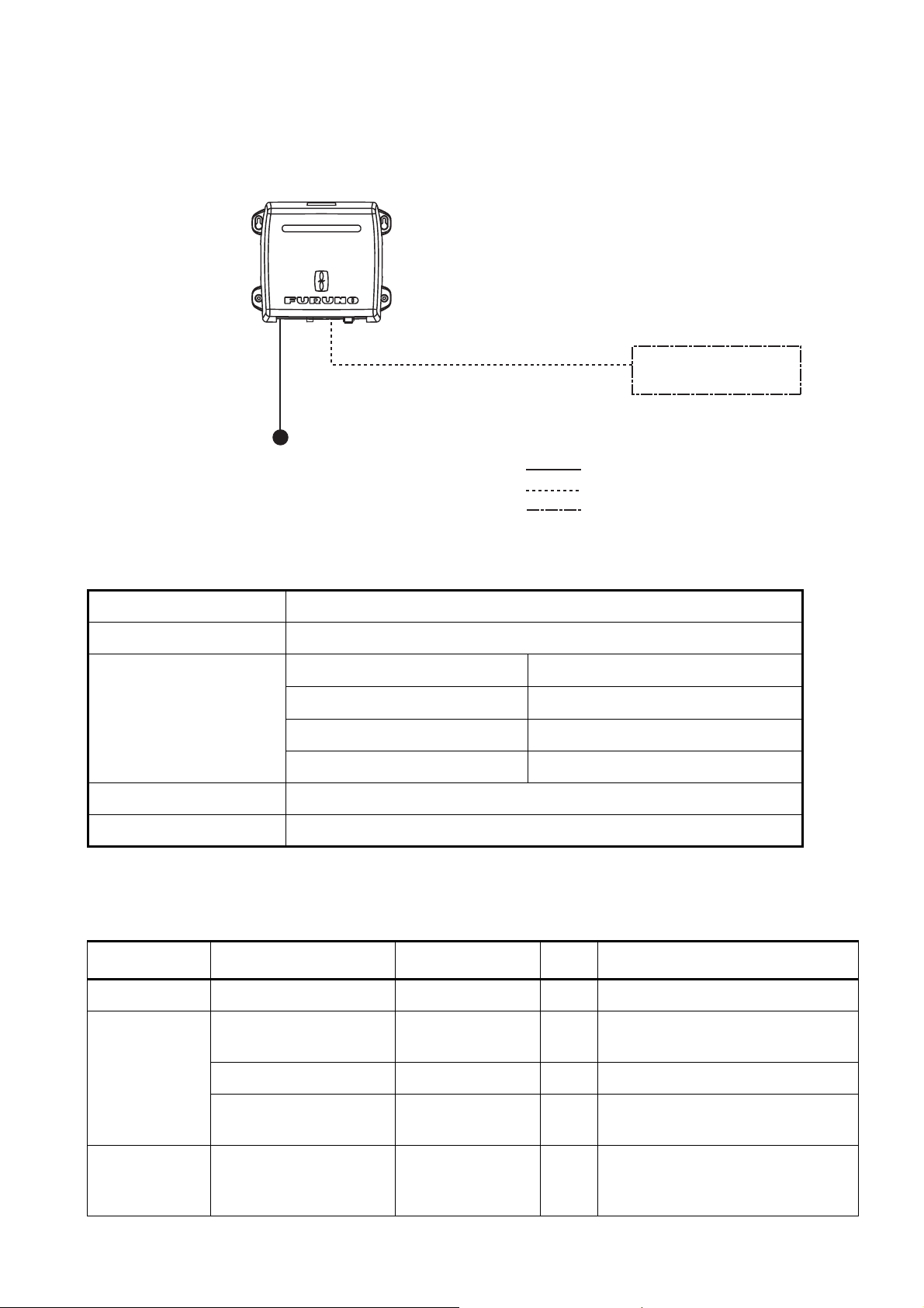
System Configurations
The HUB-101 Ethernet HUB uses an Ethernet interface (100BASE-TX/10BASE-T) to provide the
network communication among the NavNet 3D equipments, and PC. Eight ports are provided on
this HUB. Three HUB-101 can be installed in a LAN series.
Ethernet HUB
HUB-101
MOD-Z072, 2/5/10 m (for NavNet 3D)
VH2P-MVVS0.75X2C
cable
12-24 VDC
MOD-WPAS0001 (for PC)
: Standard supply
: Optional supply
: Local supply
Specifications ETHERNET HUB HUB-101
Transmission speed Half-duplex/Full-duplex: 10 Mbps/100 Mbps
I/O Ports 8 ports
Environmental conditions Ambient temperature
Relative humidity
EMC IEC 60945 Ed.4
Dustproofing, waterproofing IP20 (IEC 60529)
Power supply 12-24 VDC/0.5-0.25 A
-15 to 55
93% (at 40
°C
NavNet 3D Equipment,
PC
x8
°C)
Body color N2.5
Equipment List
Name Type Code No. Qty Remarks
Ethernet HUB HUB-101 - 1
Installation
materials
Spare parts SP19-00901 001-027-240 1 set 1.5A Fuses (2 pcs, Type: FGMB
MOD-Z072-050+ 000-167-176-10 1 LAN cable (for connection with
NavNet 3D equipment)
VH2P-MVVS0.75X2C 000-167--944-10 1 Power cable assy
CP19-01101 001-027-250 1 set Self-tapping screws (Type: 3x20,
Code No.: 000-167-940-10)
125V 1.5A PBF, Code No.: 000157-464-10)
2
Page 3

Installation
Mounting considerations
The HUB-101 can be mounted on a desktop or a bulkhead. When choosing a mounting location
for desktop or bulkhead mounting, keep in mind the following points:
• Locate the unit well away from areas subject to water splash and rain.
• Keep the unit out of direct sunlight because of heat that can build up inside the cabinet.
Mounting
Fix the unit to the mounting location with four self-tapping screws (3x20), referring to the outline
drawing in this manual.
Wiring
Connecting the cable assy (power)
1. Detach the body cover by hands.
2. Loosen four pan head screws (M3x8) and slide the shield cover upward to remove it.
3. Unfasten two pan head screws (M4x12) to remove the cable clamp.
4. Connect the cable assy VH2P-MVVS0.75X2C (supplied) to the power jack in the HUB-101.
Body cover
Shield cover
Pan head screw
(M4x12, 2 pcs.)
Cable clamp
Power jack
Pan head screw
(M3x8, 4 pcs.)
5. Remount the cable clamp, shield cover and body cover in that order.
3
Page 4

Interconnection
To connect the NavNet 3D equipments, use the NavNet 3D optional cables shown below depending on the unit connected.
Connected unit Type Code No. Cable length
NavNet 3D equipment MOD-Z072-020+ 000-167-175-10 2 m
MOD-Z072-050+ 000-167-176-10 5 m
MOD-Z072-100+ 000-167-177-10 10m
PC MOD-WPAS0001-030+ 000-164-609-10 3m
HUB-101
MFD8/12
MFDBB (MPU-001),
PC
RJ45
1
2
3
4
5
6
7
8
MOD-Z072, 2/5/10 m (for Navnet 3D) or
MOD-WPAS0001, 3 m (for PC)
RJ45
P
PP
P
E_TD-P
1
2
E_TD-N
3
E_RD-P
4
SW+
5
SW-
6
E_RD-N
7
NC
8
NC
12-24VDC
SHIELD
GND
x8
VH2P-MVVS0.75X2C, 3.5 m
1
2
3
12-24VDC
DIP switch setting
When multiple MFD8/12/-BBs are connected to the HUB-101 by using MOD-Z072 cables, you can
power all of them by turning on one. The number of DIP switch shows the port number, and turn
on ALL DIP switches used for the ports.
DIP switches
Fuse
1 2 3 4
1 2 3 4
5 6 7 8
5 6 7 8
Note: When connecting with PC(s), use the MOD-WPAS0001-030+ cable and set the applicable
DIP switch(es) to OFF.
ON
OFF
4
Page 5

Turning Power on, LED function
No operation is required for the user. Simply turn on the HUB-101’s DC power source to power it.
LED display
There are LEDs to monitor power and LAN communication on the unit. The LEDs light, blink or go
off according to equipment status as the table shown below. The LEDs show link, mode (full-duplex or half-duplex) and collision statuses. When the equipment is powered, LEDs light as following;
Power on sequence
• Power LED: ON
• LAN LEDs: Blink once, then go off
LED Status Meaning
Power On
Off
.
Power LED
Green
Yellow
LAN LED
Equipment powered
Equipment off
LAN LED (yellow) On
Off
Blinking
LAN LED (green) On
Off
Blinking
Full-duplex
Half-duplex
Data collision
Connected to terminal
Disconnected from terminal
Data TX or RX
5
Page 6

Oct.22'07R.Esumi
 Loading...