


USER MANUAL
Series X - 42.5 inch Multi Vision Display (MVD)
HD 43T22 MVD-MAx-CyTz
Console Mount Model + External Tactile Display Controls (TDC)
where x=ECDIS Factory Calibrated, y=Optical Bonding Technology,
z=Projected Capacitive Touch Screen (Multitouch)
User Manual HD 43 MVD
Updated: 19 Feb 2020 Doc Id: INB101141-3 (Rev 03)
Created: 363 Approved: 6987
Please visit www.hattelandtechnology.com for the latest electronic version of this manual.

Copyright © 2020 Hatteland Technology AS
Eikeskogvegen 52, N-5570 Aksdal, Norway.
All rights are reserved by Hatteland Technology AS. This information may not, in whole or in part, be
copied, photocopied, reproduced, translated or reduced to any electronic medium or machine-
readable form without the prior written consent of Hatteland Technology AS. Review also:
www.hattelandtechnology.com/hubfs/pdf/misc/doc100703-1_permission_to_create_user_manuals.pdf
The products described, or referenced, herein are copyrighted to the respective owners.
The products may not be copied or duplicated in any way. This documentation contains proprietary
information that is not to be disclosed to persons outside the user’s company without prior written consent
of Hatteland Technology AS.
The copyright notice appearing above is included to provide statutory protection in the event of
unauthorized or unintentional public disclosure.
All other product names or trademarks are properties of their respective owners !
WARNING: This is a class A product. In a domestic environment this product may cause radio interference
in which case the user may be required to take adequate measures.
Statement above last revised 31 Jul. 2019

Contents
Contents .......................................................................................... 3
Contents of package ....................................................................................................6
General ............................................................................................ 9
About this manual ......................................................................................................10
About Hatteland Technology ......................................................................................10
www.hattelandtechnology.com ...................................................................................10
Contact Information ....................................................................................................10
Multi Vision Display (MVD) - Introduction ................................................................... 11
Product Labeling ........................................................................................................12
Touch screen products ...............................................................................................14
Installation ..................................................................................... 17
General Installation Recommendations .....................................................................18
First Things First! .......................................................................................................18
Installation and mounting ...........................................................................................18
Installation limitations .................................................................................................20
Ergonomics ................................................................................................................22
Cables ........................................................................................................................23
Maximum Cable Length ......................................................................................... 23
Cable Entries & Connectors (Marked area) ........................................................... 23
General Installation Recommendations .....................................................................24
Conguring DC power input housing connector .........................................................24
Ferrite .........................................................................................................................25
Housing / Terminal Block Connector Overview ..........................................................26
Console Mounting ......................................................................................................28
Physical Connections .................................................................................................30
IND100130-61
3

Contents
Operation ....................................................................................... 33
User Controls .............................................................................................................34
On Screen Display (OSD) Menu Introduction ............................................................36
OSD Key Code (password) overview .........................................................................36
OSD Keycode / OSD Lock Mode ...............................................................................37
OSD “Basic” and “Advanced” Menu modes (examples) ............................................38
OSD Visual User Feedback (examples) ....................................................................39
OSD Menu Structure ..................................................................................................40
Image Settings ....................................................................................................... 40
Color Mode Settings .............................................................................................. 40
PIP Menu ............................................................................................................... 41
OSD Menu ............................................................................................................. 41
Miscellaneous ........................................................................................................ 42
Input Source Settings ............................................................................................. 43
Communication ...................................................................................................... 43
Service Settings ..................................................................................................... 43
Presets ................................................................................................................... 44
Fault Status ............................................................................................................ 44
On Screen Display (OSD) Menu Functions ...............................................................45
Operation Advanced (DDC/CI) ..................................................... 65
Introduction ................................................................................................................66
Specications ............................................................................... 69
Specications - HD 43T22 MVD-MAx-CxTx ..............................................................70
Console/External Remote Model ........................................................................... 70
Technical Drawings ...................................................................... 71
Technical Drawings - HD 43T22 MVD-MAx-CxTx ......................................................72
Console/External Remote Model ........................................................................... 72
Technical Drawings - External Tactile Display Controls (TDC) ...................................73
For Console Mount models .................................................................................... 73
IND100130-61
4

Contents
Technical Drawings - Accessories .............................................. 75
Technical Drawings - IP66 Mount Gasket (EPDM) ....................................................76
P022999 ................................................................................................................. 76
Technical Drawings - HD CMB SX2-G1 .....................................................................77
Console Mount Kit 43 inch ..................................................................................... 77
Technical Drawings - Console Mount Bracket ............................................................78
P006858-1 - Single Bracket ................................................................................... 78
Technical Drawings - HD REM SX1-A1 .....................................................................79
For External Mounting ............................................................................................ 79
Appendixes ................................................................................... 81
Touch Screen Inhibit Functionality .............................................................................82
Preset Signal Timings ................................................................................................83
Pinout Assignments ....................................................................................................84
Basic Trouble-shooting ...............................................................................................87
Declaration of Conformity ...........................................................................................88
Return Of Goods Information .....................................................................................89
General Terms and Conditions ...................................................................................90
Pixel Defect Policy .....................................................................................................91
Notes ..........................................................................................................................92
Revision History .........................................................................................................94
IND100130-61
5

Contents of package
Note: Entries listed below are for Standard factory shipments. Customized factory shipments may deviate from this list.
Item Description Illustration
1 x Power Cable European Type F “Schuko” to IEC. Length 1.8m
TP52/TC01-1,8M
1 x Power Cable US Type B plug to IEC. Length 1.8m
TP11/TC01-1,8M
1 x DP to DP (DisplayPort 1.2) Signal Cable. DP 20P Male. Length 2.0m
VSD101004-1
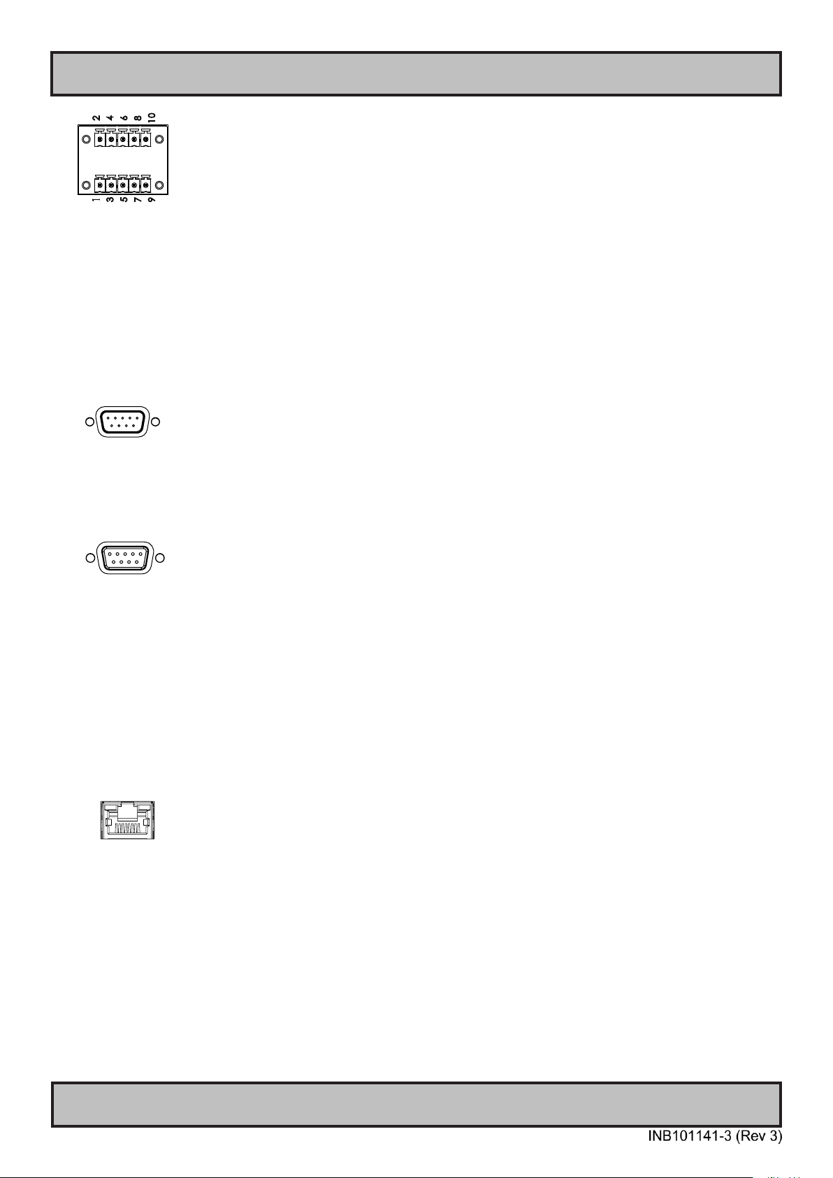
1 x 2-pin DSUB Female DC Power Input internal cable screw terminal
FCE17-E2W2SS-2N0
1 x DSUB Cover for FCE17-E2W2SS-2N0
L17DPPK09JSU
1 x Product Declaration, 1 x Display/MMC Checklist
EUR TYPE F
US TYPE B
IEC
IEC
Test Report Papers
742 711 31
1827732
P022999
HD TDCMVD KIT-A1
1 x Ferrite Würth, Ø Cable: 6.0 - 7.5 mm.
This ferrite is required when connecting a RS-232 cable to the SCOM on the unit
(1 x 9p D-SUB, female, non-isolated) connector to be fully compliant with type approvals.
Review installation chapter for more information.
2 x 5-pin Terminal Block 3.81
for RS-422 / RS-485 / SCOM / Buzzer Module, MC 1,5/ 5-STF-3,81
Refer to “Conguring Housing / Terminal Block Connector” section for usage.
2 x 43” IP66 Console Gasket EPDM Cellular Rubber S-4215, L-Shaped
IP66 Mount Gasket (EPDM), for Flush/Console mount (L-shaped). Both L-shaped gaskets
are mounted on rear of unit as indicated.
1 x Complete Tactile Display Control (TDC) kit
Includes cable VSD203146-1 shown below for connectivity
1 x TDC BOX Extension 15-pin DSUB cable Male to Female for External Tactile Display
Controls (TDC). Length 1.5m. Part of ”HD TDCMVD KIT-A1” above.
VSD203146-1
HD CMB SX2-G1
IND100131-42
1 x 43” EN60945 Console Mounting Bracket Kit
Console Thickness Min: 7.50 [0.30”] - Max: 15.00 [0.59”] mm [inch]
10 x Bracket HD 24T21 SH-A (P025485)
20 x M5x16 Pan Head screw ISO 14583 Torx, A4 (145 050x016 A4T)
20 x M6 C-washers DIN6319 Steel (144 064x120x22)
6

Contents of package
2 x ATEN LockPro HDMI/DP Cablelock
+ 2 x M3x6 Panhead Screw Torx w/sems spring plain 7mm Zc1
Both not factory mounted, delivered loose in package.
2X-EA12
Package may also include: (model dependent)
Item Description Illustration
1 pcs USB Male Cable Type A to Type A. Length 2.0m
If unit was delivered with Factory Mounted Touch Screen option.
VSD100913-1
IND100131-42
7

This page left intentionally blank
8

General
9

Hatteland Technology AS
About this manual
The manual contains electrical, mechanical and input/output signal specications. All specications in this manual,
due to manufacturing, new revisions and approvals, are subject to change without notice. However, the last updated
and revision date of this manual are shown both on the frontpage and also in the “Revision History” chapter. This
user manual is a standard/general manual that applies to all variations of its product family, i.e. deviation from actual
conguration may exist.
About Hatteland Technology
Hatteland Technology is the leading technology provider of specialized display and computer products, delivering high
quality, unique and customized solutions to the international maritime, naval and industrial markets.
The company represents innovation and quality to the system integrators worldwide. Effective quality assurance and
investment in sophisticated in-house manufacturing methods and facilities enable us to deliver Type Approved and Mil
tested products. Our customer-oriented approach, technical knowledge and dedication to R&D, makes us a trusted
and preferred supplier of approved solutions, which are backed up by a strong service network.
www.hattelandtechnology.com
You will nd our website full of useful information to help you make an informed choice as to the right product for your
needs. You will nd detailed product descriptions and specications for the entire range on Displays, Computers and
Panel Computers, Military solutions as well as the range of supporting accessories. The site carries a wealth of
information regarding our product testing and approvals in addition to company contact information for our various
ofces around the world, the global service locations and the technical help desk, all ensuring the best possible
support wherever you, or your vessel, may be in the world.
Contact Information
Sales ofce, Frankfurt / Germany:
Hatteland Technology GmbH
Head ofce, Aksdal / Norway:
Hatteland Technology AS
Eikeskogvegen 52
N-5570 Aksdal, Norway
Switchboard:
Tel: +47 4814 2200
mail@hattelandtechnology.com
Sales ofce, Oslo / Norway:
Hatteland Technology AS
Strandveien 35
N-1366 Lysaker
Norway
Switchboard:
Tel: +47 4814 2200
mail@hattelandtechnology.com
Sales ofce, Vista / USA:
Hatteland Display Inc
450 South Melrose Drive,
Suite #107
Vista, CA 92081
USA
Donna Pallonetti:
Tel: +1 858-282-0659
Fax: +1 858-408-1834
Mehdi Bounoua (Sales Director Europe, Middle East & Africa):
Werner Heisenberg Strasse 12,
D-63263 Neu-Isenburg, Germany
Uwe Scheumann:
Tel: +45 2463 9565
Elke Freisens:
Tel: +49 173 6174753
Goetz Vogelmann: (Sales Director ASIA)
Tel: +49 (0) 6102 37 09 54
Sales ofce, Aix-en-Provence / France:
Hatteland Technology SAS
Actimart- 1140, rue Ampère, CS 80544
13594 Aix-en-Provence, Cedex 3
France
Tel : +33 6 88 33 64 93
For an up-2-date list, please visit https://www.hattelandtechnology.com/contact
General
10
IND100077-1

Multi Vision Displays - Series X
Multi Vision Display (MVD) - Introduction
The Series X Multi Vision Display (MVD) range of products provides
large 4K resolution display solutions to maritime IBS, Automation and
Command Control system integrators. The cutting-edge high definition
LED display technology used, with its high quality brightness and
contrast, enables the presentation of large amounts of data onto one
screen instead of multiple displays.
The 43 inch Series X MVD features 4K screen resolution and
high-end panel technology, it provides unmatched viewing clarity in all
light conditions. Its ultramodern approach represents the pinnacle of
maritime display technology, making it the most advanced platform for
the development of a new generation of sophisticated, function rich
and user-friendly bridge technologies that demand only the best display
solutions to ensure increased navigational safety and efficiency on the
bridge.
Approved for harsh maritime environments where reliability and long life
time are key factors, the new 43 inch Series X MVD display is a robust,
flexible and ergonomic solution, suitable for a wide range of bridge
applications including ECDIS, radar, voyage planning, safety systems
and tactical command & control platforms. Standard features include
console, optical bonding, multi-data input, full dimming, built in OnScreen Display (OSD) and uniquely for a console mounted solution, an
external Tactile button-control panel which can be mounted separately
for operation of the OSD and other parameters. Factory options include
Multi-touch interface and ECDIS Calibrated models.
• 4K UHD - DisplayPort (DP) & HDMI inputs
• LED Backlight Technology
• Full Dimming 100%
• Multi-Touch Option
• Superior Optical Bonding Option
• Resolution at 3840 x 2160 (4K)
• Console mount model
• ECDIS & Radar Compliant
• EN60945 Tested and Type Approved
• Supports Tactor and Active Stylus Pen
IND101057-22
General
11

Product Labeling
Introduction
This section details the locations, content details and specications for factory mounted labels for all currently
available standard Hatteland Technology Maritime Multi Vision (MVD) models. This information will in most cases also
apply for most Customized Models as well, but may differ based on customer requirements, in that case, please refer
to the customized User Manual.
Label Size and Types
ID Label Layout Description Specication
Type : Serial Number Label
Name : Label B
Size : 60mm wide x 20mm high (rectangle size)
Note: Text content of label will match specications
derived from Data Sheet.
Barcode type: CODE128 (used extensively world wide in shipping and packaging
industries. The symbology was formerly dened as ISO/IEC 15417:2007.)
Type : Touch Screen Label
Name : Label B
Size : 60mm wide x 20mm high (rectangle size)
Note: Only present if Touch Screen was part of factory
option order.
Note: Content on label will vary based on Touch Screen type and/or Touch Screen
Controller. Label shown to the right is for illustration purposes only!
Type : Warranty Label
Size : 30mm wide x 23mm high (oval size)
Silver with glue on back, nontearable and made for thermal
transfer printing.
Silver with glue on back, nontearable and made for thermal
transfer printing.
Tamper-proof sticker with glue on
back.
Type : Quality Control (QC) Label
Size : 30mm wide x 23mm high (oval size)
Ordinary sticker with glue on
back.
Warranty Label
If you are to perform service on a unit still under warranty, any warranty will be void if this label show signs of removal
attempts or damaged by screw driver. This label is located on the back of the product and covers a key screw. This is
to aid service departments in determining if there has been any unauthorized service on a unit still under warranty.
Quality Control (QC) Label
This label indicates that the unit is produced, tested and packed according to the manufacture’s QA specications. It
will include a Personal ID and signature by the personnel responsible for approving the unit in production, testing and
warehouse departments.
IND100077-199
12

Product Labeling
Label Locations
Number ID and coloring based on “Label Size and Types“ table from previous page. All illustrations below are seen
from rear (and side where needed) with connectors facing down. Actual labels regarding its size and text orientation
vs product size is drawn in. Due to space restrictions on selected units, some labels will be rotated 90 degrees to t
properly. The arrangement of labels may be shifted/stacked differently as it is based on factory options, such as; Touch
Screen, but they will be grouped together where possible.
Label Positions Notes Applies for Product
Warranty label covers screw.
Labels placed on rear.
- Serial Number Label
- Touch Screen Label (if applicable)
- QC Label
- Warranty Label
HD 43T22 MVD-MAx-CxTx
Console Models
IND100077-199
13

Touch screen products
Introduction to products with touch screen
Nearly all of our products with touch screen use Projected Capacitive Touch screen (PCTS), widely used with great
success on mobile phones and typical pad devices. PCTS can be equally effective also for marine applications.
One of the advantages of PCTS is that it has features seen in both resistive and surface capacitive touch screen
technologies.
Multitouch is dened as the ability to recognize two or more simultaneous touch points. Using projected capacitive
technology allows us to create a more intuitive form of human-device interaction. Touch interface gestures, supported by
projected capacitive sensors, can simplify the interface and provide an intuitive user experience that goes beyond the
typical "button replacement" found in most simple touch interfaces.
Please review the appropriate Product Datasheet (in this manual) to determine if PCTS are supported and/or its
advanced features of additional touch methods (example Tactor and Active Stylus Pen) are available.
The technical benets of PCTS are:
- Very good optical performance (same as surface capacitive)
- Environmentally strong, the touch sensor is inside the product (better than both surface capacitive and resistive)
- Supports Multitouch (Newer Operating System (OS) required in most cases.
- Excellent readability - light transmission of up to 91% through a standard sensor
- Stability - no drift, therefore no recalibration is required
- Pointing device - works with gloved and ungloved finger
- Resistance to contamination - by harsh cleaning fluids and other noxious substances
- Communicates via USB to external computer or internally
Comparisons between general Touch Technologies used by Hatteland Technology:
Technology Optical Performance Gloves Water Durability Multitouch Stylus Objects (Tactor)
Analog Resistive
Surface Capacitive
Projected Capacitive
*Projected Capacitive (PCTS) / Water: Touch Screen Glass Surface can withstand drip and direct rain, but expect reduced capability, detection and
performance if units are exposed to these factors while powered. Hatteland Technology recommends protecting the unit from direct rain or drips if
critical touch operations are to be performed. Take necessary steps (if detected or suspected) within the installation environment to prevent accidental
touch gestures or presses not performed intentionally by a human operator.
-- ++ ++ - - - -++ -- - + - - -++ + + * ++ ++ ++ ++
Touchscreen
IND100110-12
14

Touch screen products
Touch Screen Drivers
All units with Touch Screens are automatically detected by the Operating System via HID. There is no need to install
additional Third-Party touch screen drivers.
Note: By factory default the Default Touch Enabled Source is set to DisplayPort (DP). Touchscreen is not active if
using HDMI. You may change this behaviour in the OSD menu: “Miscellaneous/Touch PWR” as described in the OSD
Menu chapter in this manual.
Microsoft® Windows® 7 / Microsoft® Windows® 10 IoT
- Please use Windows® Generic HID driver, no specic driver needed to use multi-touch.
Microsoft® Windows® XP - For 32, 43 and 55 inch units:
- Multi-Touch Screen is not supported for this Operating System.
- Alternative Single Touch / Mouse Mode not supported.
Ref: OS End-of-Life: https://www.hatteland-display.com/mails/09_2016_eol.html
If you experience any deviation in the touch input accuracy, consider re-calibrating the touch screen for your system.
Please use the standard Operating System functionality to calibrate.
Example for Microsoft® Windows® 10 IoT:
1.Open Control Panel.
2.Click on Hardware and Sound.
3.Under “Tablet PC Settings,” click the Calibrate the screen for pen or touch input link.
4.Under “Display options,” select the display (if applicable).
5.Click the Calibrate button.
6.Select the Touch input option
Example for Microsoft® Windows® 7:
1: Open Control Panel
2: Open “Tablet PC Settings”
3: Under “Display options,” select your display.
4: Click the Calibrate button and follow instructions
5: To save settings, click “Apply” or “OK” on the “Table PC Settings” window.
Linux
- Please use Linux Generic Touch driver. Use kernel 4.10 or later.
Touch screen
IND100110-13
15

This page left intentionally blank
16

Installation
17

General Installation Recommendations
ATTENTION!
IND100148-5 - Rev 05
To prevent damage to
chassis and glass, please
review the illustrations !
Place horizontally on a smooth and clean surface (table with cloth)
Do not stress the corners, nor place it on a coarse and/or dirty surface
CORRECT HANDLING!
WRONG HANDLING!
CORRECT HANDLING!
WRONG HANDLING!
Applies for non-bonded product only: If exposed to humidity
in combination with temperature variations, product might
show condensation on the glass (inside and outside).
Inside condensation can be removed by power on the
product and set brightness to 100%. During minutes the
internal temperature rise will remove condensation.
Humidity Exposure Notice!
Do not stress the corners, nor place it on a coarse and/or dirty surface
WRONG HANDLING!
WRONG HANDLING!
Applies for non-bonded product only: If exposed to humidity
in combination with temperature variations, product might
show condensation on the glass (inside and outside).
Inside condensation can be removed by power on the
product and set brightness to 100%. During minutes the
internal temperature rise will remove condensation.
Humidity Exposure Notice!
First Things First!
Installation and mounting
Note: Each installation case is different, and Hatteland Technology can only offer general tips as each individual case
must be reviewed at local site thoroughly by users themselves and then take necessary steps in basis of the following
points below. It is expected that user has adequate installation knowledge regarding protecting the units in terms of
preventing overheat, provide good air ventilation and be aware of general precautions to ensure long life time of units
and internal electronic components. The points below serve only as a guide and may not all be applicable for the users
installation in every situation.
1. Most of our units are intended for various methods of installation or mounting (panel mounting, bracket
mounting, ceiling/wall, console mounting etc.); for details, please see the relevant mechanical drawings.
2. Adequate ventilation is a necessary prerequisite for the life of the unit. The air inlet and outlet openings must
denitely be kept clear; coverings which restrict ventilation are not permissible.
IND100078-64
Installation
18

General Installation Recommendations
Table/Panel
3. The 43 inch units in particular are tested and approved for horizontal mount and vertical mount.
Please consider the thermal situation when mounting the unit, in particular when mounted at (horizontally).
"Air traps" must be avoided, active ventilation might be required, depending on the actual installation.
Console Flat Mount - Thermal Solution
LCD Panel
Hot air needs to escape/circulate the console casing.
Thermally controlled fans are suggested as the optimal solution.
Please note recommended mounting for Non-Bonded units vs Bonded units and requirements.
Based on a permanent mounting. Take notice of orientation of Front Glass below:
With or without Bonding OK
With or without Bonding OK
0°
0°
45°
Bonding Required!
90°
4. To further improve the thermal situation, we recommend using forced air passing by the product. In some cases,
convection based cooling can create “heat zones” around the product. This may be required in high temperature
applications and also when there is reason to expect temperature problems due to non-optimal way of mounting.
5. Exposure to extreme direct sunlight can cause a considerable increase in the temperature of the unit, and might
under certain circumstances lead to excessive temperature. This point should already be taken into consideration
when the bridge equipment is being planned (sun shades, distance from the windows, ventilation, etc.)
6. Space necessary for ventilation, for cable inlets, for the operating procedures and for maintenance, must be
provided.
90°
45°
7. If the push buttons of the product are not illuminated, an external, dimmable illumination (IEC 60945 Ed. 4, 4.2.2.3,
e.g. Goose neck light) is required for navigational use. The illumination should be free from glare and adjustable to
extinction.
8. Information about necessary pull-relievers for cables is indicated in the Physical Connection section of this manual.
Attention must be paid to this information so that cable breaks will not occur, e.g. during service work.
9. Do not paint the product. The surface treatment inuences the excess heat transfer. Painting, labels or other
surface treatments that differ from the factory default, might cause overheating.
10. Exposure to heavy vibration and acoustic noise might under certain circumstances affect functionality and expected
lifetime. This must be considered during system assembly and installation. Mounting position must be carefully
selected to avoid any exposure of amplied vibration.
Installation
IND100078-64
19

General Installation Recommendations
Installation limitations
Due to environmental factors, please review the section below.
Projected Capacitive Technology (PCTouch) MULTITOUCH and in general Touch Screen glass:
For all units with a factory mounted touch screen (and for outdoor use) the touch controller can react and is
sensitive to raindrops. The only solution to this situation is not to mount the unit in a vertical angle lower
than ±30 degrees, i.e. at mounting. This is to ensure that the touch screen is not activated by staying/running
raindrops and accidentally automatically chooses functions in your running chart, radar or other software
installed.
IND100078-64
Installation
20

General Installation Recommendations
General mounting instructions
1. The useful life of the components of all Electronics Units generally decreases with increasing ambient temperature;
it is therefore advisable to install such units in air-conditioned rooms. If there are no such facilities these rooms
must at least be dry, adequately ventilated and kept at a suitable temperature in order to prevent the formation of
condensation inside the display unit.
2. With most Electronic Units, cooling takes place via the surface of the casing. The cooling must not be impaired by
partial covering of the unit or by installation of the unit in a conned cabinet.
3. In the area of the wheel house, the distance of each electronics unit from the magnetic standard compass or the
magnetic steering compass must not be less than the permitted magnetic protection distance. This distance is
measured from the center of the magnetic system of the compass to the nearest point on the corresponding unit
concerned.
4. Units which are to be used on the bridge wing must be installed inside the “wing control console” protected against
the weather. In order to avoid misting of the viewing screen, a 25 ... 50 W console-heating (power depending on the
volume) is recommended.
5. When selecting the site of a display unit, the maximum cable lengths must be considered.
6. When a product is being installed, the surface base or bulkhead must be checked to ensure that it is at in order to
avoid twisting of the unit when the xing screws are tightened, because such twisting would impair mechanical
functions. Any unevenness should be compensated for by means of spacing-washers.
7. Products with AC input must be grounded to protective Earth (Safety Ground) when necessary via the bolt (usually
on terminal plate) available on the product.
Products with DC input must be grounded to protective Earth (Safety Ground) via the bolt (usually on terminal
plate) available on the product.
A shorter and thicker cable gives better grounding. A 6mm² is recommended, but a 4mm² or even 2.5mm² can be
used for this purpose.
8. Transportation damage, even if apparently insignicant at rst glance, must immediately be examined and be
reported to the freight carrier. The moment of setting-to-work of the equipment is too late, not only for reporting the
damage but also for the supply of replacements.
9. The classication is only valid for approved mounting brackets provided by Hatteland Technology. The unit should be
mounted stand-alone without any devices or loose parts placed at or nearby the unit. Any other type of mounting
might require test and re-classication.
IND100078-64
Installation
21

General Installation Recommendations
Ergonomics
1. The front surface of the display glass has an anti-reective (AR) coating which can be scratched and damaged with
improper cleaning. It is recommended using only 90+% pure Isopropyl alcohol (Isopropanol) and a soft fabric
cloth for this rst cleaning. Fold a cloth into a small pad, dampen the cloth with alcohol, and wipe the glass from
one edge to the other in one direction with one continuous motion. The product glass will require cleaning as
needed. The soft cloth & alcohol wipe is recommended to clean ngerprints and oils off the glass. Water stains
(including coffee, tea & soda) should be rst cleaned off the glass with a soft fabric cloth wet with water,
immediately followed with wiping using an alcohol wetted cloth.
2. Adjust the unit height so that the top of the screen is at or below eye level. Your eyes should look slightly
downwards when viewing the middle of the screen.
3. Adjust screen inclination to allow the angle of gaze to remain at the center of the screen approximately
perpendicular to the line of gaze.
4. When products are to be operated both from a sitting position and from a standing position, a screen inclination of
about 30° to 40° (from a vertical plane) has turned out to be favorable.
5. The brightness of displays is limited. Sunlight passing directly through the bridge windows - or its reection - which
falls upon the screen workplaces must be reduced by suitable means (negatively inclined window surfaces,
venetian blinds, distance from the windows, dark coloring of the deckhead).
6. The use of ordinary commercial lter plates or lter lms is not permitted for items of equipment that require
approval (by optical effects, “aids” of that kind can suppress small radar targets, for example).
7. For ECDIS applications, the minimum recommended viewing distance are as follows:
(IEC62288, Part 7.5 Screen resolution)
43 inch = 842mm
IND100078-64
Installation
22

General Installation Recommendations
Cables
Use only high quality shielded signal cables.
Maximum Cable Length
Any cable should generally be kept as short as possible to provide a high quality input/output. The maximum signal
cable length will depend not only on the signal resolution and frequency, but also on the quality of the signal output from
the computer/radar. For optimal signal quality, use HDMI 1.4/2.0 compliant cables.
Cable Entries & Connectors (Marked area)
Illustration below for smallest/largest sizes only.
Back View - Console Models
IND100078-64
Installation
23

General Installation Recommendations
Conguring DC power input housing connector
Note: Only applicable for DC models!
For installations that require DC power input, use the provided
2-pin DC Power Input housing with internal cable screw terminal.
It is recommended that thickness of cables are
Minimum 20 AWG and Maximum 18 AWG. Length should be
determined by qualied personnel.
1: Open the housing
2: Unmount the fasteners. (FIG 1)
3: Mount power cables to screw terminal (FIG 2). Note polarity!
4: Secure the cable tightly with fasteners (FIG 3, FIG 1)
5: Close the housing
-
FIG 3
+ -
DC shall be grounded to protective Earth / Safety Ground!
Review “General Mounting Instructions” in the “Installation” chapter earlier in this manual.
+
FIG 1
FIG 2
Screw terminal
+ -
IND100078-37
Installation
24

General Installation Recommendations
Ferrite
The ferrite prevents high frequency electrical noise (radio frequency interference) from exiting or entering the
equipment. This ferrite is required when connecting a RS-232 cable to the SCOM on the unit
(1 x 9p D-SUB, female, non-isolated) connector to be fully compliant with type approvals.
The ferrite should be mounted (clipped in place on the cable) and
located as close as possible to the connector piece that connects to
the rear of computer.
When ready: Open the ferrite, place the cable inside as shown in
FIG1, and then gently close it until a click can be heard (FIG2). You
may close and re-open them as many times as required during the
installation.
FIG1
FIG2
To computer
Red Line indicate where Ferrite should be mounted (as close as possible to the connector).
Do not mount ferrite (Orange square) below the red line!
Typenumber Ferrite Type Dimetric View Preferred distance of ferrite. Side view.
HD 43T22 MVD-MAx-CxTx
Console Models
1 x 742 711 31
Würth type
To computer
IND100210-40
Installation
25

General Installation Recommendations
Housing / Terminal Block Connector Overview
Housing / Terminal Block connectors are available which plug into the connector area of the unit. They are mounted
by factory default and delivered with the unit. The housing / terminal block connectors have steering rails, which
ensures that it cannot be mounted wrong. The color of these connectors may vary between black, green and orange
depending on manufacturer. You may use approved equivalents of these connectors, but note that the the warranty
will be void if any damage would occur to either the unit’s original PCB terminal socket connector or inside the unit
(electronic components, boards etc.).
Illustration Pins Manufacturer Details Connector used for module
5-pin MC 1,5/ 5-STF-3,81
Screwdriver: SZS 0,4X2,5mm
VDE, slot-headed.
Tightening torque min. 0.22 Nm.
Tightening torque max 0.25 Nm.
If your installation requires additional cable fasteners support, please visit and purchase directly from manufacturer:
Illustrations below are approximate, actual Housing and Hood may deviate slightly, but function remains the same.
Cable Housing - Illustration Cover Hood - Illustration
KGG-MC 1,5/ 5 (5-pin)
For 5-pin:
https://www.phoenixcontact.com/online/portal/us?uri=pxc-oc-itemdetail:pid=1834372&library=usen&pcck=P-11-02-01&tab=1
For 5-pin
http://catalog.weidmueller.com/procat/Product.jsp;jsessionid=D399022A1B3211C0146BCBE716D93211?productId=(%5b1005300000%5d)
• RS-422 / RS-485 / SCOM (Serial Remote Control) / Buzzer
Identi ed on Hatteland Technology product datasheet as:
“Terminal Block 3.81”
BCZ 3.81 AH05 BK BX (5-pin)
IND100210-31
Installation
26

General Installation Recommendations
Conguring Housing / Terminal Block connectors
Below is a brief illustration that might be useful during conguration and installation of such connectors. You will need
suitable pre-congured cable(s) and tools to congure the connector(s) and cable(s) that are present in your
installation environment. Below is an example procedure for a 2-pin DC power connector. The procedure is the same
for other connectors of this type as listed in table on previous page. Unit and connector used as illustration below is
for reference only.
FIG 3
FIG 1
FIG 2
FIG 4
- +
FIG 1: Unscrew (from top) or make sure that the screw terminal (square area) is fully open, so you can secure the
inserted cables correctly to the loose housing connector (it may already be plugged into the unit as per factory
installation).
FIG 2: Insert cables* (from front) and screw / secure the cables by turning the screw on top of the housing to secure
the cables properly. Check that the cables are rmly in place and do not appear loose or fall out when pulling gently.
*Note: Required polarization verication (for instance -/+ for DC power input) should conform with the markings on
the connector area of the unit. Ignoring the markings on the unit or its add-on modules might damage the unit and/or
external equipment in which end, warranty will be void.
FIG 3: Plug the housing into the appropriate connector area of the unit (glass should be facing down) and check again
that the cables secured conform with the markings on the connector area of the unit. Finalize the installation by
fastening the screws located in front on each side of the housing connector (FIG 4).
- +
- +
- +
Connector / Function Recommended Cable Thickness
2-pin DC Power Input (Terminal Block 5.08) Minimum 20 AWG - Maximum 18 AWG
4-pin CAN (Terminal Block 3.81) Minimum 22 AWG - Maximum 20 AWG
5-pin NMEA COM (Terminal Block 3.81) Minimum 22 AWG - Maximum 18 AWG
5-pin DIO (Terminal Block 3.81) Minimum 22 AWG - Maximum 18 AWG
Installation
27
IND100210-31

Installation Procedures
Console Mounting
The Console Mount Display model comes with a complete mounting bracket system and the External Remote Control
(Tactile Display Controls (TDC)) as standard (HD TDCMVD KIT-A1). You need: Torx T25 tool,
1 pcs of HD CMB SX2-G1 kit (included in delivery).
Console Thickness Min: 7.50 [0.30”] - Max: 15.00 [0.59”] mm [inch]
Attention: A suitable pre-cut panel cutout should be made prior to mounting. Do not force the unit into the panel
cutout as it might break the outer glass or scratch the chassis on the unit. Make sure that the panel cutout is not too
tight for the unit. Please disconnect ALL cables before proceeding. Please re-check the relevant and required panel
cutout measurements if unsure.
Item Amount Art Description Notes
10 P006858-1 Console Mounting Bracket for Slim Units
20 145 050x016 A4T M5x16 Pan Head screw ISO 14583 Torx, A4 For P006858-1
20 144 064x120x22 M6 C-washers DIN6319 Steel For P006858-1
▼ 1: Slide the unit into the panel cutout carefully. User
Controls and Connector Area should be facing downwards.
▼ 3: Secure each bracket with the provided screws as
illustrated below. Make sure you do it equally and even for all
4 sides. Use Torque Force 3.75Nm. Note the orientation of
brackets before you begin.
Bracket
Washer
Screw
▼ 2: Mount all 10 brackets in rear as indicated.
Closeup Bracket
▼ 4: Review closeup of the mounting of brackets
with screws. Seen from bottom side.
Display
Console
IND100078-65
Installation
Bracket+Washer+Screw
28

Installation Procedures
232.00
9.13
37.00
1.46
R2.00
▼ 5: Mount the External Tactile Display Controls (TDC) unit as desired elsewhere in the console (Note: Cable
length from factory is 1.5m). Review Technical Drawings in this user manual for more details or see Panel Cutout
reference below. Connection between TDC and Display must occur inside console.
0.08
Note: Cable that connects the TDC unit to the Display unit must under no circumstances be connected or
disconnected while the Display unit is powered on. Failure to do so may result in a damaged TDC or Display Unit
IND100078-65
Installation
29

Physical Connections
Connection area
Power Input AC USB Touch+SCOM2 x HDMI1.4 InDisplayPort (DP) In
Firmware Update SCOM RS-422/RS-485User Port
Grounding Screw TDC InterfacePower Input DC SCOM RS-232SCOM RJ45 Network
1 x HDMI2.0 In
POWER INPUT AC:
The internal AC power module supports 100-240V AC 50/60Hz power input.
Connect your DC power cable to the 2P Amphenol FCC17 D-SUB Connector (male). Secure the cable to the hex
spacers provided on the unit, and secure the other end to your power supply. The internal DC power module supports
24VDC. Please check specifications for your unit.
+ -
POWER INPUT DC:
Multi-power note:
The unit has a dual input power supply which will accept both AC and DC input. If both inputs are connected, the
unit will be powered by AC. If AC is disconnected it will automatically switch over to DC without affecting the operation
of the unit. This makes it possible to use AC power as primary power and a 24V battery as secondary power,
eliminating the need for expensive UPS systems.
IND100133-71
30
Physical Connections
RS-422 / RS-485 COM I/O:
The COM (non-isolated RS-422/485) allows functionality to communicate with serial based equipment including
external buzzer functionality. Connect and fasten your cables from your compatible external equipment to the 5-pin
Terminal Block 3.81 connector. Please review the “Pinout Assignments” chapter as well as “Housing / Terminal Block
Connector Overview” in this manual for more information. One example of peripherals from Hatteland Technology is
the External Remote Controller (HD REM SX1-A1). This connector will allow remote control of the display unit to
control common functions like brightness, input source and more via the Serial Remote Control (SCOM) as provided
by Hatteland Technology.
Hatteland Technology’s Serial Remote Control Interface (SCOM) protocol document can be downloaded from:
https://www.hattelandtechnology.com/hubfs/pdfget/inb100018-6.htm
USER PORT (Potentiometer I/O):
Allows for controlling Brightness of the displayed image on screen by connecting an external remote control to the
D-SUB 9P connector (male) which has Potentiometer Analog Input, User Brightness (BRT), I2C and +5VDC & 12VDC
OUT functionality built in. Review the “Pin Assignments” chapter in this manual for more information on how to
activate this functionality. Note: Do not connect/disconnect cables to this connector while product is powered on.
RS-232 SCOM I/O:
This D-SUB 9P connector (female) provides additional functionality for the unit. The Serial Remote Control (SCOM)
features a RS-232 (non-isolated) interface for controlling internal parameters like brightness. You can access most of
the parameters available in the OSD menu and with special commands control the unit externally. This COM can also
be used to upgrade the rmware for the graphic controller inside the unit which is available on request and through
service channels (for qualied personnel only). Fasten your external cable to the connector using the provided screws
on the cable housing.
Please review “Management Settings/Communication” in the “OSD Menu Functions” chapter for more information.
Hatteland Technology’s Serial Remote Control Interface (SCOM) protocol document can be downloaded from:
https://www.hattelandtechnology.com/hubfs/pdfget/inb100018-6.htm
SCOM Network/LAN I/O:
Supports 10/100/1000Mbps Ethernet (LAN). Suitable for twisted pair cables CAT.5E. Make sure the network cable
connector ”clicks” into the RJ-45 connector. This connector will allow remote control of the display unit to control
common functions like brightness, input source and more via the Serial Remote Control (SCOM) as provided by
Hatteland Technology.
Hatteland Technology’s Serial Remote Control Interface (SCOM) protocol document can be downloaded from:
https://www.hattelandtechnology.com/hubfs/pdfget/inb100018-6.htm
IND100133-71
31

Physical Connections
USB TOUCH SCREEN + SCOM:
Connect a TYPE A USB Cable between this connector and your PC. Port is USB2.0 (<5m). This connector will
allow Touchscreen connectivity and/or remote control of the display unit to control common functions like brightness,
input source and more via the Serial Remote Control (SCOM) as provided by Hatteland Technology.
Hatteland Technology’s Serial Remote Control Interface (SCOM) protocol document can be downloaded from:
https://www.hattelandtechnology.com/hubfs/pdfget/inb100018-6.htm
GROUNDING SCREW:
Please review “General mounting instructions” in the “Installation” chapter, pt. 7 for more information.
Interface Connector (External Tactile Display Controls - TDC):
This 15P DSUB (male) connector provides an interface for User Controls in order to Power On/OFF the unit as well as
full access to the OSD Menu, Brightness, Contrast functions and more. On certain models this connector is already by
factory default occupied and connected.
Secure the Interface cable to the hex spacers provided on the unit and make sure you do not bend any of the pins
inside the connector when connecting.
Note: Cable that connects the TDC unit to the Display unit must under no circumstances be connected or
disconnected while the Display unit is powered on. Failure to do so may result in a damaged TDC or Display Unit
DisplayPort (DP) IN:
Connect your DP (male) cable rmly into to the DisplayPort (v1.2) 20P connector (female) of the unit. For additional
secure mounting, consider using the provided “ATEN LockPro HDMI/DP Cablelock”. For optimal signal quality and
stability, use HDMI 1.4/2.0 compliant cable.
HDMI IN #1, #2, #3:
Connect your HDMI (male) cable rmly into to the HDMI 19P connector (female) of the unit. HDMI1 = 2.0, HDMI2 and
HDMI3 = 1.4. For additional secure mounting, consider using the provided “ATEN LockPro HDMI/DP Cablelock”. For
optimal signal quality and stability, use HDMI 1.4/2.0 compliant cable.
FW (Firmware) Update:
Intended for on-site possibility to upgrade/service the internal Firmware inside the unit that could x issues or to
improve functions for either Video Controller or Glass Display Control™ (GDC). Upgrading should only be performed
by a skilled technician familiar with typical Firmware/Bios upgrading. Insert a TYPE A USB Memory Stick into this
connector. Port is USB2.0 (<5m).
Firmware Upgrade Procedure available on request, reference: DOC206316-1.
In case of problems during Firmware update, please visit our support webpage:
https://www.hattelandtechnology.com/support/contact
32
IND100133-71

Operation
33

User Controls
USER CONTROLS OVERVIEW
The Tactile Display Controls (TDC) External Remote allows interactivity and feedback. In addition, all buttons and
symbols are backlight illuminated. Note that these symbols are only illuminated when suitable power is connected.
Back / Key1 Forward / Key2
Buzzer
Power ON:
To turn the unit on, verify that the “Power LED” symbol is illuminated in orange (indicates suitable power is connected)
and press the button and hold until the symbol changes to green light or an image appears on the screen.
Power OFF:
To turn the unit off, press the power button and hold until the “Power LED” either illuminates/changes from green to
orange or the image on screen disappears.
Navigation / Hot Keys
OSD Menu
Service Indicator
ECDIS Status / Indicator
Brightness &
Decrease/Increase
Power On/Off
Light Sensor
Power LED
OSD Menu, Navigation:
MENU: To access the main OSD menu, press the “MENU” button and the OSD menu will clearly be seen as an
overlay over the existing displayed image. The complete denition of all the menus and functions are available in the
“OSD MENU FUNCTIONS” chapter in this manual.
Navigation: If the OSD (On Screen Display) menu was activated (and is clearly visible on screen), both the “<” and
“>” buttons are used to navigate and set options within the OSD menu. If OSD menu is not active on screen (and not
assigned to any Hot Key functions) these buttons are not illuminated or active.
Hot Keys (Key1 / Key2): Additionally you can assign the (<) and (>) to behave like “Hot Keys”. Please note that only
assigned functions to the Hot Keys will make them illuminate and become active even if the OSD Menu was not
shown on screen. If Hot Keys were dened and by pressing MENU, the (<) and (>) will revert back to Navigation logic,
and any Hot Keys functions will have to be disabled in order to navigate the menu properly at this point.
Review “Miscellaneous > Key1/Key2” in OSD Menu for more information
Operation
IND100064-46
34

User Controls
Service Indicator:
Reserved for future use, no built-in function dened.
Brightness Adjust:
Brilliance / Brightness adjustment of the displayed image is adjusted by pressing the (-) or (+) buttons.
ECDIS Status / Indicator: (optional factory standard)
For units that have been factory ECDIS calibrated this symbol will illuminate in green constantly as long as the unit is
powered. The symbol will illuminate in orange when the Brightness/Brilliance is adjusted either above or below ECDIS
factory calibration point.
To be able to stay within ECDIS calibrated range, please assure that this symbol are not illuminated in orange color
during operation. Note that by touching this symbol no action will be performed or has been assigned.
Light Sensor:
Used to sense level of ambient light in the surrounding environment. The sensor data can be read by suitable software
through the Hatteland Technology SCOM functionality of the unit and thus can be used to control brightness remotely.
Note: This sensor is barely visible to the eye and lies under the glass. It has no illumination behind to indicate its
position. Touching or covering this area will naturally make the sensor data inaccurate and should be avoided!
By standard Hatteland Technology factory defaults this function has not been pre-dened.
Please review “SCOM Section: Glass Display Control™ (GDC)” section and the ““LIS” - Read Ambient Light Sensor”
command for more information in the Serial Remote Control Interface (SCOM) protocol document, located at:
http://www.hattelandtechnology.com/hubfs/pdfget/inb100018-6.htm
Note:
In the following “On Screen Display (OSD)” menu chapter, these buttons are referenced as:
“MENU”
“(-) Brilliance/Brill (+)”
“(<) Navigation (>)”
These can also be dened as “Hot Keys”.
Review “Miscellaneous > Key1/Key2” in OSD Menu
Buzzer:
Only functional for units ordered with Buzzer functionality. Frequency range is 1500-2500Hz. The location of the
buzzer hole (physical hole in glass) is barely visible to the eye. Touching this area will naturally mute buzzer sound or
in some cases make it lower or change audible frequency. In no circumstances should this area be blocked by either
stickers or objects! Please review the “Pinout Assignments” chapter in this manual for controlling the Buzzer
functionality and review the Serial Remote Control Interface (SCOM) protocol document, located at:
http://www.hattelandtechnology.com/hubfs/pdfget/inb100018-6.htm
IND100064-46
Operation
35

OSD Menu Overview
On Screen Display (OSD) Menu Introduction
The OSD menu consists of single menu overlay with two columns which are Sub-Menu and Adjust Value / Choices
Menu which are easy to navigate through. All functions are explained in-depth later in this user manual. Prior to using
the OSD menu, you should be sure to familiarize yourself with how to physically access the menu, how to navigate
up/down/left/right, how to modify values, exiting menus and more. The OSD Menu overlay will appear over any signal
input and based on OSD settings either be position in center, become transparent depending on
factory default setting or by user’s own preference.
Please note: Factory default illustrations only! Available functions, icons and text may deviate slightly from actual OSD menu on
your product due to different OSD software congurations and customized solutions.
OSD Key Code (password) overview
During use/accessing the OSD menu, based on factory default or customized conguration, there might be a pop-up
requester asking for a Key Code (password) to gain further access to requested menu. These are 3 digits long.
Keycode Description
321 Applies for “ECDIS Compliance” products. Code must be entered to get access to OSD MENU.
Congured in OSD parameter: “OSD Menu > OSD Lock Mode > Menu Protect”
362 If OSD are in Basic Mode, entering code gets access to Advanced Mode.
Congured in OSD parameter: “OSD Menu > OSD Mode > Advanced”
--- Service Mode - Only applicable for authorized service personnel.
Congured in OSD parameter: “OSD Menu > OSD Mode > Service”
User Controls
IND100064-65
36

OSD Menu Overview
OSD Keycode / OSD Lock Mode
During use, a small requester may pop-up on screen asking you for a “Key Code”. This is a safety feature (due to
ECDIS Compliance) that might be predened in your setup. To quickly understand how to enter a code, navigate and
nally access the underlying main menu, simply follow the illustration below. The “Key Code” is by factory default
“321”. If the “Key Code” requester do not appear on screen, you can skip reading this section for now and proceed to
the next page.
Advanced
0 0 0
Active Display Area + Requester
1: Typical position of requester on screen.
Advanced
3 2 1
Close-up of Requester
4: Repeat step 2 and 3, until
“Key Code” reads “3 2 1” and nally touch
menu button to continue.
Advanced
0 0 0
Close-up of Requester
2: Enter rst number (from 0 to 9).
Use “Navigation/Hot Keys” touch buttons to
increase/decrease. Number change in real time.
Active Display Area + OSD Menu
5: The OSD menu appear
Advanced
3 2 0
Close-up of Requester
3: Now touch menu button to store rst
number and proceed to second number.
Current number will appear in red color
After the code is successfully entered you will gain access to the OSD Menu and a multitude of functions will be
available for adjusting or reviewing. Please proceed to the next page, where you will learn the differences between
“Basic” and “Advanced” menu modes and a complete map of all the underlying functions available within.
User Controls
IND100064-65
37

OSD Menu Overview
OSD “Basic” and “Advanced” Menu modes (examples)
You may encounter two different menu size setups based on factory default or by customized preset conguration.
The “Basic” Menu mode offers easy and clear access to most commonly used functions. The “Advanced” Menu mode
offers more choices with technical information and is suited for technical minded users or specic conguration needs.
Example of BASIC MENU
DisplayPort Resolution: 3840x2160@60Hz
Image Settings Select source to Adjust Main Input
Color Mode Settings Brightness 128
PIP Menu Contrast 128
OSD Menu Saturation 128
Miscellaneous Hue 128
Input Source Settings Sharpness 128
Communication Analog VGA Adjustment
Service Settings Auto Adjustment On
Presets Exit
Fault Status
Exit
Main Input:
Third Input:
Second Input:
Fourth Input:
Basic OSD Menu showing for example “Image Settings” chosen in the menu. The rst column is visible at all times, while the two next columns
will change based on contents of that submenu and adjustable values. The design and size of OSD menu area does not change in any setting.
In Basic Mode, certain settings have been locked (gray text) to allow only the most common basic functions available for user only.
Example of ADVANCED MENU
DisplayPort Resolution: 3840x2160@60Hz
Image Settings Select source to Adjust Main Input
Color Mode Settings Brightness 128
PIP Menu Contrast 128
OSD Menu Saturation 128
Miscellaneous Hue 128
Input Source Settings Sharpness 128
Communication Analog VGA Adjustment
Service Settings Auto Adjustment On
Presets Exit
Fault Status
Exit
Main Input:
Third Input:
Second Input:
Fourth Input:
Advanced OSD Menu showing for example “Image Settings” chosen in the menu. The rst column is visible at all times, while the two next
columns will change based on contents of that submenu and adjustable values. The design and size of OSD menu area does not change in any
setting. In Advanced Mode, all settings are available (except those which are dependent on signal inputs or by product design).
User Controls
38
IND100064-65

OSD Menu Overview
OSD Visual User Feedback (examples)
Throughout all OSD menus there are certain graphic elements you need to familiarize yourself with. These are to
visually indicate that a value can be increased/decreased, accessed, display a Slide Bar Meter or just for information
purposes only. All functions have text based, human readable text for clarity and uses no graphical icons. A Slider Bar
with number beside it will indicate the value has a minimum, current and max limit. All changes in values and lists
happen in real time as you touch the menu button and/or touch navigation buttons.
Image Settings PIP H. Position
A round frame with text marked in red, means this is the currently
selected item in the menu with additional settings that can be adjusted
RS232 128
A dot next to an item in the menu, means that this function is currently
active and set by user previously (stored setting).
Note: The examples above are the most common ones displayed.
Text marked in gray color means that the current function in menu is
either not enabled or is not available to adjust.
A Slider Bar meter indicates the minimum and maximum value for the
current function selected. The current value is written to the left.
User Controls
IND100064-65
39

OSD Menu Overview
OSD Menu Structure
In this table all functions within menus and their submenus with choices are shown. Functions with a “>” in the end,
indicates a submenu or list of options will be displayed.
Image Settings
Main Menu Sub Menu Adjust / Choices Menu
Image Settings > Select Source to Adjust > - Main Input
Brightness > (Slider Bar)
Contrast > (Slider Bar)
Saturation > (Slider Bar)
Hue > (Slider Bar)
Sharpness > (Slider Bar)
Analog VGA Adjustment > Command not in use/No Function
Auto Adjustment > Command not in use/No Function
< Exit
- Second Input
- Third Input
- Fourth Input
Color Mode Settings
Main Menu Sub Menu Adjust / Choices Menu
Color Mode Settings > Color Temperature > - 9300K
Gamma > - No Calibration
Red Gain > (Slider Bar)
Green Gain > (Slider Bar)
Blue Gain > (Slider Bar)
Gamma Reset > - On
< Exit
- 8000K
- 6500K
- User
- Calibration DisplayPort
- Calibration HDMI
- Off
User Controls
IND100064-65
40

OSD Menu Overview
PIP Menu
Main Menu Sub Menu Adjust / Choices Menu
PIP Menu > PIP Mode > - PIP Off
PIP Child Size > (Slider Bar)
PIP H. Position (Slider Bar)
PIP V. Position (Slider Bar)
Swap Source (Automatic Action)
< Exit
OSD Menu
Main Menu Sub Menu Adjust / Choices Menu
OSD Menu > OSD Language > - English
OSD H. Position > (Slider Bar)
OSD V. Position > (Slider Bar)
OSD Timeout (sec) > (Slider Bar)
OSD Transparent > (Slider Bar)
OSD Mode > - Basic
OSD Lock Mode > - Normal
OSD Key Outdoor > - On
< Exit
- PIP Child
- PIP Split
- PIP Wide
- Triple PIP
- Quad PIP
- Français > (French)
- Deutsch > (German)
- Italiano > (Italian)
- Norsk > (Norwegian)
- 日本語 > (Japanese)
- 簡體中文 > (Simplied Chinese)
- Advanced
- Service
- Menu Protect
- Full Protect
- Off
User Controls
IND100064-65
41

OSD Menu Overview
Miscellaneous
Main Menu Sub Menu Adjust / Choices Menu
Miscellaneous > Aspect Ratio > - Full
GDC Sensitivity > (Slider Bar)
Power Plan > - Enable
LAN/Sleep-Mode > - Enable
Touch PWR > - DP
Power Button > - Enable
DDC/CI > - DP
Key 1 > - Black Level
Key 2 > - Black Level
< Exit
- 16:9
- 4:3
- 1:1
- Native
- Disable
- Disable
- HDMI1
- HDMI2
- HDMI3
- Signal
- Active
- Off
- Disable
- HDMI1
- HDMI2
- HDMI3
- Disable
- Signal
- Active
- Touch PWR
- Main Input
- Second Input
- PIP Mode
- Aspect Ratio
- Swap Source
- Test Pattern
- Language
- No Function
- Touch PWR
- Main Input
- Second Input
- PIP Mode
- Aspect Ratio
- Swap Source
- Test Pattern
- Language
- No Function
User Controls
IND100064-65
42

OSD Menu Overview
Input Source Settings
Main Menu Sub Menu Adjust / Choices Menu
Input Source Settings > Main Input > - Display Port
Second Input > - Display Port
Third Input > - Display Port
Fourth Input > - Display Port
Auto Source > - On
< Exit
- HDMI1
- HDMI2
- HDMI3
- HDMI1
- HDMI2
- HDMI3
- HDMI1
- HDMI2
- HDMI3
- HDMI1
- HDMI2
- HDMI3
- Off
Communication
Main Menu Sub Menu Adjust / Choices Menu
Communication > RS232 > (Automatic Action)
2-wire RS485 > (Automatic Action)
4-wire RS485/422 > (Automatic Action)
USB > (Automatic Action)
Address RS > (Slider Bar)
Auto IP Address > - Enable
Fixed IP Address > (Number Input, xxx.xxx.xxx.xxx)
< Exit
- Disable
Service Settings
Main Menu Sub Menu Adjust / Choices Menu
Service Settings > Video Scaler Firmware: (Text only)
uC Firmware: (Text only)
Current Temperature: (Text only)
Test Pattern > - Enable
Burn In > - Enable
< Exit
- Disable
- Disable
User Controls
IND100064-65
43

OSD Menu Overview
Presets
Main Menu Sub Menu Adjust / Choices Menu
Presets > Save > - User1
Load > - Default
Recall > (Automatic Action)
< Exit
Fault Status
Main Menu Sub Menu Adjust / Choices Menu
Fault Status > NVRAM (Text only)
Ethernet (Text only)
GDC (Text only)
TMP Sensor (Text only)
LED Driver (Text only)
Video Scaler (Text only)
MAC Eeprom (Text only)
< Exit
- User2
- User3
- User4
- User5
- User1
- User2
- User3
- User4
- User5
User Controls
IND100064-65
44

OSD Menu Functions
On Screen Display (OSD) Menu Functions
The following section covers all possible settings that are user adjustable via easy understandable menus,
text and navigation. To simplify reading the menu choices, “Exit” has been left out of description in this
chapter intentionally. Whenever “Exit” is available, you can exit current menu and go back to the previous
one visited. When there are no more previous menus available, the OSD menu overlay will be shut off and
hidden. All settings are saved real-time or when you exit any menu (including time out of menu visibility).
The number shown in the “|------x------” line gives the indication of the submenu level where the function is
located (also reference to the table in the previous chapter). It requires the user to touch the “MENU”
symbol to enter that submenu.
Please note: Available functions described may deviate slightly from actual OSD menu on your unit.
This is due to different OSD software congurations and customized solutions. Shown here are factory standards.
Image Settings
Lets you congure various visual preferences for any signal input, including activated Picture-in-Picture
(PIP) sources available and if congured by user. The contents of this submenu and choices are listed
below.
|---2---
The possible signal source inputs are; “Main Input”, “Second Input”, “Third Input” and “Fourth Input”.
Note: Any of the inputs may have been congured as either; DisplayPort (DP), HDMI1, HDMI2 or
HDMI3 depending on factory defaults and user preferences. To set the category for a chosen input,
review the “Input Source Settings” later in this manual.
|---2---
Increase/decrease the black level saturation of the TFT panel electronically by controlling the
voltage level in real-time of the current selected source signal. Window overlays (PIP/PBP) and the
OSD Menu overlay will be unaffected. This will be independent of the actual adjustment done by the
front user controls like potmeters or buttons. A visual slider in the OSD menu will show the current
value.
● Note: Value adjustable from 0 to 255. 128 is factory default.
|---2---
Increase/decrease the contrast of the panel electronically by controlling the voltage level in real-time
of the current selected source signal. Window overlays (PIP/PBP) and the OSD Menu overlay will
be unaffected. A visual slider in the OSD menu will show the current value.
Image Settings > Select Source to Adjust
Image Settings > Brightness
Image Settings > Contrast
● Note: Value adjustable from 0 to 255. 128 is factory default.
User Controls
IND100064-66
45

OSD Menu Functions
|---2---
Increase/decrease the overall video color saturation/color amount of the current selected source
signal. Note that this function can also make noisy color signals appear crisper/clearer if adjusted to
gray scales.
● Note: Value adjustable from 0 to 255. 128 is factory default.
|---2---
Allows you to adjust/shift the main color properties of all Red, Green, Blue and Yellow (unique hues)
values. This can be useful in certain cases whose output may have shifted or seems to be “out of
phase”, where for instance blue seems more dominant than green, red and yellow-ish colors. By
using HUE one can shift the entire color range of all components left or right in the spectrum.
● Note: Value adjustable from 0 to 255. 128 is factory default.
|---2---
Increase/decrease the overall image sharpness. This affects the active display area, and applies to
all signal inputs and window overlays (PIP/PBP). Use it to increase the visual quality of signals from
older equipment or improve electronically weak signals.
Image Settings > Saturation
Image Settings > Hue
Image Settings > Sharpness
● Note: Value adjustable from 0 to 255. 128 is factory default.
|---2---
|---2---
Image Settings > Analog VGA Adjustment
NOTE: This function is not supported or active for this product type.
Image Settings > Auto Adjustment
NOTE: This function is not supported or active for this product type.
User Controls
IND100064-66
46

OSD Menu Functions
Color Mode Settings
Lets you adjust the color temperature (Kelvin degrees) of the image. This applies to the Main Source signal.
Window overlays (PIP/PBP) and OSD Menu overlay will be unaffected. Lower values make the image
appear warmer, while higher values will make it appear cooler. The contents of this submenu and choices
are listed below.
Illustration (does not appear in menu): The Kelvin color temperature scale (approximate and symbolic):
1800K 4000K 5500K 8000K 12000K 16000K
|---2---
Set to either “9300K” (Cool, a blueish white), “8000K” (Neutral, a white close to natural light),
“6500K” (Warn, a reddish white) or “User”, (only available when Advanced Menu Mode is active).
|--------3--------
Allows individual adjustment of Red, Green and Blue color gains. The selected setting will
be saved for each signal input.
● Note: Value adjustable from 0 to 255. 128 is factory default.
|---2---
This will activate the stored gamma curve color compensation as well as the LED indicators or
backlight brilliance used with ECDIS. Set to either “No Calibration”, “Calibration DisplayPort” or
“Calibration HDMI”, where these represents the two storage locations for compensation data. When
either of them are active, they will override the color temperature setting for the signal channel.
Different signal channels can be set to different settings that will be saved.
This function is suitable for use with external equipment. Color temperature will be disabled.
Color Mode Settings > Color Temperature
Color Mode Settings > Color Temperature > User
Color Mode Settings > Gamma
● Note: Default is No Calibration with Gamma 2.2 and 140nits.
|---2---
Increase or Decrease the overall gain for the displayed image on screen affecting values RGB,
where R=RED intensity in specic is adjusted (GB values are not affected).
● Note: Value adjustable from 0 to 255. 128 is factory default.
IND100064-66
Color Mode Settings > Red Gain
User Controls
47

OSD Menu Functions
|---2---
Increase or Decrease the overall gain for the displayed image on screen affecting values RGB,
where G=GREEN intensity in specic is adjusted (RB values are not affected).
● Note: Value adjustable from 0 to 255. 128 is factory default.
|---2---
Increase or Decrease the overall gain for the displayed image on screen affecting values RGB,
where B=BLUE intensity in specic is adjusted (RG values are not affected).
● Note: Value adjustable from 0 to 255. 128 is factory default.
|---2---
This will restore the original factory default setting, where “No Calibration” prole is automatically
chosen and Gamma=2.2 with 140nits.
Settings as follows:
Color Mode Settings > Green Gain
Color Mode Settings > Blue Gain
Color Mode Settings > Gamma Reset
“On” = Executes Gamma Reset and sets to “No Calibration”
“Off” = No function executed
User Controls
IND100064-66
48

OSD Menu Functions
PIP Menu
Lets you adjust how the Picture-in-Picture (PIP) display mode is set up. The default position of the
rectangle is set to the upper left corner of the Active Display area. Note that this requires a valid incoming
signal to be present in either signal inputs. The contents of this submenu and choices are listed below.
Since several sources can be used as PIP overlay, each available PIP overlay can be congured. To
choose the specic PIP overlay to be adjusted, see earlier reference in the manual under “Image Settings >
Select Source to Adjust” function.
|---2---
Settings as follows:
“PIP Off” = Picture in Picture is inactive and the other PIP settings can not be accessed.
PIP Menu > PIP Mode
“PIP Child”
2
1
“PIP Split”
1
“PIP Wide”
1
2
2
The Second Signal Source will be displayed in a small frame as an
overlay over the Main Source signal. Other PIP settings can now be
adjusted.
The Main Source and Second signal sources are shown side-by-side
with the Main Source to the left and the Second Source to the right.
Other PIP settings can now be adjusted.
Note: Both sources will be stretched to ll screen. If aspect ratio is
needed, consider PIP Wide function below, or set the sources to match
50% resolution of the native display. Example: If native TFT panel has
3840 x 2160 resolution, sources must be set to 1920 (wide) x 2160
(height) to appear correctly (aspect ratio).
The Main Source and Second signal sources are shown side-by-side in
widescreen mode with the Main Source to the left and the Second to the
right. Other PIP settings can now be adjusted.
“Triple PIP”
2
1
3
“Quad PIP”
1
3
If Touch Screen is present on unit and operational during any PIP modes:
Touch always on = in this all touch signal is broadcasted to connected computer unit independently of
active graphical inputs.
Touch active = broadcast touch signal when main source is active.
2
4
User Controls
IND100064-66
The Main Source, Second and Third signal sources are shown as
row/column style. Other PIP settings can now be adjusted.
Note: Only 1920x1080 signals are accepted. Main source will be
stretched to ll screen. If aspect ratio is needed set the Main Source to
1920 (wide) x 2160 (height) to appear correctly (aspect ratio).
The Main Source, Second, Third and Fourth signal sources are shown
row/ column style. Other PIP settings can now be adjusted. Since there
are no Main Source under these overlays in this setting, the Main Source
is now part of a 2-by-2 visible setup (usually located in the top left corner)
displaying 4 x true 1920x1080 (Full HD) signals at the same time.
49

OSD Menu Functions
|---2---
Adjust the size (H and V proportionally) for the currently selected PIP Source, values from 1 to 7.
PIP Menu > PIP Child Size
Note: Example shows calculation and approximate size in mm and precise pixels assuming a FHD
1920x1080 was used as PIP Source. PIP size is dependent on incoming PIP source signal, such as
its resolution and aspect ratio will both affect sizes in mm and pixels in comparsion to illustration
below. However, the visual appearance between each step is relative to example below. All mm
values are rounded up to nearest. Deviation is +/- 1mm. PIP Position in H. and V. are 0 in this
example.
43 inch panel:
STEP VALUE in MM in Pixels
1 (Min Size) 188 x 106 770 x 434
1
2
3
4
5
6
7
2 236 x 132 964 x 542
3 282 x 159 1154 x 648
4 330 x 185 1346 x 756
5 376 x 212 1536 x 864
6 424 x 238 1730 x 972
7 (max size)
1/4 of Native TFT
470 x 264 1920 x 1080
|---2---
PIP Menu > PIP H. Position
Adjust the Horizontal (left/right) position for the currently selected PIP Source, values from 0 to 255.
|---2---
PIP Menu > PIP V. Position
Adjust the Vertical (up/down) position for the currently selected PIP Source, values from 0 to 255.
|---2---
PIP Menu > Swap Source
Swaps the Primary source signal with Secondary source signal including adjustments you may have
made, meaning that whatever is in Main Source will become the contents of the dened PIP
rectangle, and contents of the PIP rectangle to become full screen.
User Controls
IND100064-66
50

OSD Menu Functions
OSD Menu
Allows you to customize the visual appearance of the On Screen Display (OSD) menu and its behavior.
The contents of this submenu and choices are listed below.
|---2---
Available OSD language to be used for all text and warnings that may appear.
Settings as follows:
“English” = Display OSD in English.
“Français” = Display OSD in French.
“Deutsch” = Display OSD in German.
“Italiano” = Display OSD in Italian.
“Norsk” = Display OSD in Norwegian.
“日本語 “ = Display OSD in Japanese.
“簡體中文” = Display OSD in Simplied Chinese.
● Note: Current selected language is shown in green color. Default language is English.
|---2---
Place the OSD menu overlay Horizontally (left/right), values from 0 to 255.
● Note: Default value is 128 (50% half of current resolution)
OSD Menu > OSD Language
OSD Menu > OSD H. Position
|---2---
Place the OSD menu overlay Vertically (up/down), values from 0 to 255.
● Note: Default value is 128 (50% half of current resolution)
|---2---
Adjust the timeout in seconds that the OSD menu overlay is automatically exited and hidden from
view. This timeout is counted from last activity (navigation or adjusting parameters). The value is
adjustable from 5 to 30 seconds.
● Note: Default timeout value is 10 seconds.
OSD Menu > OSD V. Position
OSD Menu > OSD Timeout (sec)
User Controls
IND100064-66
51

OSD Menu Functions
|---2---
Adjust the alpha blend also known as transparency of the OSD Menu overlay. It means that all
signal inputs and PIP/PBP images show through the OSD Menu. It is used when important
information on the display is necessary to be visible at all times.
● Note: Level adjustable from 0 to 7. 0 is factory default (no transparency/solid background color).
|---2---
Conguring the OSD Menu access based on most common functions to service/trouble-shooting.
Settings as follows:
“Basic” = A few functions are not visible/available in this state. For most uses this
is the preferred setting and are safe for the display functionality and
continuous trusted operation on the unit.
“Advanced” = All functions and parameters are visible/available in this state. Some of the
settings adjusted could impact on display functionality and image quality.
Only experienced and qualied personnel should access and change
parameters when in this mode. Also, more technical details about signals,
frequency will be available.
OSD Menu > OSD Transparent
OSD Menu > OSD Mode
“Service” = Only applicable for authorized service personnel.
● Note: Learn how to navigate and enter the correct code, by reading the “OSD Keycode / OSD Lock Mode”
introduction section in the previous chapter.
● Note: When requesting “Advanced” mode from “Basic” mode, the user is required to enter a key code.
This code is factory preset to “362”. You can enter the code by using navigation and “MENU” to confirm. After a
successful entering of the key code, the OSD menu will always be in this state during powered on. After a
power off and on to the unit, the OSD Mode will be reverted back to “Basic” mode.
User Controls
IND100064-66
52

OSD Menu Functions
|---2---
To prevent accidental or unwanted user intervention, you can set the behavior of how the OSD
menu is accessible by the user including adjusting brightness via the “(-) Brilliance (+)” symbols.
Normally by factory default accessible by touching the “MENU” symbol.
Settings as follows:
“Normal” = Default accessible pop-up by touching the “MENU” symbol.
For Non-ECDIS Compliant usage.
“Menu Protect” = Ask for key code rst (321) when the “MENU” symbol is touched on
the front glass and before the OSD menu will appear.
Required for ECDIS Compliance usage.
“Full Protect” = When activated: You will have to touch the “MENU” symbol for 5
seconds after which the key code requester will appear. Note that
only the “MENU” symbol will activate the password request, all other
touches on other symbols are ignored. After key code was entered
and accepted, the OSD menu will appear in which case you have
“x” seconds to use brilliance and power functions before all
functions are deactivated again and returns to “Advanced Mode”.
OSD Menu > OSD Lock Mode
“x” value is dened as OSD Timeout (sec) value.
● Note: Learn how to navigate and enter the correct code, by reading the “OSD Keycode / OSD Lock Mode”
introduction section earlier in this chapter.
|---2---
To prevent accidental activation of Glass Display Control™ (GDC) touch functions, you can add an
extra layer of security on how “sensitve” the touch detection operates. This applies for “MENU”,
“(-) Brilliance (+)” and “Power Off” functions. The OSD Key Outdoor function is especially effective if
the unit is located in a outside environment where rain drops could potentially trigger touch button
functions.
Settings as follows:
“On” = Touch symbols responds when you press and hold it for 5 seconds.
“Off” = All touch symbols operates normally.
OSD Menu > OSD Key Outdoor
NOTE: This function is primarily suitable for units with “Glass Display Control™ (GDC) which feature touch technology.
This function does not add any suitable support for units with “Tactile Display Controls (TDC) that feature conventional
button technology. To determine which model you have, please review “User Cntrols“ chapter in this manual.
User Controls
IND100064-66
53

OSD Menu Functions
Miscellaneous
Allows you to adjust various settings for interaction/communication and behavior. The contents of this
submenu and choices are listed below.
|---2---
Allows you to scale the currently displayed full screen signal in various ways.
Settings as follows:
“Full” = Zoom current full screen signal to ll the entire active display
area. Aspect ratio is ignored, which means that picture may
appear distorted or stretched.
“16:9” = Default setting. Ensures a widescreen aspect ratio true to
the actual properties of the screen.
“4:3” = Shows the incoming signal as 4:3 scaling. Note: On a
widescreen physical size, the image on screen will have
black borders on each side and the image on screen may
appear distorted or compressed in height.
“1:1” = Zoom current screen signal to ll the entire active display
area as 1:1 native pixel resolution. Example; if the incoming
signal is a 1920x1080, on a 3840x2160 unit, the incoming
signal will be shown 50% less in size and centered on
screen. Aspect ratio is kept unchanged.
Miscellaneous > Aspect Ratio
“Native” = Size in respect of native TFT LCD resolution.
User Controls
IND100064-66
54

OSD Menu Functions
|---2---
Miscellaneous > GDC Sensitivity
NOTE: This function is primarily suitable for units with “Glass Display Control™ (GDC) which feature touch technology.
This function does not add any suitable support for units with “Tactile Display Controls (TDC) that feature conventional
button technology. To determine which model you have, please review “User Cntrols“ chapter in this manual.
The touch enabled symbols known as GDC (Glass Display Control™) can be adjusted in sensitivity.
It basically means that a small value requires a larger area to be covered longer over time, while a
large value will require less smaller area to be covered in less time. If you set the value too low or
too high, you may feel a difference in either increased responsiveness or the lack of such. By
factory default, the most optimal value has been preset.
Values from 0 to 255.
● Note: Default is model dependent and set by factory. Note that the difference between 0 and 255 is minimal,
as it is not suitable to go beyond a fair responsiveness that could cause accidental triggering of functions to
occur by nearby objects touching the glass (i.e. rain drops for instance, washing glass with cloth).
● Caution: If the sensitivity value was set very low, you may experience an increased occurrence of non-
responsiveness which also affects accessing the correct menu function in order to re-adjust this value. It is
therefore suggested as a last resort solution to reset this value via SCOM (Serial/Ethernet Communication)
functionality instead by sending a “Reset Factory Default” (or “Load User Default”+Slot Number, if available
and previously stored by using “Save User Default”+Slot Number) commands if you are unable to navigate
the OSD menu.
|---2---
Miscellaneous > Power Plan
This setting will allow users to congure the overall power mode of USB port in Power off mode.
When set to “Enable” users can remotely send SCOM commands through USB port even if unit has
entered into Power off (sleep mode / no image on screen). When set to “Disable” the USB port is
not active and cannot receive SCOM commands.
Settings as follows:
“Enable” = Enabled power off mode.
“Disable” = Disabled power off mode.
● Note: Factory Default set to “Disable”
|---2---
Miscellaneous > Lan/Sleep Mode
This setting will allow users to congure the power mode of Ethernet port in Power off mode.
When set to “Enable” users can remotely send SCOM commands through Ethernet port even if unit
has entered into Power off (sleep mode / no image on screen). When set to “Disable” the Ethernet
port is not active and cannot receive SCOM commands.
Settings as follows:
“Enable” = Enabled in power off mode.
“Disable” = Disabled in power off mode.
● Note: Factory Default set to “Enable”
User Controls
IND100064-66
55

OSD Menu Functions
|---2---
This setting will allow you to lter the signal processing from touch screen to reach the computer.
For instance, if user only want touch screen to be active when DisplayPort signal is dened as Main
Input, but disallows touch screen processing on other signal inputs, the non-touch screen enabled
signal inputs would require the user to operate elements on screen either with keyboard, mouse or
just for information purposes only with no user interaction possible via touch screen.
Settings as follows (applies to dened Main Source Input):
“DP” = Touch is enabled only when DisplayPort is active as Main Input.
“HDMI1” = Touch is enabled only when HDMI1 is active as Main Input.
“HDMI2” = Touch is enabled only when HDMI2 is active as Main Input.
“HDMI3” = Touch is enabled only when HDMI3 is active as Main Input.
“Signal” = Touch is enabled when any input is active as Main Input.
“Active” = Touch is always enabled, even if there are no image on screen.
Display unit may be powered off, but require power cable connected
as well as a powered on computer. Signals from touch screen will
still reach the computer.
“Off” = Touch disabled. No signals sent from touch screen to computer.
● Note: Default Factory Setting is “DP”.
Miscellaneous > Touch PWR
|---2---
This setting will allow you to manually enable the use of an external power button to turn off the
Display unit. Please review the Pinout Assignments (Potentiometer Control 9-pin DSUB MALE
Connector) for connectivity.
Settings as follows:
“Enable” = Key press from External power button detection enabled.
“Disable” = Key press from External power button detection disabled.
|---2---
This setting will allow user to enable and set which signal input where DDC/CI display control
communication will occur. For more information about DDC/CI, please review the “Operation
Advanced (DDC/CI) Control Overview” chapter in this manual.
The possible choices are: “DP”, “HDMI1”, “HDMI2”, “HDMI3”, “Disable”, “Signal” and “Active”
(enabled on any input source that appear as Main Input).
Miscellaneous > Power Button
Miscellaneous > DDC/CI
|---2---
Assign a commonly used OSD menu function to the available touch enabled “Hot Keys” (<) and (>)
which are located on the User Controls. The following functions are available to assign and most of
them have a negative and positive counting logic. All of these functions are described before and
after this segment in the manual.
IND100064-66
Miscellaneous > Key 1 / Key 2
User Controls
56

OSD Menu Functions
Settings as follows (for both “Key1” and “Key2”):
“Black Level” = Increase/Decrease Brightness of the TFT panel (not backlight).
Reference in user manual: “Image Settings / Brightness”
“PIP Child Size” = Increase/Decrease the size of the Picture-In-Picture overlay.
Reference in user manual: “PIP Menu / PIP Child Size”
“Main Source” = Flip up/down through the available signal sources (to full screen) dened as
Main Input.
Reference in user manual: “PIP Menu / Swap Source”
“Second Source” = Flip up/down through the available signal sources (to PIP/PBP) dened as
Second, Third and Fourth Inputs
Reference in user manual: “PIP Menu / Swap Source”
“PIP Mode” = Flip up/down through the PIP/PBP functions.
Reference in user manual: “PIP Menu / PIP Mode”
“Graphic Scaling” = Flip up/down through the scaling methods available.
Reference in user manual: “OSD Miscellaneous / Aspect Ratio”
“Swap Source” = Loops through all the sources available dened as Main, Second, Third and
Fourth input. Range is: “DP”, “HDMI1”, “HDMI2”, “HDMI3”
Reference in user manual: “Input Source Settings”
“Test Pattern” = Display the internal test image overriding any signal inputs. Both Hot Keys
performs the same action.
Reference in user manual: “Service Settings / Test Pattern”
“OSD Language” = Flip up/down through available languages (real-time changes).
Reference in user manual: “OSD Menu > OSD Language”
“No Function” = Nothing will be activated when user touches Hot Keys on front glass. Both
Hot Keys performs the same action.
● Note: Default Hot Keys are assigned to “No Function”
User Controls
IND100064-66
57
OSD Menu Functions
Input Source Settings
Allows you to assign the OSD named inputs to a physical reference to the available signal sources
connected to the unit. The contents of this submenu and choices are listed below. Note: Switch time
between sources is ~5 sec.
|---2---
Whatever chosen as “Main Input” will be used as reference throughout the OSD Menu.
Available sources are; “Display Port”,”HDMI1”,”HDMI2” and “HDMI3”.
|---2---
Whatever chosen as “Second Input” will be used as reference throughout the OSD Menu.
Available sources are; “Display Port”,”HDMI1”,”HDMI2” and “HDMI3”.
|---2---
Whatever chosen as “Third Input” will be used as reference throughout the OSD Menu.
Available sources are; “Display Port”,”HDMI1”,”HDMI2” and “HDMI3”.
|---2---
Whatever chosen as “Fourth Input” will be used as reference throughout the OSD Menu.
Available sources are; “Display Port”,”HDMI1”,”HDMI2” and “HDMI3”.
Input Source Settings > Main Input
Input Source Settings > Second Input
Input Source Settings > Third Input
Input Source Settings > Fourth Input
|---2---
Turns on or off the internal automatic detection of incoming signals and when found stops and show
this signal source on the screen. If no source is connected physically, the function will loop through
all inputs forever. Available sources are “DisplayPort”, “HDMI1”, “HDMI2” and “HDMI3”.
Settings as follows:
“On” = Loops until a valid signal source is found and stops. “On” is Factory default.
“Off” = No automatic detection loop will occur. User has to set manually.
Unit will enter Sleep mode.
● Switch time for next source is ~5 sec.The longest auto detection time is ~1minute from 1st source to last source.
Input Source Settings > Auto Source
User Controls
IND100064-66
58

OSD Menu Functions
Communication
The unit allows for remote control (adjust brightness for example) and/or accessing internal information
about the unit such as type number, serial number and more. To setup this feature, you rst need to
congure the Serial, USB or Ethernet protocol properly to match your external equipment specications.
The contents of this submenu and choices are listed below.
A more detailed description of the SCOM (Serial/Ethernet Communication) can be found here:
https://www.hattelandtechnology.com/hubfs/pdfget/inb100018-6.htm
Review also the “Pinout Assignments” chapter in this manual for additional help during preparation and/or
installation of external equipment intended to communicate with.
Settings as follows:
“RS232” = Sets the SCOM communication to standard RS-232 protocol.
“2-wire RS-485” = Sets the SCOM communication to RS-485 protocol (Half duplex).
“4-wire RS485/422” = Sets the SCOM communication to RS-485/422 protocol (Full duplex).
“USB” = Sets the SCOM communication to standard USB protocol.
“Address RS” = Set the global unique channel / port ID for the unit (range 0-254).
“Auto IP Address” = Enable or Disable the discovery to assign IP Adress Automatically.
“Fixed IP Address” = You can set the IP address manually (xxx.xxx.xxx.xxx).
● Note: Default mode is “RS232” protocol.
User Controls
IND100064-66
59

OSD Menu Functions
Service Settings
Will show various technical and unit related information, such as; Firmware versions, activation for the
internal Test Pattern image useful for trouble-shooting. Some of these functions are static information while
others are accessible. Whenever you are in contact with helpdesk or service, they might require you to read
back some of these values in order to precisely pinpoint any problem/question you should have with the
unit or its functionality.
Information blocks as follows:
“Video Scaler Firmware” = Displays the rmware version of the video controller.
Example: “FW300001-0A21”
“uC Firmware” = Displays the rmware version of the touch enabled buttons.
Example: “FW100002-TA09”
“Current Temperature” = Shows the internal temperature measured by onchip sensor.
Example: “+042..”, in Celsius Degrees.
|---2-- Will show the internal test pattern with greyscales, colors and raster patterned boxes to check for
deviations in the TFT panel/display controller behavior. It is independent of any current resolution
or specications found in the signal inputs. The test pattern is generated internally in the display
controller and is sent 1:1 directly to the TFT panel. It can be useful during trouble-shooting
situations to determine the source of a display or connectivity problem regarding external
equipment. The unit will show a Test Pattern even if no signal cable is connected or any valid
signal source is detected.
To activate this function, touch the “MENU” button.
Service Settings > Test Pattern
● Note: This function will not inform/report any deviations directly, you need to have the required technical
expertise to interpret the test pattern displayed.
User Controls
IND100064-66
60

OSD Menu Functions
|---2---
Used to Warm up the panel with full-screen solid color. For internal testing purposes only.
Please contact your nearest Hatteland Technology ofce, or Service Partner before using this
setting.
Service Settings > Burn In
User Controls
IND100064-66
61

OSD Menu Functions
Preset
Allows Memory Presets (Recall/Save/Load) for OSD menu settings and overlays user have dened. The
contents of this submenu and choices are listed below.
|---2---
Allows you to save current state of all functions and values to user dened presets.
Choices as follows:
“User 1” = Save all OSD settings to User 1 slot.
“User 2” = Save all OSD settings to User 2 slot.
“User 3” = Save all OSD settings to User 3 slot.
“User 4” = Save all OSD settings to User 4 slot.
“User 5” = Save all OSD settings to User 5 slot.
|---2---
Allows you to load previous states of all functions and values to user dened presets.
Choice as follows:
“Default” = Reset back to initial values as they appeared when menu
was accessed before any user interaction in the menu was noticed.
“User 1” = Load all OSD settings from User 1 slot.
“User 2” = Load all OSD settings from User 2 slot.
“User 3” = Load all OSD settings from User 3 slot.
“User 4” = Load all OSD settings from User 4 slot.
“User 5” = Load all OSD settings from User 5 slot.
Preset > Save
Preset > Load
|---2---
Press “MENU” button to reset back to factory defaults. Will override and restore all previous
modied settings.
IND100064-66
Preset > Recall
User Controls
62

OSD Menu Functions
Fault Status
Will show detected Fault Status by measuring various internal values for the items monitored.
Status is stated as either “OK” or “FAULT”. The contents of this submenu and choices are listed below.
Fault Status as follows:
“NVRAM” = Status on Non-volatile random-access memory which is used to
store parameters and settings.
“Ethernet” = Status on Ethernet/LAN communication chip controller.
“GDC” = Status on User Controls button controller.
“TMP Sensor” = Status on internal temperature measured by on-chip sensor.
“LED Driver” = Not in use, default value “OK”
“Video Scaler” = Status on on-board Digital Visual Interface graphics chip processor.
“MAC Eeprom” = Status of the storage of the Ethernet Port MAC Address.
User Controls
IND100064-66
63

This page left intentionally blank
64

Operation Advanced
(DDC/CI)
65

Operation Advanced (DDC/CI) Control Overview
Introduction
DDC/CI (Display Data Channel/Command Interface) species a means for a computer to send commands to the
unit's Display Video Controller to programmatically adjust parameters of the display instead of pressing physical
buttons or navigate through an OSD menu. Specic commands to control units are dened in a separate ofcial
Monitor Control Command Set (MCCS) industry standard. The signal inputs supported are DVI*, HDMI, DisplayPort
(DP) and VGA*.
To determine if your unit has the DDC/CI commands supported as described in this chapter, please review
the "On Screen Display (OSD) Menu" chapter (Service section) in this manual.
It is expected that the user has previous experience of the DDC/CI protocol and how to implement the commands in
their own control applications. A suitable starting point for sending commands, are the GUI operated (or command
line version) of softMCCS software, reference: http://www.entechtaiwan.com/lib/softmccs.shtm
The listed DDC/CI commands below are equivalent to the same functions available in the well implemented Hatteland
Technology Serial/Ethernet Communication Control Interface (SCOM) protocol, where specied, reference:
https://www.hattelandtechnology.com/hubfs/pdfget/inb100018-6.htm
The column "SCOM" is a reference and not part of the DDC/CI commands explained in the table below.
*NOTE: This chapter is an overall description of DDC/CI support for various/selected Hatteland Technology products. References to
VGA (RGB), DVI and Composite may not be present on your product, due to hardware changes/Engineering Change Notications issued for
Multi Vision Displays (MVD), please check actual datasheet for your model to verify.
Reference: https://www.hatteland-display.com/mails/08_2019_ecn.html
Syntax: [S] = Start Condition & [P] = Stop Condition (marked with gray color). Numbers in black/green/red colors are Byte Value in Hexadecimal.
Description Syntax and Functionality Details and Values Via SCOM
User Brightness
Control (backlight)
(0x10)
Power Mode
(Power On/Off/Sleep)
(0xD6)
*Note: Not the same
as OSD's "Power
Plan" function.
Glass Display
Control™ (GDC)
Brilliance Button
(0xE2)
Set/Write Brightness value:
[S] <6E:w> 51 84 03 10 00 xx FD [P]
Reply of successfull request:
[S] <6F:r> FD 80 BE*[P]
Read Brightness value:
[S] <6E:w> 51 82 01 10 AC [P]
Reply of successfull request:
[S] <6F:r> 6E 88 02 00 10 00 00 FF 00 xx 95*[P]
Write Power Mode:
[S] <6E:w> 51 84 03 D6 00 xx 5C [P]
Reply of successfull request:
[S] <6F:r> 5C 80 BE*[P]
Read Power Mode:
[S] <6E:w> 51 82 01 D6 6A [P]
Reply of successfull request:
[S] <6F:r> 6E 88 02 00 D6 01 00 05 00 xx 67*[P]
Set/Write Brilliance Value:
[S] <6E:w> 51 84 03 E2 00 xx 68 [P]
Reply of successfull request:
[S] <6F:r> 68 80 BE*[P]
Read Brilliance Value:
[S] <6E:w> 51 82 01 E2 5E [P]
Reply of successfull request:
[S] <6F:r> 6E 88 02 00 E2 00 00 FF 00 xx 00*[P]
10 = Command ID
Where xx = 0 to 255
Min-Max Range:
0-255 (0x00-0xFF)
During Read reply, these
values will be present.
Read/Write support.
D6 = Command ID
Where xx is:
0x01 = On
0x02 = Standby
0x03 = Standby
0x04 = Standby
0x05 = OFF
0x3F = Read Command:
Modes are described in
INB100018-6 (SCOM)
document.
Read/Write support.
E2 = Command ID
Where xx = 0 to 255
Min-Max Range:
0-255 (0x00-0xFF)
During Read reply, these
values will be present.
Read/Write support.
BRT
PWR
BRU
IND100064-52
66

Operation Advanced (DDC/CI) Control Overview
Description Syntax and Functionality Details and Values Via SCOM
Color Mode:
Kelvin Color
Tempearture
(0x14)
Set/Write Color Temperature:
[S] <6E:w> 51 84 03 14 00 ww xx [P]
Reply of successfull request:
[S] <6F:r> xx 80 BE*[P]
Read Color Temperature Value:
[S] <6E:w> 51 82 01 14 A8 [P]
Reply of successfull request:
[S] <6F:r> 6E 88 02 00 14 00 00 0E 00 yy zz*[P]
14 = Command ID
Where Write ww xx
05 A9 = 6500
07 AB = 8000
08 A4 = 9300
Where Read yy zz
05 AB = 6500
07 A9 = 8000
08 A6 = 9300
Read/Write support.
MCC:
(Color
Temperature
Select)
Gamma
Calibration
(0x14)
Buzzer Control
(0xE5)
Set/Write Calibration:
[S] <6E:w> 51 84 03 14 00 ww xx [P]
Reply of successfull request:
[S] <6F:r> xx 80 BE*[P]
Read Calibration:
[S] <6E:w> 51 82 01 14 A8 [P]
Reply of successfull request:
[S] <6F:r> 6E 88 02 00 14 00 00 0E 00 yy zz*[P]
Write/Turn ON:
[S] <6E:w> 51 84 03 E5 00 FF 5C [P]
Reply of successfull request:
[S] <6F:r> 5C 80 BE*[P]
Write/Turn oFF:
[S] <6E:w> 51 84 03 E5 00 00 5D [P]
Reply of successfull Turn OFF request:
[S] <6F:r> 5D 80 BE*[P]
14 = Command ID
Where Write ww xx
0C A0 = VGA*
0D A1 = DVI*
0E A2 = DP
0F A3 = HDMI
Where Read yy zz
0C A2 = VGA*
0D A3 = DVI*
0E A4 = DP
0F A5 = HDMI
Read/Write support.
E5 = Command ID
Where FF = Turn On
Where 00 = Turn Off
Write Support only.
MCC:
(Gamma
(Calibration))
BZZ
IND100064-52
67

Operation Advanced (DDC/CI) Control Overview
Description Syntax and Functionality Details and Values Via SCOM
Touch Power Mode
(0xE6)
Write/Set Power Mode:
[S] <6E:w> 51 84 03 E6 00 xx A1 [P]
Reply of successfull request:
[S] <6F:r> 5C 80 BE*[P]
Read Power Mode:
[S] <6E:w> 51 82 01 E6 5A [P]
Reply of successfull request :
[S] <6F:r> 6E 88 02 00 E6 01 00 FF 00 FF 53*[P]
E6 = Command ID
Where xx is:
0xFF = Always Active
0xFE = Only active when display is
on and has an active input
signal
0x00 = Only active if selected source
is active AND Selected
Source="DVI-I_1"*
0x01 = Only active if selected source
is active AND Selected
Source="DVI-I_2"*
0x02 = Only active if selected source
is active AND Selected
Source="DVI3"*
0x03 = Only active if selected source
is active AND Selected
Source="DVI4"*
0x10 = Only active if selected source
is active AND Selected
Source="RGB_1"*
0x11 = Only active if selected source
is active AND Selected
Source="RGB_2"*
0x12 = Only active if selected source
is active AND Selected
Source="RGB_3"*
0x13 = Only active if selected source
is active AND Selected
Source="RGB_4"*
0x20 = Only active if selected source
is active AND Selected
Source="CVIDEO1"
0x21 = Only active if selected source
is active AND Selected
Source="CVIDEO2"
0x22 = Only active if selected source
is active AND Selected
Source="CVIDEO3"
0x23 = Only active if selected source
is active AND Selected
Source="CVIDEO4"
0x30 = Only active if selected source
is active AND Selected
Source="DP1"
0x31 = Only active if selected source
is active AND Selected
Source="DP2"
0x32 = Only active if selected source
is active AND Selected
Source="DP3"
0x33 = Only active if selected source
is active AND Selected
Source="DP4"
0x3F = Read Command
Read/Write support.
MCC:
(Touch Power
Mode)
Actual Temperature
(0xF0)
Unit Run Time
(0xF3)
IND100064-52
Read Temperature:
[S] <6E:w> 51 82 01 F0 4C [P]
Reply of successfull request:
[S] <6F:r> 6E 88 02 00 F0 01 ww xx yy zz 63*[P]
Read Elapsed Hours:
[S] <6E:w> 51 82 01 F3 4F [P]
Reply of successfull request:
[S] <6F:r> 6E 88 02 00 F3 01 ww xx yy zz 63*[P]
68
F0 = Command ID
Read support.
Reply 4 bytes (ww, xx, yy, zz)
indicating degree in Celcius.
Example: 0038
F3 = Command ID
Read support.
Reply in ASCII 4 bytes
(ww, xx, yy, zz) indicating hours.
Example: 1038
TMP
ETC

Specications
69

Specications - HD 43T22 MVD-MAx-CxTx
SPECIFICATIONS
Note: All specifi cations are subject to change without prior notice!
Please visit www.hattelandtechnology.com for the latest electronic version.
All specifications are subject to change without prior notice!
TFT Technology:
• High Quality TFT with LED Backlight Technology
• 42.5 inch viewable image size, Widescreen, Aspect Ratio 16:9
• a-Si TFT active matrix, RGB vertical stripe
TFT Characteristics:
• Native Resolution : 3840 x 2160 (UHD, 4K)
• Pixel Pitch (RGB) : 0.2451 (H) x 0.2451 (V) mm
• Response Time : 8 ms (typical) (G to G)
• Contrast Ratio : 3000:1 (typical)
• Light Intensity : 500 cd/m² (typical)
• Viewable Angle : +/- 89 deg. (typical) (Up/Down/Left/Right)
• Active Display Area : 941.184 (H) x 529.416 (V) mm
• Max Colors : 16.7 million
Supported Signals:
Resolutions:
VGA (640 x 350) to UHD (3840 x 2160*)
Recommended for optimal picture quality. Review Timing Table in User Manual.
*
Power Specifications:
Multi-power Supply:
• 100-240V AC 50/60Hz + 24 VDC
Note: You may connect either AC power or DC power or both. In case both sources
are connected, power will be sourced from the AC input. If AC input is lost, there will
be a uninterrupted switch-over to DC input.
Power Consumption:
• Operating: 130W (max)
Physical Considerations:
• W:1005.00 [39.57] x H:620 [24.41] x D: 75.50 [2.97] mm [inch]
• Weight: 27.0 kg / 59.4lbs
Signal Terminals:
• HDMI 1.4 Input : 2 x 19p HDMI (female) - Max 3840x2160@30Hz
• HDMI 2.0 Input : 1 x 19p HDMI (female) - Max 3840x2160@60Hz
• DP 1.2 Input
• SCOM RS-422/485 : 1 x 5-pin Terminal Block 3.81 non-isolated + Buzzer
• SCOM+Touch : 1 x USB TYPE A Connector (female)
• SCOM Ethernet : 1 x RJ45 Connector for Remote Control
• SCOM RS-232 : 1 x 9p D-SUB (female) non-isolated
• User Interface : 1 x 9p D-SUB (male) - Potentiometer Analog Input,
• SW Interface : 1 x USB TYPE A (female) for Firmware Update
• GDCx Interface : 1 x 15p D-SUB (male) for GDC Hardware Comm.
• AC Power IN : 1 x Std IEC Inlet
• DC Power IN : 1 x 2p D-SUB Connector (male) - Amphenol FCC17
User Controls:
External Tactile Display Controls (TDC) - Art: HD TDCMVD KIT-A1
• Power On/Off Button, Power LED, On Screen Display Menu Button,
• Brightness Control (-/+) buttons, Hotkeys (left/right) buttons,
• ECDIS Indicator, Buzzer, Light Sensor
Environmental Considerations:
• Operating : Temperature -15C° to +55C°
• Storage : Temperature -30C° to +70C°
• Humidity : Up to 95% (Operating / Storage)
• IP Rating : Protection: IP66 front - IP20 rear (EN60529)
• Compass Safe Distance : Standard: 80cm - Steering: 50cm
Lifetime Considerations:
Even though the test conditions for bridge units provide for a maximum
operating temperature of 55°C, continuous operation of all electronic
components should, if possible, take place at ambient temperatures of only
25°C. This is a necessary prerequisite for long life and low service costs.
Available Accessories:
• HD TDCMVD KIT-A1 : 1 x External Tactile Display Controls (TDC)
• HD CMB SX2-G1 : 1 x Console Mount Kit. EN60945 Tested
• HD REM SX1-A1 : 1 x External Remote Control, EN60945 Tested
• P023259 : 1 x HM 43T22 EMI Shield Gasket Elastofoam
Please see user manual/datasheet for more information
Factory Options:
• Optical Bonding Technology
• Projected Capacitive Touch Screen (Multitouch, USB, Pen/Glove support)
• Color Calibrated models (ECDIS)
Prepared for:
• Tactor (Rotation Angle Value, X/Y Position, 1 x Button) supported Model
• Active Stylus Pen Supported Model
: 1 x 20p DisplayPort (female) - Max 3840x2160@60Hz
Note: Max Cable length: <3m
User Brightness (BRT), I2C and +5VDC & 12VDC OUT
(Included with delivery)
(Included with delivery)
A P P R O V A L S & C E R T I F I C A T E S
IEC 60945 4th (EN 60945:2002) IACS E10 EU RO MR - Mutual Recognition ClassNK - Nippon Kaiji Kyokai
CCS - China Classification Society
Console/External Remote Model
IND100129-231
These products have been tested / type approved by the following classification societies:
70

Technical Drawings
71

Technical Drawings - HD 43T22 MVD-MAx-CxTx
Dimensions might be shown with or without decimals and indicated as mm [inches]. Tolerance on drawings is +/- 1mm. For accurate measurements, check relevant DWG file.
Console/External Remote Model
IND100132-421
72
This document is the property of Hatteland Technology AS. This document and any authorized reproduction thereof, must not be used in any way against the interest of Hatteland Technology AS.
Any authorized reproduction, in whole or in part, must include this legend. Hatteland Technology AS Proprietary information. Not to be distributed to any third party without written permission.

Technical Drawings - External Tactile Display Controls (TDC)
Dimensions might be shown with or without decimals and indicated as mm [inches]. Tolerance on drawings is +/- 1mm. For accurate measurements, check relevant DWG file.
For Console Mount models
IND100132-346
73
This document is the property of Hatteland Technology AS. This document and any authorized reproduction thereof, must not be used in any way against the interest of Hatteland Technology AS.
Any authorized reproduction, in whole or in part, must include this legend. Hatteland Technology AS Proprietary information. Not to be distributed to any third party without written permission.

This page left intentionally blank
74

Technical Drawings - Accessories
75

Technical Drawings - IP66 Mount Gasket (EPDM)
Dimensions might be shown with or without decimals and indicated as mm [inches]. Tolerance on drawings is +/- 1mm. For accurate measurements, check relevant DWG file.
P022999
IND100132-422
76
This document is the property of Hatteland Technology AS. This document and any authorized reproduction thereof, must not be used in any way against the interest of Hatteland Technology AS.
Any authorized reproduction, in whole or in part, must include this legend. Hatteland Technology AS Proprietary information. Not to be distributed to any third party without written permission.

Technical Drawings - HD CMB SX2-G1
Dimensions might be shown with or without decimals and indicated as mm [inches]. Tolerance on drawings is +/- 1mm. For accurate measurements, check relevant DWG file.
Console Mount Kit 43 inch
IND100132-472
77
This document is the property of Hatteland Technology AS. This document and any authorized reproduction thereof, must not be used in any way against the interest of Hatteland Technology AS.
Any authorized reproduction, in whole or in part, must include this legend. Hatteland Technology AS Proprietary information. Not to be distributed to any third party without written permission.

Technical Drawings - Console Mount Bracket
Hatteland Technology AS
N-5570 Aksdal
Eikeskogvegen 52
Dimensions might be shown with or without decimals and indicated as mm [inches]. Tolerance on drawings is +/- 1mm. For accurate measurements, check relevant DWG file.
P006858-1 - Single Bracket
IND100132-474
78
This document is the property of Hatteland Technology AS. This document and any authorized reproduction thereof, must not be used in any way against the interest of Hatteland Technology AS.
Any authorized reproduction, in whole or in part, must include this legend. Hatteland Technology AS Proprietary information. Not to be distributed to any third party without written permission.

Technical Drawings - HD REM SX1-A1
Dimensions might be shown with or without decimals and indicated as mm [inches]. Tolerance on drawings is +/- 1mm. For accurate measurements, check relevant DWG file.
For External Mounting
IND100132-287
79
This document is the property of Hatteland Technology AS. This document and any authorized reproduction thereof, must not be used in any way against the interest of Hatteland Technology AS.
Any authorized reproduction, in whole or in part, must include this legend. Hatteland Technology AS Proprietary information. Not to be distributed to any third party without written permission.

This page left intentionally blank
80

Appendixes
81

Touch Screen Inhibit Functionality
1: Navigate in OSD Menu to “Miscellaneous/Touch PWR” and select the “Off” setting.
Touch PWR
DP
HDMI1
HDMI2
HDMI3
Signal
Active
Off
DP
1.2
HDMI1
2.0
HDMI2
1.4
HDMI3
1.4
2: Configure any of the Hotkeys “<” Left (Key 1) or “>” Right (Key 2) to “Touch PWR” via OSD menu:
“Miscellaneous/Key 1/Touch PWR” or “Miscellaneous/Key 2/Touch PWR”.
DisplayPort Resolution: 3840x2160@60Hz
Image Settings Aspect Ratio Black Level
Color Mode Settings GDC Sensitivity Touch PWR
PIP Menu Power Plan Main Input
OSD Menu LAN//Sleep Second Input
Miscellaneous Touch PWR PIP Mode
Input Source Settings Power Button Aspect Ratio
Communication DDC/CI Swap Source
Service Settings Key 1 Test Pattern
Presets Key 2 Language
Fault Status Exit No Function
Exit
Main Input: 3840x2160@60Hz
Third Input:
Second Input:
Fourth Input:
IND100104-12
Appendix
82
Preset Signal Timings
Resolution Pixel Freq. MHz
640x350 @70Hz 25.151 P 31.44 800 640 N 70.02 449 350
720x400 @70Hz 28.295 N 31.44 900 720 P 70.02 449 400
640x480 @60Hz 25.175 - 31.47 800 640 - 59.94 525 480
800x600 @60Hz 40 - 37.88 1056 800 - 60.32 628 600
1024x768 @60Hz 65 - 48.36 1344 1024 - 60 806 768
1152x864 @60Hz 88.566 - 54 1640 1152 - 60 900 864
1280x1024@60Hz 108 - 63.98 1688 1280 - 60.02 1066 1024
1600x1200@60Hz 160.875 - 74.48 2160 1600 - 59.96 1242 1200
1920x1080@60Hz 148.5 - 66.6 2160 1920 - 60 1125 1080
1920x1200@60Hz 154.11 - 74.1 2080 1920 - 59.99 1235 1200 Analog VGA
2560x1440@60Hz 241 + 88.8 2720 2560 - 60.01 1481 1440
3840x2160@30Hz 262.75 65.68 4000 3840 29.98 2191 2160 HDMI 1.4
3840x2160@60Hz 533.25 133.31 4000 3840 59.99 2222 2160 HDMI 2.0 & DP 1.2
H. Timing
Sync Polar
Freq. KHz Total Pixel Active Pixel
V. Timing
Sync Polar
Freq. Hz Total Line Active Line Notes
IND100104-13
Appendix
83

Pinout Assignments
Connectors illustrated here are either standard by factory default or may be available (through factory customization).
Note that some combinations may not be possible due to space restrictions. List also valid for customized models. All
pin out assignments are seen from users Point of View (POV) while looking straight at the connector. Please review
the dedicated datasheet or technical drawings for your actual unit to identify and determine the presence of desired
connector. Detailed information about Housing Connectors (terminal blocks) can be found earlier in this manual.
20-pin DisplayPort (DP) Female
19 17 15 13 11 9 7 5 3 1
20 18 16 14 12 10 8 6 4 2
PIN 01 ML_Lane 0 (p) - Lane 0 (positive)
PIN 02 GND - Ground
PIN 03 ML_Lane 0 (n) - Lane 0 (negative)
PIN 04 ML_Lane 1 (p) - Lane 1 (positive)
PIN 05 GND - Ground
PIN 06 ML_Lane 1 (n) - Lane 1 (negative)
PIN 07 ML_Lane 2 (p) - Lane 2 (positive)
PIN 08 GND - Ground
PIN 09 ML_Lane 2 (n) - Lane 2 (negative)
PIN 10 ML_Lane 3 (p) - Lane 3 (positive)
PIN 11 GND - Ground
PIN 12 ML_Lane 3 (n) - Lane 3 (negative)
PIN 13* CONFIG1 - connected to Ground*
PIN 14* CONFIG2 - connected to Ground*
PIN 15 AUX CH (p) - Auxiliary Channel (positive)
PIN 16 GND - Ground
PIN 17 AUX CH (n) - Auxiliary Channel (negative)
PIN 18 Hot Plug - Hot Plug Detect
PIN 19 Return - Return for Power
PIN 20 DP_PWR - Power for connector (3.3 V 500 mA)
*Pins 13 and 14 may either be directly connected to ground or
connected to ground through a pulldown device. This is the pinout for
source-side connector, the sink-side connector pinout will have lanes
0–3 reversed in order; i.e., lane 3 will be on pin 1(n) and 3(p) while
lane 0 will be on pin 10(n) and 12(p).
19-pin HDMI Female
19 17 15 13 11 9 7 5 3 1
18 16 14 12 10 8 6 4 2
PIN 01 TMDS Data2+
PIN 02 TMDS Data2 Shield
PIN 03 TMDS Data2−
PIN 04 TMDS Data1+
PIN 05 TMDS Data1 Shield
PIN 06 TMDS Data1−
PIN 07 TMDS Data0+
PIN 08 TMDS Data0 Shield
PIN 09 TMDS Data0−
PIN 10 TMDS Clock+
PIN 11 TMDS Clock Shield
PIN 12 TMDS Clock−
PIN 13 CEC
Reserved (HDMI 1.0–1.3a)
Utility/HEAC+ (HDMI 1.4+, optional,
PIN 14
HDMI Ethernet Channel and Audio
Return Channel)
PIN 15 SCL (I²C Serial Clock for DDC)
PIN 16 SDA (I²C Serial Data for DDC)
PIN 17 Ground (for DDC, CEC, ARC and HEC)
PIN 18 +5 V (min. 0.055 A)
Hot Plug Detect (all versions)
HEAC- (HDMI 1.4+, optional, HDMI
PIN 19
Ethernet Channel and Audio Return
Channel
4-pin USB TYPE A
Pin 2: Negative Data
Pin 1: VCC +5V
8-pin RJ45 10/100/1000Mbps LAN/Ethernet
1 2 3 4 5 6 7 8
PIN 01 D0P+ Differential Pair 0 (Positive)
PIN 02 D0N- Differential Pair 0 (Negative)
PIN 03 D1P+ Differential Pair 1 (Positive)
PIN 04 D2P+ Differential Pair 2 (Positive)
PIN 05 D2N- Differential Pair 2 (Negative)
PIN 06 D1N- Differential Pair 1 (Negative)
PIN 07 D3P+ Differential Pair 3 (Positive)
PIN 08 D3N- Differential Pair 3 (Negative)
Pin 4: Ground
Pin 3: Positive Data
External User Control Interface, 15-pin DSUB Male
1 2 3 4 5 6 7 8
9 10 11 12 13 14 15
PIN 01 +3V3 +3V DC Out
PIN 02 SCL Clock
PIN 03 SDA Data
PIN 04 N/C Not Connected
PIN 05 N/A Reserved
PIN 06 N/A Reserved
PIN 07 N/A Reserved
PIN 08 Buz+ Buzzer (positive)
PIN 09 GND Grounding
PIN 10 +5V +5V DC Out
PIN 11 N/C Not Connected
PIN 12 N/A Reserved
PIN 13 N/A Reserved
PIN 14 N/A Reserved
PIN 15 Buz- Buzzer (negative)
Warning: Do not connect or
disconnect cables/connectors
to this connector while the
Display unit is powered on.
Failure to do so m ay result in
damaged electronics inside the
Display Unit
IND100241-35
Appendix
84

Pinout Assignments
- +
External Power ON/OFF Control, 9-pin DSUB Male
5 4 3 2 1
9 8 7 6
PIN 01 +5V +5V out
PIN 02 PWR Power On / Off
PIN 03 Res. Reserved, do not connect
PIN 04 Aref For potentiometer
PIN 05 +12V +12V out
PIN 06 BRT_POT Potentiometer in
PIN 07 BRT – Button in
PIN 08 BRT+ Button in
PIN 09 GND Ground
External Power Button must be of “Push Button” type.
Instant-On. To turn off unit, Press & Hold down for 3 seconds.
Building your own Push Button for External Power Button:
Note: Requires soldering and assembly. It is expected that the
technician has experience in electronics, soldering and assembling
cables and connectors.
Pin 1 on your Connector
Pin 2
Pin 9
External Push Button 9-pin DSUB Female Add
Note: Example only Note Orientation! Back Shell
Cable
Use a cable that contains at least 2 wires (not 2 single wires). Heat Shrink
Tubes must be applied to soldered wire/pins. Test connection (beep) with
Voltage Meter.
----------------------------------------------------------------------------------------------------------
In order to activate the external Power ON/OFF control it must be enabled:
Via OSD Menu: “OSD Miscellaneous>External Power Button” and set to Enable.
or
Via SCOM (Serial Communication Control Interface):
“MCC” - OSD Control Functionality -> “External Power Button (0x74)”.
Usage for SCOM: Review the dedicated Technical Manual available from our
website: https://www.hattelandtechnology.com/hubfs/pdfget/inb100018-6.htm
Warning: Do no t connect or
disconnect cables/connectors
to this con nector while the
Display uni t is powered on.
Failure to do so m ay result in
damaged electronics inside the
Display Unit
Potentiometer Control, 9-pin DSUB Male
Warning: Do no t connect or
disconnect cables/connectors
to this con nector while the
Display uni t is powered on.
Failure to do so m ay result in
damaged electronics inside the
Display Unit
5 4 3 2 1
9 8 7 6
PIN 01 +5V +5V out
PIN 02 PWR Power On / Off
PIN 03 Res. Reserved, do not connect
PIN 04 Aref For potentiometer
PIN 05 +12V +12V out
PIN 06 BRT_POT Potentiometer in
PIN 07 BRT – Button in
PIN 08 BRT+ Button in
PIN 09 GND Ground
Potentiometer shall be 10kΩ LINEAR. Connect like the illustrations shown below:
Fig #1
Fig #2
The BRT+ and BRT- can be used for controlling the brilliance by using external
buttons. Example for the BRT+ input in gure #2:
--------------------------------------------------------------------------------------------------------------------------
Building your own cable:
Note: Requires soldering and assembly. It is expected that the technician has
experience in electronics, soldering and assembling cables and connectors.
Pin 1 on product
Cable
Pin 1 on your Connector
Pin 4
Pin 6
External Potentiometer 9-pin DSUB Female Add
Note: Example only Note Orientation! Back Shell
Use a cable that contains at least 3 wires (not 3 single wires). Heat Shrink Tubes must be
applied to soldered wire/pins. Test connection (beep) with Voltage Meter. Test connection
between power pin and other pins to ensure no short circuit is present prior to connecting
cable and power on Display unit. Finally, the 9-pin DSUB must be covered by a back shell.
-------------------------------------------------------------------------------------------------------------------------
In order to activate the external Potentiometer control, the internal ““POT” - Backlight Control
Interface selection” command has to be set rst via our SCOM (Serial Communication
Control Interface).
Usage for SCOM: Review the dedicated Technical Manual available from our website:
https://www.hattelandtechnology.com/hubfs/pdfget/inb100018-6.htm
Pin 9
External Power ON/OFF Control, 9-pin DSUB Male
Warning: Do no t connect or
disconnect cables/connectors
to this con nector while the
Display uni t is powered on.
Failure to do so m ay result in
damaged electronics inside the
Display Unit
5 4 3 2 1
9 8 7 6
PIN 01 +5V +5V out
PIN 02 PWR Power On / Off
PIN 03 Res. Reserved, do not connect
PIN 04 Aref For potentiometer
PIN 05 +12V +12V out
PIN 06 BRT_POT Potentiometer in
PIN 07 BRT – Button in
PIN 08 BRT+ Button in
PIN 09 GND Ground
External Power Button must be of “Push Button” type.
Instant-On. To turn off unit, Press & Hold down for 3 seconds.
Building your own Push Button for External Power Button:
Note: Requires soldering and assembly. It is expected that the
technician has experience in electronics, soldering and assembling
cables and connectors.
Pin 1 on your Connector
Cable
External Push Button 9-pin DSUB Female Add
Note: Example only Note Orientation! Back Shell
Use a cable that contains at least 2 wires (not 2 single wires). Heat Shrink
Tubes must be applied to soldered wire/pins. Test connection (beep) with
----------------------------------------------------------------------------------------------------------
In order to activate the external Power ON/OFF control it must be enabled:
Via OSD Menu: “OSD Miscellaneous>External Power Button” and set to Enable.
or
Via SCOM (Serial Communication Control Interface):
“MCC” - OSD Control Functionality -> “External Power Button (0x74)”.
Usage for SCOM: Review the dedicated Technical Manual available from our
website: https://www.hattelandtechnology.com/hubfs/pdfget/inb100018-6.htm
2P DC Power Input Housing
FCE17-E2W2SS-2N0
Pin 2: Ground
2P DC Power Input on unit
Amphenol FCC17 D-SUB MALE
Pin 1: +24VDC
Pin 1: +24VDC
Pin 2
Pin 2: Ground
Pin 9
Voltage Meter.
+ -
IND100241-35
Appendix
85

Pinout Assignments
**Buzzer - External Drive Logic:
• Able to supply 12VDC+-5%@100mA
• Short circuit protected at <500mA
• <50VDC from ground of Display unit
(Our input is isolated, this is layout limitation)
• Our input is classi ed as signal input, not power.
Notes:
Unit may have several physical connectors available
for Buzzer control. Please only use RS-232 or RS-485
pins to control Buzzer, not both at the same time.
Series X (G1 - Generation 1):
• External drive logic can drive the buzzer even when
the Display Unit is off.
Serial COM RS-232 non-isolated, 9-pin DSUB Female
5 4 3 2 1
9 8 7 6
PIN 01** BUZ+ Buzzer Control Positive IN*
PIN 02 TxD Transmit Data
PIN 03 RxD Receive Data
PIN 04 DTR Data Terminal Ready
PIN 05 GND Ground
PIN 06 DSR Data Set Ready
PIN 07 RTS Request To Send
PIN 08 CTS Clear To Send
PIN 09** BUZ- Buzzer Control Negative IN*
RS232-Wake On Ring is not enabled. **See notes in blue.
Suggested “Buzzer” Control Logic inside Computer/System:
Internal Side External Side
+12V
Logic Control
GND
NPN
Transistor
Rating:
500mA
10-pin RS-422 / RS-485 Module
“RS-422/RS-485 SCOM + Buzzer”
(Internal Buzzer can be controlled externally)
2 4 6 8 10
1 3 5 7 9
PIN 01* RxD+ Receive Data Positive
PIN 02 GND Ground
PIN 03* RxD- Receive Data Negative
PIN 04 +5V +5V Out
PIN 05* TxD+ Transmit Data Positive
PIN 06** BUZ- Buzzer Control Negative
PIN 07* TxD- Transmit Data Negative
PIN 08** BUZ+ Buzzer Control Positive
PIN 09 GNDR Ground 100Ω
PIN 10 GND Ground
*Pin 1,3,5,7 = RS-485 Full Duplex (4-wire)
*Pin 5,7 = RS-485 Half Duplex (2-wire)
**See notes in blue.
Suggested “Buzzer” Control Logic inside
Computer/System:
Internal Side External Side
+12V
Pin 1 on your Connector
Pin 1
9-pin DSUB Male Add
Note Orientation! Back Shell
Note: Requires soldering and assembly. It is expected that the
technician has experience in electronics, soldering and assembling cables and
connectors. Use a cable that contains at least 2 wires (not 2 single wires). Heat
Shrink Tubes must be applied to soldered wire/pins. Test connection (beep)
with Voltage Meter. Wires may be combined if using RS-232 COM as well.
**Buzzer - External Drive Logic:
• Able to supply 12VDC+-5%@100mA
• Short circuit protected at <500mA
• <50VDC from ground of Display unit
(Our input is isolated, this is layout limitation)
• Our input is classi ed as signal input, not power.
Notes:
Unit may have several physical connectors available
for Buzzer control. Please only use RS-232 or RS-485
pins to control Buzzer, not both at the same time.
Series X (G2 - Generation 2) / MVD Series:
• Display Unit needs external power connected
to turn buzzer on. (Any logic power state).
Appendix
Pin 9
Logic Control
GND
To ensure that EMC requirements are met, we
recommend that the cable is screened and screen
is terminated/grounded at both ends with as short
For Military/Naval use: +12V line from customer
system should be low pass lter or else the power
ripple may cause radiated emission to fail.
Use a cable that contains at least 2 wires (not 2
single wires). Test connection (beep) with Voltage
Meter. Wires may be combined if using RS-422/485
NPN
Transistor
Rating:
500mA
Connect T.Block
to upper row
Pin “6”
Note:
as possible pig tail.
COM as well.
86
Pin “8”
IND100241-35

Basic Trouble-shooting
GENERAL ISSUES FOR TFT PANEL BASED PRODUCTS
Note: Applies for a range of various products. This is only meant as a general guide.
NO PICTURE / LED BEHAVIOUR:
If there is no light at all in the LED at the FRONT, check power cables. If the LED in front is green, then check if the
brightness is set/adjusted to max brightness. Lack of image is most likely to be caused by incorrect connection, lack of
power or wrong BIOS settings.
SCROLLING / UNSTABLE IMAGE:
Signal cable may not be completely connected to computer or TFT display. Check the pin assignments and signal
timings of the display and your video card with respect to recommended timing and pin assignments. Make sure that
the video card is compatible and that it is properly seated / installed on the computer.
DISPLAY AREA IS NOT CENTERED / SIZED CORRECTLY
Make sure that a supported video mode has been selected on the display, or on the video card / system. If it is
impossible to position the image correctly, i.e. the image adjustment controls will not move the image far enough, then
test it again using another graphics card for the PC system. This situation may occur with a custom graphics card that
is not close to standard timings or if something is in the graphics line that may be affecting the signal, such as a signal
splitter (please note that normally a signal splitter will not have any adverse effect). If it is impossible to change to the
correct resolution/color depth, check if you have the right graphics driver installed in your system.
IMAGE APPEARANCE:
A faulty TFT panel can have black lines, pixel errors, failed sections, ickering or ashing image. Incorrect graphic
card refresh rate, resolution or interlaced mode will probably cause the image to be the wrong size, it may scroll,
icker badly or possibly even no image is present. Sparkling on the display may be a faulty TFT panel signal cable,
and it needs service attention.
VGA Signal Only: Horizontal interference can usually be corrected by adjusting the PHASE (OSD menu).
Vertical interference can usually be corrected by adjusting the FREQUENCY (OSD menu).
DEW CONDENSATION BEHIND GLASS:
Note that this problem will not occur on bonded products. For non-bonded products, do the following:
Power on the TFT product and set brightness to 100%. Turn off any automatic screensavers on PC or similar. During
minutes the dew will be gone. To speed up the process, use a fan heater for a reasonable time. Do not overheat the
unit.
IND100077-185
Appendix
87

Declaration of Conformity
We, manufacturer, Hatteland Technology AS, Eikeskogvegen 52, N-5570 Aksdal, Norway
declare under our sole responsibility that the
JH MMD, JH MMC, JH STD, JH MIL, HM NMD, HM MIL, HM CMD, HT STD, HD MMD, HM MMD, HM XRD, HM RMD,
HT MMC, HD MMC and HT/HM (computers) product ranges is in conformity with the following standards in accordance
with the EMC Directive.
Low Voltage Directive 2014/35/EU
EN 60950:2006/A2:2013
EMC Directive 2014/30/EU
EN 55032:2012 Class A / AC:2011 Class A
EN 55024:2010
Signature:........................................................
Frode Grindheim
Vice President Product Management
Aksdal, Norway
CE MARK FIRST AFFIXED DATE (11 March 2010)
Signature:........................................................
Arne Kristiansen
Site Manager - Test & Commission Division
Oslo, Norway
Declaration of Conformity
We, manufacturer, Hatteland Technology AS, Eikeskogvegen 52, N-5570 Aksdal, Norway
declare under our sole responsibility that the JH MMD, JH MMC, JH STD, JH MIL, HM NMD, HM MIL, HM CMD, HT STD,
HD MMD, HM MMD, HM XRD, HM RMD, HT MMC, HD MMC and HT/HM (computers) product ranges is in conformity with
IEC 60945 4th (EN 60945:2002) and IACS E10 (where applicable)
Declaration of Conformity
We, manufacturer, Hatteland Technology AS, Eikeskogvegen 52, N-5570 Aksdal, Norway
declare under our sole responsibility that the products listed below comply with
FCC 47 CFR Part 15, Subpart B, Class A:
JH MMD, JH MMC, JH STD, JH MIL, HM NMD, HM MIL, HM CMD, HT STD, HD MMD, HM MMD, HM XRD, HM RMD,
HT MMC, HD MMC and HT/HM (computers) product ranges
Note: This equipment has been tested and found to comply with the limits for a Class A digital device, pursuant to part 15 of the FCC Rules.
These limits are designed to provide reasonable protection against harmful interference when the equipment is operated in a commercial
environment. This equipment generates, uses, and can radiate radio frequency energy and, if not installed and used in accordance with the
instruction manual, may cause harmful interference to radio communications. Operation of this equipment in a residential area is likely to
Signature:........................................................
Vice President Product Management
IND100237-1
cause harmful interference in which case the user will be required to correct the interference at his own expense.
Frode Grindheim
Aksdal, Norway
FCC MARK FIRST AFFIXED DATE (16 February 2012)
This document was last approved, reviewed and found valid on 16 Apr 2019 by the signed participants as stated above.
Signature:........................................................
Arne Kristiansen
Site Manager - Test & Commission Division
Oslo, Norway

Return Of Goods Information
Return of goods:
(Applies not to warranty/normal service/repair of products)
Hatteland Technology referenced as “manufacturer” in this document.
Before returning goods, please contact your system supplier before sending anything directly to manufacturer. When
you return products after loan, test, evaluation or products subject for credit, you must ensure that all accessories
received from our warehouse are returned. This applies to cables, powermodules and additional equipment except
screws or similar, user manual, datasheets or other written paper documents. Furthermore, the product must not have
any minor / medium or severe scratches, chemical spills or similar on the backcover, front frame or glass.
This is required in order to credit the invoice 100%. Missing parts will not be subject for credit, and you will not get
total credit for returned product. You will either be charged separately, or the amount is withdrawn from the credit. If
you decide to ship the missing items later on, you will get 100% credit for that particular invoice or items received at
manufacturer incoming goods control. Please contact our service/sales department if additional questions or review
the following links at bottom of page for more information online.
Handling and packing units for return/credit
To prevent damage during shipping and transportation, respect the guidelines below.
Make sure you surround the product with the following material (whenever possible):
Use the original packaging from manufacturer, rm foam material, bubble wrap, lots of PadPack paper
or foam chips/polyester wrapped in sealed plastic bags. Please make sure that the unit is protected
with a surrounding plastic bag to prevent dust accumulation around the unit.
If you do not have the original packaging or are uncertain as to how to secure the unit properly,
please consider seeking advice from nearby shipping or transportation ofces, if in doubt!
Do not under any circumstances use loose foam chips, expanded polyester, clothes, cardboard with
sharp edges/spikes, too little or nothing to secure the unit inside the box. Do not use cardboard
boxes that are clearly too weak or not suitable for securing the unit properly during overseas shipment.
Reference Links:
http://lcm.hatteland-display.com/CustomerRMA/CustomerRMA.aspx
https://www.hatteland-display.com/rma_procedure.php
https://www.hattelandtechnology.com/legal-documents
IND100077-14
Appendix
89

General Terms and Conditions
As of January 2015, Hatteland Technology AS’ “Terms of Sales and Delivery” and “Warranty Terms” have been
substituted by the updated ”General terms and conditions for sale of goods and performance of additional services”
(the “General Terms and Conditions”).
Further, from January 2015 onward, the previous “Terms of Sales and Delivery” and “Warranty Terms”, as well as
other standard terms and conditions, policies and instructions issued by Hatteland Technology AS, will be removed
from the User Manuals.
Instead, the updated General Terms and Conditions and the other standard terms and conditions, policies and
instructions issued by Hatteland Technology AS will be available via our website only.
Please visit https://www.hattelandtechnology.com/legal-documents#terms-and-conditions to review the latest revision
Long Term Storage Recommendations
For Minimum storage life for Hatteland Technology products,Storage Conditions,
Periodic maintenance - test procedure, please visit:
https://www.hattelandtechnology.com/hubfs/pdf/misc/ind100350-5_long_term_storage_recommendations.pdf
INSTRUCTIONS FOR THE CONSIGNEE
1) CONTROL
Control the goods immediately by receipt. Examine the quantity against the invoice/packinglist/shipping documents. Look for outward defects on
the packing which may indicate damage on or loss of contents. Control the container and the seals for any defects.
2) SECURING EVIDENCE
When defects on the goods have been found, evidence must be secured, and seller must be informed. Call the transporter and point out the
defects. Add a description of the defects on the goods receipt, the forwarder’s copy of the way-bill or on the driving slip.
3) RESCUE
Try to restrict the damage and the loss. Seller will compensate expenses incurred due to reasonable security efforts in addition to damage and loss.
4) COMPLAINT
Immediately write a complaint to the transporter or his agent. Immediately forward the complaint to the transporter or his agent, and hold the
transporter responsible for the defects. The complaint must be sent at the latest:
- for carriage by sea: within 3 days
- for overland / air transportation within 7 days
5) DOCUMENTATION
For any claims the following documentation is required and must forwarded to the company or their agent: invoice, way-bill and/or bill of landing,
and/or statement of arrival, inspection document, besides a copy of the letter of complaint to the transporter.
IND100077-7
Appendix
90

Pixel Defect Policy
PIXEL DEFECT POLICY
Dot-defects (Bright or dark spots on the panel)
Due to the effect that dot failures are part of the TFT technology such failure occurrence cannot be prevented basically. Even though dot defects
usually occur during production process, new defects can appear within the lifespan of a TFT display. Neither the production at LCD-supplier nor
the use of an LCD-Monitor after shipment can be inuenced by Hatteland Technology. Hence Hatteland Technology cannot be made responsible
for such dot failures. However Hatteland Technology understands and accepts the responsibility towards the customers for the delivery of new
displays, therefore accepts a limitation on dot defects occurrence on new displays delivered to the customer.
PRINCIPLES
a. One pixel consists of 3 dots (Red, Green and Blue)
b. Dot defects are differentiated between:
• Bright dot defects: Spot on the panel appear as pixels or sub pixels that are always lit. Non-extinguishing dot.
• Dark dot defects: Spot on the panel appear as pixels or sub pixels that are always dark (off). Non-lightening dot.
c. Inspector observes the LCD from normal direction at a distance of 50cm above the worktable. Dark dots are
counted under entire white screen. Bright dots are counted under entire black screen.
d. Dot failures within tolerances below do not qualify for warranty claims.
PIXEL DEFECT TOLERANCES
Bright dot
≤ 4 dots
Two adjacent bright dots * ≤ 2
Distance between 2 dot defects * ≥ 15mm
Dark dots ≤ 8
Total number of bright or dark dot defects. * ≤ 8
* 1 or 2 adjacent dot defects considered as 1 defect.
EXTRAORDINARY CIRCUMSTANCES
Possible cases which cannot be inuenced either by customer or Hatteland Technology.
Examples for extraordinary circumstances:
• Allocation from LCD-Supplier
• Outstanding high number of LCD-panels with bright dots but within LCD-suppliers Specication.
• Sharply increased demand by customer
In such cases a mutual agreement is inevitable.
Examples:
• Acceptance of bright dots in “non-critical” display areas.
• Acceptance of bright dots with dened color.
Last Revised April 2019
IND100351-2
Appendix
91

Notes
General Notes:
- The unit is type approved according to EN60945 4th, 4.4, equipment category b) protected from the weather.
- Other type approvals applies for the different products.
Please see the appropriate “Specications” page in this manual for more information.
- Use of brilliance may inhibit visibility of information at night.
IND100077-160
Appendix
92

User Notes
IND100077-24
Appendix
93

Revision History
Rev. By Date Notes
00_01 SE 28 Feb 2019 Release for internal review.
00_02 HS
BB
AK
SE
00_03 ALLSE25 Mar 2019 Revised after internal reivews.
00_04 AK
SE
00_05 ALLSE16 Aug 2019 Revised after internal reivews.
00_06 ALLSE20 Aug 2019 Revised after internal reivews.
01 ALLSE04 Sep 2019 Final release for Internet
02 VMSE31 Dec 2019 Revised Contents of Package, remove Drivers and Documentation DVD, page 6
03 WJ
VM
SE
12 Mar 2019 Revised after internal reviews
06 Jun 2019 Revised after internal reivews.
- ref: https://www.hatteland-display.com/mails/20_2019_eol.html
Updates performed throughout the user manual, regarding HDMI, DP (OSD/DDC/CI)
Various grammar corrected and improved throughout the entire user manual
19 Feb 2020 Revised “Power Plan” functions text, page 55
Added Console Mounting Kit (HD CMB SX2-G1) drawings, page 6,77,78
IND100077-198
Appendix
94

Revision History
IND100077-198
Appendix
95

Hatteland Technology AS | www.hattelandtechnology.com | Enterprise no: NO974533146
 Loading...