

Page 1

INSTALLATION MANUAL
Back
GPS NAVIGATOR
GP-90
1. EQUIPMENT LIST ............................................................................................1
2. DISPLAY UNIT..................................................................................................2
3. ANTENNA UNIT................................................................................................3
4. WIRING .............................................................................................................5
5. INITIAL SETTINGS...........................................................................................7
6. OPTIONAL DGPS...........................................................................................18
7. TAPING ANTENNA UNIT GPA-018S ............................................................. 19
PACKING LISTS & INSTALLATION MATERIALS........................................... A-1
OUTLINE DRAWINGS...................................................................................... D-1
INTERCONNECTION DIAGRAM ......................................................................S-1
Page 2
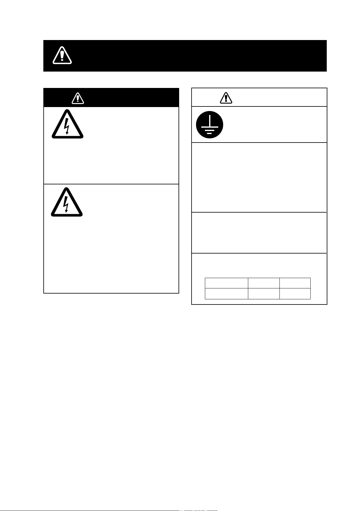
SAFETY INSTRUCTIONS
WARNING
Do not work inside the
equipment unless totally
familiar with electrical
circuits.
Hazardous voltage which can
cause electrical shock, burn
or serious injury exists inside
the equipment.
Turn off the power at the
mains switchboard before
beginning the installation.
Post a sign near the switch
to indicate it should not be
turned on while the equipment is being installed.
Fire, electrical shock or
serious injury can result if the
power is left on or is applied
while the equipment is being
installed.
CAUTION
Ground the display unit to
prevent loss of sensitivity
and mutual interference.
Confirm that the power supply voltage
is compatible with the voltage rating
of the equipment.
Connection to the wrong power supply
can cause fire or equipment damage. The
voltage rating appears on the label at the
rear of the display unit.
Use the correct fuse.
Use of a wrong fuse can cause fire or
equipment damage.
Keep the following compass safe
distances:
Standard Steering
Display unit 0.45 m 0.30 m
Page 3
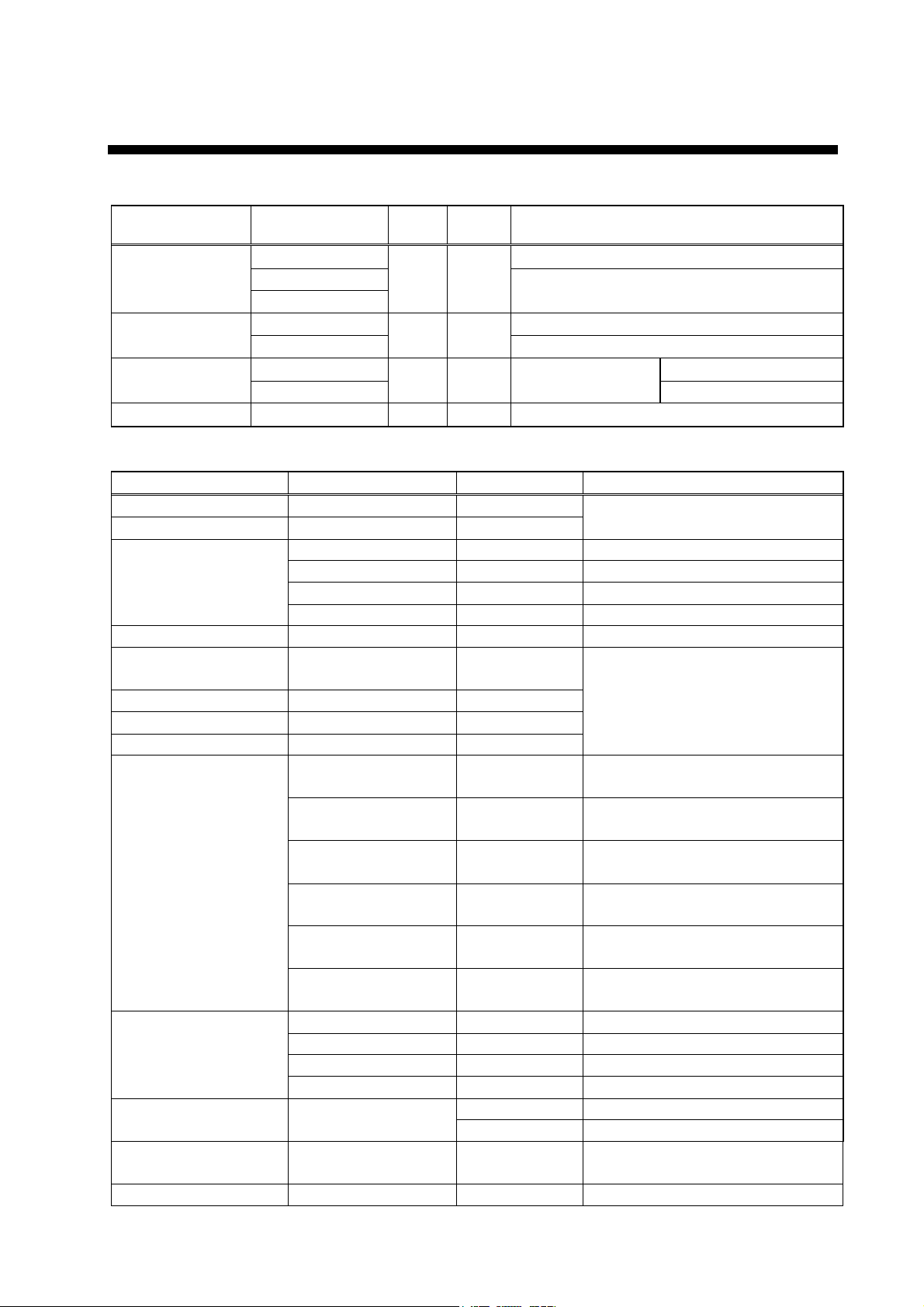
1. EQUIPMENT LIST
Standards
Name Type Q'ty
Mass
(kg)
GPA-017S
Antenna Unit
GPA-018S
GPA-019S
Display Unit
Materials
Spare Parts SP20-00500 1 set
GP-90-N Without Beacon RX
GP-90-A
CP20-01900 With Antenna Cable Installation
CP20-01950
1
1 2.2
1 set
For DGPS
With Beacon RX
See lists at end of
manual.
Options
Name Type Code No. Remarks
Flush Mount Kit S OP20-24 004-393-000
Flush Mount Kit F OP20-25 004-393-280
CP20-01700 004-372-110 CP20-01701+30 m cable
Antenna Cable Set
Antenna Cable Assy. TNC-PS-3D-15 000-133-670 15 m
Right Angle Antenna
Base
L-Type Antenna Base No.13-QA310 000-803-240
Handrail Antenna Base No.13-RC5160 000-806-114
Mast Mount Kit CP20-01111 004-365-780
Cable Assy
Beacon Receiver Set
Rectifier PR-62
DGPS Beacon
Receiver
Whip Antenna FAW-1.2 000-130-046 1.2 m
CP20-02700 004-381-160 CP20-02701+30 m cable
CP20-01710 004-372-120 CP20-01701+50 m cable
CP20-02710 004-381-170 CP20-02701+
No.13-QA330 000-803-239
MJ-A6SPF0011-050
(03S9202)
MJ-A6SPF0011-100
(03S9226)
MJ-A7SPF0003-050
(20S0241)
MJ-A6SPF0003-050C
(20S0093)
MJ-A6SPF0012-050C
(64S4073)
MJ-A6SPF0012-100C
(64S4071)
OP20-32-1 000-041-018 With GPA-018S
OP20-32 000-041-019 With whip antenna and OP20-32-1
OP20-33 000-041-596 With GPS-019S
OP20-34 000-041-598 Without whip antenna
GR-80 -
000-132-244 Cross Cable 5m, 6p-4p
000-132-336 Cross Cable 10m, 6p-4p
000-136-730-01 5m, For DATA4
000-154-054-10 5m
000-154-053-10 Cross cable 5m
000-154-037-10 Cross cable 10m
000-013-485 For 100VAC mains
000-013-486 For 220VAC mains
For display unit.
For antenna unit.
Remarks
Without Antenna Cable
50 m cable
1
Page 4
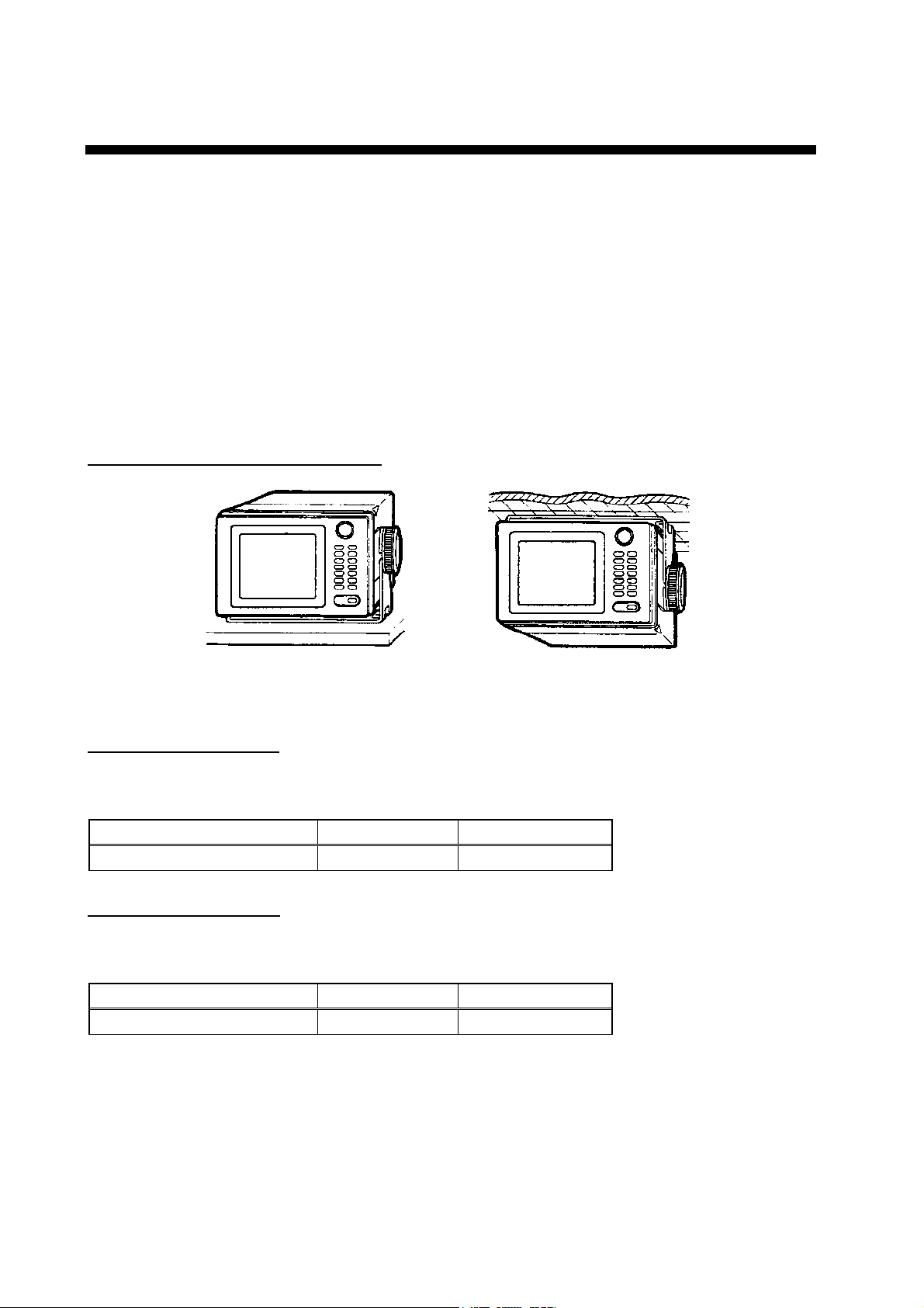
2. DISPLAY UNIT
The display unit can be installed with either of four methods as shown below. Refer to the
outline drawing at the end of manual.
• Locate the unit away from exhaust pipes and vents.
• The mounting location should be well ventilated.
• Mount the unit where shock and vibration are minimal.
• Keep the display unit away electromagnetic field generating equipment such as motor,
generator.
• Allow sufficient maintenance space and a sufficient slack in cables for maintenance and
repair.
Table Top and Overhead Mounting
T ABLE TOP OVERHEAD
Display unit mounting methods
Flush mounting type F
An optional flush mount kit type F is required. For details, see outline drawing at end of
manual.
Name Type Code No.
Flush Mount Kit F OP20-25 004-393-280
Flush mounting type S
An optional flush mount kit type S is required. For details, see outline drawing at end of
manual.
Name Type Code No.
Flush Mount Kit S OP20-24 004-393-000
2
Page 5
3. ANTENNA UNIT
Mounting
Install the antenna unit referring to the installation diagram at end of manual. When
selecting a mounting location for the antenna unit, keep in mind the following points.
• Select a location out of the radar beam. The radar beam will obstruct or prevent reception
of the GPS satellite signal.
• Be sure the location offers a clean line-of-sight to satellite. Objects within line-of-sight to
a satellite, for example, a mast or funnel, block reception and cause prolonged acquiring time
or interruption of position fix.
• Mount the unit as high as possible. Mounting the antenna as high as possible keeps it free
of water spray, which can intercept reception of GPS satellite signal, if water spray is frozen.
• The antenna unit GPA-018S must be grounded. Connect ground wire of 1.25 sq or larger
(local supply) between the antenna unit and a stainless steel screw fastened to the mast.
• The antenna unit GPA-018S must be taped. See chapter 7 for instructions.
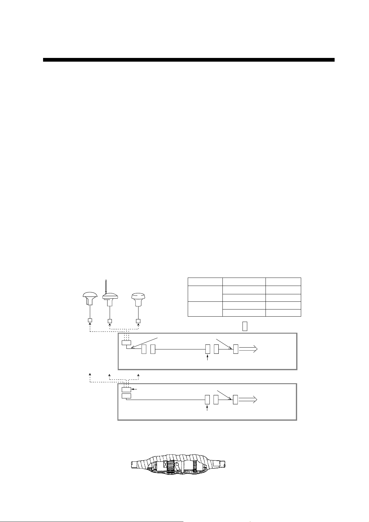
Extending Antenna Cable Length
The standard cable is 15m long. 30m and 50m long extension cable sets are optionally
available.
!Extension cable line-up
Fabricate the end of antenna cable and attach the coaxial connector. Details are shown
on next page.
GPA-019S
20cm
Antenna Unit
GPA-018S GPA-017S
Conversion Cable Assy.
Antenna Cable
1 m
For CP20-01700, CP20-01710
TNCP-NJ
For CP20-02700, CP20-02710
30 m or 50 m 1 m
Antenna Cable
30 m or 50 m
Cable length
30 m
50 m
Fabricate locally. (See the next page.)
OR
Conversion Cable Assy.
Fabricate locally. (See the next page.)
Necessary parts
1 m
CP20-01700
CP20-02700
CP20-01710
CP20-02710
: Connector
Code no.
004-372-110
004-381-160
004-372-120
004-381-170
To display unit
To display unit
Extension Cable Line-up
!Waterproofing the connector
Wrap connector with vulcanizing tape and then vinyl tape. Bind the tape end with
cable-tie.
How to waterproof the connector of the antenna cable
3
Page 6
3. ANTENNA UNIT
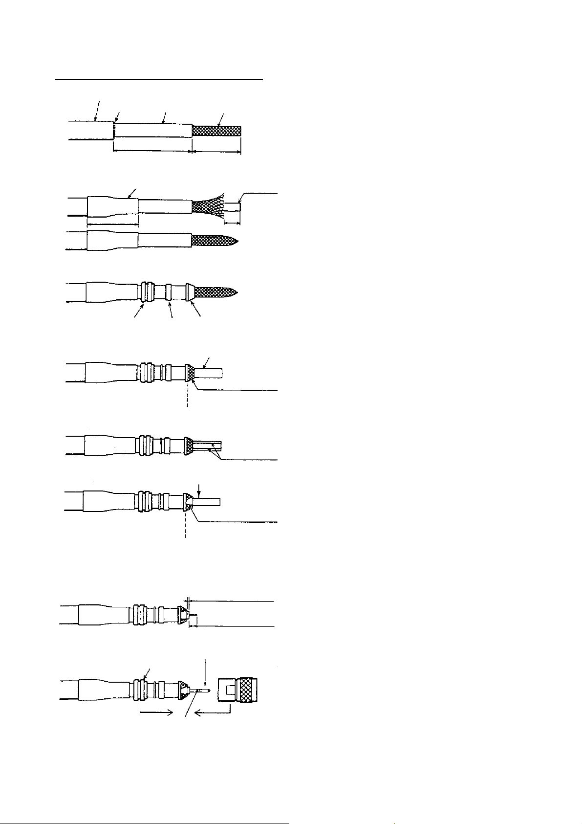
How to attach the N-P - 8DFB connector
Outer Sheath
Armor
Inner Sheath Shield
50
30
Remove outer sheath and armor by the dimensions
shown left.
Expose inner sheath and shield by the dimensions
shown left.
Cover with heat-shrink tubing and heat.
30
Clamp
Nut
Gasket
(reddish
brown)
Trim shield here.
Insulator
10
Clamp
Aluminum Foil
Cut off insulator and core by 10mm.
Twist shield end.
Clip on clamp nut, gasket and clamp as shown left.
Fold back shield over clamp and trim.
Cut aluminum foil at four places, 90° from one
another.
4
Fold back aluminum foil onto shield and trim.
Trim aluminum
tape foil here.
Clamp Nut
Solder through
the hole.
1
5
Pin
Shell
Expose the insulator by 1mm.
Expose the core by 5mm.
Slip the pin onto the conductor. Solder them together
through the hole on the pin.
Insert the pin into the shell. Screw the clamp nut into
the shell.
(Tighten by turning the clamp nut. Do not tighten by
turning the shell.)
Page 7
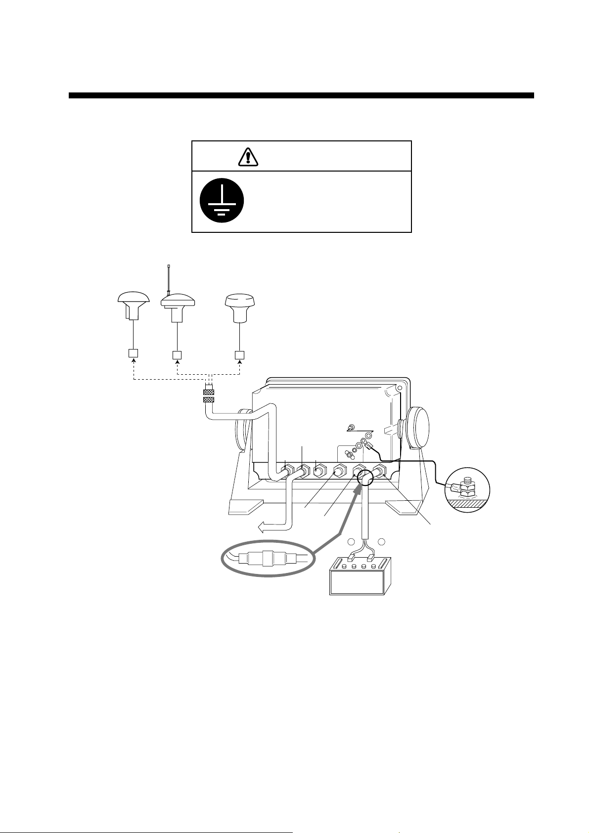
4. WIRING
The figure below shows the connection of cables on rear of display unit.
CAUTION
Ground the display unit to
prevent loss of sensitivity
and mutual interference.
Antenna Unit
GPA-019S
20cm
GPA-018S GPA-017S
External Equipment
Rear of Display Unit
DATA1
ANT
DATA2
DATA3
DATA4
–
Black Red
Ground
INPUT
+
12~24 VDC
FUSE 2A
Connection of cables on display unit
5
Page 8
4. WIRING
Grounding
The display unit contains several CPUs. While they are operating, they radiate noise, which
can interfere with other radio equipment. Ground the unit as follows to prevent it.
• The grounding wire should be 1.25sq or larger.
• The grounding wire should be as short as possible.
External Equipment
The DATA1, DATA2, and DATA3 ports are used to connect an external equipment such as
autopilot, remote display, navigation equipment. Refer to the interconnection diagram on
page S-1 for connection of DATA1, DATA2 and DATA 3 port. The DATA4 port is used to
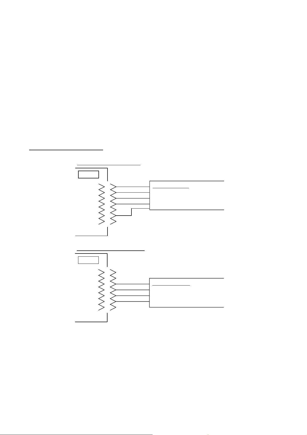
connect NMEA equipment, IBM-PC or DGPS beacon receiver as follows;
Connection of DATA4 port
In case of RS-422 Level
DATA4
TD-A
TD-B
RD-A
RD-B
S·G
1
2
3
4
5
6
7
In case of RS-232C Level
DATA4
1
2
RD
NC
SD
S·G
3
4
5
6
7
RS-422 level
IBM PC
Beacon Receiver
NMEA equipment
RS-232C level
IBM PC
Beacon Receiver
NMEA equipment
NOTE: See page 15 for selection of input/output signal.
6
Page 9
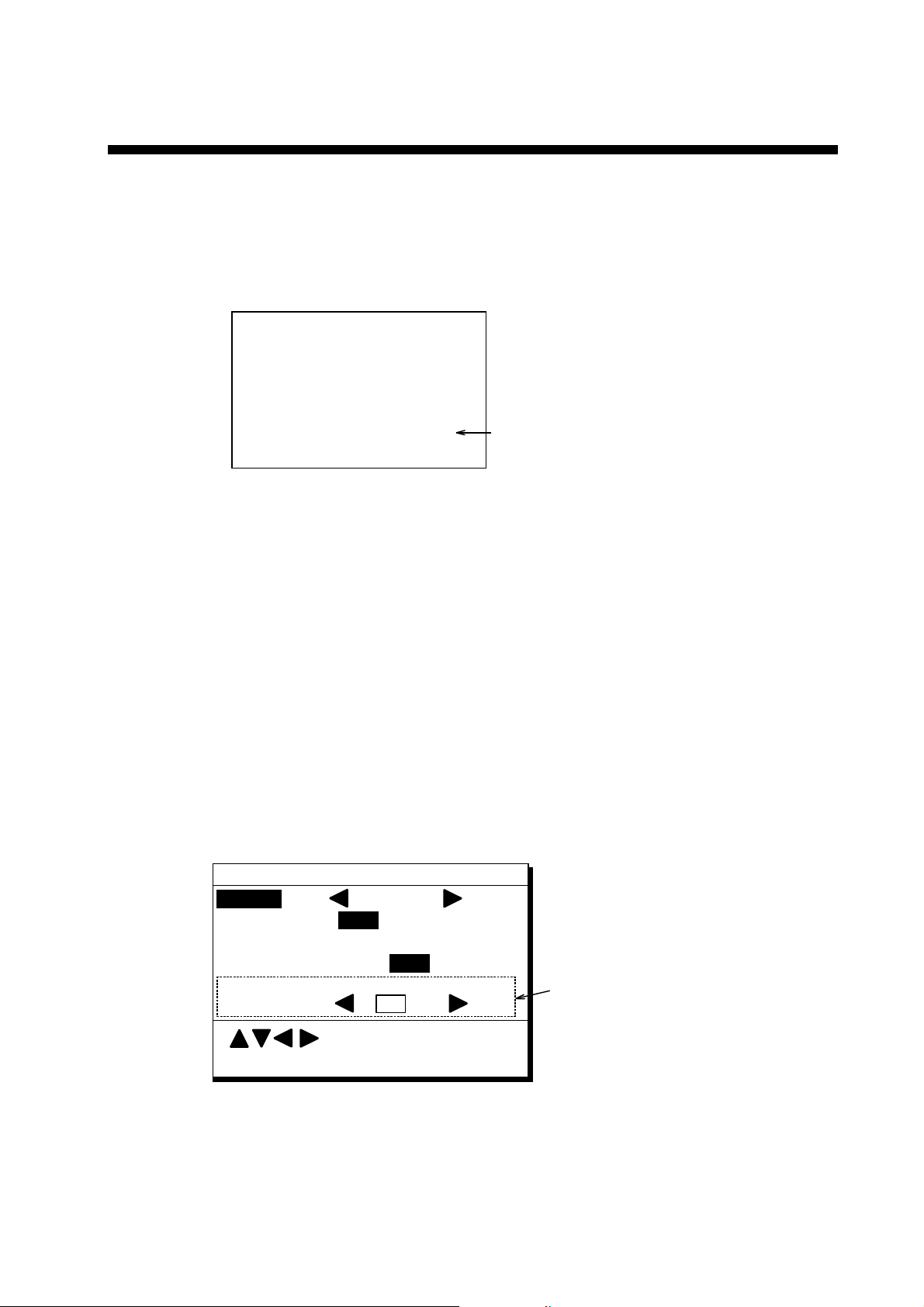
5. INITIAL SETTINGS
Checking Operation
1. Turn on the GP-90.
2. Confirm that "OK" and "BEACON RCVR INSTALLED" are displayed on the self-test
display.
PROGRAM MEMORY =OK
SRAM =OK
Internal Battery
=OK
BEACON RCVR INSTALLED
DATA 3: DATA OUTPUT
Confirm that "BEACON RCVR
INSTALLED" is displayed when
DGPS function is provided.
Self-test display at equipment start up
3. Press [MENU ESC], [8] and [1]. Confirm that "BEACON OK" is displayed.
DGPS Setup
The default setting is "manual".
Automatic DGPS setup
The beacon receiver (GR-7000A) can automatically select optimum reference station by
feeding GP-90’s position data. If it takes more than 5 minutes to fix DGPS position at the
automatic mode, switch to manual mode. Use the manual mode when an external beacon
receiver has no automatic function of station selection.
1. Press [MENU ESC], [9] and [7] to display the DGPS SETUP menu.
WAAS/DGPS SETUP
MODE
WAAS SEARCH
CORRECTIONS DATA SET 00
DGPS Station
Freq.
Baud Rate
GPS
Auto Man (GEO= )___
Auto
288.0kHz
Man
200 bps
(ID= )
___
These items appear when
"Man" is selected.
:Select
ENT: Enter MENU: Escape
Figure 5-1 DGPS SETUP menu
2. Press S or T to select DGPS MODE and press W to select “INT BEACON”.
3. Press
4. Press
S or T to select DGPS Station.
W to select Auto.
7
Page 10
5. INITIAL SETTINGS
5. Press the [NU/CU ENT] key.
6. Press the [MENU ESC] key.
Manual DGPS setup
Enter four digit ID number, frequency and baud rate of station.
1. Press [MENU ESC], [9] and [7] to display the DGPS SETUP menu.
2. Press
3. Press
4. Press
5. Enter four digit ID number. You can clear an entry by the [CLEAR] key.
If there is no ID number, press the [NU/CU ENT] key.
6. Press the [NU/CU/ENT] key.
If the number entered is invalid, the buzzer sounds and the message "INVALID ID" appears
on the display for three seconds.
7. Enter frequency in four digits (283.5 kHz to 325.0 kHz).
8. Press the [NU/CU ENT] key. "Baud Rate" appears in reverse video.
9. Press
10. Press the [MENU ESC] key.
S or T to select DGPS MODE and press W to select “INT BEACON”.
S or T to select DGPS Station.
W to select Man.
W or X to select baud rate; 25, 50, 100 or 200bps.
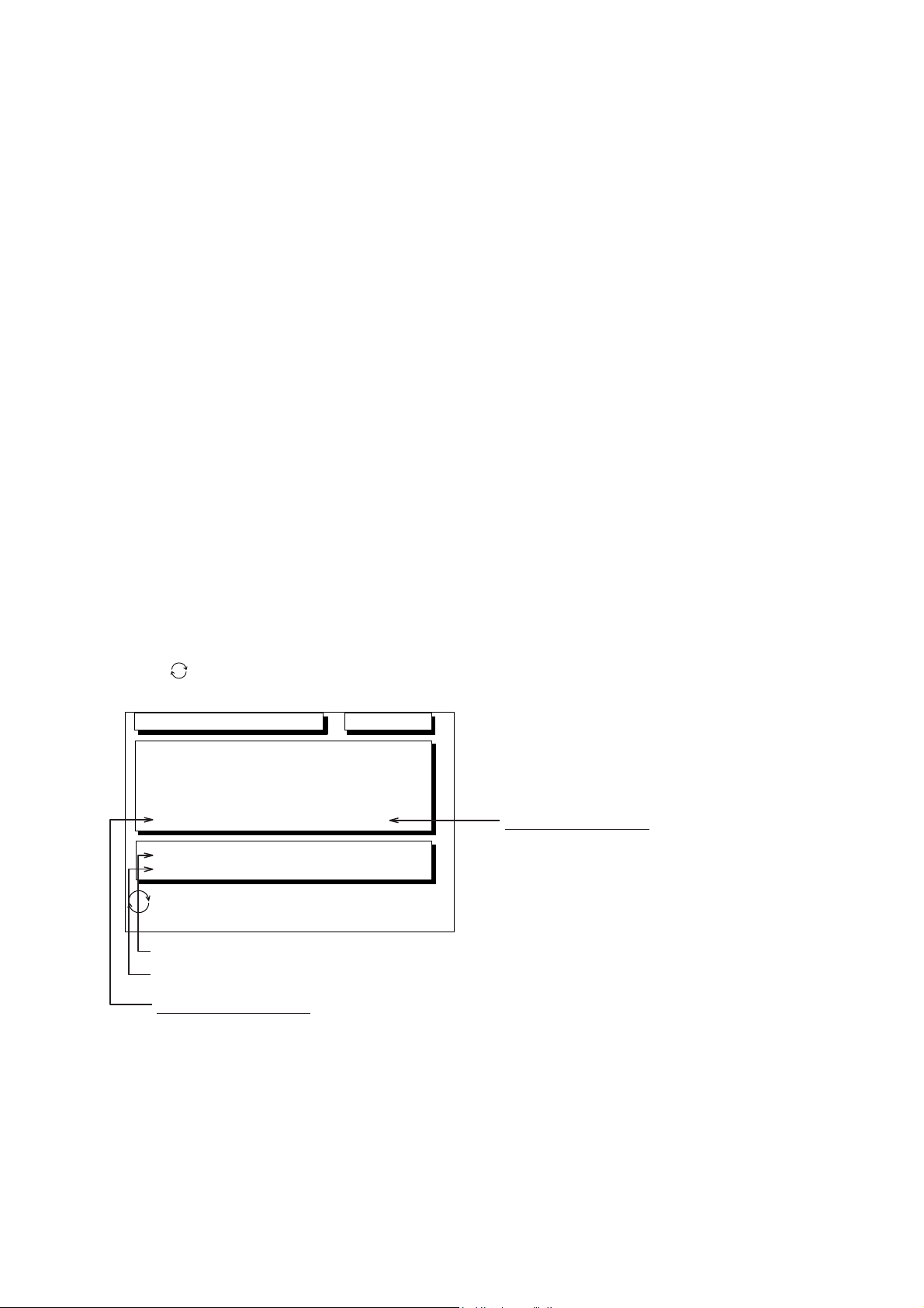
DGPS Operation checking
1. Press [MENU ESC] and [7].
2. Press [
MENU:Escape
] several times to display the following.
Jan 21 2005 23:59’59" U
DGPS INTEGRITY STATUS
_ _ _ _ _ _ _ _ _ _ _ _ _ _ _ _ _ _ _ _ _ _ _ _ _
NAME:
ID: 274
Bit Rate: 200 bps
Sig Strength: 83 dB
DGPS DATA: Good
BEACON STATION:
:STATION MESSAGE
Beacon signal status
Reference station status
DGPS signal strength
This value is between 1and 84.
The higher the value,
the stronger the signal.
If a noise appears at reception band width,
the value becomes bigger.
SNR: 21 dB
Good
D3D 100m
SAFE
Health: 0
Freq: 323.0 kHz
Signal to noise ratio
This value is between 1 to 22. The higher
the value, the better the reception of
beacon signal. When this value is less
than 20, the error is included in the
correction data. In this time, position
fixing is done by using past position data.
When the ship is in the service area of a
beacon station, this value should be 21 or
22. If not, check as follows.
• Check the grounding.
• Check the radar beam interference.
• Check the noise of power generator of
the ship.
8
Figure 5-2
Page 11

5. INITIAL SETTINGS
Input/Output Setting
The GP-90 can output navigation information to external equipment. For example, it can
output position data to a radar or echo sounder for display on their display screen. You can
convert a Loran Plotter to a GPS Plotter with position data from the GP-90.
Before selecting data to output, confirm what data the external equipment requires. Output
necessary data only. Outputting unnecessary data can cause receiving problems at the
external equipment.
Talker
All data transmitted by marine electronics equipment is prefixed with a two-character code
which tells external equipment what equipment is transmitting data. This two-character code
is called the talker. The GP-90 contains the talkers GP, LC and DE.
Because GPS is a relatively new system some early model equipments do not recognize
the GP talker name. In this case transmit data using a conventional talker, which equipment
recognizes, such as Loran C.
9
Page 12

5. INITIAL SETTINGS
Data format and data output availability
Outpu t data sen t ence of IEC 61162-1 and NMEA 0183 Ver. 1.5/2.0.
AAM: Waypoint arrival alarm
APB: Autopilot sentence B
magnitude of cross track error, direction to steer, arrival alarm, bearing to waypoint
("Heading to steer to destination waypoint data" not used)
BOD: Bearing-origin to destination
BWC: Bearing and distance to waypoint-great circle
BWR: Bearing and distance to waypoint-rhumb line
BWW: Bearing-waypoint to waypoint
DTM: Datum reference
GGA: Global positioning system (GPS) fix data
time of fix, latitude, longitude, quality indicator, number of satellites in use, DOP,
altitude, geoidal separation
("age of dgps data" and "differential reference station ID" not used)
GLL: Geographic position-latitude/longitude
GNS: GNSS fix data
GBS: GPS satellite fault detection
RMB: Recommended minimum navigation information cross track error, direction to steer,
origin and destination waypoint ID, destination waypoint latitude and longitude,
range and bearing of destination waypoint, destination closing velocity, arrival
alarm
RMC: Recommended minimum specific GPS/TRANSIT data
UTC of position fix, latitude and longitude, ground speed and course, date,
magnetic variation
RTE: Routes
VDR: Set and drift
VTG: Course over ground and ground speed
WCV: Waypoint closure velocity
WPL: Waypoint location
XTE: Cross-track error, measured
ZDA: Time and date
Rnn: Routes
Also, following NMEA 0183 Ver. 1.5 sentence is output.
APA: Autopilot sentence "A"
magnitude of cross track error, direction to steer, arrival alarm, bearing origin to
destination.
10
Page 13

5. INITIAL SETTINGS
Input data sentence of NMEA 0183 Ver. 1.5/2.0
Checksum is checked if attached, and if any errors are found, the sentence becomes invalid.
Talker ID is not distinguished.
DBT: Depth below transducer
DPT: Depth
HDG: Heading, deviation and variation
HDM: Heading, magnetic
HDT: Heading, true
MTW : W ater temperature
TLL: Target latitude and longitude
VBW: Dual ground/water speed
VHW: Water speed and heading.
FURUNO proprietary sentence
AGFPA: Autopilot information from FURUNO autopilot equipments.
11
Page 14

5. INITIAL SETTINGS
AGFPA: Autopilot information from FURUNO autopilot equipments
Port Input Output
DATA1
DATA2
NMEA 0183
Ver. 1.5 /2.0
AGFPA , DBT, DPT,
HDG, HDM, HDT,
MTW, TLL, VBW,
VHW
(Selected by menu)
IEC 61162-1/NMEA 0183 Ver.1.5/
Ver.2.0
AAM, APA, APB, BOD, BWC, BWR,
BWW, GGA, GLL, GNS, RMB, RMC,
VDR, VTG, WCV, WPL, XTE, ZDA,
GBS, Rnn, RTE
LOG PULSE DATA3 External MOB
Same as the data output form “DATA1”
General data DATA4 DGPS or general data
IEC 61162-1/NMEA 0183 Ver.1.5/
Ver.2.0
AAM, APA, APB, BOD, BWC, BWR,
BWW, GGA, GLL, GNS, RMB, RMC,
VDR, VTG, WCV, WPL, XTE, ZDA,
GBS, Rnn, RTE
General data
1) Input of waypoint data
Connect YEOMAN equipment to DATA4 port.
2) Input and output of waypoint / route data
Rate of operation
The TX rate of operation is the percentage of data output in one second, and it appears on
the screen. If short intervals are assigned to many sentences, the rate of operation
increases as illustrated below
Note: Output data should be less than 100%.
When the external equipment cannot display correct data input from the GP-90, the rate of
operation should be lowered. For example, set a rate of operation less than 60 % for the
Temperature Indicator TI-20.
TX TX TX
12
Page 15

5. INITIAL SETTINGS
DATA 1 output sett i n g
1) Press [MENU], [9] and [3]. The DATA 1, 3 OUTPUT SETUP menu appears.
DATA 1, 3 OUTPUT SETUP
Data Fmt. V1.5 V2.0 IEC
Talker ID GP LC DE
Output Data (00-90 sec) 100%
1. AAM:00 APA:00 APB:04 BOD:00
2. BWC:00 BWW:00 GGA:00 GLL:01
3. RMB:01 RMC:00 VTG:01 WCV:00
4. VDR:00 WPL:00 XTE:00 ZDA:01
5. GNS:00 GBS:01 Rnn:00 RTE:00
DATA3. Log Pulse
200ppm
400ppm
ENT : Enter
Settings shown here are default settings.
This line appears only when LOG is
selected by internal jumper wires.
MENU : Escape
Figure 5-3 DATA 1, 3 OUTPUT SETUP m enu
2) Press
3) Press
S or T to select Data Fmt.
W or X to select V1.5, V2.0 or IEC.
4) Press the [ENT] key. Talker ID appears in reverse video.
5) Press
W or X to select GP, LC or DE.
6) Press the [ENT] key.
7) Enter Tx interval for each output data sentence in line 1. Tx interval is available in 00,
01, 02, 03, 04, 05, 06, 10, 15, 20, 30, 60, and 90 sec.
8) Press the [ENT] key.
9) Enter Tx interval for each output data sentence in lines 2 through 5. Press the [ENT] key
after setting each line.
In great circle navigation, BWC and WNC are output but BWR and WNR are not. In rhumb
line navigation, BWR and WNR are output but BWC and WNC are not.
The total data output are shown by percentage on the third line.
13
Page 16

5. INITIAL SETTINGS
DATA 2 output settin g
1) Press [MENU], [9] and [4]. The DATA 2 OUTPUT SETUP menu appears.
DATA2 OUTPUT SETUP
Data Fmt.
Talker ID GP LC DE
Output Data (00-90 sec) 100%
1. AAM:00 APA:00 APB:04 BOD:00
2. BWR:00 BWW:00 GGA:00 GLL:01
3. RMB:01 RMC:00 VTG:01 WCV:00
4. VDR:00 WPL:00 XTE:00 ZDA:01
5. GNS:00 GBS:01 Rnn:00 RTE:00
: Select
ENT : Enter
V1.5
MENU : Escape
V2.0
IEC
Setting shown here are default settings.
Figure 5-4 DATA 2 OUTPUT SETUP menu
2) Follow the procedure for setting DATA 1 output.
DATA 3 output sett i n g
The DATA 3 can output NMEA 0183 (V1.5/V2.0) /IEC 61162-1 data or log pulse by
selecting inner jumper wires. For NMEA 0183 (V1.5/V2.0) /IEC 61162-1, the same signal of
DATA 1 is output from DATA 3.
Selection of NMEA0183 or log pulse
Output data
NAV board
JP4 (2 pcs.) ON OFF
JP5 (3 pcs.) OFF ON
Rate of log pulse output
NMEA 0183 (V1.5/
V2.0)/IEC 61162-1
(default setting)
Log pulse
500 mA Max.
50 VDC
Procedure for setting of log pulse rate
1) Press [MENU], [9] and [3].
2) Press
3) Press
S or T to select DATA 3. Log Pulse.
W or X to select log pulse for external equipment; 200 ppm or 400 ppm.
4) Press the [ENT] key.
5) Press the [ESC] key.
14
Page 17

Setting DATA 4 to Data Output
1) Press [MENU], [9] and [5]. The DATA 4 I/O SETUP menu appears.
DATA 4 I/O SETUP 1/2
DATA 4. Level RS232C RS422
Data Out Com. DGPS
To Next Page
: Select
ENT : Enter MENU : Escape
Appears only when external
2) Press
3) Press
S or T to select DATA4. Level.
W or X to select level of external equipment; RS232C or RS422.
4) Press the [ENT] key.
5) Press
6) Press
W or X to select Out.
T to select to Next Page. The DATA 4 I/O SETUP <out> menu appears.
DGPS receiver is used.
Figure 5-5 DATA 4 I/O SETUP menu
5. INITIAL SETTINGS
DATA 4 I/O SETUP <Out> 2/2
To Previous Page
Data Fmt. V1.5 V2.0 IEC
Talker ID GP LC DE
Output Data (00-90 sec) 100%
1. AAM:00 APA:00 APB:04 BOD:00
2. BWR:00 BWW:00 GGA:00 GLL:01
3. RMB:01 RMC:00 VTG:01 WCV:00
4. VDR:00WPL:00 XTE:00 ZDA:01
5. GNS:00 GBS:01 Rnn:00 RTE:00
ENT : Enter
MENU : Escape
Figure 5-6 DATA 4 I/O SETUP <out> menu
7) Follow "DATA 1 output setting" from step 2.
15
Page 18

5. INITIAL SETTINGS
Setting DATA 4 to “COM.” (general data)
Waypoints and Routes data can be received from a personal computer, through the DATA
4 port.
1) Press [MENU], [9] and [5].
!
2) Press
3) Press
4) Press the [ENT] key.
5) Press
6) Press
or " to select DATA4. Level.
#
or $ to select level of personal computer; RS232C or RS422.
$
to select Com.
"
to select To Next Page. The DATA 4 I/O SETUP <Com.> menu appears.
DATA 4 I/O SETUP <Com.> 2/2
To Previous Page
Baud Rate 9600 bps
L WPT
Load Data
Command Stop Start
Save Data WPT/RTE
Command Stop Start
WPT/RTE
: Select
ENT : Enter
MENU : Escape
Figure 5-7 DATA 4 I/O SETUP <Com.> menu
7) Press
8) Press
!
or " to select Baud Rate.
#
or $ to select baud rate; 4800bps, 9600bps or 19200bps.
9) Press the [ENT] key.
#
10) Press
11) Press
or $ to select WPT/RTE.
"
to select Command. Stop, on the same line as Command, appears in reverse
video.
$
12) Press
to select Start. The message shown in Figure 5-8 appears.
Loading erases current data
and stops Route navigation
Are you sure to load?
ENT: Yes MENU: No
Figure 5-8
13) Press the [ENT] key. The message shown in Figure 5-9 appears while data is being
loaded.
Now loading
Waypoint/Route data !
MENU: Stop
Figure 5-9
16
Page 19

5. INITIAL SETTINGS
14) Output data from the computer. When loading data is completed, the cursor shifts to
Stop.
15) Press the [ESC] key.
Setting DATA 4 to DGPS
An external DGPS receiver can be connected to the DATA 4 port.
Follow the procedure below to setup the GP-90 according to the specifications of the DGPS
receiver.
1) Press [MENU], [9] and [5].
!
2) Press
3) Press
4) Press the [ENT] key.
5) Press
6) Press
or " to select Level.
#
or $ to select level; RS232C or RS422.
#
or $ to select DGPS.
"
to select To Next Page.
DATA 4 I/O SETUP <DGPS> 2/2
To previous Page
First Bit
Parity
Stop Bit
Baud Rate
MSB LSB
EVEN ODD NONE
12
4800 9600
Figure 5-10 DATA 4 I/O SETUP <DGPS> menu
!
7) Press
8) Press
9) Press
10) Press
11) Press
12) Press
13) Press
14) Press
or " to select First Bit.
#
or $ select first bit; MSB or LSB.
"
to select Parity.
#
or $ to select parity bit; EVEN, ODD or NONE.
"
to select Stop Bit.
#
or $ to select stop bit; 1 or 2.
"
to select Baud Rate.
#
or $ to select baud rate; 4800 or 9600.
15) Press the [ENT] key.
16) Press the [ESC] key.
: Select
ENT: Enter MENU: Escape
17
Page 20

6. OPTIONAL DGPS
Beacon Receiver Set GR-80
GP-90
DATA4
RS-422*
NP Board
JP3
Open
TD-A
TD-B
RD-A
RD-B
GND
1
2
3
4
5
6
7
WHT
BLK
YEL
GRN
BLU
4
P
3
2
P
1
7
DATA
RD-A
RD-B
TD-A
TD-B
GND
GR-80
RS-422
Whip
Antenna
Preamp unit (with
15 m cable)
* This connection is required for L/L Auto mode of GR-80.
When the GP-90 is connected with Beacon Receiver GR-80, do the setting as follows.
Signal level RS-422 *1
First Bit LSB
Parity NONE
Stop Bit 1
Baud Rate 4800 or 9600 *1
*1: Coincide with the setting of the Beacon Receiver GR-80.
Refer to page 17 for DGPS setup.
18
Page 21

7. TAPING ANTENN A UNIT GPA-018S
After inserting the whip antenna to the antenna base of GPA-018S, tape the antenna base
and whip antenna with self-vulcanizing tape and vinyl tape to reinforce the whip antenna.
1. Wrap the antenna junction point with butyl 15 tape or the equivalent.
How to wrap
1) Pull the tape to be about two times in length and wind it up, overlapping by 1/2 the width
of the tape.
2) Wrap from bottom to top, i.e., from right to left as in the picture below.
Whip antenna
Butyl tape
3) Wrap the tape from the base to a point about 60 mm, and then back to the base.
Keep tension on edge of tape, using finger to hold tape. Then, squeeze edges of tape
with thumb and index finger.
Base
Wrap approx.
60 mm
Antenna
2. Completely cover the butyl rubber tape with white vinyl tape, wrapping from the base to
the last wind of butyl tape and then back to the base.
How to wrap
1) Being careful not to pull the tape too tightly, wind tape, overlaping by approx. 1/3 of tape
width.
2) Squeeze edges of tape with thumb and index finger.
White vinyl tape
19
Page 22

2
A-1
1
(*2)
1
1
1
1
1
20AX‑X‑9851
1/1
NO.6348SUS303
20AX‑X‑9851‑4
NAME OUTLINE Q'TYDESCRIPTION/CODE№
**
000‑805‑906
TNC‑PS‑3D‑
1520S0216
000‑133‑670
MJ‑A2SPF0014‑
030C
000‑158‑000
MJ‑A6SPF0003‑050C
000‑154‑054
IMJ‑4427*‑*
000‑147‑467
OSJ‑4427*‑*
**
000‑147‑465
**
OMJ‑4427*‑*
000‑147‑463
パーカークランプ
GP‑90‑**‑*1‑**/GP‑90‑DUAL‑**‑*1‑**
その他工材 OTHERINSTALLATIONMATERIALS
HOSECLAMP
1
GP‑90‑E‑N
ケーブル組品
**
000‑041‑054
GPA‑019S
ANTENNACABLEASSY.
ケーブル組品MJ
POWERCABLE
1
(*1)
**
000‑142‑545
1
(*1)
GPA‑018S
**
000‑041‑895
ケーブル組品MJ
1
GPA‑017S
図書 DOCUMENT
SIGNALCABLEASSEMBLY
(*1)
**
000‑040‑537
装備要領書
3
SP20‑00500
FGBO‑A2AAC 125V
INSTALLATIONMANUAL
操作要領書
OPERATOR'SGUIDE
取扱説明書
4
CP20‑01101
000‑549‑062
5X20SUS304
CP20‑01111
000‑802‑081
OPERATOR'SMANUAL
1
20‑007‑3012‑1
1
100‑183‑271
20‑007‑3011‑2
3.(*2)のアンテナケーブル組品は、有り・無しの仕様が有ります。
AVAILABLEWITHORWITHOUTANTENNAU N I T.
100‑183‑262
PACKING LIST
NAME OUTLINE Q'TYDESCRIPTION/CODE№
ユニット UNIT
受信演算部
DISPLAYUNIT
空中線部
ANTENNAUNIT
空中線部
ANTENNAUNIT
空中線部
ANTENNAUNIT
予備品 SPAREPARTS
FUSE
工事材料 INSTALLATIONMATERIALS
+トラスタッピンネジ 1種
ヒューズ
空中線部工材 ANTENNAUNITINSTALLATIONMATERIALS
SELF‑TAPPINGSCREW
取付補助金具
INSTALLINGSPACER
パイプ
PIPE
1.コ-ド番号末尾の[**]は、選択品の代表コ-ド番号を表します。
CODENUMBERENDEDBY"**"INDICATESTHENUMBER OFTYPICALMATERIAL.
2.(*1)の空中線部は仕様により決定されます。
ANTENNAUNITHASBEENDETERMINEDBYSPECIFICATION.
(略図の寸法は、参考値です。DIMENSIONSINDRAWINGFORREFERENCEONLY.)
Page 23

1
A-2
1
1
1
20AX‑X‑9852
1/1
MJ‑A6SPF0003‑050C
20AX‑X‑9852‑4
NAME OUTLINE Q'TYDESCRIPTION/CODE№
**
000‑154‑054
OMJ‑4427*‑*
000‑147‑463
OSJ‑4427*‑*
**
000‑147‑465
**
IMJ‑4427*‑*
000‑147‑467
ケーブル組品MJ
GP‑90‑**‑*O‑**/GP‑90‑DUAL‑**‑*0‑**
図書 DOCUMENT
SIGNALCABLEASSEMBLY
1
GP‑90‑E‑N
取扱説明書
1
**
000‑041‑054
GPA‑019S
OPERATOR'SMANUAL
操作要領書
OPERATOR'SGUIDE
装備要領書
1
(*1)
**
000‑142‑545
(*1)
**
GPA‑018S
000‑041‑895
GPA‑017S
INSTALLATIONMANUAL
1
(*1)
**
000‑040‑537
3
SP20‑00500
FGBO‑A2AAC 125V
3.(*2)のアンテナケーブル組品は、有り・無しの仕様が有ります。
AVAILABLEWITHORWITHOUTANTENNAU N I T.
4
CP20‑01101
000‑549‑062
5X20SUS304
000‑802‑081
1
TNC‑PS‑3D‑
1520S0216
(*2)
000‑133‑670
1
MJ‑A2SPF0014‑
030C
000‑158‑000
PACKING LIST
NAME OUTLINE Q'TYDESCRIPTION/CODE№
ユニット UNIT
受信演算部
DISPLAYUNIT
空中線部
ANTENNAUNIT
空中線部
ANTENNAUNIT
空中線部
ANTENNAUNIT
予備品 SPAREPARTS
FUSE
工事材料 INSTALLATIONMATERIALS
+トラスタッピンネジ 1種
ヒューズ
その他工材 OTHERINSTALLATIONMATERIALS
SELF‑TAPPINGSCREW
ケーブル組品
ANTENNACABLEASSY.
ケーブル組品MJ
POWERCABLE
1.コ-ド番号末尾の[**]は、選択品の代表コ-ド番号を表します。
CODENUMBERENDEDBY"**"INDICATESTHENUMBER OFTYPICALMATERIAL.
2.(*1)の空中線部は仕様により決定されます。
ANTENNAUNITHASBEENDETERMINEDBYSPECIFICATION.
(略図の寸法は、参考値です。DIMENSIONSINDRAWINGFORREFERENCEONLY.)
Page 24

Antenna Cable Set
C0014‑M20‑E
A-3
CP20-01700 (004-372-110)
CP20-01710 (004-372-120)
工事材料表
INSTALLATIONMATERIALS
番号
NO.
1
2
3
4
名 称
NAME
変換ケーブル組品
CONVERTCABLEASSY.
ビニルテープ
VINYLTAPE
コネクタ(N)
CONNECTOR
絶縁テープ
SELF‑BONDINGTAPE
略 図
OUTLINE
CODENO.
TYPE
NJ‑TP‑3DXV‑1
CODE
NO.
NO3600.2X19X10000
CODE
NO.
N‑P‑8DFB‑CF
CODE
NO.
Uテープ 0.5X19X5M
Uテープ 0.5X19X5M
CODE
NO.
004‑372‑420‑00
CP20‑01701
型名/規格
DESCRIPTIONS
000‑123‑809‑00
000‑835‑215‑00
000‑156‑918‑10
000‑165‑833‑10
000‑800‑985‑00
数量
Q'TY
2
1
1
1
20AG‑X‑9405
用途/備考
REMARKS
‑4
1/1
工事材料表
INSTALLATIONMATERIALS
番号
NO.
1
2
名 称
NAME
アンテナケーブル組品
ANTENNACABLEASSY.
アンテナケーブル組品
CABLEASSY.
CODENO.
TYPE
GP‑80,GP‑90,SC‑55,GP‑3500/F,GP‑
1850,GP‑1650,FA‑100,FA‑150,GP‑
1640/F,SC‑60/120,GD/GP‑
略 図
OUTLINE
8D‑FB‑CV*30M*
CODE
NO.
8D‑FB‑CV*50M*
CODE
NO.
型名/規格
DESCRIPTIONS
000‑111‑547‑00
000‑117‑599‑00
20AG‑X‑9404
数量
Q'TY
選択 TOBESELECTED
1
選択 TOBESELECTED
1
‑2
1/1
用途/備考
REMARKS
Page 25

Antenna Cable Set
A-4
CP20-02700 (004-381-160)
CP20-02710 (004-381-170)
工事材料表
INSTALLATIONMATERIALS
番号
NO.
1
2
3
4
5
名 称
NAME
変換ケーブル組品
CONVERTCABLEASSY.
ビニルテープ
VINYLTAPE
コネクタ(N)
CONNECTOR
コネクタ
CONNECTOR
絶縁テープ
SELF‑BONDINGTAPE
略 図
OUTLINE
CODENO.
TYPE
NJ‑TP‑3DXV‑1
CODE
NO.
NO3600.2X19X10000
CODE
NO.
N‑P‑8DFB‑CF
CODE
NO.
TNCP‑NJ
CODE
NO.
Uテープ 0.5X19X5M
Uテープ 0.5X19X5M
CODE
NO.
004‑381‑190‑00
CP20‑02701
型名/規格
DESCRIPTIONS
000‑123‑809‑00
000‑835‑215‑00
000‑156‑918‑10
000‑156‑599‑10
000‑165‑833‑10
000‑800‑985‑00
数量
Q'TY
1
1
1
1
1
20AX‑X‑9401
用途/備考
REMARKS
‑5
1/1
工事材料表
INSTALLATIONMATERIALS
番号
NO.
1
2
名 称
NAME
アンテナケーブル組品
ANTENNACABLEASSY.
アンテナケーブル組品
CABLEASSY.
CODENO.
TYPE
GP‑80,GP‑90,SC‑55,GP‑3500/F,GP‑
1850,GP‑1650,FA‑100,FA‑150,GP‑
1640/F,SC‑60/120,GD/GP‑
略 図
OUTLINE
8D‑FB‑CV*30M*
CODE
NO.
8D‑FB‑CV*50M*
CODE
NO.
型名/規格
DESCRIPTIONS
000‑111‑547‑00
000‑117‑599‑00
20AG‑X‑9404
数量
Q'TY
選択 TOBESELECTED
1
選択 TOBESELECTED
1
‑2
1/1
用途/備考
REMARKS
Page 26

Apr.18'03
D-1
Page 27

Apr.18'03
D-2
Page 28

Apr.18'03
D-3
Page 29

. Hatai
hatai
2005.12.19
11:57:12
+09'00'
D-4
Page 30

Sep.29'05
D-5
Page 31

Feb. 19, '03
D-6
Page 32

Feb. 19, '03
D-7
Page 33

D-8
Page 34

RD-A
S-1
RD-B
TD-H
TD-C
入出力データ、センテンスについては
装備要領書を参照のこと。
USING I/O DATA SENTENCES.
REFER TO INSTALLATION MANUAL FOR
TD-H
RD-B
RD-A
TD-C
RD-A
RD-B
リモートイベントスイッチ
(MOBスイッチ)
REMOTE EVENT SWITCH
(Man Over Board SWITCH)
外部GPSビーコン受信機またはパソコンを接続するときは
装備要領書を参照のこと。
REFER TO INSTALLATION MANUAL TO CONNECT EXTERNAL
DGPS BEACON RECEIVER OR PC.
GP-90
GPS航法装置
相互結線図
GPS NAVIGATOR
INTERCONNECTION DIAGRAM
クロ BLK
シロ WHT
ミドリGRN
キ YEL
MJ-A6SPF0003-050C,5m,φ6
*3
MJ-A6SPF
12345
J5
TD-A
*4
DATA1
DISPLAY UNIT
受信演算部
P
RD-H
TD-B
NMEA0183 V1.5
IEC61162-1/
GP-90
34
P
RD-C
MJ-A6SPF0012-050C/100C,5/10m,φ6,6P-6P
6
NC
GND
2
TNC-J-3*3TNC-P-3
0.2m
GPA-017S
ANTENNA UNIT
GPA-019S
*3
TNC-J-3
0.2m
1
空中線部
クロ BLK
シロ WHT
MJ-A6SPF0003-050C,5m,φ6
MJ-A6SPF0011-050/100,5/10m,φ6,6P-4P
*3
P
MJ-A6SPF
12345
J7
TD-B
TD-A
*4
DATA2
IEC61162-1/
GPS ANT
J12
*3
TNC-P-3
*3
*3
TNC-P-3
ミドリGRN
キ YEL
P
RD-C
RD-H
NMEA0183 V1.5
GND
ANT
1
2
TNC-PS-3D-15,15m,φ5.3
*3
6
NC
GND
N-J-3
NJ-TP-3DXV,1m
または OR
*3
*3
N-P-8DFB
GPA-018S
1.2m WHIP
*1GND
IV-2sq.
TNCP-NJ
MJ-A6SPF0003-050C,5m,φ6
*3
MJ-A6SPF
J6
DATA3
TNC-P-3
*2
1m
NJ-TP-3DXV
N-J-3
N-P-8DFB
*2
8D-FB-CV,30/50m,φ14.3
クロ BLK
シロ WHT
ミドリGRN
キ YEL
P
P
12345
NC
MOB-H
MOB-C
OR
TD-A/ALM-H
TD-B/ALM-C
*5
LOG PULSE OUT
NMEA0183 V1.5
IEC61162-1/
ケーブル長さは15/30/50mの選択または支給なし。
SELECT CABLE LENGTH FROM 15/30/50m SET OR NO SUPPLY.
MJ-A7SPF0003-050,5m,φ6
キ YEL
クロ BLK
ミドリGRN
シロ WHT
*3
MJ-A7SPF
6
GND
MOB IN
1
J8
TD-A
DATA4
*4
[RS422/RS232C]
*4
(+)
INPUT
J1
1
*3
MJ-A2SPF
アカ RED
2A
FUSE
MJ-A2SPF0014-030C,3m,φ6
アカ RED
2
TD-B
(-)
2
クロ BLK
NMEA0183 V1.5
P
3
RD-A/RD
COM OR DGPS
DPYC-1.5 *1
4
RD-B
P
5
SDSGFG
6521
P
IEC61162-1/
12-24 VDC
50/60Hz,1φ
220/230VAC,
100/110(115)/
アオ BLU
6
7
(-)
(+)
RECTIFIER
整流器
GND *1
*1
*2
PR-62
注記
IV-1.25sq.
IV-8sq.
*1)造船所手配。
*2)オプション。
*3)コネクタは工場にて取付済。
*4)メニューにて選択。
*5)ジャンパー線JP4/JP5(NP基板)にて選択(工場設定:IEC61162-1/NMEA0183)。
NOTE
TITLE
E.MIYOSHI
Apr.17,'06
DRAWN
*1. SHIPYARD SUPPLY
名称
TAKAHASHI.T
APPROVED
CHECKED
*2. OPTION
*4. SELECTED ON MENU
*3. CONNECTOR PLUG FITTED AT FACTORY.
NAME
MASS
SCALE
*5. SELECTED BY JUMPER WIRE JP4/JP5 ON NP BOARD
FURUNO ELECTRIC CO., LTD.
kg
C4427-C01- F
DWG NO.
(DEFAULT SETTING: IEC61162-1/NMEA0183).
A
B
C
Page 35

Page 36

9-52 Ashihara-cho,9-52 Ashihara-cho,
A
A
*
00014746812
**00014746812
*
*
00014746812
**00014746812
*
*
IME
44270
C
10
**IME
44270
C
10
**IME
44270
C
10
**IME
44270
C
10
*
Nishinomiya 662-8580, JAPANNishinomiya 662-8580, JAPAN
Telephone :Telephone : 0798-65-21110798-65-2111
FaxFax 0798-65-42000798-65-4200
::
The paper used in this manual
is elemental chlorine free.
FURUNO Authorized Distributor/DealerFURUNO Authorized Distributor/Dealer
ll rights reserved.
ll rights reserved.
Pub. No.Pub. No. IME-44270-C1IME-44270-C1
(( HIMAHIMA ))
GP-90GP-90
Printed in JapanPrinted in Japan
FIRST EDITION :FIRST EDITION :AUG.AUG. 20032003
C1C1 :: APR.APR. 18, 200618, 2006
* 0 0 0 1 4 7 4 6 8 1 2 ** 0 0 0 1 4 7 4 6 8 1 2 *
* I M E 4 4 2 7 0 C 1 0 ** I M E 4 4 2 7 0 C 1 0 *
 Loading...