

Page 1

INSTALLATION MANUAL
Back
GPS NAVIGAT O R
GP-80
1. EQUIPMENT LIST ............................................................................................1
2. DISPLAY UNIT..................................................................................................2
3. ANTENNA UNIT................................................................................................3
4. WIRING .............................................................................................................5
5. INITIAL SETTINGS...........................................................................................7
6. OPTIONAL DGPS........................................................................................... 21
PACKING LISTS AND INSTALLATION MATERIALS
OUTLINE DRAWINGS
INTERCONNECTION DIAGRAM
Page 2

9-52 Ashihara-cho,9-52 Ashihara-cho,
x
A
A
*00080734101**00080734101*
*00080734101**00080734101*
*IME43740Q10**IME43740Q10*
Nishinomiya, JapanNishinomiya, Japan
Telephone :Telephone : 0798-65-21110798-65-2111
faxfa
ll rights reserved.
ll rights reserved.
PUB.No.PUB.No. IME-43740-Q1IME-43740-Q1
0798-65-42000798-65-4200
::
Printed in JapanPrinted in Japan
Your Local Agent/DealerYour Local Agent/Dealer
IRST EDITION :
IRST EDITION : SEP.SEP. 19951995
Q1Q1 :: OCT.OCT. 06,200306,2003
(( TENITENI ))
GP-80GP-80
* 0 0 0 8 0 7 3 4 1 0 1 ** 0 0 0 8 0 7 3 4 1 0 1 *
*IME43740Q10**IME43740Q10*
* I M E 4 3 7 4 0 Q 1 0 ** I M E 4 3 7 4 0 Q 1 0 *
Page 3
SAFETY INSTRUCTIONS
WARNING
Do not work inside the
equipment unless totally
familiar with electrical
circuits.
Hazardous voltage which can
cause electrical shock, burn
or serious injury exists inside
the equipment.
Turn off the power at the
mains switchboard before
beginning the installation.
Post a sign near the switch
to indicate it should not be
turned on while the equipment is being installed.
Fire, electrical shock or
serious injury can result if the
power is left on or is applied
while the equipment is being
installed.
CAUTION
Ground the equipment to
prevent electrical shock
and mutual interference.
Confirm that the power supply voltage
is compatible with the voltage rating
of the equipment.
Connection to the wrong power supply
can cause fire or equipment damage. The
voltage rating appears on the label at the
rear of the display unit.
Use the correct fuse.
Use of a wrong fuse can cause fire or
equipment damage.
Keep the following compass safe
distances:
Standard Steering
Display unit 0.6 m 0.5 m
Page 4
1. EQUIPMENT LIST
Standards
Name
Type
Q'ty
Mass
(kg)
Remarks
GPA-017S
1
Antenna Unit
GPA-018S
1
for DGPS
GPA-019S
2
Display Unit
Installation
3
Materials
4
Spare Parts
GPR-020
GPR-020
CP20-01900
CP20-01920
SP20-00500
1 2.2
1 set
Without Beacon RX
With Beacon RX
See lists at end of
manual.
1 set
Options
1
Flush Mount Kit S
2
Flush Mount Kit F OP20-25 004-393-280
3
Antenna Cable Set
4
Right Angle Antenna Base No.13-QA330 000-803-239
5
L-Type Antenna Base No.13-QA310 000-803-240
6
Handrail Antenna Base No.13-RC5160 000-806-114
7
Mast Mount Kit CP20-01111 004-365-780
8
Cable Assy
9
Beacon Receiver Set GR-800 –
10
Rectifier PR-62 000-013-485 For 100VAC mains
000-013-486
Name
OP20-24
CP20-01700 004-372-110
CP20-01710 004-372-120
MJ-A6SPF0011-050
(03S9202)
MJ-A6SPF0011-100
(03S9226)
MJ-A7SPF0003-050
(20S0241)
20S0093 000-117-603 5 m, MJ type 6P
MJ-A6SPF0012-050
(64S4073)
MJ-A6SPF0012-100
(64S4071)
Type
Code No.
004-393-000
000-132-244 5m, 6p-4p
000-132-336 10m, 6p-4p
000-136-730 5m, For DATA4
000-134-424 Cross cable 5m
000-133-817 Cross cable 10m
Remarks
For displa y unit.
See page 3.
For antenna unit.
For 22 0VAC mai ns
1
Page 5
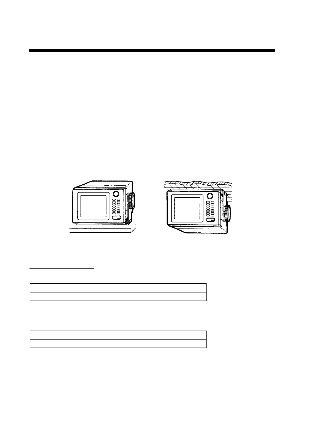
2. DISPLAY UNIT
The dis play unit can be installed with either of four methods as shown below. Refer to the
outline dr awing page D-2, D-3, and D-4.
• Locate the unit aw ay from exhaust pip es and vents.
• The mounting location should be well ventilated.
• Mount the unit where shock and vibration are minimal.
• Keep the display u ni t away el ectromagneti c fi el d g en er ati n g eq ui pm e nt such as motor,
generator.
• Allow sufficient maintenance space and a sufficient slack in cables for maintenance and
repair.
• If vibration is a problem, tilt the display unit so it contacts the vibration absorbers attached to
the inside of the hanger (t ilted within 5 °).
Table Top and Overhead Mounting
T ABLE TOP OVERHEAD
Display unit mounting methods
Flush mounting type F
An optional flush mount kit type F is required. For details, see out line drawing page D-2.
Name Type Code No.
Flush Mount Kit F OP20-25 004-393-280
Flush mounting type S
An optional flush mount kit type S is required. For details, see outline drawing page D-3.
Name Type Code No.
Flush Mount Kit S OP20-24 004-393-000
2
Page 6

3. ANTENNA UNIT
Mounting
Install the antenna unit referring to the ins tallation diagram on page D-4. When selec ting a
mounting l oc ation for the antenna unit, keep in mind the following points.
• Selec t a location out of the radar beam. The radar beam will obstruct or prevent re ception
of the GPS satellite sign al.
• Be sure the location offer s a clean line-of-sight to satellite. Objects within line-of-sight to
a satellite, for example, a mast or funnel, blo c k recep tion and cause prolonged acquiring time
or in terruption of positi on fix.
• Mount the unit as high as possible. Mounting the antenna as high as possible keeps it free
of water spray , wh ich c an int ercept reception of GPS satellite signal, if water spray is frozen.
• The antenna unit GPA-018S must be grounded. Connect gr ou nd wi re of 1.25 sq or larger
(local supply) between unit and a stainless steel screw fastened to the mast.
Extending Antenna Cable Length
The standar d c able is 15m long. 30m and 50m long extension cable sets are optionally
available. See page 4.
!Extension cable line-up
Fabricat e the end of antenna cable and attach the coax ial connector. Details are shown
on next page.
Antenna Unit
GPA-019S
GPA-018S GPA-017S
20cm
1 m
Conversion
Cable Assy.
Antenna Cable
30 m or 50 m 1 m
Fabricate locally. (See the next page.)
Extension Cable Line-up
: Connector
To display unit
!Waterproofing the connector
Wrap connector with vulcanizing tape and then vi nyl tape. Bind the tape end with
cable-tie.
How to waterproof the antenna
3
Page 7
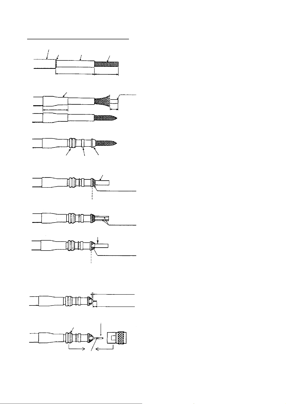
3. ANT ENNA UNIT
How to attach t he N-P-8DFB connector
Outer Sheath
Armor
Inner Sheath Shield
50
30
Remove outer sheath and armor by the dimensions
shown left.
Expose inner sheath and shield by the dimensions
shown left.
Cover with heat-shrink tubing and heat.
30
Clamp
Nut
Gasket
(reddish
brown)
Trim shield here.
Insulator
10
Clamp
Aluminum Foil
Cut off insulator and core by 10mm.
Twist shield end.
Clip on clamp nut, gasket and clamp as shown left.
Fold back shield over clamp and trim.
Cut aluminum foil at four places, 90° from one
another.
4
Fold back aluminum foil onto shield and trim.
Trim aluminum
tape foil here.
Clamp Nut
Solder through
the hole.
1
5
Pin
Shell
Expose the insulator by 1mm.
Expose the core by 5mm.
Slip the pin onto the conductor. Solder them together
through the hole on the pin.
Insert the pin into the shell. Screw the clamp nut into
the shell.
(Tighten by turning the clamp nut. Do not tighten by
turning the shell.)
Page 8
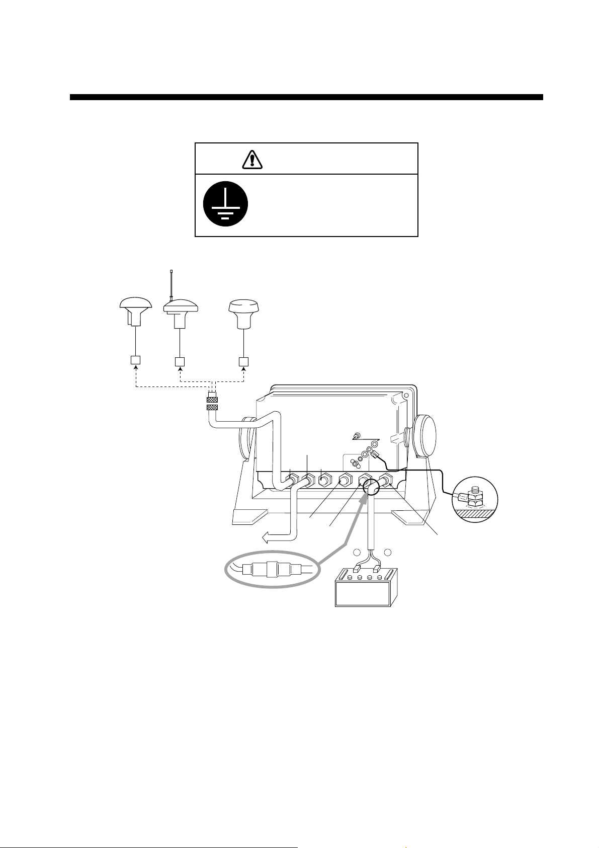
4. WIRING
The figure below shows the connecti on of cables on rear of dis play unit.
CAUTION
Ground the receiver to
prevent loss of sensitivity
and mutual interference.
Antenna Unit
GPA-019S
20cm
GPA-018S GPA-017S
External Equipment
Rear of Display Unit
DATA1
ANT
DATA2
DATA3
DATA4
–
Black Red
Ground
INPUT
+
10.2~31.2VDC
FUSE 2A
Connection of c ables on display unit
5
Page 9
4. WIRING
Grounding
The dis play unit contains s everal CPUs. While they are operating, they radiate noise, which
can interf er e with other radi o equipment. Groun d the unit as follows to prevent it.
•
The groundi ng wire should be 1.25sq or larger.
•
The groundi ng wire should be as s hor t as possible.
External Equipment
The DATA 1, DATA2, and DATA 3 por ts are used to connect an ex ternal equipment such as
autopilot, remote display, navigation equipment. Refer to the interconnecti on diagram on
page S-1 for c onnection of DATA1, DATA2 and DATA 3 port. The DATA 4 por t is used to
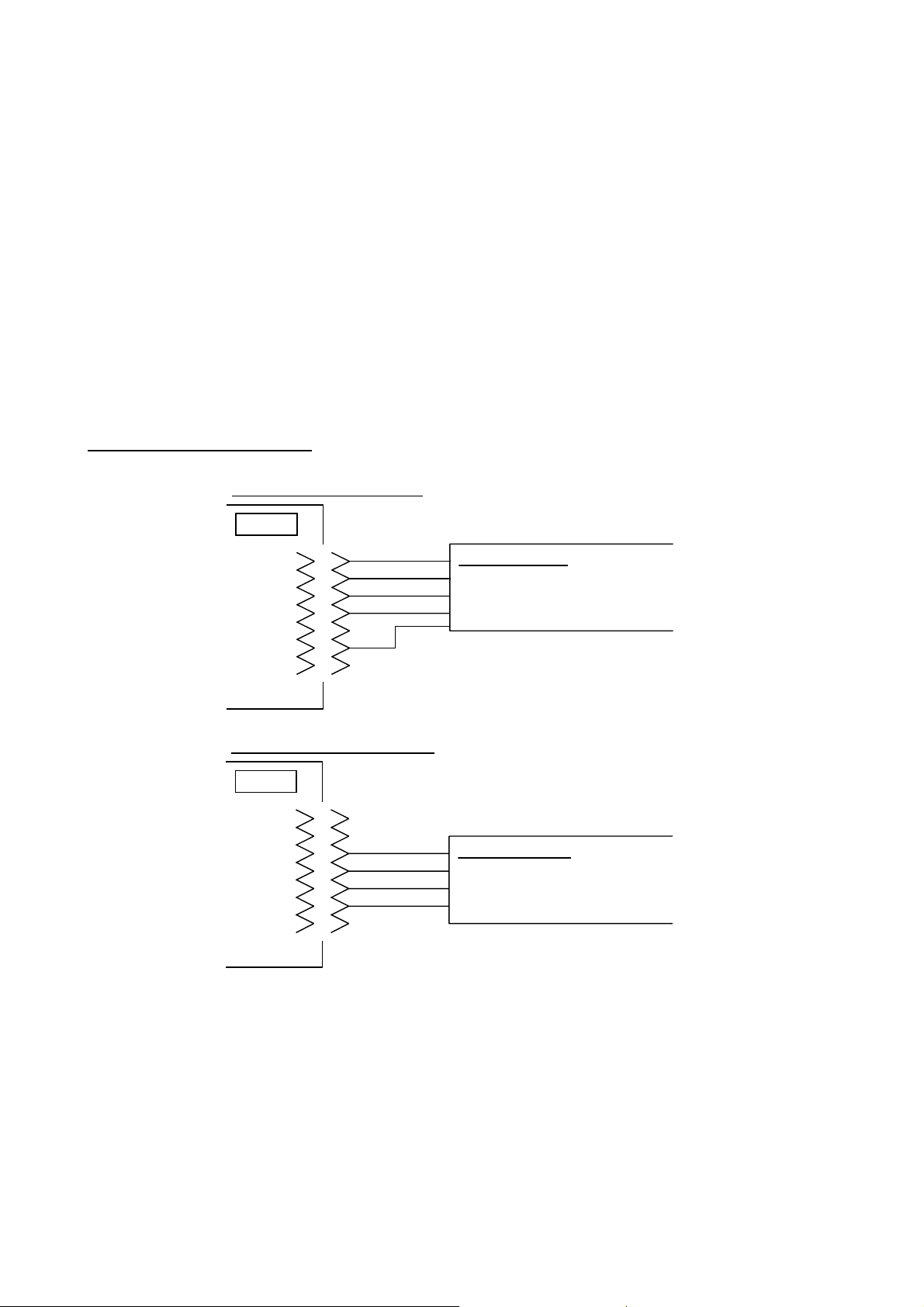
connect NMEA equipment, IBM-PC or DGPS beac on r eceiver as fol lows;
Connection of DATA4 port
In case of RS-422 Level
DATA4
TD-A
TD-B
RD-A
RD-B
S·G
1
2
3
4
5
6
7
In case of RS-232C Level
DATA4
1
2
RD
NC
SD
S·G
3
4
5
6
7
RS-422 level
IBM PC
Beacon Receiver
NMEA equipment
RS-232C level
IBM PC
Beacon Receiver
NMEA equipment
NOTE: See page 15 for selection of input/output signal.
6
Page 10
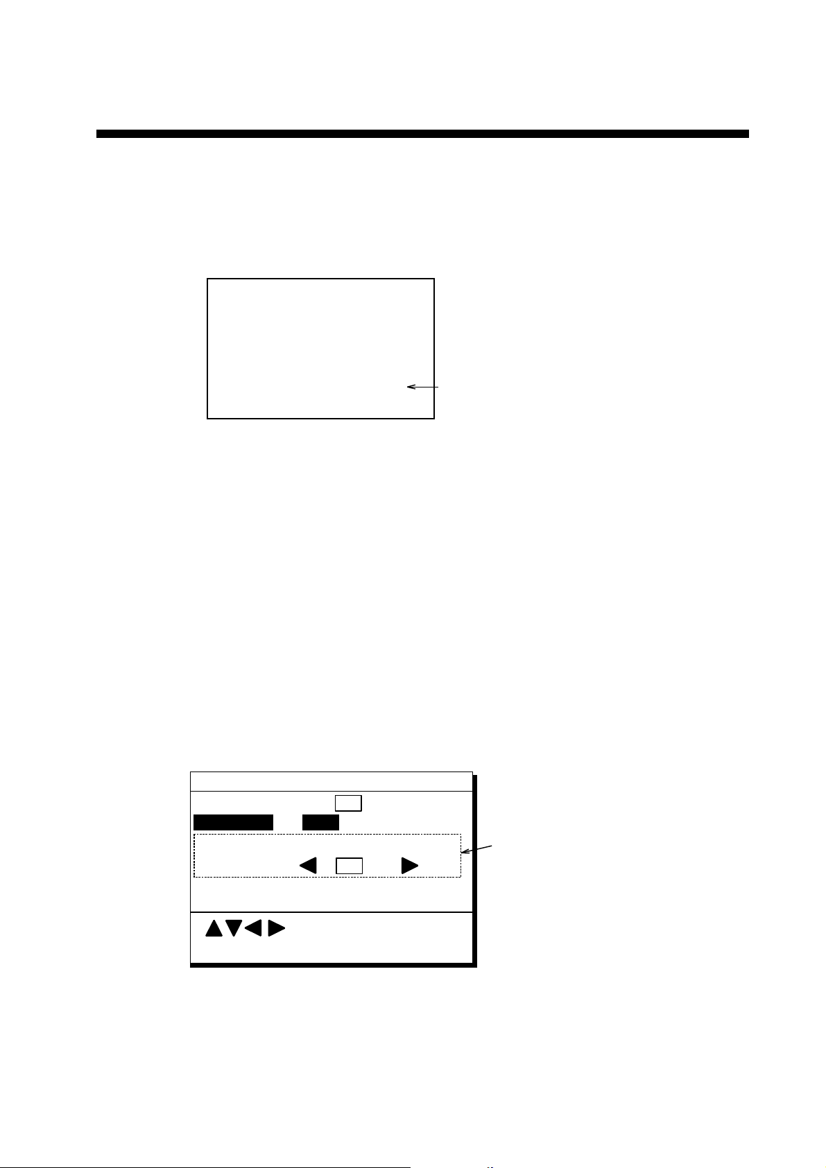
5. INITIAL SETTINGS
Checking Operation
1. Turn on the GP-80.
2. Confirm that "OK" and "BEACON RCVR INSTALLED" are display on the self-t est
display.
PROGRAM MEMORY =OK
SRAM =OK
Internal Battery
=OK
BEACON RCVR INSTALLED
DATA #3: LOG PULSE OUTPUT
Self-test display at equipment start up
3. At the GP-80, press [MENU ESC], [8] and [1]. Confirm t hat "BEACON OK" is displayed.
Confirm that "BEACON RCVR
INSTALLED" is displayed when
DGPS function is provided.
DGPS Setup
The default setting is " manual".
Automatic DGPS setup
The GR-800 c an automatical ly select optimum refer ence station by feeding it position data.
If it takes mor e than 5 minutes to fix DGPS position at the automatic m ode, switch to
manual mode. Use at manual mode when a external beacon receiver has no automatic
function of station sel ection.
1. Press [MENU ES C], [9] and [7] to di s play the DGPS SETUP m enu.
DGPS SETUP
DGPS MODE
Ref. Station Auto Man(ID= )___
Freq. 288.0kHz
Baud Rate 200 bps
On Off
These items appear when
"MAIN" is selected.
2. Press
3. Press
4. Press
:Select
ENT: Enter MENU: Escape
DGPS SETUP menu
!
or " to select DGPS MODE and press # to select On.
!
or " to select Ref. Station.
#
to select Auto.
7
Page 11

5. INITIAL SETTINGS
5. Press the [NU/CU ENT] key.
6. Press the [ME NU E S C] key.
Manual DGPS setup
Enter four digit ID number, f r equenc y and baud rate of station, ref er r ing to the DGPS li s t in
the GP-80 operator's manual .
1. Press [MENU ES C] [9] and [7] to display the DGPS SETUP menu.
!
2. Press
3. Press
4. Press
5. Enter four digi t ID number. You can clear an entry by the [CLEAR] key. If the number
entered i s invalid, the buzzer s ounds and the message " INVALID ID" appears on the
display for three seconds.
If there is no ID number, press the [NU/CU ENT] key.
6. Press the [NU/CU/ E NT] key.
7. Enter frequency in four digit s ( 283.5 kHz to 325.0 kHz).
8. Press the [NU/CU ENT] key. "Band Rat e" appears in revers e video.
9. Press
10. Press the [MENU E S C] key.
or " to select DGPS MODE and press # to select On.
!
or " to select Ref. Station.
$
to select Man.
#
or $ to select band r ate; 25, 50, 100 or 200bps.
DGPS Operation checking
1. Press [MENU ES C] and [7].
2. Press [
] several times to display the following.
8
Page 12
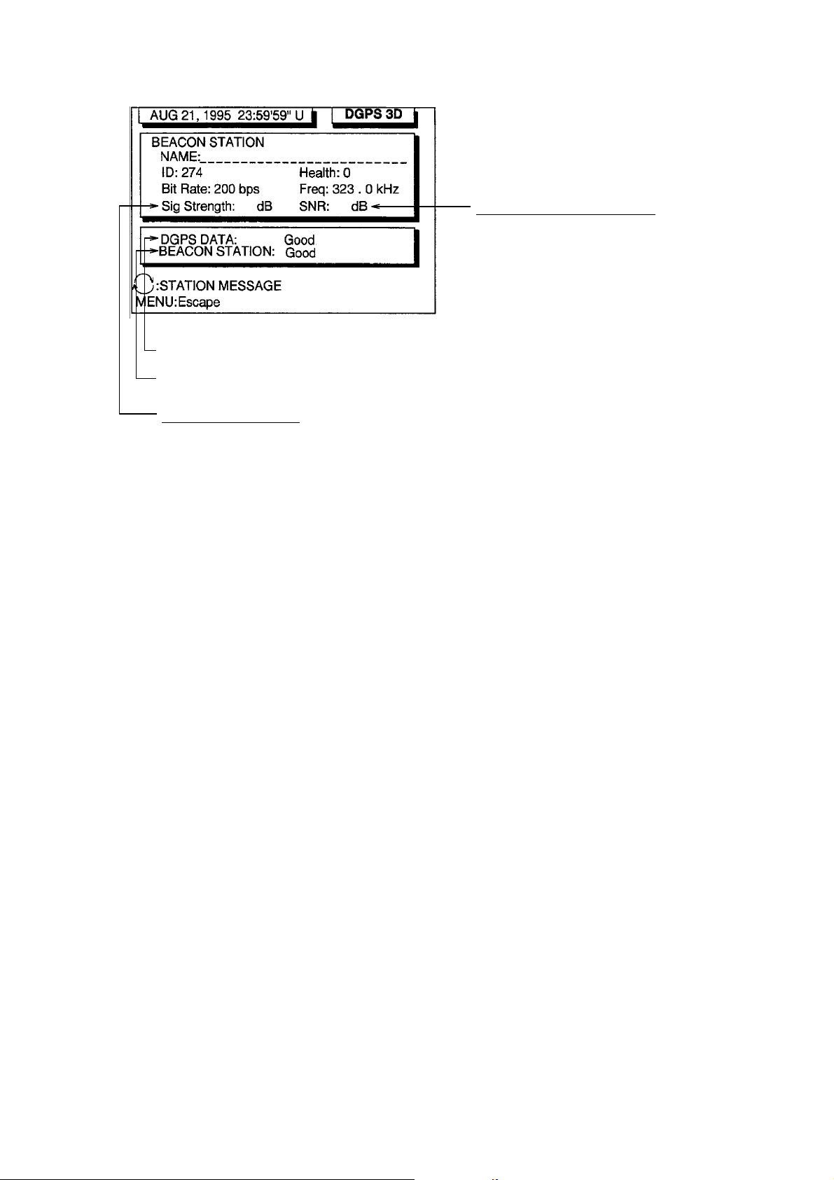
5. INITIAL SETTINGS
83 21
Beacon signal status
Reference station status
DGPS signal strength
This value is between 1
and 84. The higher the
value, the stronger the
signal. If a noise appears
at reception band width,
the value becomes bigger.
Input/Output Setting
Error rate of connection data
This value is between 1 to 22. The higher
the value, the better the reception of
beacon signal. When this value is less
than 20, the error is included in the
correction data. In this time, position
fixing is done by using past position data.
When the ship is in the service area of a
beacon station, this value should be 21 or
22. If not, check as follows.
• Check the grounding.
• Check the radar beam interference.
• Check the noise of power generator of
the ship.
The GP- 80 c an output navigation information to ex ternal equipment . For example, i t can
output position data to a radar or ec ho sounder for di s play on their display screen. You can
convert a Lor an P lotter to a GPS P lotter with posi tion data from the GP-80.
Before selec ting data to outp ut, confirm w hat data the external equipment requires. O utput
necessary data only. Out putting unnecessary data can cause receiving problems at the
external equipment.
Talker
All data tr ans m itted by marine electronics equipment is prefixed with a two character code
which t ells external equipm ent what equipment is transmitting data. This two character code
is called the talker. The GP-80 contains the t alkers GP, LC and DE.
Because GP S is a relatively new s ystem some early m odel equipment do not recognize the
GP talk er nam e. In this case transmit data using a con ventional talker, one the equipment
recogniz es , such as Loran C.
9
Page 13

5. INITIAL SETTINGS
Data format and data output availability
Outpu t data sentence of IEC 61162- 1 and NMEA 0183 Ver. 1.5/V2.0.
AAM: Waypoint arrival alar m
APB: Autopilot sentence B
magnitude of c r os s track error, direction to steer , arrival alarm, bear ing to waypoi nt
("Heading to steer to destination waypoint data" not used)
BOD: Bearing-origin to destinat ion
BWC: Bearing and distance to waypoi nt-great circle
BWR: Bearing and distance to waypoi nt-rhumb line
BWW: Bearing-waypoint to waypoint
DTM: Datum reference
GGA: Global positioning system (G P S ) fix data
time of fix, latitude, l ongitude, quality indicator, number of sat ellites in use, DOP,
altitude, geoidal separation
("age of dgps data" and "diff er ential reference station ID" not us ed)
GLL: Geographic position-latitude/longitude
GNS: GNSS fix data
RMB: Rec om mended mini mum navigation inf or m ation cross tr ac k er r or , direction t o s teer,
origin and destination waypoint ID, destination waypoint latitude and longit ude,
range and bearing of destination waypoint , destination clos ing velocity , arrival
alarm
RMC: Recommended minimum specific GPS/TRA NSIT data
UTC of position fix, latit ude and longitude, ground speed and course, date,
magneti c variation
RTE: Routes
VTG: Course over ground and ground speed
WCV: Waypoint closure vel oc ity
WNC: Distance-w aypoint to waypoi nt-great circle
WPL: Waypoint location
XTE: Cross-track er ror, measured
ZDA: Time and date
ZTG: UTC and ti m e to destination waypoint
Also, f ollowing NMEA 0183 Ver . 1.5 sentences are out put.
APA: Autopilot sentence "A"
magnitude of c r os s track error, direction to steer , arrival alarm, bear ing origin to
destination.
WNR: Distance-waypoint to waypoint-rhumb line
ZLZ: Time of day
UTC, loc al time, lo c al zone
10
Page 14

5. INITIAL SETTINGS
Input data sentence of NMEA 0183 Ver. 1.5/2.0
Checksum is checked if att ac hed, and if any errors are found, the sentence becomes invalid.
Talker I D is not distinguished.
DBT: Depth below transducer
$--DBT, 1234.5, f, 1234.5, M, 1234.5, F*12<CR><LF>
a b c d e f g
a, b: Water depth, f eet
c, d: Water depth, m
e, f: Water d epth, fathoms
g: checksum
DPT: Depth
$--DPT, 1234.5, 1234.5*23< CR> <LF>
a b c
a: Water depth relative to the transducer, meters
b: Offset from transducer, meters. ..not used
c: checksum
MTW: Water temperature
$--MTW, 23.4, C*34< CR><LF>
a b c
a, b: Temper ature, degrees C
c: checksum
TLL: Target latitude and longit ude
$--TLL, 00, 3445.678, N, 1352 1.234, E, abcd, 121530, T, R*A5<CR><LF>
h
a b c d e f g
a: Target number...not used
b, c: Latitude
d, e: Longitude
f: Target name...not used
g: UTC...not used
h: Target status...not used
i: Reference target...not used
j: checksum
FURUNO propr ietary sentenc es
i j
11
Page 15

5. INITIAL SETTINGS
AGFPA: A utopilot information from FURUNO autopilot equipments
Port Input Output
DATA1
DATA2
NMEA 0183
Ver. 1.5 /2.0
AGFPA , DBT, DPT,
MTW, TLL
(Selected by menu)
IEC 61162-1/NMEA 0183 Ver.1.5/
Ver.2.0
AAM, APA, APB, BOD, BWC, BWR,
BWW, GGA, GLL, GNS, RMB, RMC,
VTG, WCV, WNC, WNR, WPL, XTE,
ZDA, ZLZ, ZTG, Rnn, RTE, DTM
Same as the dat a output form “DATA1”
IEC 61162-1/NMEA 0183 Ver.1.5/
Ver.2.0
AAM, APA, APB, BOD, BWC, BWR,
BWW, GGA, GLL, GNS, RMB, RMC,
VTG, WCV, WNC, WNR, WPL, XTE,
ZDA, ZLZ, ZTG, Rnn, RTE, DTM
LOG PULSE DATA3 External MOB
General data DATA4 DGPS or general data
General data
1) Input of buoy information
Floppy disk stored buoy inf or m ation is supplied f r om P C c onnected at DAT A 4 port.
2) Input of waypoint data
Connect YEOMAN equipment t o DA TA4 port.
3) Input and output of waypoint / rout e data
Rate of operation
The TX r ate of operation is the perc entage of data out put in one second, and i t appears on
the screen. If short intervals ar e as s igned to many sentences, the rate of operation
increases as illustrated below
A rate of operat ion exceeding 100% is impractical. For bett er per formance, the rate of
operati on s hould be less than 90%.
When the external equipment c annot display c or rec t data input from the GP-80, the rate of
operati on s hould be lowered.
For example, set a rate of operation less than 60% for the Temperature Indicator TI - 20.
TX TX TX
12
Page 16

5. INITIAL SETTINGS
DATA 1 output sett in g
1) Press [MENU] [9] and [3]. The DAT A 1, 3 O UTPUT SETUP menu appear s .
DATA 1, 3 OUTPUT SETUP
Data Fmt. V1.5 IECV2.0
Talker ID GP LC DE
Output Data (00-90 sec)84%
1. AAM:00 APA:00 APB:01 BOD:00
2. BWC:00 BWW:00 GGA:01 GLL:00
3. RMB:01 RMC:01 VTG:01 WCV:00
4. WINC:00 WPL:00 XTE:00 ZDA:01
5. GNS:00 ZTG:000 Rnn:00 RTE:00
DATA3. Log Pulse
200ppm
400ppm
ENT : Enter
Settings shown here are default settings.
This line appears only when LOG is
selected by internal jumper wires.
MENU : Escape
Figure 5-1 DATA 1, 3 OUTPUT SETUP menu
2) Press
3) Press
!
or " to select Data Fmt.
#
or $ to select V1.5, V2.0 or IEC.
4) Press the [ENT ] key. Talker ID appears in reverse video.
#
5) Press
or $ to select GP, LC or DE.
6) Press the [ENT ] key.
7) Enter Tx interval for each output data sentence in line 1. Tx interval is avai lable in 00,
01, 02, 03, 04, 05, 06, 10, 15, 20, 30, 60, and 90 sec.
8) Press the [ENT ] key.
9) Enter Tx interval for each output data sentence in lines 2 through 5. Press the [ENT] key
after setting each line.
In great c ircle calculation, BWC and WNC are out put but BWR and WNR are not . In rhumb
line navigat ion, BWR and WNR are output but BWC and WNC are not.
The tot al data output are shown by percentage on the third line.
For best results the total output should be less than 90%; lengthen the Tx interval of less
important data to make the total output less than 90%.
13
Page 17

5. INITIAL SETTINGS
DATA 2 output setting
1) Press [MENU] [9] and [4]. The DAT A 2 OUT P UT SETUP menu appears.
DATA2 OUTPUT SETUP
NMEA Fmt.
Talker ID GP LC DE
Output Data (00-90 sec)80%
1. AAM:00 APA:00 APB:04 BOD:00
2. BWC:00 BWR:00 BWW:00 GGA:00
3. GLL:01 RMB:01 RMC:01 VTG:01
4. WCV:00 WNC:00 WNR:00 WPL:10
5. XTE:00 ZDA:01 GNS:00 ZTG:00
: Select
ENT : Enter
183/V1.5
MENU : Escape
183/V2.0
Setting shown here are default settings.
Figure 5-2 DATA 2 OUTPUT SETUP menu
2) Follow the procedure for setting DA TA 1 output.
DATA 3 output sett in g
The DATA 3 c an output NMEA 0183 (V1.5/V2.0) /IE C 61162- 1 data or log pulse by
selecting inner jumper wire. For NMEA 0183 (V1.5/V2.0) /IEC 61162-1, the same signal of
DATA 1 is output from DATA 3.
Selection of NMEA0183 or log pulse
Output data
NAV board
JP4 (2 pcs.) ON OFF
JP5 (3 pcs.) OF F ON
Rate of log pulse output
NMEA 0183 (V1.5/
V2.0)/IEC 61162-1
Log pulse
500 mA Max.
50 VDC
Procedure for setting of log pulse rate
1) Press [MENU] [9] and [3].
!
2) Press
3) Press
or " to select DA TA 3. Log Pulse.
#
or $ to select log pulse for external equipment; 200ppm or 400ppm.
4) Press the [ENT ] key.
5) Press the [ESC] key.
14
Page 18

Setting DATA 4 to Data Output
1) Press [MENU] [9] and [5]. The DAT A 4 I/ O SETUP m enu appears.
DATA 4 I/O SETUP 1/2
DATA 4. Level RS232C RS422
Data Out Com. DGPS
To Next Page
: Select
ENT : Enter MENU : Escape
Appears only when external
2) Press
3) Press
!
or " to select Level.
#
or $ to select level of external equipment; RS232C or RS422.
4) Press the [ENT ] key.
#
5) Press
6) Press
or $ to select Out.
"
to select to Next Page. The DATA 4 I/O SETUP menu appears .
DGPS receiver is used.
Figure 5-3 DATA 4 I/O SETUP m enu
5. INITIAL SETTINGS
DATA 4 I/O SETUP <Out> 2/2
To Previous Page
Data Fmt. V1.5 V2.0 IEC
Talker ID GP LC DE
Output Data (00-90 sec) 84%
1. AAM:00 APA:00 APB:01 BOD:00
2. BWC:00 BWW:00 GGA:01 GLL:00
3. RMB:01 RMC:01 VTG:01 WCV:00
4. WNC:00 WPL:00 XTE:00 ZDA:01
5. GNS:00 ZTG:00 Rnn:00 RTE:00
ENT : Enter
MENU : Escape
Figure 5-4 DATA 4 I/O SETUP m enu
7) Follow "DATA 1 output setting" f r om s tep 2.
15
Page 19

5. INITIAL SETTINGS
Setting DATA 4 to “COM.” (general data)
Waypoints and Routes data can be received from a per s onal computer, t hr ough the DATA
4 port.
1) Press [MENU] [9] and [5].
!
2) Press
3) Press
4) Press the [ENT ] key.
5) Press
6) Press
or " to select Level.
#
or $ to select level of personal c om puter; RS232C or RS422.
$
to select Com.
"
to select To Next Page. The DATA 4 I/O SETUP menu appears .
DATA 4 I/O SETUP <Com.> 2/2
To Previous Page
Baud Rate 9600 bps
L WPT
Load Data
Command Stop Start
Save Data WPT/RTE
Command Stop Start
L.House*
WPT/RTE
: Select
ENT : Enter
MENU : Escape
*: Not used.
Figure 5-5 DAT A 4 I/O SET UP menu
7) Press
8) Press
!
or " to select B aud Rate.
#
or $ to select baud r ate; 4800bps, 9600bps, or 19200bps.
9) Press the [ENT ] key.
#
10) Press
11) Press
or $ to select WPT/RTE.
"
to select Com m and. Stop, on the sam e line as Command, appears in revers e
video.
$
12) Press
to select S tart. The message shown in Figure 5-6 app ear s .
Loading erases current data
and stops Route navigation
Are you sure to load?
ENT: Yes MENU: No
Figure 5-6
13) Press the [ENT] key. The mes s age s hown in Figure 5-7 appears while data is being
loaded.
16
Now loading
Waypoint/Route data !
MENU: Stop
Figure 5-7
Page 20

5. INITIAL SETTINGS
14) Output data from the computer. When data is loaded, the cursor shifts to Stop.
15) Press the [ESC] key.
Setting DATA 4 to DGPS
An external DGPS receiver can b e c onnected to the DA TA 4 port.
Follow the procedure below to setup the GP-80 according to the speci fications of the DG P S
receiver.
1) Press [MENU] [9] and [5].
!
2) Press
3) Press
4) Press the [ENT ] key.
5) Press
6) Press
or " to select Level.
#
or $ to select level; RS232C or RS422.
#
or $ to select DGPS.
"
to select To Next Page.
DATA 4 I/O SETUP "DGPS" 2/2
To previous Page
First Bit
Parity
Stop Bit
Baud Rate
MSB LSB
EVEN ODD NONE
12
4800 9600
Figure 5-8 DATA 4 I/O SETUP " DGPS" 2/2 menu
7) Press
8) Press
9) Press
10) Press
11) Press
12) Press
13) Press
14) Press
!
or " to select First Bit.
#
or $ select first bit; MSB or LSB.
"
to select Parity Bit.
#
or $ to select parity bit; EVEN, ODD or NONE.
"
to select Stop Bit.
#
or $ to select s top bit; 1 or 2.
"
to select B aud Rate.
#
or $ to select baud r ate; 4800 or 9600.
15) Press the [ENT] key.
16) Press the [ESC] key.
: Select
ENT: Enter MENU: Escape
17
Page 21

5. INITIAL SETTINGS
Interface Documentation
"DATA1" Port
! IEC 61162-1/NMEA 0183 Ver. 1.5 Output
•
Output Schem atic Diagram (Talker)
DATA 1
TD-A
TD-B
20P8147
J5
1
2
6
MJ-A6SRMD
FL14
FL13
6
7
U35
SN75ALS172
8
• Outp ut Drive Capability
Max. 10mA
• IEC 61162-1 output subject to the standard of IEC 61162-1 First edition 1995-11.
• Output Sentence is described on page 8 and 9. Each sentence is output at the interval
entered.
! NMEA 0183 Input
• Input Schematic Diagram (Listener)
20P8147
DATA 1
RD-H
RD-C
MJ-A6SRMD
J5
1
2
3
4
5
6
FL12
FL11
• Load Requirements
Isolation: opto coupler
Input Impedance: 470
Max. Voltage:
±
15V
Threshold: 3mA (In case of FURUNO device talker c onnec tion)
• Input Sentenc e is desc r i b e d on pa ge 11 .
+5V
R77
470
CR13
1SS226
1
PC-400
3
U17
R64
2.2K
4
5
Ω
18
Page 22

"DATA2" Port
! IEC 61162-1/NMEA 0183 Ver. 1.5/Ver. 2.0 Output
• Output Schematic Diagram (Talker)
20P8147
DATA2
TD-A
MJ-A6SRMD
J7
1
FL9
5. INITIAL SETTINGS
16
18
TD-B
2
3
4
5
6
FL10
17
U35
SN75ALS172
• Outp ut Drive Capability
Max. 10mA
• IEC 61162-1 output is subject to the standard IEC 61162-1 First edition 1995-11.
• Output Sentence is described on page 8 and 9. Each sentence is output at the interval
entered.
! NMEA 0183 Input
• Input Schematic Diagram (Listener)
20P8147
DATA2
RD-H
RD-C
MJ-A6SRMD
J7
1
2
3
4
5
6
FL7
FL8
R76
470
CR14
1SS226
1
PC-400
3
U28
+5V
R63
2.2K
4
5
• Load Requirements
Isolation: opto coupler
Input Impedance: 470
Max. Voltage:
±
15V
Ω
Threshold: 3mA (In case of FURUNO device talker c onnec tion)
• Input Sentenc e is des cr i b e d on page 8 and 9.
19
Page 23

5. INITIAL SETTINGS
"DATA3" Port
• The output signal of this port is changed by jumper JP4 and JP5 between data out (IEC
61162-1/NMEA 0183 Ver.
1.5/Ver. 2.0) and log pulse.
• In case of data out, the same data of DATA1 port (#1 & #2) is output.
• Output Schematic Diagram (Talker)
DATA3
TD-A
TD-B
20P8147
MJ-A6SRMD
J6
1
2
3
4
5
6
FL6
FL5
1
3
2
4
JP4
14
13
U35
SN75ALS172
12
• Outp ut Drive Capability
Max. 10mA
"DATA4" Port
IN/O UT signal is selected by the menu among the outp ut of IEC 61162-1, NMEA 0183 Ver.
1.5/Ver. 2.0, PC output/i nput and DGPS signal. A lso, to select DG P S s ignal, jumper JP3 is
required to connect "extern al DGPS receiver."
RS-232C or RS-422 level can be s elected by the menu.
In case of output of IEC 61162-1, NMEA 0183 Ver. 1.5/Ver. 2.0,
• Data fo r mat can be selected by the menu between IE C 61162-1 and NMEA 0183 Ver.
1.5/Ver. 2.0.
• Output sentence is describe d on pa ge 8 and 9.
• Each sentence is output at the interval entered.
20
Page 24

6. OPTIONAL DGPS
Beacon Receiver Set GR-80
GP-80
DATA4
RS-422*
NP Board
JP3
Open
TD-A
TD-B
RD-A
RD-B
GND
1
2
3
4
5
6
7
WHT
BLK
YEL
GRN
BLU
4
P
3
2
P
1
7
DATA
RD-A
RD-B
TD-A
TD-B
GND
GR-80
RS-422
Whip
Antenna
Preamp unit (with
15 m cable)
* This connection is required for L/L Auto mode of GR-80.
When the GP-80 is connected with Beacon Receiver G R- 80, do the setting as follows .
Signal level RS-422 *1
First Bit LSB
Parity Bit NONE
St op B it 1
Communic ation Speed 4800 or 9600 *1
*1: Coinci de with the setting of the Beacon Receiver GR-80.
1) Press [MENU ESC] [9] and [5].
!
2) Press
3) Press
or " to select Level.
#
or $ to select level; RS232C or RS422.
4) Press the [NU/CU/ENT] key.
#
5) Press
6) Press
or $ to select DGPS.
"
to select To Next Page.
DATA 4 I/O SETUP "DGPS" 2/2
To previous Page
First Bit
Parity
Stop Bit
Baud Rate
MSB LSB
EVEN ODD NONE
12
4800 9600
: Select
ENT: Enter MENU: Escape
DATA 4 I/O SETUP "DGPS" 2/2 menu
21
Page 25

6. OPTIONAL DGPS
7) Press ! or " to select First Bit.
8) Press
9) Press
10) Press
11) Press
12) Press
13) Press
14) Press
#
or $ to select first bit; MSB or LSB.
"
to select Parity.
#
or $ to select parity bit; EVEN, ODD or NONE.
"
to select Stop Bit.
#
or $ to select s top bit; 1 or 2.
"
to select B and Rate.
#
or $ to select band r ate; 4800 or 9600.
15) Press the [MENU ESC] key.
22
Page 26

PACKING LIST
C4374‑Z01‑H
A - 1
PACKING LIST
PACKING LISTPACKING LIST
GP-80-**-0/0-HK
GP-80-**-0/0-HK
GP-80-**-0/0-HKGP-80-**-0/0-HK
20AM-X-9851 -10
1/1
N A M E
ユニット
ユニット UNIT
ユニットユニット
空中線部
ANTENNA UNIT
空中線部
ANTENNA UNIT
空中線部
ANTENNA UNIT
受信演算部
DISPLAY UNIT
予備品
予備品 SPARE PARTS
予備品予備品
ヒューズ
FUSE
工事材料
工事材料 INSTALLATION MATERIALS
工事材料工事材料
+トラスタッピンネジ
UNIT
UNITUNIT
SPARE PARTS SP20-00500
SPARE PARTSSPARE PARTS
INSTALLATION MATERIALS CP20-01101
INSTALLATION MATERIALSINSTALLATION MATERIALS
O U T L I N E
DESCRIPTION/CODE №
GPA-017S
000-040-537
GPA-018S
000-041-462
GPA-019S
000-142-545
GPR-020-E-N
000-040-542
FGBO-A 2A AC125V
000-549-062
5X20 SUS304 1シュ
**
**
SP20-00500
SP20-00500SP20-00500
CP20-01101
CP20-01101CP20-01101
Q'TY
1
(*1)
1
(*1)
1
(*1)
1
3
+TAPPING SCREW
その他工材
その他工材 OTHER INSTALLATION MATERIALS
その他工材その他工材
ケーブル組品MJ
CABLE ASSY.
ケーブル組品MJ
POWER CABLE
ケーブル組品
ANTENNA CABLE ASSY.
1.コード末尾に[**]の付いたユニットは代表の型式/コードを表示しています。
DOUBLE ASTERISK DENOTES COMMONLY USED EQUIPMENT.
2.(*1)の空中線部は仕様により決定されます。
ANTENNA UNIT HAS BEEN DETERMINED BY SPECIFICATION.
OTHER INSTALLATION MATERIALS
OTHER INSTALLATION MATERIALSOTHER INSTALLATION MATERIALS
4
000-802-081
MJ-A6SPF0003-050
1
000-117-603
MJ-A2SPF0014-030
(VV0.75X2C *3M*)
1
000-128-522
TNC-PS-3D-15 20S0216
1
000-133-670
(略図の寸法は、参考値です。 DIMENSIONS IN DRAWING FOR REFERENCE ONLY.)
(略図の寸法は、参考値です。 DIMENSIONS IN DRAWING FOR REFERENCE ONLY.)
(略図の寸法は、参考値です。 DIMENSIONS IN DRAWING FOR REFERENCE ONLY.)(略図の寸法は、参考値です。 DIMENSIONS IN DRAWING FOR REFERENCE ONLY.)
Page 27

1
C4374‑Z07‑F
A - 2
1/1
2
1
1
1
20AM-X-9852-10
20-007-3011-2
NAME OUTLINE Q'TYDESCRIPTION/CODE №
パイプ
100-183-262
PIPE
NO.6348 SUS303
パーカークランプ
000-805-906
OTHER INSTALLATION MATERIALSOTHER INSTALLATION MATERIALS
OTHER INSTALLATION MATERIALS
その他工材
その他工材その他工材
HOSE CLAMP
その他工材 OTHER INSTALLATION MATERIALS
MJ-A6SPF0003-050
ケーブル組品MJ
000-117-603
MJ-A2SPF0014-030
(VV0.75X2C *3M*)
CABLE ASSY.
ケーブル組品MJ
000-128-522
TNC-PS-3D-15
20S0216
POWER CABLE
ケーブル組品
000-133-670
ANTENNA CABLE ASSY.
GP-80-**-1/1-HK
GP-80-**-1/1-HKGP-80-**-1/1-HK
GP-80-**-1/1-HK
UNITUNIT
UNIT
GPA-017S
1
1
(*1)
**
000-040-537
GPA-018S
(*1)
000-041-462
GPA-019S
1
(*1)
000-142-545
GPR-020-E-N
1
3
SP20-00500SP20-00500
SP20-00500
**
000-040-542
FGBO-A 2A AC125V
SPARE PARTSSPARE PARTS
SPARE PARTS SP20-00500
000-549-062
4
CP20-01101CP20-01101
CP20-01101
5X20 SUS304 1シュ
INSTALLATION MATERIALSINSTALLATION MATERIALS
INSTALLATION MATERIALS CP20-01101
000-802-081
CP20-01111CP20-01111
CP20-01111
INSTALLATION MATERIALSINSTALLATION MATERIALS
INSTALLATION MATERIALS CP20-01111
1
20-007-3012-1
100-183-271
NAME OUTLINE Q'TYDESCRIPTION/CODE №
ユニット
ユニットユニット
ユニット UNIT
PACKING LIST
PACKING LISTPACKING LIST
PACKING LIST
空中線部
空中線部
ANTENNA UNIT
ANTENNA UNIT
空中線部
ANTENNA UNIT
受信演算部
DISPLAY UNIT
予備品
予備品予備品
予備品 SPARE PARTS
ヒューズ
FUSE
工事材料
工事材料工事材料
工事材料 INSTALLATION MATERIALS
+トラスタッピンネジ
+TAPPING SCREW
工事材料
工事材料工事材料
工事材料 INSTALLATION MATERIALS
取付補助金具
INSTALLING SPACER
(略図の寸法は、参考値です。 DIMENSIONS IN DRAWING FOR REFERENCE ONLY.)
(略図の寸法は、参考値です。 DIMENSIONS IN DRAWING FOR REFERENCE ONLY.)(略図の寸法は、参考値です。 DIMENSIONS IN DRAWING FOR REFERENCE ONLY.)
1.コード末尾に[**]の付いたユニットは代表の型式/コードを表示しています。
DOUBLE ASTERISK DENOTES COMMONLY USED EQUIPMENT.
(略図の寸法は、参考値です。 DIMENSIONS IN DRAWING FOR REFERENCE ONLY.)
2.(*1)の空中線部は仕様により決定されます。
ANTENNA UNIT HAS BEEN DETERMINED BY SPECIFICATION.
Page 28

CODENO.
A - 3
CODENO.
CODENO.CODENO.
TYPE
TYPE
TYPETYPE
20AG‑X‑9404
‑1
1/1
工事材料表
工事材料表
工事材料表工事材料表
INSTALLATIONMATERIALS
番号
NO.
1
2
名 称
NAME
アンテナケーブル組品
ANTENNACABLEASSY.
ケーブル組品
CABLEASSY.
GP‑80,GP‑90,SC‑55,GP‑3500/F
GP‑1850,GP‑1650,FA‑100,GP‑1640/F
SC‑60/120,GD/GP‑280/680/380
略 図
OUTLINE
型名/規格
DESCRIPTIONS
8D‑FB‑CV*30M*
CODENO.
8D‑FB‑CV*50M*
CODENO.
000‑111‑547
000‑117‑599
数量
Q'TY
用途/備考
REMARKS
選択 TOBESELECTED
1
選択 TOBESELECTED
1
FURUNO ELECTRIC CO .,LTD.
(略図の寸法は、参考値です。 DIMENSIONSINDRAWINGFORREFERENCEONLY.)
(略図の寸法は、参考値です。 DIMENSIONSINDRAWINGFORREFERENCEONLY.)
(略図の寸法は、参考値です。 DIMENSIONSINDRAWINGFORREFERENCEONLY.)(略図の寸法は、参考値です。 DIMENSIONSINDRAWINGFORREFERENCEONLY.)
Page 29

工事材料表
A - 4
工事材料表
工事材料表工事材料表
INSTALLATIONMATERIALS
番号
NO.
1
名 称
NAME
変換ケーブル組品
CONVERTCABLEASSY.
略 図
OUTLINE
CODENO.
CODENO.
CODENO.CODENO.
TYPE
TYPE
TYPETYPE
型名/規格
DESCRIPTIONS
NJ‑TP‑3DXV‑1
CODENO.
004‑372‑420
CP20‑01701
000‑123‑809
数量
Q'TY
20AG‑X‑9405
用途/備考
2
‑1
1/1
REMARKS
ビニールテープ
2
VINYLTAPE
コネクタ(N)
3
CONNECTOR
絶縁テープ
4
SELF‑BONDINGTAPE
NO36002X19X10000
クロ エスロン
CODENO.
N‑P‑8DFB
CODENO.
Uテープ 0.5X19X5M
CODENO.
000‑835‑215
000‑111‑549
000‑800‑985
1
1
1
FURUNO ELECTRIC CO .,LTD.
(略図の寸法は、参考値です。 DIMENSIONSINDRAWINGFORREFERENCEONLY.)
(略図の寸法は、参考値です。 DIMENSIONSINDRAWINGFORREFERENCEONLY.)
(略図の寸法は、参考値です。 DIMENSIONSINDRAWINGFORREFERENCEONLY.)(略図の寸法は、参考値です。 DIMENSIONSINDRAWINGFORREFERENCEONLY.)
Page 30

Feb. 19, '03
D - 1
Page 31

Feb. 19, '03
D - 1A
Page 32

Feb. 19, '03
D - 1B
Page 33

July 22, '02
D - 1C
Page 34

Feb. 28, '03
D - 2
Page 35

Feb. 28, '03
D - 3
Page 36

Feb. 28, '03
D - 4
Page 37

RD‑A/RD‑H
Takahashi T.
Takahashi T.
Y.Hatai
YoshitoshiHata
i
電子署名者:YoshitoshiHataiDN:cn=Yos
署名は検証されていません。
S - 1
シロ WHT
TXD
RD‑B/RD‑CHC
キYEL
クロ BLK
入出力データ、センテンスについては
ミドリGRN
USING I/O DATA SENTENCES.
REFER TO INSTALLATION MANUAL FOR
装備要領書を参照のこと。
TXD
RD‑A/RD‑H
H
RD‑B/RD‑C
シロ WHT
クロ BLK
キYEL
C
ミドリGRN
(MOBスイッチ)
リモートイベントスイッチ
REMOTE EVENT SWITCH
(Man Over Board SWITCH)
RD‑A/RD‑H
RD‑B/RD‑C
キYEL
クロ BLK
ミドリGRN
シロ WHT
EXTERNAL DGPS BEACON RECEIVER OR PC.
REFER TO INSTALLATION MANUAL TO CONNECT
外部DGPSビーコン受信機またはパソコンを接続する
シロ WHT
クロ BLK
YEOMAN EQUIPMENT IS CONNECTED TO #3/#4.
場合は装備要領書を参照のこと。
アオ BLU
アカ RED
ミドリGRN
キYEL
GP‑80
TITLE
GPS航法装置
名称
相互結線図
NAME
GPS NAVIGATOR
..
.
DD
D.
TT
TD
LL
LT
,,
,L
..
.,
OO
O.
CC
CO
CC
CC
II
IC
RR
RI
TT
TR
CC
CT
EE
EC
LL
LE
EE
EL
OO
OE
NN
NO
UU
UN
RR
RU
UU
UR
INTERCONNECTION DIAGRAM
F
FF
FU
MJ‑A6SPF0003,5m,φ6 (20S0093)
*3
P
P
MJ‑A6SPFD
34
1
A
J5
DATA1
*4
受信演算部
DISPLAY UNIT
5
3
2
4
CHB
NC
TD
RD
Ver1.5
NMEA0183
IEC61162‑1/
J3
J2
GPR‑020
BEACON*2GR‑7000A
2
MJ‑A6SPF0003,5m,φ6 (20S0093)
*3
MJ‑A6SPF0011,5/10m,φ6,6P‑4P
MJ‑A6SPF0012,5/10m,φ6,6P‑6P
6
FG
RECEIVER
P
P
MJ‑A6SPFD
1
ABH
J7
DATA2
*4
J3 J1
5
3
2
4
C
NC
RD
TD
Ver1.5
NMEA0183
IEC61162‑1/
J13J11
GN‑8091
GPS BOARD
MJ‑A6SPF0003,5m,φ6 (20S0093)
*3
6
FG
DATA3
NJ‑TP‑3DXV‑1
1m, φ5.3
N‑J‑3 *3
N‑P‑8DFB
P
P
MJ‑A6SPFD
2
1
A
J6
TD
*4
IEC61162‑1/
GPS
ANT
J12
1
*3
TNC‑P‑3
6
5
3
4
CHB
NC
FG
RD
OR
MOB IN
LOG PULSE OUT
NMEA0183 Ver1.5
GND
2
MJ‑A7SPF0003,5m,φ6 (20S0241)
*3
J8
DATA4
*4
PWR
(+)
J1
1
*3
MJ‑A2SPFD
アカ RED
2A
FUSE
[RS422/RS232C]
MJ‑A7SPFD
(‑)
2
クロ BLK
P
P
5
3
2
1
4
SD
RD‑A/RD
TD‑A
TD‑B
RD‑B
*4
NMEA0183,
IEC61162‑1/
COM OR DGPS
P
6
7
FG
SG
*1
20‑013‑5007‑0
GND
IV‑1.25SQ.
kg
B1 NP 20P8188
DRAWN
T. NISHINO
Sep. 26 '03
CHECKED
APPROVED
MASS
SCALE
C4374‑C05‑ C
DWG NO.
*1GND
*3
MJ‑A2SPF0014,3m,φ6
N‑P‑8DFB
1
GPA‑017S
GPA‑018S
ANTENNA UNIT
空中線部
GPA‑019S
TNC‑P‑3 *3
TNC‑J‑3 *3
0.2m
N‑J‑3 *3
NJ‑TP‑3DXV‑1,1m,φ5.3
A
TNC‑PS‑3D‑15, 15m, φ5.3
(CP20‑01700/01710)
8D‑FB‑CV,30/50m,φ14.3
B
12/24 VDC
*2
整流器
*1
100/110/
220/230VAC,
DPYC‑1.5
RECTIFIER
1φ,50/60Hz
IV‑2SQ.
PR‑62
*1. SHIPYARD SUPPLY.
*2. OPTION
*3. FITTED AT FACTORY.
*1)造船所手配。
*2)オプション。
注記
*3)コネクタは工場にて取付済み。
*4)メニューにて選択。
NOTE
*4. SELECTABLE ON MENU.
C
 Loading...