

Page 1
COLOR GPS/PLOTTER/SOUNDER
Back
GP-7000F
Page 2

Thepaperusedinthismanual
9-52 Ashihara-cho,9-52 Ashihara-cho,
A
A
*
0
*
0
*
0
*
0
*
O
*
O
*
O
*
O
Nishinomiya 662-8580, JAPANNishinomiya 662-8580, JAPAN
Telephone :Telephone : 0798-65-21110798-65-2111
FaxFax 0798-65-42000798-65-4200
::
iselementalchlorinefree.
FURUNO Authorized Distributor/DealerFURUNO Authorized Distributor/Dealer
ll rights reserved.
ll rights reserved.
Pub. No.Pub. No. OME-44291OME-44291
(( HIMAHIMA ))
GP-7000FGP-7000F
Printed in JapanPrinted in Japan
FIRST EDITION :FIRST EDITION :AUG.AUG. 20042004
B2B2 :: OCT.OCT. 14, 200514, 2005
0014913701*
0014913701*
0014913701*
0014913701*
* 0 0 0 1 4 9 1 3 7 0 1 ** 0 0 0 1 4 9 1 3 7 0 1 *
ME44291B20*
ME44291B20*
ME44291B20*
ME44291B20*
* O M E 4 4 2 9 1 B 2 0 ** O M E 4 4 2 9 1 B 2 0 *
Page 3

IMPORTANT NOTICE
i
No part of this manual may be copied or reproduced without written permission.
If this manual is lost or worn, contact your dealer.
The contents of this manual and equipment specifications are subject to change without
notice.
The example screens (or illustrations) shown in this manual may not match the screens
you see on your display. The screen you see depends on your system configuration and
equipment settings.
This manual is intended for use by native speakers of English.
FURUNO will assume no responsiblity for the damage caused by improper use or
modification of the equipment or claims of loss of profit by a third party.
Page 4
SAFETY INSTRUCTIONS
ii
WARNINGWARNING
Do not open the equipment.
Hazardous voltage which can cause
electrical shock, burn or serious injury
exists inside the equipment. Only qualified
personnel should work inside the equipment.
Do not disassemble or modify the
equipment.
Fire, electrical shock or serious injury
can result.
Immediately turn off the power at the
switchboard if the equipment is emitting
smoke or fire.
Continued use of the equipment can
cause electrical shock.
Do not operate the equipment with wet
hands.
CAUTION
Do not use the equipment for other than
its intended purpose.
No one navigation device should ever be
solely replied upon for the navigation of
a vessel.
Always confirm position against all available
aids to navigation, for safety of vessel and
crew.
Do not turn on the equipment with the
transducer out of water.
The transducer may be damaged.
Use the proper gain setting.
Incorrect gain may produce wrong depth
indication, possibly result ing in a
dangerous situation. See "Adjusting the
gain" on page 10-11.
Electrical shock can result.
Use the proper fuse.
Fuse rating is shown on the power cable.
Use of a wrong fuse can result in damage
to the equipment.
Do not maneuver the vessel based
on the depth indication alone.
Grounding may result.
About the TFT LCD
The TFT LCD is constructed using the
latest LCD techniques, and displays
99.99% of its pixels. The remaining 0.01%
of the pixels may drop out or blink, however this is not an indication of malfunction.
The picture is not refreshed when
picture advancement is stopped.
Maneuvering the vessel in this condition
may result in a dangerous situation.
A warning label is attached to the equipment. Do not remove the label. If the
label is missing or illegible, contact
a FURUNO agent or dealer.
WARNING
To avoid electrical shock, do not
remove cover. No user-serviceable
parts inside.
Name: Warning Label (1)
Type: 86-003-1011-1
Code No.: 100-236-231
Page 5

FOREWORD
Congratulations on your choice of the FURUNO GP-7000F COLOR
GPS/PLOTTER/SOUNDER. We are confident you will see why the FURUNO
name has become synonymous with quality and reliability.
For over 50 years FURUNO Electric Company has enjoyed an enviable
reputation for innovative and dependable marine electronics equipment. This
dedication to excellence is furthered by our extensive global network of agents
and dealers.
This equipment is designed and constructed to meet the rigorous demands of
the marine environment. However, no machine can perform its intended function
unless installed, operated and maintained properly. Please carefully read and
follow the recommended procedures for operation and maintenance.
Features
The GP-7000F provides a totally integrated GPS receiver, color video plotter and
color video sounder.
The GPS receiver tracks up to 13 satellites (GPS: 12, WAAS: 1) simultaneously,
and an 8-state Kalman filter ensures optimum accuracy in determination of
vessel position, course and speed.
• C-MAP NT + and MAX chart card (SD) is available.
• Comprehensive navigation data displays.
• Bright 7-inch color TFT LCD with brilliance control.
• Automatic coastline chart loading.
• Position display in latitude and longitude, Loran C TD.
• Alarms: Arrival, Anchor Watch, Cross-track Error, Speed, Grounding, Fish,
Depth, Temperature.
• Man overboard feature records latitude and longitude coordinates at the time
of man overboard.
• “Highway” display provides graphic presentation of ship’s track and is useful
for monitoring cross track error.
• Automatic or manual video sounder operation.
iii
Page 6

TABLE OF CONTENTS
SYSTEM CONFIGURATION.............................................................................. viii
1. OPERATIONAL OVERVIEW .........................................................................1-1
1.1 Display Unit Controls......................................................................................................1-1
1.2 Loading an SD
1.3 Turning the Power On/Off...............................................................................................1-3
1.4 Adjusting Brilliance and Contrast....................................................................................1-4
1.5 Selecting a Display.........................................................................................................1-5
1.6 Soft Keys........................................................................................................................1-5
1.7 MOB Mark ......................................................................................................................1-6
1.7.1 Entering the MOB mark, setting MOB as destination........................................1-6
1.7.2 Deleting the MOB mark.....................................................................................1-7
1.8 Menu Operation..............................................................................................................1-7
1.9 Simulation Mode.............................................................................................................1-9
TM
Chart Card..........................................................................................1-2
2. PLOTTER DISPLAYS....................................................................................2-1
2.1 Presentation Modes........................................................................................................2-1
2.1.1 North-up ............................................................................................................2-1
2.1.2 Course-up..........................................................................................................2-2
2.1.3 Auto course-up..................................................................................................2-2
2.2 Cursor.............................................................................................................................2-3
2.2.1 Turning on the cursor, shifting the cursor ..........................................................2-3
2.2.2 Moving the cursor to the center of the screen...................................................2-3
2.2.3 Displaying data..................................................................................................2-4
2.3 Selecting Chart Scale/Range.........................................................................................2-4
2.4 Navigation Data Display.................................................................................................2-5
2.5 Compass Display............................................................................................................2-6
2.6 Highway Display.............................................................................................................2-7
2.7 GPS Status Display........................................................................................................2-8
2.8 Tide, Celestial Display....................................................................................................2-9
2.9 Graph Display...............................................................................................................2-10
2.10 Wind Display ..............................................................................................................2-11
2.11 NAVDATA Window......................................................................................................2-12
3. TRACK...........................................................................................................3-1
3.1 Selecting Active Track....................................................................................................3-1
3.2 Displaying Track.............................................................................................................3-2
3.3 Changing Track Color.....................................................................................................3-2
3.4 Stopping, Restarting Plotting..........................................................................................3-2
3.5 Hiding the Track .............................................................................................................3-3
3.6 Track Plotting Method and Interval.................................................................................3-3
3.6.1 Track plotting method........................................................................................3-3
3.6.2 Track plotting interval ........................................................................................3-4
3.7 Erasing Track .................................................................................................................3-4
iv
Page 7

4. WAYPOINT.....................................................................................................4-1
4.1 Entering Waypoints........................................................................................................ 4-1
4.1.1 Entering a waypoint at own ship position or cursor position............................. 4-1
4.1.2 Entering a waypoint from the waypoint list ....................................................... 4-3
4.1.3 Entering a waypoint/MOB mark with an external event switch ......................... 4-4
4.2 Editing Waypoint Data................................................................................................... 4-5
4.2.1 Editing waypoint data from the waypoint list..................................................... 4-5
4.2.2 Editing a waypoint from the plotter display ....................................................... 4-5
4.3 Erasing Waypoints......................................................................................................... 4-6
4.3.1 Erasing a waypoint directly from the plotter display.......................................... 4-6
4.3.2 Erasing a waypoint from the waypoint list......................................................... 4-6
4.4 Searching, Sorting Waypoints........................................................................................ 4-7
4.5 Other Waypoint List Functions....................................................................................... 4-8
4.5.1 Filtering waypoints by mark shape ................................................................... 4-8
4.5.2 Hiding or showing waypoints ............................................................................ 4-9
4.5.3 Searching waypoints......................................................................................... 4-9
5. ROUTE...........................................................................................................5-1
5.1 Entering Routes.............................................................................................................5-1
5.2 Changing the Route Name/Comment............................................................................ 5-2
5.3 Connecting Routes........................................................................................................ 5-3
5.4 Inserting Waypoints....................................................................................................... 5-4
5.5 Removing Waypoints from a Route............................................................................... 5-5
5.6 Information on Route Report ........................................................................................ 5-6
5.7 Changing the Color of Route Line ................................................................................ 5-7
5.8 Searching Routes.......................................................................................................... 5-8
5.9 Reversing the Waypoints Order in a Route................................................................... 5-8
5.10 Erasing Routes............................................................................................................ 5-8
6. NAVIGATION..................................................................................................6-1
6.1 Navigating to Quick Points............................................................................................. 6-1
6.2 Navigating to Waypoints................................................................................................ 6-4
6.3 Following a Route.......................................................................................................... 6-5
6.4 Cancelling Navigation.................................................................................................... 6-6
6.5 Affecting the Destination Set at Primary Unit to Secondary........................................... 6-7
7. ALARMS ........................................................................................................7-1
7.1 Audible Alarm On/Off ..................................................................................................... 7-2
7.2 Arrival Alarm................................................................................................................... 7-2
7.3 XTE (Cross-Track Error) Alarm...................................................................................... 7-3
7.4 Temperature Alarm ........................................................................................................ 7-4
7.5 Anchor Alarm ................................................................................................................. 7-5
7.6 STW Alarm.....................................................................................................................7-5
7.7 Depth Alarm................................................................................................................... 7-6
7.8 Grounding Alarm............................................................................................................ 7-7
8. CUSTOMIZING YOUR UNIT..........................................................................8-1
8.1 GENERAL Menu............................................................................................................ 8-1
8.2 MAP Menu..................................................................................................................... 8-2
v
Page 8

8.3 ADV ANCED Menu..........................................................................................................8-6
8.4 INFO Menu.....................................................................................................................8-9
8.5 FIND Menu.....................................................................................................................8-9
9. DATA TRANSFER..........................................................................................9-1
9.1 Memory Card Operations...............................................................................................9-1
9.1.1 Selecting the card slot to use ............................................................................9-1
9.1.2 Formatting memory cards .................................................................................9-2
9.1.3 Saving data to a memory card...........................................................................9-2
9.1.4 Playing back data from a memory card.............................................................9-3
9.2 Sending/Receiving Data.................................................................................................9-3
9.2.1 Sending/receiving waypoints data.....................................................................9-3
9.2.2 Sending/receiving route data.............................................................................9-5
9.3 Waypoint, Route Format..............................................................................................9-6
10. VIDEO SOUNDER OPERATION...............................................................10-1
10.1 Sounder Display.........................................................................................................10-2
10.1.1 Description of sounder display........................................................................10-2
10.1.2 Selecting a sounder display ............................................................................10-4
10.2 Automatic Sounder Operation....................................................................................10-8
10.2.1 How the automatic sounder works..................................................................10-8
10.2.2 Types of automatic sounder mode..................................................................10-9
10.2.3 How to enable automatic sounder operation................................................... 10-9
10.3 Manual Sounder Operation......................................................................................10-10
10.3.1 Selecting the manual mode...........................................................................10-10
10.3.2 Selecting display range.................................................................................10-10
10.3.3 Adjusting the gain..........................................................................................10-11
10.4 Measuring Depth, Time............................................................................................10-12
10.5 Reducing Interference..............................................................................................10-13
10.6 Reducing Low Level Noise.......................................................................................10-14
10.7 Erasing Weak Echoes.............................................................................................. 10-15
10.8 White Marker............................................................................................................10-16
10.9 Picture Advance Speed............................................................................................10-17
10.10 Alarms ....................................................................................................................10-18
10.10.1 Audio alarm On/Off......................................................................................10-18
10.10.2 Fish alarm ...................................................................................................10-19
10.10.3 Fish alarm (B/L)...........................................................................................10-19
10.11 Water Temperature Graph......................................................................................10-20
10.12 Reviewing Past Picture ..........................................................................................10-20
10.13 Displaying Nav Data...............................................................................................10-21
10.14 SOUNDER SETUP Menu.......................................................................................10-22
10.15 Interpreting the Sounder Display............................................................................10-24
11. MAINTENANCE & TROUBLESHOOTING................................................11-1
11.1 Maintenance...............................................................................................................11-1
11.2 Replacement of Fuse..................................................................................................11-2
11.3 Replacing of Battery ...................................................................................................11-2
11.4 Simple Troubleshooting..............................................................................................11-3
11.5 Diagnostics.................................................................................................................11-5
vi
Page 9

11.5.1 RAM menu.................................................................................................... 11-5
11.5.2 Dim menu...................................................................................................... 11-6
11.5.3 Cartridge ....................................................................................................... 11-6
11.5.4 Serial ports.................................................................................................... 11-7
11.6 Program No. ............................................................................................................ 11-7
11.7 Clearing the Memory ................................................................................................ 11-8
11.8 GPS Cold Start......................................................................................................... 11-8
APPENDIX ......................................................................................................AP-1
Menu Tree....................................................................................................................... AP-1
What is WAAS? .............................................................................................................. AP-5
World Time Chart............................................................................................................ AP-6
SPECIFICATIONS........................................................................................... SP-1
INDEX............................................................................................................... IN-1
Notice for SD
We confirmed that the following brands of SD
uploading/downloading data. For SDTM cards other than listed below, we have
not yet confirmed if they are compatible with GP-7000/F.
TM
Card
TM
cards can be used for
• Kingstone
• Viking
• EP Memory
• SANDISK
• Panasonic
• Toshiba
• PQI
• Power Quotient
• ADTEC
• buffalo
• I/O DATA
• Hagiwara Sys-com
• LEXAR
vii
Page 10
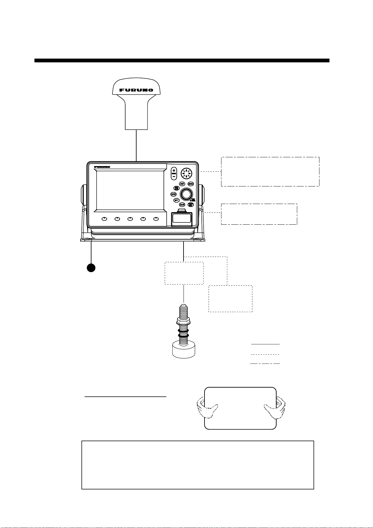
SYSTEM CONFIGURATION
ANTENNA UNIT GPA-017
DISPLAY UNIT
GP-7000F
NMEA1 and NMEA2 ports:
Radar, autopilot, video sounder,
temperature indicator, etc.
Power Source
12-24 VDC
Distributor
MB-1000*
* Required when using
1 kW transducer.
TRANSDUCER
PC/NMEA IN port:
PC, NMEA device, buzzer
Speed/Water
Temp Sensor
(option)
: Standard
: Option
: User Supply
viii
How to remove the hard cover
Place your thumbs at the center
of the cover, and then lift the cover
while pressing it with your thumbs.
This GPS receiver complies with Canadian standard RSS-210 (Low Power
License-Exempt Radio communication Devices).
Operation is subject to the following two conditions:
(1) this device may not cause interference, and
(2) this device must accept any interference, including interference that may
cause undesired operation of the device.
Page 11
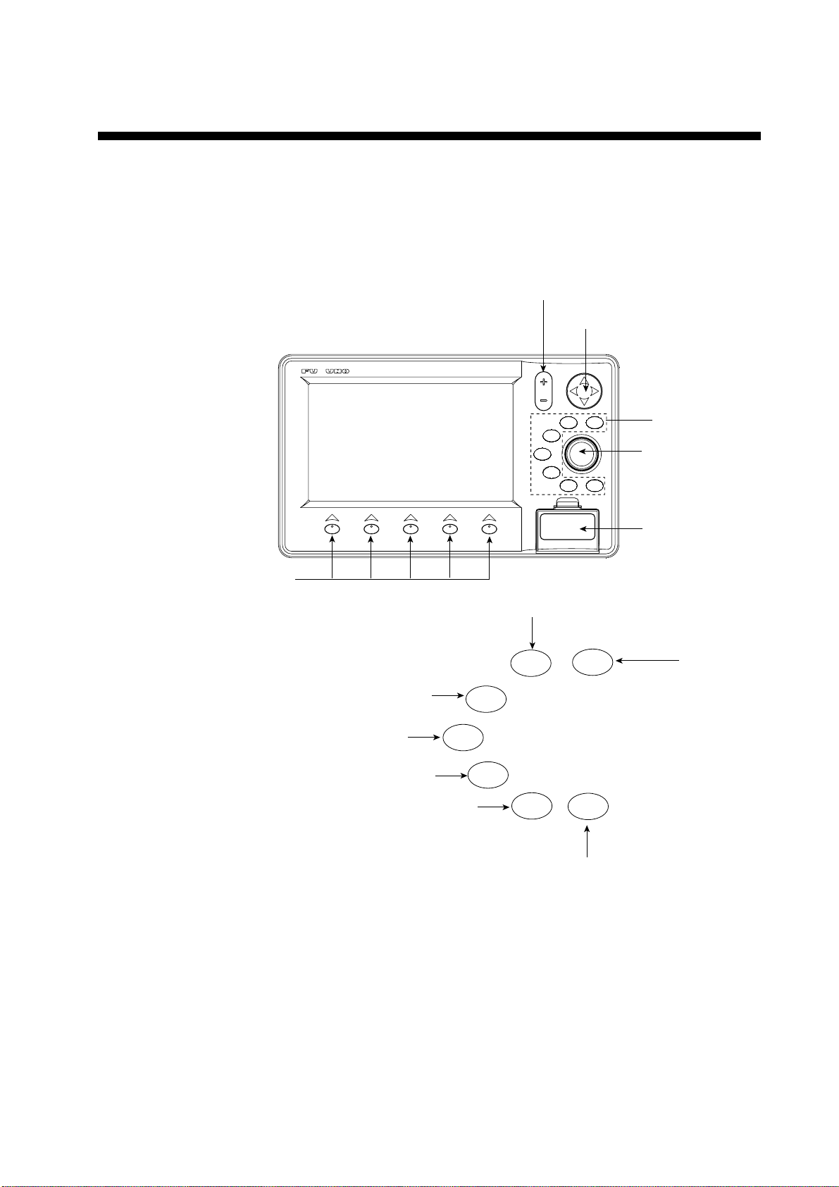
CLEAR
BRILL
POWER
GOTO
WPT
SAVE
MOB
DISP
TO ENTER
PUSH
MENU
RANGE
Soft keys
Card slot
Cursor pad
RANGE key
ENTER knob
See below.
MENU
DISP
MOB
WPT
TLL
GOTO
ROUTE
CLEAR
POWER
BRILL
Opens the menu.
Opens the DISPLAY MODE menu.
Enters waypoint or MOB mark.
Brief press:
Sets/releases the the destination.
Long press: Outputs the TLL data.
Closes the menu and window.
Silences audible alarms.
Brief press: Turns power on./Shows the brilliance setting window.
Long press: Turns power off.
Shows the route list.
1. OPERATIONAL OVERVIEW
This chapter acquaints you with the basics of your unit–from turning on the
power to the soft key menu operation.
1.1 Display Unit Controls
1-1
Display unit, front view
Page 12

1. OPERATIONAL OVERVIEW
1.2 Loading an SDTM Chart Card
Your unit reads C-MAP NT+ /NT MAX
appropriate chart card for your area before turning the power on to show chart
data automatically.
Note 1: Static electricity can be passed through your fingers to a card and
destroy the contents of the card. To prevent this, always touch a metallic
object, such as a steel desk, before handling an SD
Note 2: Do not insert or remove a card while the power is on. This may cause
the equipment to freeze.
1. Push down the lid catch to open the card slot cover.
TM
charts, stored on SDTM cards. Insert the
RANGE
SAVE
MOB
GOTO
WPT
DISP
CLEAR
MENU
TO ENTER
POWER
BRILL
PUSH
TM
card.
Lid catch
Card slot cover
Card slot cover
2. Insert appropriate SDTM chart card label side up to any slot.
Insert
direction
Inside SD chart card
SD
TM
label side up.
chart card
3. Press the center of the lid catch to close the card slot cover, to protect the
chart drive. (Keep the slot cover closed at all times.)
1-2
Page 13

1.3 Turning the Power On/Off
Turning the power on
Press the [POWER/BRILL] key until you hear a click and a beep. When the unit
is turned on, it proceeds in the sequence shown in the figure below.
1. OPERATIONAL OVERVIEW
GP-7000F
GPS PLOTTER SOUNDER
FURUNO ELECTRIC CO., LTD.
STARTUP TEST
PLOTTER
ROM : OK
RAM : OK
BACKUP DATA : OK
INTERNAL BATTERY : OK
INTERNAL GPS : OK
ECHO SOUNDER
ROM : OK
RAM : OK
POWER SETTING : 600 W (or 1 KW)
C-MAP electronic charts (ECs) are derived from
geographical data -including official government
charts - which we believe to be accurate.They are
neither verified nor approved by Hydrographic
Authorities. C-MAP ECs are designed only to ease
and speed navigation calculations and so must not
be relied upon as aprimary source of navigation
information, but rather a backup to the use of
official government charts and prudent navigation
habits.
There is no direct relationship between the color
of water areas and their depth. The navigator shall
always query the area for depth information and use
the official paper charts.
WARNING
In about 30 seconds the
last-used display appears.
You can go to the last-used
display faster by pressing any
key when this screen appears.
Start-up sequence
Note 1: The example screens shown in this manual may not match the screens
you see on your display. The screen you see depends on your system
configuration and equipment settings.
Note 2: If the message “SYSTEM HAS FAILED START UP TEST. PLEASE
CONTACT A LOCAL FURUNO REPRESENTATIVE FOR REPAIR.
PRESS ANY KEY TO CONTINUE.” appears, contact your dealer for
advice.
Note 3: At the very first time you turn on your unit, the simulation mode window
appears. Choose YES or NO as appropriate and push the [ENTER]
knob.
The equipment takes 90 seconds to find its position when turned on for the very
first time. Thereafter it takes about 12 seconds to find position each time the
power is turned on. The message “NO FIX”, which means the equipment is now
finding its position, appears at the bottom of the plotter display immediately after
turning the power on. When the GPS receiver finds its position, “NO FIX”
changes to “2D” or “3D” to show that position data is now accurate.
Turning the power off
Press and hold the [POWER/BRILL] key until the screen goes blank (about four
seconds).
1-3
Page 14

1. OPERATIONAL OVERVIEW
1.4 Adjusting Brilliance and Contrast
You can adjust display brilliance and contrast as shown below.
1. Press the [POWER/BRILL] key momentarily.
The BACKLIGHT window appears.
BACKLIGHT
ENTER TO SET
Backlight window
2. Rotate the [ENTER] knob to adjust.
Rotate clockwise to raise the setting or counterclockwise to decrease it.
To escape from this window without adjusting, press the [CLEAR] or
[POWER/BRILL] key, or wait three seconds to let the equipment close it
automatically.
3. Press the [ENTER] key to close the window.
1-4
Page 15

1.5 Selecting a Display
Fourteen screen displays are available as shown figure in below.
1. Press the [DISP] key to show the DISPLAY MODE screen.
DISPLAY MODE
1. OPERATIONAL OVERVIEW
TURN KNOB TO SELECT DISPLAY MODE AND PRESS KNOB TO ENTER.
2. Use the cursor pad or [ENTER] knob to select a mode.
To escape from the display mode screen without changing the display mode,
press the [DISP] key.
3. Press the [ENTER] knob to set the new display mode.
1.6 Soft Keys
The soft keys, their labels displayed at the bottom of the screen, provide for easy
execution of a desired function, and their label and function change according to
the display in use. When you turn on the power, the soft keys do not appear. To
show the soft keys, press any soft key. To access a soft key function, press the
appropriate soft key within five seconds after accessing them.
Display m ode s c r een
Soft keys
The soft keys disappear after five seconds. If you want to erase them earlier,
press the [CLEAR] key.
1-5
Page 16
1. OPERATIONAL OVERVIEW
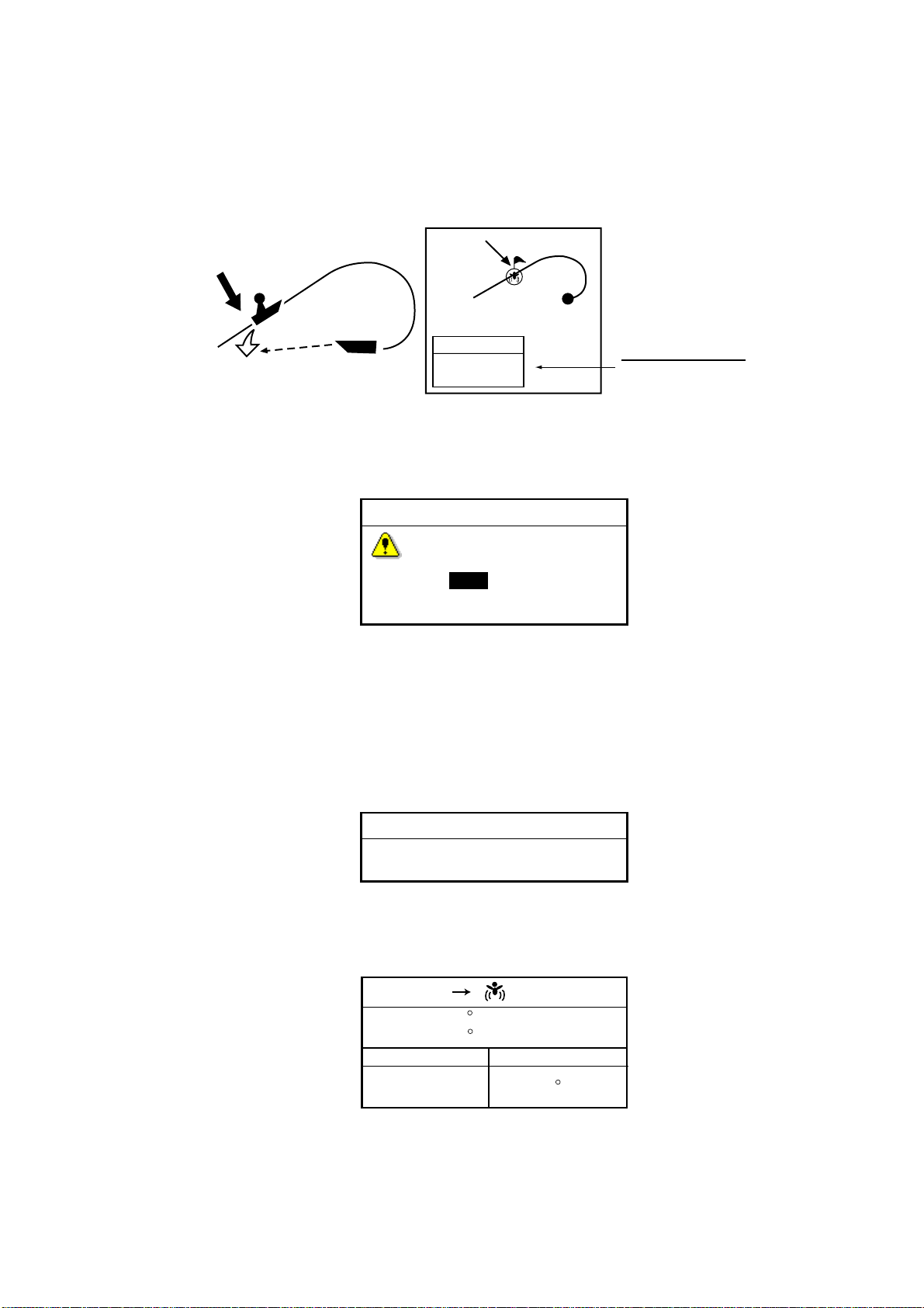
1.7 MOB Mark
1.7.1 Entering the MOB mark, setting MOB as destination
The MOB (Man Overboard) mark functions to mark man overboard position. You
can inscribe this mark from any mode.
MOB
mark
MOB
Range, bearing
MOB
Man
overboad
Current
position
162.5°M
0.49 nm
MOB concept
1. Press and hold down the [MOB/WPT] key immediately for about three
seconds when someone falls onboard, to show the display below.
MOB information
Distance and range
to MOB position
MAN OVER BOARD!
Set (MOB) as destination?
YES NO
MOB message window
2. Confirm that YES is selected, and then press the [ENTER] knob to set the
MOB position as the destination. (Choose NO to mark position as a
waypoint.)
If you select the MOB position as the destination, the MOB ALARM window
appears. Push the [ENTER] knob to erase it and then the following message
appears on the display.
MOB ALARM
MOB function is activated
MOB ALARM window
Distance and bearing to the MOB position are shown in the MOB data box when
the cursor is placed on the MOB mark.
1-6
FIX
33 07. 674N
132 51. 766W
DST
1.14 nm
MOB
BRG
187 M
MOB data box
Page 17

1.7.2 Deleting the MOB mark
1. Operate the cursor pad to place the cursor on the MOB mark, and then press
the STOP soft key to cancel the navigation to the MOB mark.
2. Press the DELETE soft key to show the confirmation window.
3. Choose “YES”, and then press the [ENTER] knob to delete the MOB mark.
The color of MOB mark changes to blue. After changing the range, the MOB
mark is cleared completely.
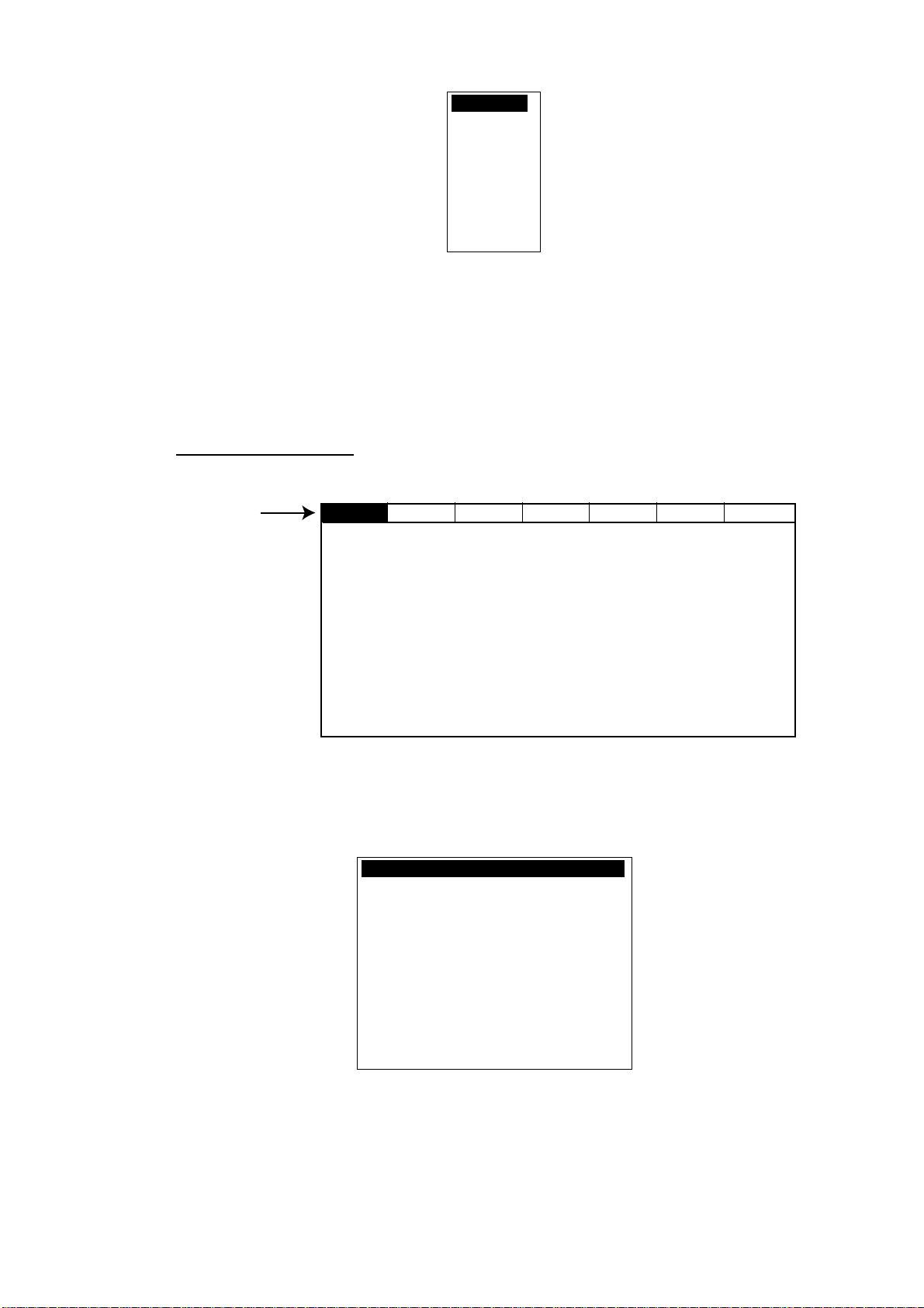
1.8 Menu Operation
Most operations are carried out from the menu bar. The menu bar is opened or
closed with the [MENU] key. Menus and options may be selected by rotating the
[ENTER] knob or operating the cursor pad. However, this manual describes
operating procedure using the [ENTER] knob.
Using the [ENTER] knob
1. Press the [MENU] key to show the menu bar.
1. OPERATIONAL OVERVIEW
Menu Bar
GENERAL PLOTTER MAP ALARMS ADVANCED INFO FIND
Menu bar
2. Rotate the [ENTER] knob to choose a menu title and then push the [ENTER]
knob to show the menu.
For example, choose GENERAL to display the GENERAL menu.
LANGUAGE English
KEYPAD BEEP Off
PALETTE Normal
TIME LINE Infinite
TIME REFERENCE UTC
TIME FORMAT 12hour
DATE FORMAT MM-DD-YY
AUTO INFO On All
SHIP ICON
WIND GRAPH True
UNITS OF MEASURE
General menu
3. Rotate the [ENTER] knob to choose an item and then push the [ENTER]
knob.
For example, choose LANGUAGE.
1-7
Page 18
1. OPERATIONAL OVERVIEW
4. Rotate the [ENTER] knob to choose the option desired and then press the
[ENTER] knob.
To cancel, press the [CLEAR] key.
5. To close all menus and option windows, press the [MENU] key.
To close option windows one by one, press the [CLEAR] key.
Using the cursor pad
1. Press the [MENU] key to show the menu bar.
English
Italiano
Francais
Deutsch
Espanol
Norsk
Svensk
Portuguese
Language option window
Menu Bar
GENERAL PLOTTER MAP ALARMS ADVANCED INFO FIND
Menu bar
2. Press ◄ or ► on the cursor pad to choose a menu title and then press ▼ to
show the corresponding menu.
For example, choose GENERAL to display the GENERAL menu.
LANGUAGE English
KEYPAD BEEP Off
PALETTE Normal
TIME LINE Infinite
TIME REFERENCE UTC
TIME FORMAT 12hour
DATE FORMAT MM-DD-YY
AUTO INFO On All
SHIP ICON
WIND GRAPH True
UNITS OF MEASURE
1-8
General menu
3. Press ▼ to choose an item and then press ► to show its option window.
For example, choose LANGUAGE.
Page 19

Language option window
4. Press ▼ to choose an option and then press ► to close the window.
To cancel, press ◄.
5. To close all menus and option windows, press the [MENU] key.
To close option windows one by one, press the [CLEAR] key.
1.9 Simulation Mode
The simulation mode, which is for use by service technicians for demonstration
purposes, provides simulated operation to help acquaint users with the functions
of the unit. All keys are operative.
“SIMUL” appears at the bottom of the display when the simulation mode is
active.
Plotter
1. OPERATIONAL OVERVIEW
English
Italiano
Francais
Deutsch
Espanol
Norsk
Svensk
Portuguese
Own ship’s mark moves from the default or selected position at the speed and
course set.
1. Press the [MENU] key to display the menu bar.
2. Rotate the [ENTER] knob to choose ADVANCED and then push the [ENTER]
knob.
3. Rotate the [ENTER] knob to choose GPS SIMULATION and then push the
[ENTER] knob to show the following window.
SIMULATION MODE Off
COURSE 007 M
SPEED 001.0 Kts
DATE Apr/02/04
TIME 12:00:00 AM
CURSOR CONTROL Off
GPS simulation window
4. Rotate the [ENTER] knob to choose SIMULATION MODE and then push the
[ENTER] knob.
5. Rotate the [ENTER] knob to choose On and then push the [ENTER] knob.
6. Rotate the [ENTER] knob to choose COURSE and then push the [ENTER]
knob.
7. Enter the course (Setting range: 0 to 359) by rotating the [ENTER] knob,
pressing the ◄ or ►, and then press the SAVE soft key.
1-9
Page 20

1. OPERATIONAL OVERVIEW
Note: You can return the value to zero by pressing the CLR FLD soft key.
8. Enter SPEED, DATE and TIME.
9. Rotate the [ENTER] knob to choose CURSOR CONTROL and then push the
[ENTER] knob.
10. Rotate the [ENTER] knob to choose On or Off as appropriate and then push
the [ENTER] knob.
When On is selected, you can set course value (◄ ►) and speed value (▲ ▼)
on the simulation plotter display.
When you select On, the cursor does not appear on the plotter menu.
11. Rotate the [ENTER] knob to choose SELECT POSITION and then push the
[ENTER] knob.
The plotter display appears.
12. Operate the cursor pad to place the cursor at the desired starting point.
13. Push the [ENTER] knob to move the own ship mark on the cursor.
14. Press the [CLEAR] key.
Echo sounder
1. Press the [MENU] key to show the menu bar on the plotter display.
2. Rotate the [ENTER] knob to choose ADVANCE and then push the [ENTER]
knob.
3. Rotate the [ENTER] knob to choose ECHO SOUNDER SIMULATION and
then push the [ENTER] knob.
4. Rotate the [ENTER] knob to choose On and then push the [ENTER] knob.
5. Press the [MENU] key to close the menu.
6. Choose the sounder display on the display mode screen.
1-10
Page 21
2. PLOTTER DISPLAYS
2.1 Presentation Modes
The plotter display mainly shows chart, ship’s track, waypoints, and navigation
data.
Three types of display presentations are provided for the normal plotter display:
north-up, course-up and auto course-up. To change the mode, use the
presentation mode selection soft key, which is the leftmost soft key.
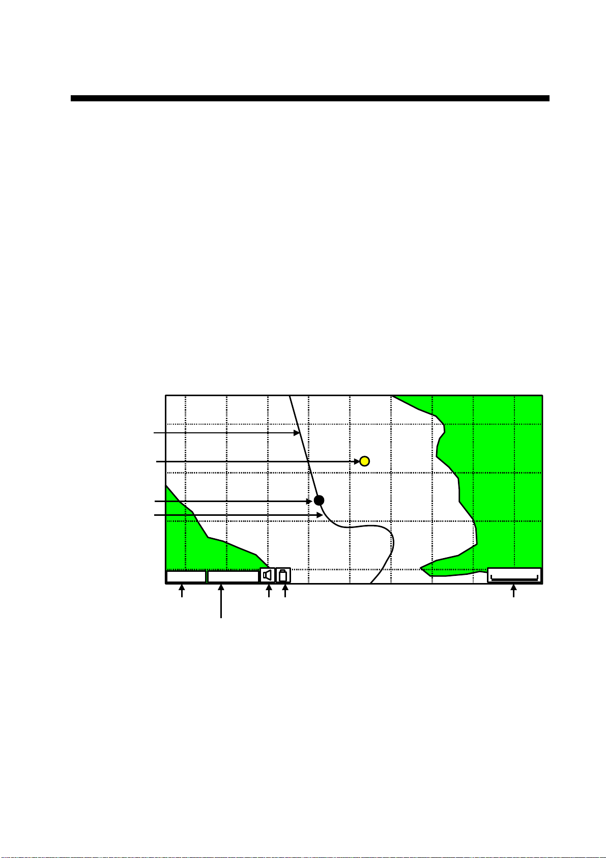
2.1.1 North-up
1. Press any soft key to show the soft key labels.
2. Press the NORTH UP soft key to show the north-up display. North (zero
degree) is at the top of the display.
When the cursor is on, the own ship moves and the chart is fixed. (True motion)
When the cursor is off, the chart, waypoints and other marks move and own ship
is fixed. (Relative motion)
To turn the cursor off, press the CENTER soft key.
Course bar
Waypoint
Own ship marker
Track
GPSW2D
GPS status
Icons
Current display mode
(north-up)
Plotter display, north-up mode
0001WPT
1 nm
Range scale
2-1
Page 22

2. PLOTTER DISPLAY
2.1.2 Course-up
Press the COURSE UP soft key to show the course-up display. When
destination is set, it is at the top of the screen and the north mark appears at the
upper right side of the screen and points to north.
When destination is not set, the course is upward on the screen at the moment
the course-up mode is selected.
COURSE UP CENTER
NAV DATA
2.1.3 Auto course-up
Press the AUTO CSE UP soft key to show the automatic course-up display. The
course or heading is at the top of screen at the moment the auto course-up
mode is selected. When own ship is off its intended course by 30º (default
setting, this degree can be changed on NAVIGATION menu. For details, see
chapter 8.) or more, it is automatically brought back to perpendicular.
0001WP
MAP SETUP
Plotter display, course-up mode
N
1
nm
SEARCH
2-2
0001WP
AUTO CSE UP CENTER
NAV DATA
MAP SETUP
SEARCH
N
1 nm
Plotter display, auto course-up mode
Page 23

2.2 Cursor
2.2.1 Turning on the cursor, shifting the cursor
Press the cursor pad to turn the cursor on, and the cursor appears at the own
ship’s position. Operate the cursor pad to shift the cursor. The cursor moves in
the direction of the arrow or diagonal pressed on the cursor pad.
Cursor state determines what data is shown in the NAVDATA window. This
window can be enabled or disabled by pressing the NAVDATA ON soft key.
NAVDATA window
Also, when the cursor is placed on own ship’s position, its data is shown as
follows.
2. PLOTTER DISPLAY
FIX 3D
33 37.125N
118 48.428W
SOG COG
1.00 kts 007 M
Own ship’s position data window
2.2.2 Moving the cursor to the center of the screen
Press the CENTER soft key to return the cursor to the screen center.
2-3
Page 24
2. PLOTTER DISPLAY
2.2.3 Displaying data
Besides its fundamental functions of providing position data, the cursor can also
provide data for chosen caution area, depth area, source of data, etc. Further,
you can display information about an icon by placing the cursor on it.
1. Press the cursor pad to turn the cursor on.
2. Use the cursor pad to place the cursor on the position desired.
The object information window appears.
Object information window (ex. wreck)
3. If you want to know more details, press the Details soft key.
Objects
Wreck
Caution area
Depth area
Military practice area
Sea area
Source of data
Object Info
Wreck
Wreck
Category of wreck
non-dangerous wreck
Water level effect
always under water/submerged
Object detail window (ex. wreck)
4. Rotate the [ENTER] knob to choose the item you want to know more about.
Detailed information appears in the lower column.
5. Press the [CLEAR] key to close the window.
2.3 Selecting Chart Scale/Range
Chart scale (range) may be selected with the [RANGE] key. The [RANGE +] key
zooms in the chart; [RANGE -] key zooms out it.
2-4
Page 25
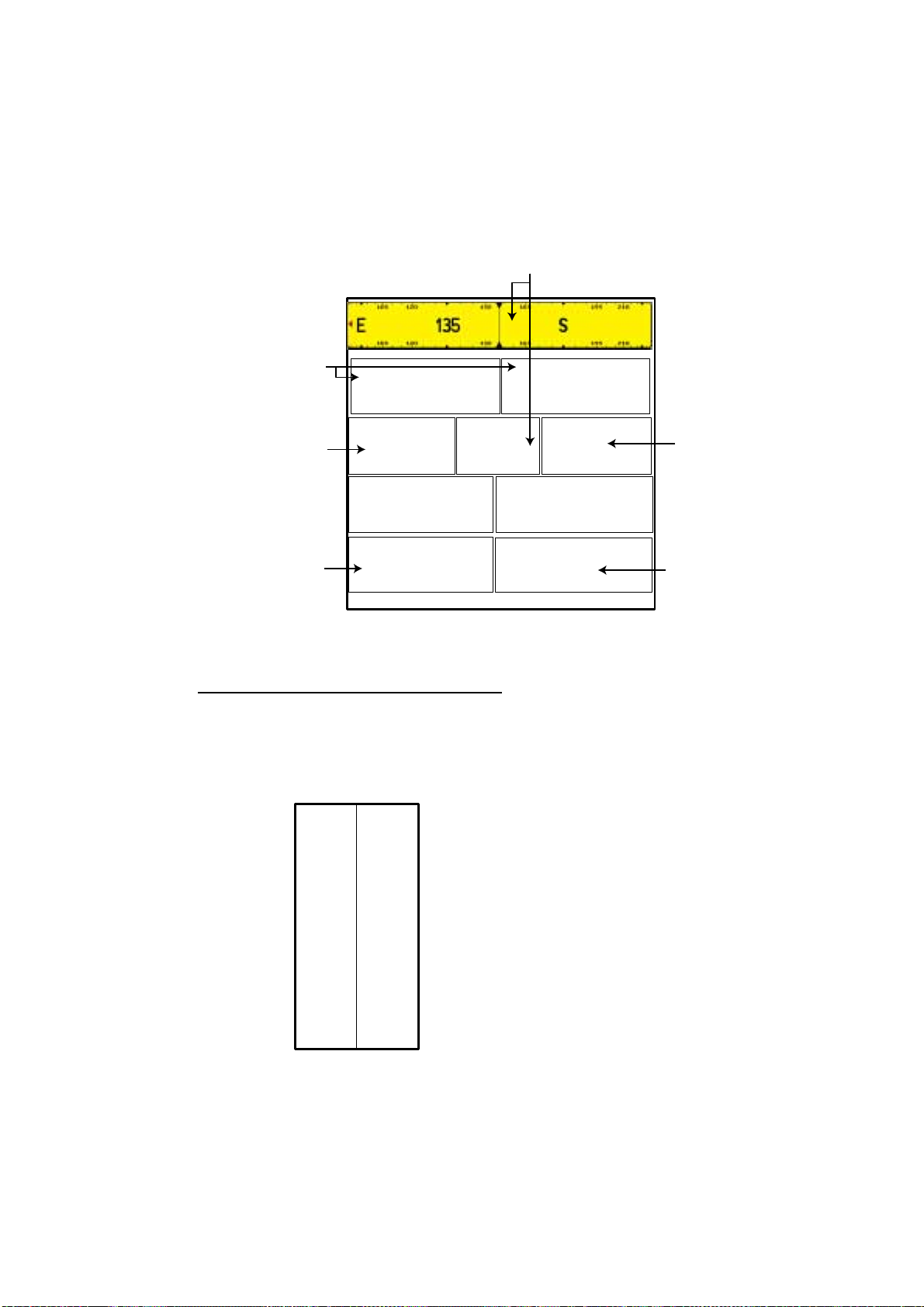
2.4 Navigation Data Display
03.730
37º57.870
8
The navigation data display provides generic navigation data, and it is shown in
combination displays.
Appropriate sensors are required. Bars (- -) appear when corresponding sensor
is not connected.
Course
2. PLOTTER DISPLAY
Position
Speed
Depth
LATITUDE
22º
SOG
S
DATE
Apr/17/04
DEPTH
N
COG
º
LONGITUDE
1
TRIP
TIME
12:2
TEMP
AM
E
Trip meter
Temperature
º
Navigation data display
Changing the information displayed
1. Press and hold the [MENU] key down for two seconds to show Speed in
reverse video.
2. Rotate the [ENTER] knob to show data in reverse video.
3. Press the [ENTER] knob to show the selection window as shown below.
SOG
COG
STW
HDG
DST
BRG
TRIP
DEPTH
TEMP
HDOP
VDOP
XTE
DRF
SET
WST
WDT
WSA
WDA
DATE
TIME
TTG
ETA
DEST
Note: Contents may be changed
depending on data selected at step2.
4. Rotate the [ENTER] knob to choose the data to show, and then press it.
The item window (ex. units) appears.
5. Rotate [ENTER] knob to select the unit.
The data selected at step 2 changes to your selection.
6. Press the [CLEAR] key to erase the reverse video.
2-5
Page 26
2. PLOTTER DISPLAY
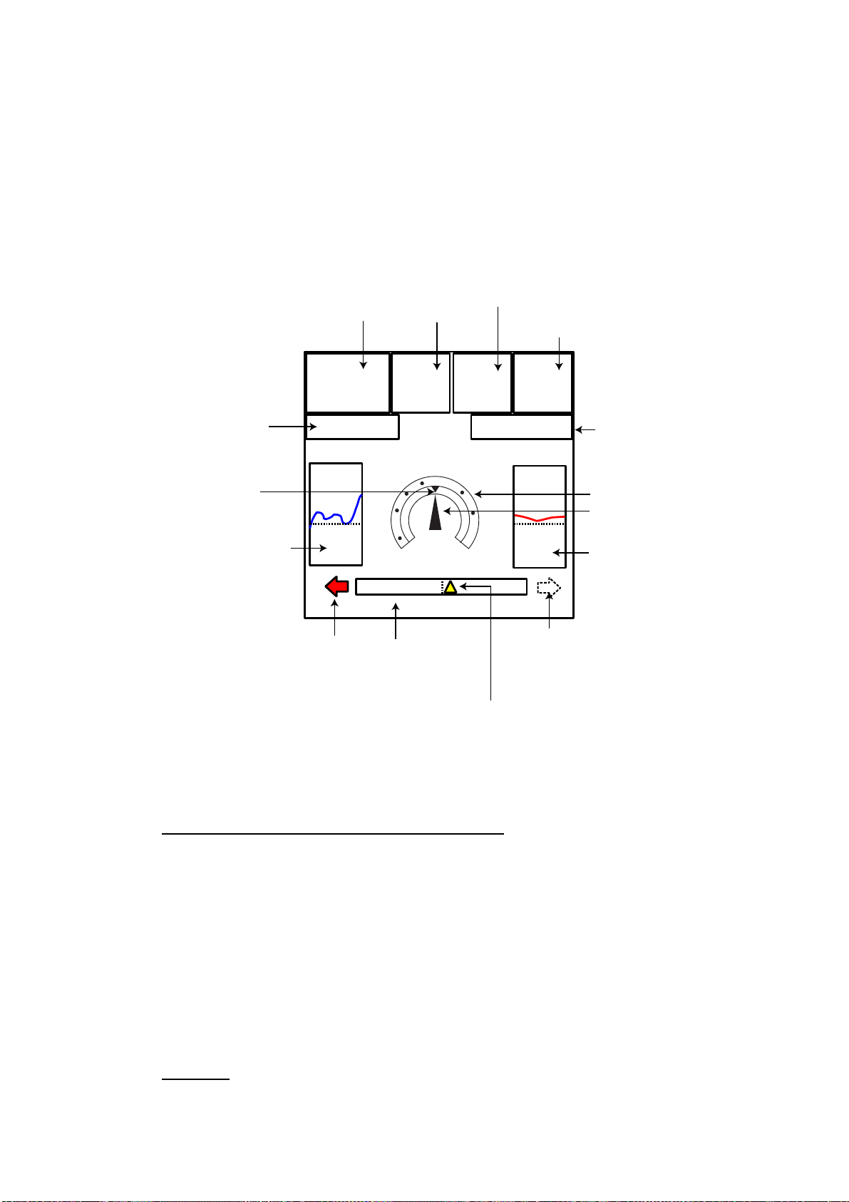
2.5 Compass Display
The compass display, shown in combination displays, provides steering
information. The compass rose shows two triangles: the red triangle shows own
ship’s course and the black triangle, which moves with ship’s course, shows the
bearing to destination waypoint.
The water temperature and depth graphs, which require appropriate sensors,
shows the latest 10 minutes of water temperature and depth data.
Time-to-go
to destination
Destination
waypoint
bearing
(black)
Depth
graph**
Shown (in red)
when direstion to
steer is "left".
Speed
Destination
waypoint
DEST:
0001WP
TTG:25:26
DPT
45.6ft
0.5 0.5
XTE monitor
(See below for
description.)
through
water
STW*
12.4
KTS
155º
N
w
Range to destination waypoint
Speed over ground
DST*
305.3
nm
E
SOG*
12.0
Kts
ETA:12:28AM
TMP
40.4ºF
Shown (in green)
when direction to
steer is "right."
Estimated time of
arrival at destination
Bearing scale
Ship's course
(red)
Water temperature
graph**
Own ship marker
(Yellow)
**: Appropriate sensor is required.
Compass distance
Reading t he XTE (cross-track error) mon itor
The XTE monitor, located below the compass rose, shows the distance you are
off course and the direction to steer to return to course. The own ship marker in
the monitor moves according to direction and distance off course. An arrow
appears at the right or left side of the XTE monitor and it shows the direction to
steer to return to intended course. It is shown in red when you should steer left,
and green when you should steer right. In the example above you would steer
left to return to course. To maintain course, steer the vessel so the own ship
marker stays at the center of the XTE monitor. Note that the XTE range can be
changed by rotating the [ENTER] knob.
Nav dat a
Data marked with * in above can be changed to display. See page 2-5.
2-6
Page 27

2.6 Highway Display
The highway display, shown in combination display with the plotter screen,
provides a graphic presentation of ship’s track along intended course. It is useful
for monitoring ship’s progress toward a waypoint. The own ship marker shows
the relation between your vessel and intended course.
Current time
2. PLOTTER DISPLAY
Speed
TIME*
12:28AM
Bearing of
destination
waypoint
Turn knob to change scale: 0.2nm
SOG*
12.0KTs
COG*
044º
Course
Destination waypoint
(Flag)
Intended course
Own ship marker
Highway display
Changing the scale
You can change the scale of the highway display to 0.2, 0.5, 1.0, 2.0, 4.0 or 10.0
(nm). Rotate the [ENTER] knob to change it. Note that the available range
depends on own ship’s position.
Nav dat a
Data marked with * in above can be changed to display. See page 2-5.
2-7
Page 28
2. PLOTTER DISPLAY
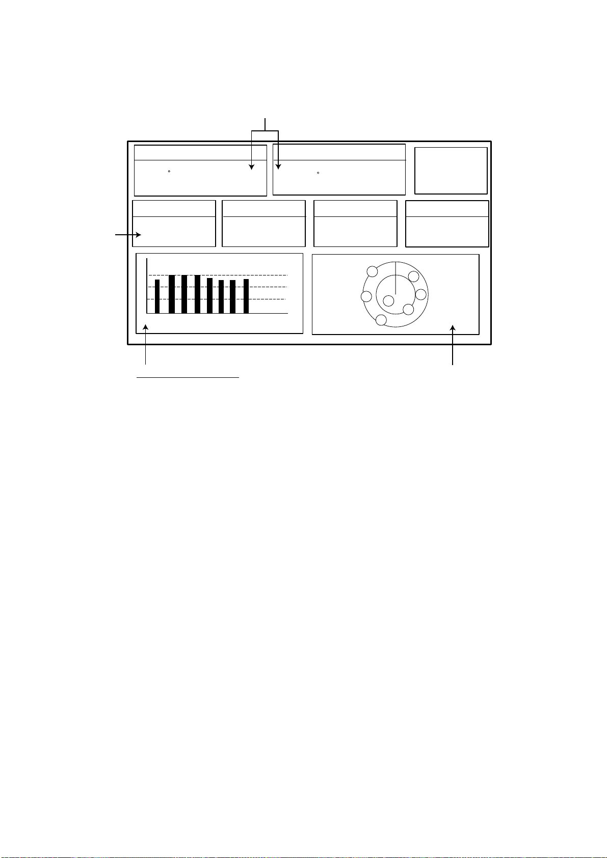
2.7 GPS Status Display
The GPS status display provides data on the GPS satellites.
Position
DOP value
LATITUDE
33 18.426N
HDOP
SOG Kts
12.5
07 14 25 31 -- -01 11 20 28 -- --
Receive signal level:
Bars show satellite
signal level. Satellites
in brown are used in
fixing position.
1.00
LONGITUDE
131 48.608W
DATE
Apr/02/04
07
28
Estimated position in the sky,
and satellite number in brown circle
is used for positioning.
GPS status display
ACQUIRING
TIME
12:09 AM
14
11
01
25
31
2-8
Page 29
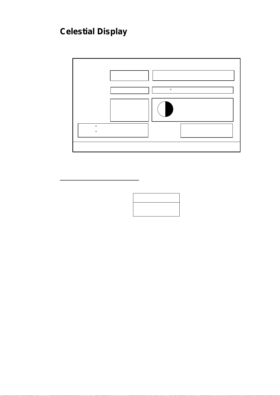
2.8 Celestial Display
Tide, Celestial Display
Your plotter provides for calculation of the tide heights for any date. Additionally it
displays the time of sunrise, sunset, moonrise and moonset.
Nearest Tide Station:
2. PLOTTER DISPLAY
High Water
Low Water
From tide
Sunrise:
Sunset:
Moonrise:
Moonset:
33 20. 435N
131 48.608W
ENTER to change Date - Turn the KNOB to set [DLS/STANDARD] time
- - - - -
- - - - -
- -.- - nm
03:50 PM U
01:49 AM U
10:29 AM U
10:07 PM U
- . - - ft
- . - - ft
- - - M
Date
Time
Moon phase
50%
April-01-2004
02:35
Tide, celestial display
Setting the date for calculation
1. Press the [ENTER] knob to show the date window.
MM-DD-YY
04/09/04
Date window
2. Press the cursor pad to move the cursor, and then rotate the [ENTER] knob
to choose the date.
When you want to clear all values, press the CLR FLD soft key.
To escape, press the CANCEL soft key.
3. Press the SAVE soft key to set.
2-9
Page 30
2. PLOTTER DISPLAY
2.9 Graph Display
Four graphs can be displayed alternately on the half-screen of the LCD: depth,
wind, water temperature and SOG (speed).
Press the GRAPH TYPE soft key to choose display graphs in the sequence
shown below.
Note: Appropriate sensors required to display graphs.
Depth Graph Page 1 of 4
10.2
20.2
30.2
40.2
03:33
GRAPH TYPE
soft key
SOG Graph Page 4 of 4
1.2
1.0
0.7
03:34 03:35
Depth graph
9.6 Ft
1.0 kts
GRAPH TYPE
soft key
GRAPH TYPE
soft key
Wind Graph Page 2 of 4
3.1 knot
4.2
3.2
2.2
1.2
03:33
Water Temp. Graph Page 3 of 4
69.2
68.2
67.2
03:34 03:35
Wind graph
GRAPH TYPE
soft key
67.4 F
0.5
03:33
03:34 03:35
SOG graph
66.2
Sequence of graph display
03:33
Water temperature graph
03:34 03:35
2-10
Page 31

2.10 Wind Display
Your plotter can show the graphical wind indicator when the appropriate data is
input.
2. PLOTTER DISPLAY
WIND
60
TRUE
30
HEAD
0
7º M
30
60
- - -
90
120
150
- - -
180
Kts
Wind display
Selecting the wind directi on indication format
The wind direction can be selected to true or apparent.
1. Press the [MENU] key to show the menu bar.
2. Rotate the [ENTER] knob to choose GENERAL and then push the [ENTER]
knob.
3. Rotate the [ENTER] knob to choose WIND GRAPH and then push the
[ENTER] knob.
4. Rotate the [ENTER] knob to select True or Apparent as appropriate.
True: The Speed and direction (relative to due north)
Apparent: The direction (in relation to ship’s bow) and speed of the wind as it
appears to those on board, relative to the speed and direction of the
boat; combination of the true wind and the wind caused by the boat’s
movement.
5. Push the [ENTER] knob.
6. Press the [MENU] key to close the menu.
90
120
150
2-11
Page 32

2. PLOTTER DISPLAY
2.11 NAVDATA Window
The second soft key from the left functions to control the NAVDATA window.
Each press of the key changes this soft key label in the sequence of NAV DATA,
NAV+CUR and OFF.
NAVDATA window
Customizing the NAVDATA window
1. Press the NAV DATA soft key to show the NAVDATA window if it is not
already shown.
2. Press and hold the [MENU] key down for two seconds.
The data beneath the cursor position is shown in reverse video.
3. Rotate the [ENTER] knob to select the data to change, and then press it.
A data window similar to the one shown on page 2-5 appears.
4. Rotate the [ENTER] knob to choose data, and then press it.
5. Depending on the data selected, a unit window may appear. In this case,
rotate the [ENTER] knob to choose the desired unit, and then press it.
6. Press the [CLEAR] key to erase the reverse video.
Resetting the trip data
1. Press the NAV DATA soft key to show the NAVDATA window if it is not
already shown.
2. Press and hold the [ENTER] knob down for two seconds.
3. Rotate the [ENTER] knob to choose TRIP, and then press it.
4. Confirm that TRIP is shown in reverse video in the list, and then press the
[ENTER] knob.
5. Rotate the [ENTER] knob to choose Reset, and then press it.
6. Confirm that YES is shown in reverse video, and then press the [ENTER]
knob.
7. Press the [CLEAR] key to close the window.
2-12
Page 33

3. TRACK
Your ship’s track is plotted on the screen using navigation data fed from the
internal GPS navigator. This chapter shows you what you can do with track, from
turning it on or off to changing its plotting interval. In the default setting, own
ship’s track is turned on and is displayed in black.
3.1 Selecting Active Track
Your plotter can plot up to five track lines. It can be useful to have multiple track
lines to distinguish tracks according to date or course. Note that other
track-related settings are available for the track chosen here.
1. Press the [MENU] key to show the menu bar.
Menu Bar
GENERAL PLOTTER MAP ALARMS ADVANCED INFO FIND
Menu bar
2. Rotate the [ENTER] knob to choose PLOTTER from the menu bar.
3. Push the [ENTER] knob to show the PLOTTER menu.
TRACK
ROUTES
WAYPOINTS
MEMORY CARD
TRACK 11999/12000
WAYPOINTS 12/2000
Number of tracks and waypoints in use
Plotter menu
4. Rotate the [ENTER] knob to choose TRACK and then push the [ENTER]
knob.
TRACKING OffNAVIGATE
ACTIVE TRACK 1
VISIBLE On
LINE COLOR
DELETE
STEP UNIT Dist
DISTANCE 0.1 Nm
TIME 1 min
Track menu
3-1
Page 34

3. TRACK
5. Rotate the [ENTER] knob to choose ACTIVE TRACK and then push the
[ENTER] knob.
6. Rotate the [ENTER] knob to choose the desired number of own ship tracks to
use, from among 1 to 5.
7. Press the SAVE soft key.
8. Press the [MENU] key to close the menu.
3.2 Displaying Track
To display track line on the screen, do the following.
1. Press the [MENU] key to show the menu bar.
2. Rotate the [ENTER] knob to choose PLOTTER from the menu bar and then
push the [ENTER] knob.
3. Rotate the [ENTER] knob to choose TRACK and then push the [ENTER]
knob.
4. Rotate the [ENTER] knob to choose TRACKING and then push the [ENTER]
knob.
5. Rotate the [ENTER] knob to select On and then push the [ENTER] knob.
To turn off the track display, select Off here.
6. Press the [MENU] key to close the menu.
3.3 Changing Track Color
Track can be displayed in black (default setting), light-green, red, pink, yellow,
gray, brown and dark green. It can be useful to change track color on a regular
basis to discriminate the active tracks.
1. Choose TRACK from the PLOTTER menu and then push the [ENTER] knob.
2. Choose LINE COLOR and then push the [ENTER] knob.
3. Rotate the [ENTER] knob to choose the color desired and then push the
[ENTER] knob.
4. Press the [MENU] key to close the menu.
3.4 Stopping, Restarting Plotting
When your boat is at anchor or returning to port, you probably won’t need to
record its track. You can stop recording the track, to conserve the track memory,
as below.
1. Choose TRACK from the PLOTTER menu and then push the [ENTER] knob.
2. Choose TRACKING and then push the [ENTER] knob.
3. Rotate the [ENTER] knob to choose Off, and then push the [ENTER] knob.
3-2
Page 35

3.5 Hiding the Track
The track lines can be hidden (but recorded). This function is useful when there
are too many tracks to distinguish on the screen and it is hard to distinguish one
from another.
1. Choose TRACK from the PLOTTER menu and then push the [ENTER] knob.
2. Choose VISIBLE and then push the [ENTER] knob.
3. Rotate the [ENTER] knob to select On.
To re-display the track, choose Off.
4. Press the [MENU] key to close the menu.
3.6 Track Plotting Method and Interval
In drawing the own ship track, first the ship’s position fed from the internal GPS
navigator is stored into the unit’s memory at an interval of time or distance. A
shorter interval provides for better reconstruction of the track, but the storage
time of the track is reduced. When the track memory becomes full, the oldest
track is erased to make room for the latest.
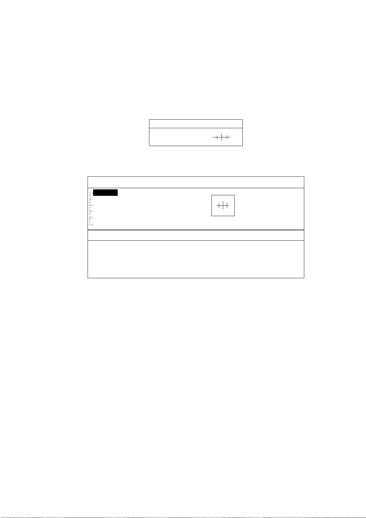
3.6.1 Track plotting method
3. TRACK
Track may be plotted by time or distance.
1. Choose TRACK from the PLOTTER menu.
2. Choose STEP UNIT and then push the [ENTER] knob.
Dist
Time
STEP UNIT window
3. Rotate the [ENTER] knob to select Dist (distance) or Time as appropriate.
Distance is useful for conserving track memory, since no track is recorded when
the boat is stationary.
4. Push the [ENTER] knob.
5. Press the [MENU] key to close the menu.
3-3
Page 36

3. TRACK
3.6.2 Track plotting interval
1. Choose TRACK from the PLOTTER menu.
2. Choose DISTANCE or TIME as appropriate and then push the [ENTER]
knob.
0.01
0.05
0.1
0.5
1.0
2.0
5.0
10.0
Distance window Time window
3. Rotate the [ENTER] knob to select setting.
4. Push the [ENTER] knob.
5. Press the [MENU] key to close the menu.
1sec
5 sec
10 sec
30 sec
1 min
5 min
10 min
30 min
1 h
Interval windows
3.7 Erasing Track
This section shows you how to erase the active track.
1. Choose TRACK from the PLOTTER menu.
2. Choose DELETE and then push the [ENTER] knob.
3. Push the [ENTER] knob to erase the track.
To cancel, rotate the [ENTER] knob to choose NO and then push the [ENTER]
knob.
4. Press the [MENU] key.
WARNING
Delete Track
Are you sure?
YES NO
Delete window
3-4
Page 37

4. WAYPOINT
In navigation terminology, a waypoint is a particular location on a voyage
whether it be a starting, intermediate or destination point. A waypoint is the
simplest piece of information your equipment requires to get you to a destination,
in the shortest distance possible.
This unit has 2,000 waypoints into which you can enter position information. You
may enter a waypoint four ways: at own ship position, by cursor, at MOB position
(see chapter 1) and through the waypoint list (manual input of latitude and
longitude).
4.1 Entering Waypoints
4.1.1 Enteri n g a waypoint at ow n sh ip p os itio n or cur s or posi tion
Turn the cursor off to enter a waypoint at own ship position, or turn it on to enter
a waypoint at cursor position.
A newly entered waypoint is saved to the waypoint list, under the youngest
empty waypoint number.
1. Press the [MOB/ WPT] key momentarily to store your position as a waypoint.
When the cursor is displayed, the waypoint is entered at the cursor position.
The new waypoint window appears and it shows waypoint name, position of
waypoint, waypoint mark shape and comment for newly entered waypoint.
NAME
0004WP
LATITUDE/LONGITUDE
47 56.307N
133 56.807W
SHAPE
COLOR
COMMENT
00:29 APR0204
Waypoi nt window
2. If you do not need to change the waypoint data, press the SAVE soft key to
register the waypoint. The steps which follow show you how to change
waypoint data.
3. NAME is selected; push the [ENTER] knob.
4-1
Page 38

4. WAYPOINT
4. Rotate the [ENTER] knob to choose the desired alphanumeric character.
5. Press ► to move the cursor to the next digit, and then rotate the [ENTER]
6. Repeat steps 4 and 5 to complete the name. (Max. 12 characters)
7. Press the SAVE soft key and then rotate the [ENTER] knob to choose the
8. Push the [ENTER] knob.
9. Use the cursor pad and [ENTER] knob to enter latitude data, and then press
10. Use the cursor pad and [ENTER] knob to enter longitude data, and then
11. Rotate the [ENTER] knob to choose “SHAPE” in the SHAPE/COLOR section.
12. Push the [ENTER] knob to show the waypoint mark shape selection window.
You can clear all digits in the field by pressing the CLR FLD soft key.
knob to choose the character desired.
LATITUDE/LONGITUDE section.
the SAVE soft key.
press the SAVE soft key.
Waypoi nt mark shape select ion window
13. Rotate the [ENTER] knob to choose shape desired.
14. Push the [ENTER] knob.
15. Rotate the [ENTER] knob to choose “COLOR” and then push the [ENTER]
knob.
Waypoint mark color selection window
16. Rotate the [ENTER] knob to choose the color desired, then push the
[ENTER] knob.
17. Rotate the [ENTER] knob to choose COMMENT section and then push the
[ENTER] knob.
18. Use the cursor pad and [ENTER] knob to enter a comment (Max. 13
characters).
19. Press the SAVE soft key twice to register the waypoint.
4-2
Page 39

4.1.2 Enteri n g a wa ypoi nt fr om th e w a ypo i nt lis t
You can manually enter waypoint position from the waypoint list as follows.
1. Press the [MENU] key to show the menu bar.
2. Rotate the [ENTER] knob to choose PLOTTER and then push the [ENTER]
knob to show the PLOTTER menu.
TRACK
ROUTES
WAYPOINTS
MEMORY CARD
TRACK 11999/12000
WAYPOINTS 12/2000
Plotter menu
3. Rotate the [ENTER] knob to choose WAYPOINTS and then push the
[ENTER] knob.
The WAYPOINT LIST is displayed.
WAYPOINT LIST
Number of tracks and waypoints in use
4. WAYPOINT
NAME
SYM TYPE
COMMENT
0001WP
00:58 MAY3104
ICON SEARCH PLOT EDIT NEW
MODE DELETE SORT SEND RECEIVE
WPT
LATITUDE
LONGITUDE
34 34. 641 N
135 09. 912 E
DST [nm}
BRG [M]
6.669
045
MODE
SHOWN
Waypoint list
4. Rotate the [ENTER] knob to choose NEW at the bottom of the screen and
then push the [ENTER] knob.
The new waypoint is entered at the current own ship position. (When cursor is
turned on, it is entered at the cursor position.)
5. If desired, change waypoint data; choose EDIT (at the bottom of screen) and
follow the paragraph 4.2.
6. Press the [CLEAR] key to close the WAYPOINT LIST.
Note 1: The WAYPOINT LIST can also be shown by pressing the WPT/QWP
LST soft key, which is shown when the cursor is placed on a waypoint.
Note 2: You can change the page of the WAYPOINT LIST by pressing ◄ or ►.
4-3
Page 40

4. WAYPOINT
4.1.3 Enterin g a wa ypoint/M OB mark with an extern al e ven t swit ch
If the equipment is equipped with an external event switch you may choose what
mark is inscribed on the screen when the switch is pressed. The choices are
Waypoint, MOB mark or Off (no event switch is connected).
1. Press the [MENU] key to show the menu bar.
2. Rotate the [ENTER] knob to choose ADVANCED from the menu bar and then
push the [ENTER] knob.
3. Rotate the [ENTER] knob to choose INPUT/OUTPUT and then push the
[ENTER] knob.
4. Rotate the [ENTER] knob to choose EXTERNAL EVENT and then push the
[ENTER] knob.
Off
WPT
MOB
5. Choose Off, WPT or MOB as appropriate and then push the [ENTER] knob.
6. Press the [MENU] key to close the menu.
4-4
Page 41

4.2 Editing Waypoint Data
Waypoint data may be edited from the waypoint list or directly from the plotter
display.
4.2.1 Editing waypoint data from the waypoint list
1. Press the [MENU] key to show the menu bar.
2. Rotate the [ENTER] knob to choose PLOTTER and then push the [ENTER]
knob.
3. Rotate the [ENTER] knob to choose WAYPOINTS and then push the
[ENTER] knob to show the WAYPOINT LIST.
4. Press the cursor pad (▲▼) to choose the waypoint you want to edit.
5. Rotate the [ENTER] knob to choose EDIT at the bottom of screen.
6. Push the [ENTER] knob.
7. Press the cursor pad (◄►) to place the cursor on the appropriate column,
and then push the [ENTER] knob.
8. Edit data as appropriate, and then push the [ENTER] knob.
9. Press the [CLEAR] key to close the list.
4. WAYPOINT
4.2.2 Editing a waypoint from the plotter display
You may edit waypoints from the plotter display two ways: from the waypoint
window or directly on the plotter display.
From waypoint window
1. Operate the cursor pad to place the cursor on the waypoint you want to edit.
2. Press the EDIT soft key to show the waypoint window.
3. Edit data as appropriate referring to paragraph 4.1.1, and then press the
SAVE soft key.
Directly on plotter display
NAME
0004WP
LATITUDE/LONGITUDE
47 56.307N
133 56.807W
SHAPE
COLOR
COMMENT
00:29 APR0204
Waypoi nt window
Operate the cursor pad to place the cursor on the waypoint to edit, and then
press the MOVE soft key. The color of the selected waypoint changes to blue,
and black line runs between it and the cursor. Operate the cursor pad to select
the new position, and then push the [ENTER] knob.
4-5
Page 42

4. WAYPOINT
4.3 Erasing Waypoints
Waypoints can be erased from the waypoint list or directly from the plotter
display.
4.3.1 Erasing a wa ypo in t dir ec tl y from th e plo tt er dis play
1. Press the cursor pad to place the cursor on the waypoint you want to delete.
2. Press the DELETE soft key.
The following window appears.
WARNING
Delete 0001WP
Are you sure?
YES NO
3. Push the [ENTER] knob.
The color of the selected waypoint at step 1 changes to blue. To erase
completely, press the [RANGE] key.
4.3.2 Erasing a waypoint from the waypoint list
1. Press the [MENU] key to show the menu bar.
2. Choose PLOTTER followed by WAYPOINTS, and then push the [ENTER]
knob to show the WAYPOINT LIST.
3. Press the cursor pad (▲▼) to choose the waypoint you want to delete.
4. Rotate the [ENTER] knob to choose DELETE at the bottom of the screen,
and then push the [ENTER] knob.
MODE
DELETE SELECTED
DELETE ALL
5. Rotate the [ENTER] knob to select DELETE SELECTED, and then push the
[ENTER] knob.
If you want to delete all waypoints in the list, choose DELETE ALL.
WARNING
Delete points
Are you sure?
YES NO
4-6
6. You are asked if you are sure to delete selected waypoint (s). Push the
[ENTER] knob to delete, or choose NO and push the [ENTER] knob to
escape.
7. Press the [CLEAR] key to finish.
Page 43

4.4 Searching, Sorting Waypoints
You can search and sort waypoints on the waypoint list as follows.
Searching by waypoint name
1. Open the WAYPOINT LIST.
2. Rotate the [ENTER] knob to choose SEARCH at the bottom of the screen.
3. Push the [ENTER] knob.
4. Enter the waypoint name you want to find, and then press the SAVE soft key.
The cursor moves on the chosen waypoint name on the list.
5. Press the [CLEAR] key to close the list.
Sorting waypoints
1. Open the WAYPOINT LIST.
2. Rotate the [ENTER] knob to choose SORT at the bottom of the screen.
3. Push the [ENTER] knob to show the item window.
4. WAYPOINT
A-Z ASCENDING
Z-A DESCENDING
DISTANCE ASC
DISTANCE DESC
Sort window
4. Rotate the [ENTER] knob to choose a sorting method.
A-Z ASCENDING: Sorting waypoints in ascending alphanumeric order.
Z-A DESCENDING: Sorting waypoint in descending alphanumeric order.
DISTANCE ASC: Sorting waypoints in order of increasing distance to own ship.
DISTANCE DESC: Sorting waypoints in order of decreasing distance to own
ship.
5. Push the [ENTER] knob.
6. Press the [CLEAR] key to close the list.
4-7
Page 44

4. WAYPOINT
4.5 Other Waypoint List Functions
This section shows you how to execute the various functions available on the
WAYPOINT LIST.
4.5.1 Filterin g waypoints by mark shap e
You may filter waypoints in the waypoint list by mark shape. This is useful when
you are looking for waypoints of a specific shape.
1. Open the WAYPOINT LIST.
2. Rotate the [ENTER] knob to choose ICON at the bottom of screen.
3. Push the [ENTER] knob to show the ICON window.
ICON
SELECT
ALL
Icon wi ndow
4. Rotate the [ENTER] knob to choose SELECT and then push the [ENTER]
knob.
The waypoint mark shape selection window appears.
Waypoi nt mark shape select ion window
Note: ALL shows all waypoints.
5. Rotate the [ENTER] knob to choose the mark shape which you want to
search, and then push the [ENTER] knob.
The list shows waypoints with the chosen mark shape.
6. Press the [CLEAR] key twice to close the list.
To display all waypoints, choose ALL at step 4 and then press the [CLEAR] key.
4-8
Page 45

4.5.2 Hiding or showing waypoints
Waypoints can be shown or hidden individually or collectively on the plotter
display as below.
1. Open the WAYPOINT LIST.
2. Press the cursor pad (▲▼) to choose the waypoint you want to show or
hide.
All waypoints can also be shown or hidden.
3. Rotate the [ENTER] knob to choose MODE at the bottom of screen, and then
push the [ENTER] knob.
MODE
SHOW
ICON
HIDE
SHOW ALL
ICON ALL
HIDE ALL
4. WAYPOINT
4. Rotate the [ENTER] knob to choose option desired.
SHOW: Shows the name and mark of the waypoint selected at step 2.
ICON: Shows only the mark of the waypoint selected at step 2.
HIDE: Hides the name and mark of the waypoint selected at step 2.
SHOW ALL: Shows the names and marks of all waypoints.
ICON ALL: Shows only marks of all waypoints.
HIDE ALL: Hides the names and marks of all waypoints.
5. Push the [ENTER] knob.
6. Press the [CLEAR] key to close the menu.
4.5.3 Searching waypoints
You can search for waypoint by name as follows.
1. Open the WAYPOINT LIST.
2. Press the cursor pad (▲▼) to choose the waypoint desired.
3. Choose PLOT at the bottom of the screen.
4. Push the [ENTER] knob.
The plotter display appears with the waypoint chosen at step 2 at the screen
center.
Mode window
4-9
Page 46

4. WAYPOINT
This page is intentionally left blank.
4-10
Page 47

5. ROUTE
Often a trip from one place to another involves several course changes,
requiring a series of route points (waypoints) which you navigate to, one after
another. The sequence of waypoints leading to the ultimate destination is called
a route.
5.1 Entering Routes
You can store up to 200 routes and a route may consist of 35 points.
1. Press the [MENU] key to show the menu bar.
2. Rotate the [ENTER] knob to choose PLOTTER and then push the [ENTER]
knob to show the PLOTTER menu.
TRACK
ROUTES
WAYPOINTS
MEMORY CARD
TRACK 11999/12000
WAYPOINTS 12/2000
3. Rotate the [ENTER] knob to choose ROUTES and then push the [ENTER]
knob to show the route list.
Number of tracks and waypoints in use
Plotter menu
Note: The route list can also be shown by placing the cursor on a waypoint
and then pressing the ROUTE LIST soft key.
ROUTE LIST
N NAME COMMENT LENGTH
1 0001RT 00:10 MAY3104 1.901 nm 3
FIND NEW EDIT RENAME COMMENT
PLOT DELETE REVERSE COLOR SEARCH
SEND RECEIVE CONNECT SELECT REPORT
WAYPOINTS
Route list
4. Rotate the [ENTER] knob to choose NEW at the bottom of screen and then
push the [ENTER] knob to show the new route menu.
The new route is automatically named with the youngest empty route number
and current date is used as the comment. Name and comment may be changed
if desired.
5-1
Page 48

6. ROUTE
Range between two waypoints
Route name and
comment
ROUTE NAME:0001RT______
COMMENT : 17:33_ JUL1003
LEG
COORD TYPE
SKIP
00 73WP______
14:09_APR0403
0001WP______
09:21_JAN1903
NISHINOMIYA_
10:34_JAN1903
0008WP______
15:07_JAN1903
0018WP______
16:49_APR0103
0022WP______
11:12_APR0603
Push [MENU] key to execute.
DELETE
34 41.895 ’N
135 21.109 ’W
34 43.776 ’N
135 17.883 ’W
34 46.007 ’N
135 19.521 ’W
34 80.398 ’N
135 35.354 ’W
34 28.361 ’N
135 49.239 ’W
34 24.242 ’N
135 46.753 ’W
SORT SEARCH
SAVE
CANCEL
New route menu
5. Rotate the [ENTER] knob to choose a waypoint, and then push the [ENTER]
knob.
6. Choose the waypoints in the sequence you want to follow them.
You can find waypoints by using the SORT or SEARCH function.
Choose SORT or SEARCH at the bottom right-hand side of the screen as
appropriate and then press the [MENU] key.
SORT: Sorting waypoints distance (ascending or descending) or alphabetical
(ascending or descending).
SEARCH: Enter the waypoint name desired.
7. Press the SAVE soft key to register the route.
8. Press the [CLEAR] key to close the list.
5.2 Changing the Route Name/Comment
You can change the route name or comment as follows:
1. Open the route list.
2. Press the cursor pad (▲▼) to choose the route you want to edit.
3. Rotate the [ENTER] knob to choose RENAME at the bottom of screen and
then push the [ENTER] knob.
To change comments, choose COMMENT and then push the [ENTER] knob.
4. Edit the route name as appropriate.
Press the cursor pad to move the digit cursor.
5. Press the SAVE soft key.
6. Press the [CLEAR] key to close the list.
5-2
Page 49

5.3 Connecting Routes
Two routes which you have created can be connected as follows to form a new
route.
1. Open the route menu.
2. Rotate the [ENTER] knob to choose CONNECT at the bottom of screen and
then push the [ENTER] knob.
The connect route menu appears.
5. ROUTE
0001RT______
09:21_JAN1903
0002RT______
15:07_JAN1903
0003RT______
16:49_APR0103
0004RT______
14:09_JUL0203
0005RT______
14:27_JUL0203
SORT
Push [MENU] key to execute
FORW<->RVRS SEARCH NAME SAVE
LENGTH 3.07 nm
WAYPOINTS 25
LENGTH 3.07 nm
WAYPOINTS 25
LENGTH 3.07 nm
WAYPOINTS 25
LENGTH 3.07 nm
WAYPOINTS 25
LENGTH 3.07 nm
WAYPOINTS 25
SET ROUTE
FIRST
_ _ _ _ _ _ _ _ _ _ _ _
FORWARD
SECOND
_
_ _ _ _ _ _ _ _ _ _
FORWARD
_
CONNECT
ROUTE
CANCEL
Connect route menu
3. Rotate the [ENTER] knob to choose the first route and then push the
[ENTER] knob.
The selected route name is shown in the “FIRST” window.
4. Press the FORW <-> RVRS soft key to select the direction to follow the
waypoints of the route, forward or reverse.
5. Press ▼ to place the cursor on the “SECOND” window.
6. Rotate the [ENTER] knob to choose the second route, and then push the
[ENTER] knob.
7. Press the SAVE soft key.
8. Press the [CLEAR] key twice to close the menu.
Note: The maximum number of waypoints in a route is 35. If this number is
exceeded an error message appears. In this case, delete waypoints in one
or both routes so the total number of waypoints does not exceed 35.
5-3
Page 50

6. ROUTE
5.4 Inserting Waypoints
Waypoints can be inserted in a route as follows:
Inserting a waypoint from the route list
1. Show the route list.
2. Press the cursor pad (▲▼) to choose a route.
3. Rotate the [ENTER] knob to choose EDIT at the bottom of screen and then
push the [ENTER] knob to show the route menu.
Range between two waypoints
Route name and
comment
ROUTE NAME:0001RT______
COMMENT : 17:33_ JUL1003
LEG
COORD TYPE
SKIP
00 73WP______
14:09_APR0403
0001WP______
09:21_JAN1903
NISHINOMIYA_
10:34_JAN1903
0008WP______
15:07_JAN1903
0018WP______
16:49_APR0103
0022WP______
11:12_APR0603
Push [MENU] key to execute.
DELETE
34 41.895 ’N
135 21.109 ’W
34 43.776 ’N
135 17.883 ’W
34 46.007 ’N
135 19.521 ’W
34 80.398 ’N
135 35.354 ’W
34 28.361 ’N
135 49.239 ’W
34 24.242 ’N
135 46.753 ’W
SORT SEARCH
SAVE
CANCEL
Route menu
4. Press the cursor pad (▲▼) to place the cursor at the location where you
want to insert a waypoint.
5. Rotate the [ENTER] knob to choose the waypoint you want to insert. (You
can search for a waypoint by the SORT or SEARCH function.)
6. Push the [ENTER] knob to enter the waypoint.
7. Press the SAVE soft key to close the route menu.
8. Press the [CLEAR] key to close the route list.
5-4
Page 51

5. ROUTE
Inserting a waypoint from the plotter display
You can insert a waypoint in a route directly on the screen.
1. Press the cursor pad to place the cursor on the desired line between
waypoints in a route.
The window below appears.
ROUTE: 1 [0001RT]
0001WP - 0002WP
DST: 4.74 nm
BRG: 102 M
Leg window (ex.)
2. Press the INSERT soft key.
The selected line (dashed) turns red.
3. Operate the cursor pad to place the cursor on an existing waypoint and then
push the [ENTER] knob.
The route is then redrawn to include the newly inserted waypoint.
5.5 Removing Waypoints from a Route
Removing a waypoint from the route list
1. Show the route list.
2. Press the cursor pad (▲▼) to choose a route.
3. Rotate the [ENTER] knob to select EDIT at the bottom of screen and then
push the [ENTER] knob to show the route menu.
4. Press the cursor pad (▲▼) to choose the waypoint you want to remove.
5. Press the DELETE soft key.
6. Press the SAVE soft key.
7. Press the [CLEAR] key to close the list.
Removing a waypoint from the plotter display
1. Press the cursor pad to place the cursor on the waypoint you want to remove
from a route.
2. Press the DELETE soft key.
WARNING
Delete 0001WP
Are you sure?
YES NO
3. Push the [ENTER] knob.
The route is redrawn, eliminating the waypoint removed.
5-5
Page 52

6. ROUTE
5.6 Information on Route Report
The route report provides various information about routes, such as time
distance and necessary fuel to go to a waypoint in route.
1. Open the route list.
2. Press the cursor pad (▲▼) to choose the route desired.
3. Rotate the [ENTER] knob to choose REPORT at the bottom of screen and
then push the [ENTER] knob.
The route report for the route appears.
Enter your ship's estimated
fuel consumption per hour.
Enter the speed to be
used for TIME calculation.
Route : 1 NAME: 0001RT
SPEED: 10.0 Kts FUEL: 10.0/h
Leg distance
ROUTE REPORT
Total distance
Estimated navigation time
between previous and next waypoints
Waypoint name
Waypoint
position
Bearing
4. Press the [CLEAR] key twice to close the route report.
LDST
WAYPOINT
0001WP
0002WP
0003WP
SELECT NAME COLOR INVERT CLEAR SPEED FUEL
LATITUDE
LONGITUDE
34 01.583N
124 53.634W
33 59.455N
124 57.228W
33 59.455N
124.48.527W
BRG
nm
220
075
nm
3.661
7.214
TDST
M
3.661
10.88
TIME
000:21
001:15
FUEL
Estimated fuel consumption
(unit: liters) used for the
navigation between waypoints
Route report
3.6
10.8
5-6
Page 53

5. ROUTE
Entering the speed for TI ME co lumn
Enter speed to be used for TIME calculation.
1. Show the route report.
2. Rotate the [ENTER] knob to choose SPEED at the bottom of screen and
then push the [ENTER] knob to show the SPEED window.
SPEED
You can change the digit by pressing the cursor pad (◄►).
3. Enter the ship’s speed and then SAVE soft key.
Entering the fuel consumption for FUEL column
Enter your ship’s estimated fuel consumption per hour to calculate fuel
consumption used for the route navigation.
1. Show the route report.
2. Rotate the [ENTER] knob to choose FUEL at the bottom of screen and then
push the [ENTER] knob to show the FUEL window.
FUEL
3. Enter the fuel consumption of your boat.
You can change the digit by pressing the cursor pad (◄►).
4. Press the SAVE soft key.
1 0.0 kt
0 10.0 kt
5.7 Changing the Color of Route Line
You can select the color for the route line among 8 colors: black, light-green, red,
pink, yellow, gray, brown and dark green.
1. Open the route list.
2. Press the cursor pad (▲▼) to choose a route.
3. Rotate the [ENTER] knob to choose COLOR at the bottom of screen and
then push the [ENTER] knob.
The color window appears.
4. Rotate the [ENTER] knob to choose a color.
5. Push the [ENTER] knob.
6. Press the [CLEAR] key to close the menu.
5-7
Page 54

6. ROUTE
5.8 Searching Routes
You can search for a route through the route list or on the plotter display.
Searching a route through the rout e list
1. Open the route list.
2. Rotate the [ENTER] knob to choose SEARCH at the bottom of screen.
3. Push the [ENTER] knob.
The NAME window appears.
NAME
Name window
4. Enter the route name you want to search.
You can change the digit by pressing the cursor pad (◄►).
5. Push the SAVE soft key.
The selected route name is shown at the top of the list.
6. Press the [CLEAR] key to close the menu.
Searching a route on the p lotter display
1. Open the route list.
2. Press the cursor pad (▲▼) to choose the route desired.
3. Rotate the [ENTER] knob to choose PLOT at the bottom of screen.
4. Push the [ENTER] knob.
The plotter display appears with the chosen route at the screen center.
0001RT
5.9 Reversing the Waypoints Order in a Route
The order of waypoints in a route can be reversed as follows.
1. Open the route list.
2. Press the cursor pad (▲▼) to choose the route desired.
3. Rotate the [ENTER] knob to choose REVERSE at the bottom of the screen.
4. Push the [ENTER] knob to reverse the waypoints order in the route.
5. Press the [CLEAR] key to close the list.
5.10 Erasing Routes
You can erase routes as follows:
1. Open the route list.
2. Press the cursor pad (▲▼) to choose the route you want to erase.
3. Rotate the [ENTER] knob to choose DELETE at the bottom of screen.
4. Press the [ENTER] knob twice to erase.
5. Press the [CLEAR] key to close the route list.
5-8
Page 55

6. NAVIGATION
This chapter shows you how to get to a desired destination by using “quick
points”, waypoints, port services and routes.
6.1 Navigating to Quick Points
The quick points feature allows you to navigate to a cursor-selected location.
Each time a quick point is entered, the previous quick point is written over.
Navigating to a quick point
1. Operate the cursor pad to place the cursor at the location where you want to
enter a quick point.
2. Press the [TLL/GOTO] key to show the GO TO window.
CURSOR
POSITION
ROUTE
WAYPOINT
GO TO window
3. Rotate the [ENTER] knob to choose CURSOR and then push the [ENTER]
knob.
A line connects between own ship and destination, marked “DEST,” and it shows
the shortest course to the destination. The destination is marked with a flag.
Also, range and bearing from own ship to the destination appear in the data
window. This location is saved to the WAYPOINT LIST as waypoint “DEST.”
FIX DEST
34 35. 897N
135 16. 763E
DST
3.29nm
Quick point data window
You can also set the quick point by manually entering the longitude and latitude
of the point. Choose POSITION at step 3 to do this.
To cancel the navigation, locate the cursor on the quick waypoint and then press
the STOP soft key.
BRG
202 M
6-1
Page 56

6. NAVIIGATION
Navigating a quick route
1. Press the cursor pad to place the cursor at the position where you want to
2. Press the [ROUTE] key to show the new waypoint window.
3. If necessary, arrange the waypoint data.
4. Press the SAVE soft key.
5. Repeat steps 1 through 4 to complete the route.
6. Press the cursor pad to place the cursor on the first quick point of the route.
7. Press the [TLL/GOTO] key.
Note: You can continue to add the quick point up to 35 points. If you want to
enter a waypoint.
Maximum 35 points can be entered. To erase a waypoint, place the cursor on the
waypoint which you want to erase and then press the DELETE soft key.
A line connects between own ship and the all quick points. The line shows
the shortest course between quick points. Arrows on the line show the
direction to follow the route. Range and bearing from own ship to the first
destination appears in the data window.
To stop the navigation, place the cursor on the current destination and then
press the STOP soft key.
create a new quick route, place the cursor on a leg in the route and then
press the RELEASE soft key.
6-2
Page 57

6. NAVIGATION
Navigating to ports, port service
TM
C-MAP NT+/NT MAX
chart cards have a port service list which shows services
available at ports and harbors. You can use the list to set destination as follows.
1. Press the [MENU] key to show the menu bar.
2. Rotate the [ENTER] knob to choose FIND and then push the [ENTER] knob.
3. Rotate the [ENTER] knob to choose PORT SERVICES or PORT and then
push the [ENTER] knob to show the appropriate window.
Port service window Port window
4. Do one of the following depending on selection made at step 3.
PORT SERVICES
Select service mark desired with the [ENTER] knob, and then push the [ENTER]
knob. Then, the display shows the location of those services.
The appropriate port names are shown in order of distance from own ship.
Rotate the [ENTER] knob to choose the port desired and push the [ENTER]
knob twice. The service marks of the selected port appear. If you are okay to set
this port as destination, press the [ENTER] knob to close the window. Confirm
that the cursor is located on the selected port, and then press the [TLL/GOTO]
key. Choose CURSOR and then push the ENTER knob.
Sample filling station, service marks
PORT
Press the cursor pad (▲▼) to choose port and then press the [ENTER] knob.
Press the [ENTER] knob three times. Press the [TLL/GOTO] key, choose
CURSOR and then push the [ENTER] knob.
6-3
Page 58

6. NAVIIGATION
6.2 Navigating to Waypoints
You can select an existing waypoint as destination by cursor, by name or
through the WAYPOINT LIST.
To cancel the navigation, locate the cursor on the destination waypoint, and then
press the STOP soft key.
Selecting waypoint by curs or
1. Press the cursor pad to place the cursor on the waypoint which you want to
set as destination.
2. Press the [TLL/GOTO] key.
A line runs between waypoint selected and own ship’s position. Also, range and
bearing from own ship’s position to waypoint appear in the data window.
Selecting waypoint by name
1. Press the cursor pad to place the cursor at a location not occupied by
waypoint.
2. Press the [TLL/GOTO] key to show the GOTO window.
CURSOR
POSITION
ROUTE
WAYPOINT
GOTO window
3. Rotate the [ENTER] knob to choose WAYPOINT and then push the [ENTER]
knob.
The SELECT NAME window appears.
SELECT NAME
0 0 0 1 WP
SELECT NAME window (for waypoints)
4. Enter the waypoint name you want to set as destination.
5. Press the SAVE soft key.
Selecting waypoint through W AYPOINT LIST
1. Press the [MENU] key to show the menu bar.
2. Rotate the [ENTER] knob to choose PLOTTER and then push the [ENTER]
knob.
3. Rotate the [ENTER] knob to choose WAYPOINTS and then push the
[ENTER] knob to show the WAYPOINT LIST.
4. Press the cursor pad (▲▼) to choose the waypoint which you want to set as
destination.
5. Press the [TLL/GOTO] key.
6-4
Page 59

6.3 Following a Route
You can follow a route as follows.
Setting a complete route as destin ation
This method enables you to navigate from the first waypoint of a route.
1. Press the cursor pad to place the cursor at the location not occupied by
waypoint.
2. Press the [TLL/GOTO] key to show the GO TO window.
3. Rotate the [ENTER] knob to choose ROUTE and then push the [ENTER]
knob to show the SELECT ROUTE window.
6. NAVIGATION
SELECT ROUTE
ROUTE NAME
1 0001RT
2 0002RT
3 0003RT
4 __________
5 __________
6 __________
7 __________
8 __________
9 __________
10 __________
Select route window
4. Rotate the [ENTER] knob to choose a route which you want to set as
destination.
5. Push the [ENTER] knob.
Setting part of a route as destination
You can start the route navigation from any waypoint in a route.
1. Open the route list.
2. Press the cursor pad (▲▼) to choose the route desired.
3. Rotate the [ENTER] knob to choose PLOT at the bottom of the screen, and
then push the [ENTER] knob.
The plotter display appears.
4. Press the cursor pad to place the cursor on any waypoint which is part of the
route you want to set as destination.
5. Press the [TLL/GOTO] key.
A line runs between destination selected and own ship’s position. Also, range
and bearing from own ship’s position to destination appear in the data window.
You can change the destination in the route by pressing the PREV or NEXT soft
key.
6-5
Page 60

6. NAVIIGATION
Skipping route waypoints
In some instances you may want to “skip” waypoints while following a route. In
the figure below, for example, the vessel has decided to navigate from waypoint
05 to 03, skipping waypoint 04.
PORT 1
Waypoint 1
New course line
Waypoint 6
PORT 2
Waypoint 2
Waypoint 3
Waypoint 4
Waypoint 5
1. Press the cursor pad to place the cursor on a waypoint which is part of the
route.
2. Press the ROUTE LIST soft key to show the route list.
3. Press the cursor pad to choose a route.
4. Rotate the [ENTER] knob to choose EDIT at the bottom of screen and then
push the [ENTER] knob.
The route menu appears.
5. Press the cursor pad (▲▼) to choose the waypoint you want to skip.
6. Press the SKIP soft key.
7. Press the SAVE soft key to close the route menu.
8. Press the [CLEAR] key to close the route list.
6.4 Cancelling Navigation
1. Press the [TLL/GOTO] key.
The confirmation window appears.
WARNING
Destination is already present.
STOP START
2. Confirm that “STOP” is selected, and then push the [ENTER] knob.
The navigation is cancelled.
6-6
Page 61

6. NAVIGATION
6.5 Affecting the Destination Set at Primary Unit to Secondary
When multiple GP-7000 series plotters are connected, the C-LINK feature may
be activated to duplicate at the secondary plotter the destination set at the
primary plotter. With C-LINK not turned Off, destination may also only be set at
the primary plotter.
As for secondary units, a “mirror chart card” which mirrors the same area data in
the C-MAP MAX chart card in the primary unit, is available. This economical
card can be obtained from your dealer.
1. Press the [MENU] key to show the menu bar.
2. Rotate the [ENTER] knob to choose ADVANCED from the menu bar and then
push the [ENTER] knob.
3. Rotate the [ENTER] knob to choose INPUT/OUTPUT and then push the
[ENTER] knob.
4. Rotate the [ENTER] knob to choose C-LINK and then push the [ENTER]
knob.
Secondary Station
Primary Station
Off
6. Choose Secondary Station, Primary Station or Off as appropriate and then
push the [ENTER] knob.
Secondary Station: This unit is designated as the secondary plotter. Destination
cannot be set or changed from the secondary plotter.
Primary Station: This unit is designated as the primary plotter.
Off: C-link feature is turned off.
When multiple units are installed, designate only one unit as the primary plotter.
All other units should be designated as secondary stations.
7. Press the [MENU] key to close the menu.
Note: If two or more GP-7000 series plotters are set as primary, the message
“Both chart plotters are set as Primary station.” appears with audible
alarm.
6-7
Page 62

6. NAVIIGATION
This page is intentionally left blank.
6-8
Page 63

7. ALARMS
The plotter section has seven conditions which generate both audio and visual
alarms: arrival, XTE, temperature, depth, anchor, STW and grounding alarms.
When an alarm is violated both audio and visual alarms are released. You may
silence the audio alarm with the [CLEAR] key. The visual alarm remains on the
screen until the offending alarm is deactivated or the reason for the alarm has
disappeared.
You may set up the alarms on the ALARM menu.
1. Press the [MENU] key to show the menu bar.
Menu Bar
GENERAL PLOTTER MAP ALARMS ADVANCED INFO FIND
Menu bar
2. Rotate the [ENTER] knob to choose ALARMS and then push the [ENTER]
knob to show the ALARMS menu.
AUDIBLE ALARM Off
ARRIVAL ALARM Off
XTE ALARM Off
TEMPERATURE ALARM Off
DEPTH ALARM Off
ANCHOR ALARM Off
STW ALARM Off
GROUNDING ALARM Off
GROUNDING ALARM RANGE 0.25 nm
GROUNDING ALARM REPORT
FISH ALARM Off
FISH ALARM (B/L) Off
Alarms menu
7-1
Page 64

7. ALARM
7.1 Audible Alarm On/Off
Audio and visual alarms are released whenever an alarm setting is violated. You
can enable or disable the audio alarm as follows:
1. Press the [MENU] key to show the menu bar.
2. Rotate the [ENTER] knob to choose ALARMS and then push the [ENTER]
knob to show the ALARMS menu.
3. Rotate the [ENTER] knob to choose AUDIBLE ALARM and then push the
[ENTER] knob.
Internal
Internal+External
Off
4. Rotate the [ENTER] knob to choose Internal, Internal + External or Off as
appropriate.
5. Push the [ENTER] knob.
6. Press the [MENU] key to close the menu.
7.2 Arrival Alarm
The arrival alarm informs you that your boat is approaching a destination
waypoint. The area that defines an arrival zone is that of an imaginary circle
which you approach from the outside of it. The alarm will be released if your boat
enters the imaginary circle. Note that this alarm is available only when a
destination is set.
Own ship
: Alarm area
How the arrival alarm wor k s
1. Open the ALARMS menu.
2. Rotate the [ENTER] knob to choose ARRIVAL ALARM and then push the
[ENTER] knob.
Alarm
range
Destination
waypoint
7-2
Off
0.00 nm
3. Rotate the [ENTER] knob to choose the “x.xx (value) nm” and then push the
[ENTER] knob.
4. Use the cursor pad to choose digit and rotate the [ENTER] knob to enter
value.
5. Press the SAVE soft key and [MENU] key in order to close the menu.
Page 65

7.3 XTE (Cross-Track Error) Alarm
The XTE alarm warns you when your boat is off its intended course.
Note that this alarm is available only when a destination is set.
7. ALARMS
Own ship
position
Intended
course
Alarm
setting
: Alarm
Destination
waypoint
How to XTE alarm works
1. Open the ALARMS menu.
2. Rotate the [ENTER] knob to choose XTE ALARM and then push the
[ENTER] knob.
Off
0.00 nm
3. Rotate the [ENTER] knob to choose “x.xx (value) nm” and then push the
[ENTER] knob.
4. Rotate the [ENTER] knob to enter value.
To change the digit, press the cursor pad (◄►).
5. Press the SAVE soft key and [MENU] key in order to close the menu.
7-3
Page 66

7. ALARM
7.4 Temperature Alarm
Note: This alarm requires water temperature data.
There are two types of water alarms: Within Range and Out of Range. The
Within Range alarm sounds when the water temperature is within the range set,
and the Out of Range sounds when the water temperature is higher or lower
than the range set.
1. Open the ALARMS menu.
2. Rotate the [ENTER] knob to choose TEMPERATURE ALARM and then push
the [ENTER] knob.
Off
Max +32.00 F
Min +32.00 F
3. Confirm that the cursor is at the top line, and then push the [ENTER] knob.
Off
Within Range
Out of Range
4. Rotate the [ENTER] knob to choose Within Range or Out of Range as
appropriate and then push the [ENTER] knob.
5. Rotate the [ENTER] knob to choose Max and then push the [ENTER] knob.
6. Enter the value for the maximum temperature and then press the SAVE soft
key.
7. Rotate the [ENTER] knob to choose Min, and then push the [ENTER] knob.
8. Enter the value for Min.
For Min, you can switch between plus and minus by rotating the [ENTER] knob.
9. Press the SAVE soft key and [MENU] key in order to close the menu.
7-4
Page 67

7.5 Anchor Alarm
The anchor alarm informs you that your boat is moving when it should be at rest.
Setting range
How the anchor watch alarm works
1. Open the ALARMS menu.
2. Rotate the [ENTER] knob to choose ANCHOR ALARM and the push the
[ENTER] knob.
Off
0.00 nm
7. ALARMS
Own ship's
position
: Alarm
3. Rotate the [ENTER] knob to choose “x.xx (value) nm” and then push the
[ENTER] knob.
4. Rotate the [ENTER] knob to enter value.
5. Push the SAVE soft key and [MENU] key in order to close the menu.
7.6 STW Alarm
The STW alarm warns you when your boat’s speed is over the speed range set.
1. Open the ALARMS menu.
2. Rotate the [ENTER] knob to choose STW ALARMS and then push the
[ENTER] knob.
3. Confirm that the cursor is located at the top line and then push the [ENTER]
knob.
4. Rotate the [ENTER] knob to choose On and then push the [ENTER] knob.
5. Rotate the [ENTER] knob to choose Max, and then push the [ENTER] knob.
6. Rotate the [ENTER] knob to enter the value, and then press the SAVE soft
key.
7. Rotate the [ENTER] knob to choose Min, and then push the [ENTER] knob.
8. Enter the value for Min, similar to how you did for Max.
9. Press the SAVE soft key and [MENU] key in order to close the menu.
Off
Max +000.0 kt
Min +000.0 kt
7-5
Page 68

7. ALARM
7.7 Depth Alarm
The depth alarm sounds when the depth is within the alarm range set.
1. Open the ALARMS menu.
2. Rotate the [ENTER] knob to choose DEPTH ALARM and then push the
[ENTER] knob.
3. Confirm that the cursor is located at the top line, and then push the [ENTER]
knob.
4. Rotate the [ENTER] knob to choose On and then push the [ENTER] knob.
5. Rotate the [ENTER] knob to choose Depth and then push the [ENTER] knob.
6. Enter the starting point of range and then press the SAVE soft key.
7. Rotate the [ENTER] knob to choose Range and then push the [ENTER]
knob.
8. Enter the alarm range, and then press the SAVE soft key.
9. Press the [MENU] key to close the menu.
Off
Depth 0000.0 Ft
Range 0010.0 Ft
Off
On
7-6
Page 69

7.8 Grounding Alarm
The grounding alarm sounds when there is an object on chart data which is
within the range and depth set. Further, you can know what kind of object is
causing the alarm when it enters in the range.
1. Open the ALARMS menu.
2. Rotate the [ENTER] knob to choose GROUNDING ALARM and then push
the [ENTER] knob.
3. Rotate the [ENTER] knob to choose “xx (value) ft” and then push the
[ENTER] knob.
4. Enter the depth value desired.
5. Press the SAVE soft key.
6. Press the [CLEAR] key.
7. Rotate the [ENTER] knob to choose GROUNDING ALARM RANGE and then
push the [ENTER] knob.
7. ALARMS
0.25 nm
0.5 nm
1.0 nm
8. Rotate the [ENTER] knob to choose the range and then push the [ENTER]
knob.
9. Push the [MENU] key in order to close the menu.
A triangle appears next to own ship mark to show the alarm range.
When the grounding alarm warns, you can know what kind of object has entered
the setting range and depth by choosing GROUNDING ALARM REPORT from
the ALARMS menu.
Course
Alarm range
Own ship mark
7-7
Page 70

7. ALARM
This page is intentionally left blank.
7-8
Page 71

8. CUSTOMIZING YOUR UNIT
This chapter describes the various options which allow you to customize the
plotter section to suit your needs.
8.1 GENERAL Menu
The GENERAL menu provides the basic setup for the unit.
LANGUAGE�� English
KEYPAD BEEP Off
PALETTE Normal
TIME LINE Infinite
TIME REFERENCE UTC
TIME FORMAT 12 hour
DATE FORMAT MM-DD-YY
AUTO INFO On Points
SHIP ICON
WIND GRAPH
LANGUAGE
UNITS OF MEASURE
General menu
You can choose the language to display from among English, Italian, French,
German, Spanish, Norwegian and Swedish.
KEYPAD BE E P
Turns key beep on/off.
PALETTE
The display hue can be matched to the current lighting condition from among
SunLight, Night, Normal and NOAA (NOAA-like colors).
TIME LINE
Choose the interval for the time line (own ship’s vector) from among 2 min, 10
min, 30 min, 1 hour, 2 hours and Infinite. The length of the bar shows distance
your ship will move within selected time. Also the line can be erased by selecting
Off.
TIME REFERENCE
GPS uses UTC time. If you would rather use local time, key in the time
difference between it and UTC time. Rotate the [ENTER] knob to change the
digits and “+” “-“.
TIME FORMAT
Chooses time notation; 12 hours or 24 hours.
8-1
Page 72

8. CUSTOMIZING YOUR UNIT
DATE FORM AT
Chooses date notation; MM-DD-YY or DD-MM-YY.
AUTO INFO
Chooses what data is available with the cursor; Off, On Points or On All.
On Points: Data for selected chart symbol, for example, lighthouse or harbor.
All Points: Data for any location within the area covered by the chart.
SHIP ICON
Chooses the shape of own ship marker;
WIND GRAPH
See section 2.10 for details about the wind display.
UNITS OF MEASURE
+
,or
.
Chooses unit of measurement for distance, speed, depth, altitude and
temperature.
Distance: nm, sm, km, nm + ft, nm + m, sm + ft
(For “+ft” and “+m, ” it is used in the near range.)
Speed: Kt, mph, km/h
Depth: ft, fa, m, pb
Altitude: ft, fl, m
Temperature: C, F
8.2 MAP Menu
The MAP menu sets up the map display.
ZOOM TYPE� Standard
FONTS & SYMBOLS NORMAL
PERSPECTIVE VIEW Off
DYNAMIC NAV-AIDS Off
MIXING LEVELS On
SAFETY STATUS BAR Off
NAV AIDS PRESENTATION US
CURRENTS PREDICTION
MAP CONFIGURATIONS
8-2
Map menu
ZOOM TYPE
Chooses the zoom type between Standard and Flexi-Zoom.
Standard: Normal zoom function
Flexi-Zoom: Shows the scale indication.
FONTS & SY MBOLS
Chooses the size of landmarks and their names, between NORMAL and
LARGE.
Page 73

8. CUSTOMIZING YOUR UNIT
PERSPECTIVE VIEW
Chart data is projected in perspective mode, for 3D simulation, during
navigation.
DYNAMIC NAV-AIDS
Shows the flash from the lighthouse/buoy with the actual interval.
MIXING LEVELS
Detailed chart data and coarse chart data may be incorporated and displayed in
areas where they are mixed. With detailed chart data displayed and own ship
position or cursor position as reference, coarse chart data area of low accuracy
is shown in white when this setting is disabled. When enabled, coarse chart data
is shown in the same scale as detailed chart data and its location is marked with
a dots.
SAFETY STATUS BA R
When this item is turned On, the following menu bar appears at the top of
screen.
NORMAL BEST MAP DATA OFF DECLUT. DANGERS CAUTIONS
NORMAL (or U.ZOOM or O.ZOOM)
This indication appears to help you select a suitable chart scale.
NORMAL: Suitable chart scale is selected.
U.ZOOM: Chart scale is too small.
O.ZOOM: Chart scale is too large.
BEST MAP
Shown in red when the unsuitable chart scale is selected.
DATA OFF
Mixing levels can be turned on when the electronics chart coverage area does
not provide enough coverage to completely fill the display screen.
When the cursor or own ship mark is placed in the area with coverage, the chart
data is shown as below.
On: The chart line in the area with no coverage is shown. This area is filled with
dots.
Off: The area with no coverage is not shown (goes to white).
DECLUT.
For C-MAP MAX charts, symbols of low priority (ex. map symbols on land) can
be automatically hidden to unclutter the screen when you change the scale.
When the function is turned on, DECLUT. appears in red.
8-3
Page 74

8. CUSTOMIZING YOUR UNIT
DANGERS
Shown in red when the GROUNDING alarm detects the high-risk object (listed in
the grounding report) when the GROUNDING alarm is turned on.
CAUTIONS
Shown in red when the GROUNDING alarm detects the low-risk object when the
GROUNDING alarm is turned on.
NAV AIDS PRESENTATION
Chooses what kind of navaids symbols to display, International or US.
CURRENTS PREDICTION
Displays the current prediction window, which shows the direction and speed of
the current at the place of current symbol (arrow shaped) selected with cursor.
CURRENTS PREDICTION
Apr/25/05 10:05:26AM
DIR - - -T SPD -.- -kt
Current prediction w indow
This window can show the past and future current data in by pressing INCR.
TIME or DECR. TIME soft key. Each press of those keys shows the past (or
future) current data in 30 minutes intervals. Current data for the desired date and
time is also available by using the SET TIME soft key. Note that current symbols
change their shapes and orientations to show the current direction depending on
the time set in the window when the cursor is not placed on the current mark.
(DIR and SPD data in the window are blank.)
To erase the current prediction window, press the EXIT soft key.
8-4
Page 75

MAP CONFIGURATION
DISPLAY MODE
Chooses the map to display; Full, Medium, Low, Tides or Custom.
“Full” shows all data in the chart card. Note that data can be arranged only when
Custom is chosen here. As for each items, refer to the handbook for C-MAP.
Partition Items
MARINE
SETTINGS
DEPTH SETTINGS
LAND SETTINGS
CHART SETTINGS
NAMES On On On On
BUOYS ID On Off Off Off
NAV AIDS On On On Off
LIGHT SECTORS On Off Off Off
ATTENTION AREAS On On Off Off
TIDES & CURRENTS On Off Off On
SEABED TYPE On Off Off Off
PORTS & SERVICES On On Off Off
TRACK & ROUTES On Off Off Off
UNDERWATER
OBJECTS
DEPTH RANGE On On Off Off
DEPTH RANGE MIN 0 0 0 0
DEPTH RANGE MAX 32805 16 16 16
ROCKS MIN 0 0 0 0
ROCKS MAX 32805 16 16 16
LAND ELEVATION
VALUES
ROADS On Off Off Off
POINTS OF INTEREST On Off Off Off
LAT/LON GRID On Off Off Off
CHART BOUNDARIES On Auto Off Off
VALUE ADDED DATA On Off Off Off
8. CUSTOMIZING YOUR UNIT
Settings of Display modes
Display mode
Full Medium Low Tides
On On Off Off
On Off Off Off
8-5
Page 76

8. CUSTOMIZING YOUR UNIT
Setting details
Item Settings
DEPTH RANGE On, Off
DEPTH RANGE MIN 0-49211 ft
DEPTH RANGE MAX 0-49212 ft
ROCKS MIN 0-32804 ft
ROCKS MAX 0-32805 ft
Item Settings
LAND ELEVATION VALUES On, Off
ROADS On, Off
POINTS OF INTEREST On, Off
DEPTH SETTINGS
LAND SETTI NGS
CHART S E TTINGS
Item Settings
LAT/LON GRID On, Off
CHART BOUNDARIES On, Off, Auto
VALUE-ADDED DATA On, Off
MARINE S E TTINGS
Item Settings
NAMES On, Off
BOUYS ID On, Off
NAV AIDS On, Off
LIGHT SECTORS On, Off
ATTENTION AREAS On, Off
TIDES & CURRENTS On, Off
8-6
SEABED TYPE On, Off
PORTS & SERVICES On, Off
TRACKS & ROUTES On, Off
UNDERWATER OBJECTS On, Off
Page 77

8.3 ADVANCED Menu
The ADVANCED menu calibrates data.
FIX
Item Settings
FIX CORRECTION
COMPUTE CORRECTION
CORRECTION OFFSET
POSITION FILTER
SPEED FILTER
8. CUSTOMIZING YOUR UNIT
GPS-generated position may be off by
some seconds because of various
factors. In this case, you can
automatically correct GPS position by
selecting On.
Corrects the GPS antenna position.
After placing the cursor at the own
ship’s true position, select this item.
Corrects the GPS antenna position
manually. Enter the longitude and
latitude numeric data of own ship’s true
position.
When the DOP or receiving condition is
unfavorable, the GPS fix may change,
even if the vessel is dead in water. This
change can be reduced by smoothing
the raw GPS fixes. You can choose the
setting from among Off, Low, Medium
and High. The higher the setting, the
more smoothed the raw data, however
too high a setting slows response time
to change in latitude and longitude.
This is especially noticeable at high
ship’s speeds. Off is normal setting;
increase the setting if the GPS fix
changes.
During position fixing, ship’s velocity
(speed) is directly measured by
receiving GPS satellite signals. The
raw velocity data may change
randomly depending on receiving
conditions and other factors. You can
reduce this random variation by
increasing the filter setting. Like with
latitude and longitude filter, the higher
the speed filter the more smoothed the
raw data. If the setting is too high,
however, the response to speed and
course change slows. For no
smoothing, choose Off. (Off, Low,
Medium, High)
8-7
Page 78

8. CUSTOMIZING YOUR UNIT
NAVIGATE
Item Settings
COORDI NATE SYSTEM
MAP DATUM
MAP ORIENTATION North Up, Course Up, Auto Course Up
MAP ORIENTATION RES
COMPASS
Choose the coordinate dis play method among
ddd mm ss, ddd mm.mm, ddd mm.mmm and
ddd.ddddd for latitude, or TD.
Geodetic datum is a reference for geodet ic
survey meas urements cons isting of fixed
latitude, longitude and azi m ut h values
associated with a defined station of reference.
You must have the correct geodetic datum
selected in your plot ter so that it will r eference
the correct point on the char t for a given lati tude
and longitude. A lthough WGS-84 is now t he
world standard, other c ategories of c har ts still
exist.
Sets t he degr ee to re-draw the course on Auto
course-up mode. (Setting range: 5º to 60º)
Item Settings
BEARINGS
VARIATION
CALIBRATION
Choose how to calcul ate bearing, Mag or True. T r ue
bearing is a bear ing measur ed using true Nort h as the
reference direction, and it is calculated by the formula
True Bearing = Magnetic Bearing - Magnetic Variation.
Magneti c bear ings are measured with magnetic north as
the reference directi on. S elect Mag when using a
magneti c c ompass, True when using a gyrocompass.
The loc ation of the magneti c north pole is di fferent from
the geograp hical north pole. Thi s c aus es a difference
between the true and magnetic north location. Thi s
difference is call ed m agnetic variation, and vari es with
respect to t he observation point on earth. Your unit is
preprogrammed with all the earth’s magnetic variations.
However, y ou m ay wish to enter variation manually to
refine accur acy by entering the magnetic variation
referring t o a nautical chart.
Enters eight directions (N, N/E, E, S/E, S, S/W, W , N/W)
deviati on val ues for magnet ic compass.
8-8
Page 79

8.4 INFO Menu
This menu shows the detailed information for the location selected by the cursor.
Choose a location, and then open the INFO menu and select item.
8.5 FIND Menu
You can find objects on the chart data in use dividing with the category of TIDE
STATION, WRECKS and OBSTRUCTIONS.
Choose the appropriate category from the FIND menu, and then push the
[ENTER] knob.
8. CUSTOMIZING YOUR UNIT
8-9
Page 80

This page is intentionally left blank.
Page 81

9. DATA TRANSFER
This chapter provides information for saving and replaying data to and from
memory cards, and uploading and downloading data.
9.1 Memory Card Operations
The memory cards store these data: waypoints, routes and track.
9.1.1 Selecting the card slot to use
There are two card slots, upper and lower. Choose the one to use for memory
cards as follows:
1. Press the [MENU] key to show the menu bar.
2. Rotate the [ENTER] knob to choose PLOTTER and then push the [ENTER]
knob.
TRACK
ROUTES
WAYPOINTS
MEMORY CARD
TRACK 11999/12000
WAYPOINTS 12/2000
Plotter menu
3. Rotate the [ENTER] knob to choose MEMORY CARD and then push the
[ENTER] knob.
The MEMORY CARD list appears.
Number of tracks and waypoints in use
Currently
selected slot
SLOT
NAME TYPE DATE TIME
1
FILE
1
WPTS
7
QWPTS
0
RTES
2
TRKS
0
SAVE LOAD DELETE INITIALIZE CHANGE
MEMORY CARD
Memory card list
4. Rotate the [ENTER] knob to choose CHANGE at the bottom of screen and
then push the [ENTER] knob to change the active slot.
The currently selected slot is shown at the left-hand top corner.
SLOT 1: Upper slot
SLOT 2: Lower slot
9-1
Page 82

9. DATA TRANSFER
9.1.2 Formatting memory cards
Before you c an us e a memory card it must be format ted. T his pr epares the card
for use with the system. Not e that formatt ing a memory card erases all dat a f r om
the card.
1. Insert the memory c ar d to the selected s lot.
2. Open the MEMORY CARD LIST.
3. Rotate the [ENT E R] knob to choose I NITIALIZE at the bottom of screen and
then push the [ENTER] k nob.
Initialize Memory Card.
All data will be lost.
WARNING
Are you sure?
YES NO
4. Push the [ENTER] k nob to format the car d.
Note: I f t he m em or y card was not inserted correct ly, the message “FILE NOT
FOUND.” appears.
9.1.3 Saving data to a memory card
1. Insert a formatted memory card into the selected slot.
2. Press the [MENU] key t o s how the menu bar.
3. Rotate the [ENT E R] knob to choose PLOT TER and then push the [ENTER]
knob to show the PLOTTE R m enu.
4. Rotate the [ENT E R] knob to choose ME MORY CARD and then push t he
[ENTE R] knob to show the M EMORY CA RD list.
5. Rotate the [ENT E R] knob to choose SAVE and then push the [ENTER] k nob.
SAVE FILE
NAME FILE01
TYPE WPTS
9-2
6. Press the [ENTER] k nob, and then enter t he file name for which you w ant to
save the dat a under.
7. Press the [SAVE] soft key.
8. Rotate the [ENT E R] knob to choose T YPE, and then push the [ENTER]
knob.
WPTS
TRACK
ROUTE
9. Rotate the [ENT E R] knob to choose WPTS (waypoints), TRACK or ROUT E
as appropri ate.
10. Push the [ENTER] k nob followed by S AVE soft key.
11. For TRACK, rotate the [ENTR] knob to choose the number for track, and
then press the SAVE soft k ey.
Page 83

9.1 .4 Playing back data from a memory card
Data (tr ac k, waypoi nts, routes) can be loaded from a memor y card and
displayed on the screen. This featur e is useful for observing pas t data.
1. Insert the memory card to play back into the selected slot.
2. Open the MEMORY CARD list.
3. Rotate the [ENT E R] k nob to choose LOAD and then push the [ E NTER] knob.
9.2 Sending/Receiving Data
You can send/receive waypoints and routes from/ to a PC or another GP-7000/F
to the int er nal memory, through the NMEA1, NM E A 2 or RS-232C port at t he
rear of the di splay unit.
9.2.1 Sending/receiving waypoints data
You may send/receive all waypoi nts data as follows. When sending data,
set the connected equipment for recei vi ng.
1. Connect the PC or another G P - 7000/F to the equipment.
2. Choose INPUT/OUTPUT from the A DVANCED menu.
3. When sen ding data, f ollow steps s hown below.
a) Choose NMEA 1 OUTPUT, NMEA 2 OUTPUT or RS232 3 OUTPUT
appropriately.
The sentence window appears.
9. DATA TRANSFER
GLL
VTG
BWR
DBT
DPT
MTW
VHW
WCV
APA
APB
HDG
BOD
XTE
RMA
RMB
RMC
GGA
HSC
AAM
GTD
MWV
ZDA
Sentences window
b) Choose WPL and then set it on.
On
On
Off
Off
Off
Off
Off
Off
Off
On
Off
Off
Off
Off
On
On
Off
Off
Off
Off
Off
Off
WPL
RTE
TLL Out
On
On
On
Note: When receiving the waypoint data on PC, set all sentences other than
WPL off.
9-3
Page 84

9. DATA TRANSFER
4. When receiving data, follow steps show n below .
a) Choose NMEA 1 INPUT, NMEA 2 INPUT or RS232 3 INPUT appropriately,
b) Communication format between this unit and PC (or GP-7000/F) should be
5. Press the [CLEAR] key s ev er al times t o cl ose the window and menus .
6. Open the WAYPOINT LISTS.
and then push the [ENTER] knob.
the same.
WAYPOINT LIST
SYM NAME TYPE
ICON FIND LOCATE EDIT NEW
MODE DELETE SORT SEND RECEIVE
LATITUDE
LONGITUDE
DST [nm}
BRG [M]
MODE
Waypoint list
7. Rotate the [ENT E R] knob to choose SEN D or RECEIVE at the bottom of the
screen.
SEND: Sending all waypoints in the internal memory to external equipment.
RECEIVE: Receiving all waypoints to the internal memory from external
equipment.
8. Press the [ENTER] knob to execute.
When the sendin g is completed, the messa ge “User P oints sending.” appears.
9. For receiving, do the operation for s ending on the PC (or GP-7000/F) .
When the recei ving is co m pleted, the message “Receiving com pleted” appears.
9-4
Page 85

9.2.2 Sending/receiving routes data
You may sending/receiving routes as follows. When sending data, set the
connected equipment for receiving.
Note: All waypoints in a route can be transported with the route.
1. Connect the PC or another GP-7000/F to the equipment.
2. Choose INPUT/OUTPUT from the ADVANCED menu.
3. When sending data, follow steps shown below.
a) Choose NMEA 1 OUTPUT, NMEA 2 OUTPUT or RS232 3 OUTPUT
appropriately.
The sentence window appears.
WPL
GLL
VTG
BWR
DBT
DPT
MTW
VHW
WCV
APA
APB
HDG
BOD
XTE
RMA
RMB
RMC
GGA
HSC
AAM
GTD
MWV
ZDA
On
On
Off
Off
Off
Off
Off
Off
Off
On
Off
Off
Off
Off
On
On
Off
Off
Off
Off
Off
Off
RTE
TLL Out
9. DATA TRANSFER
On
On
On
Sentences window
b) Choose WPL and RTE sentences and then set these on.
4. When receiving data, follow steps shown below.
a) Choose NMEA 1 INPUT, NMEA 2 INPUT or RS232 3 INPUT appropriately,
and then push the [ENTER] knob.
b) Communication format between this unit and PC (or GP-7000/F) should be
the same.
5. Press the [CLEAR] key several times to close the window and menus.
6. Open the ROUTE LIST.
9-5
Page 86

9. DATA TRANSFER
ROUTE LIST
N NAME LENGTH
FIND NEW EDIT RENAME COMMENT
PLOT DELETE REVERSE COLOR SEARCH
SEND RECEIVE CONNECT SELECT REPORT
WAYPOINTS
Route list
7. For sending, press the cursor pad (▲▼) to choose the route desired.
8. Rotate the [ENTER] knob to choose SEND or RECEIVE at the bottom of the
screen.
SEND: Sending the route chosen at step 8 to external equipment.
RECEIVE: Receiving all routes to the internal memory from external equipment.
9. Press the [ENTER] knob to execute.
When the sending is completed, the message “User Points sending.” appears.
10. For receiving, do the operation for sending on the PC (or GP-7000/F).
When the receiving is completed, he message “Receiving completed” appears.
9.3 Waypoint, Route Format
You may transfer waypoint and route data to another GP-7000 series unit or a
PC in Standard or Furuno format, via the NMEA1 port, NMEA2 port or PC NMEA
IN port.
1. Press the [MENU] key to show the menu bar.
2. Rotate the [ENTER] knob to choose ADVANCED from the menu bar and then
push the [ENTER] knob.
3. Rotate the [ENTER] knob to choose INPUT/OUTPUT and then push the
[ENTER] knob.
4. Rotate the [ENTER] knob to choose WPL/RTE FORMAT and then push the
[ENTER] knob.
Standard
Furuno
5. Choose Furuno or Standard as appropriate and then push the [ENTER] knob.
Standard: NMEA format WPL and RTE sentences are output when “SEND”
is executed to transfer waypoint list or route list.
Furuno: Waypoint and route data in Furuno original format (P sentence) are
output when “SEND” is executed to transfer waypoint list or route list.
Waypoint color, shape and comment data are also sent.
9-6
6. Press the [MENU] key to close the menu.
Page 87

10. VIDEO SOUNDER OPERATION
This chapter covers video sounder operation. The procedures in this chapter
assume that a full screen video sounder display is selected.
Principle of Operation
The video sounder determines the distance between its transducer and
underwater objects such as fish, lake bottom or seabed and displays the results
on screen. It does this by utilizing the fact that an ultrasonic wave transmitted
through water travels at a nearly constant speed of 4900 feet (1500 meters) per
second. When a sound wave is reflected back toward the source (transducer).
Thus by calculating the time difference between the transmission of a sound
wave and the reception of the reflected sound wave, the depth to the object can
be determined.
The entire process begins in the sounder. Transmitter power is sent to the
transducer as a short pulse of electrical energy. The electrical signal produced
by the transmitter is converted into an ultrasonic signal by the transducer and
transmitted into the water. Any returning signals from intervening objects (such
as a fish school) are received by the transducer and converted into an electrical
signal. The signals are then amplified in the amplifier section, and finally,
displayed on screen.
The picture displayed is made up of a series of vertical scan lines, one for each
transmission. Each line represents a snapshot of what has occurred beneath the
boat. A series of snapshots are accumulated side by side across the screen, and
the resulting contours of the bottom and fish between the bottom and surface
are displayed.
0
-
-
-
-
50
-
-
-
-
100
-
-
-
-
150
Underwater conditions and video sounder display
10-1
Page 88

10. VIDEO SOUNDER OPERATION
10.1 Sounder Display
10.1.1 Description of sounder display
Color bar
50
40
30
120
200k
Depth
Single frequency
0'30"
50.0
Time
marker
Depth scale
0
50
100
150
Minute marker
Te mp
scale
Time
Fish
echo
ft
Tx frequency
Bottom echo
Indications on the single frequency display
Zero line
Depth to VRM
VRM
Water
temp
graph
50 kHz picture
The sounder uses ultrasonic pulses to detect bottom conditions. The lower the
frequency of the pulse, the wider the detection area. Therefore, the low
frequency is useful for general detection and judging bottom condition.
200 kHz picture
The higher the frequency of the ultrasonic pulse the better the resolution.
Therefore, the high frequency is ideal for detailed observation of fish school.
50k frequency
200k frequency
Sounding area and transmission frequency
10-2
Page 89

10. VIDEO SOUNDER OPERATION
1. Press the [DISP] key to show the DISPLAY MODE menu.
DISPLAY MODE
TURN KNOB TO SELECT DISPLAY MODE AND PRESS KNOB TO ENTER.
Display mode menu
2. Rotate the ENTER knob to choose the
icon.
3. Push the [ENTER] knob.
Selecting transmission frequency
The single frequency display shows either the 50k picture or 200k picture. To
select transmission frequency, do one of the following:
Using the soft key
Press the 50/200 kHz soft key to choose the frequency.
Through the menu
1. Press the [MENU] key to show the menu bar.
Menu Bar
GENERAL SOUNDER SENSITIVITY ALARMS RANGES
Menu bar
2. Rotate the [ENTER] knob to choose SOUNDER and then push the [ENTER]
knob to show the SOUNDER menu.
10-3
Page 90

10. VIDEO SOUNDER OPERATION
AUTO MODE PRESET MANUAL
DISPLAY MODE NORMAL
FREQUENCY 50 KHz
PICTURE ADVANCE 1/1
TEMPERATURE GRAPH On
ZOOM MARKER On
A-SCOPE Off
SOUNDER SETUP
SENSOR SETUP
Sounder menu
3. Rotate the [ENTER] knob to choose FREQUENCY and then push the
[ENTER] knob.
4. Select 50 KHz or 200 KHz as appropriate and then push the [ENTER] knob.
5. Press the [MENU] key to close the menu.
10.1.2 Selecting a sounder display
50 kHz
200 kHz
There are seven display modes from which to choose: dual frequency, single
frequency, marker zoom, bottom zoom, bottom lock, bottom discrimination and
A-scope.
Dual frequency
The dual-frequency display provides both 50 kHz and 200 kHz pictures. This
display is useful for comparing the same picture with two different sounding
frequencies.
0.0
50k
200k
Dual-frequency display
To show the dual frequency display, do the following.
1. Press the [DISP] key.
2. Rotate the [ENTER] knob to choose
icon.
3. Push the [ENTER] knob.
10-4
Page 91

10. VIDEO SOUNDER OPERATION
Bottom lock, Bottom zoom, Marker zoom, Bottom discrimination
Using the soft key
1. Press the DISP MODE soft key to show the display mode window.
NORMAL
BOTTOM LOCK
BOTTOM ZOOM
MARKER ZOOM
BOTTOM DISCRIMINATION
Display mode window
2. Rotate the [ENTER] knob to choose the mode desired and then push the
[ENTER] knob.
Through the menu
1. With a single frequency display selected, press the [MENU] key to show the
menu bar.
2. Rotate the [ENTER] knob to choose SOUNDER and then push the [ENTER]
knob.
AUTO MODE PRESET MANUAL
DISPLAY MODE NORMAL
FREQUENCY 50 KHz
PICTURE ADVANCE 1/1
TEMPERATURE GRAPH On
ZOOM MARKER On
A-SCOPE Off
SOUNDER SETUP
SENSOR SETUP
Sounder menu
3. Rotate the [ENTER] knob to choose DISPLAY MODE and then push the
[ENTER] knob.
NORMAL
BOTTOM LOCK
BOTTOM ZOOM
MARKER ZOOM
BOTTOM DISCRIMINATION
Display mode window
4. Rotate the [ENTER] knob to choose the mode desired and then push the
[ENTER] knob.
5. Press the [MENU] key to close the menu.
10-5
Page 92

10. VIDEO SOUNDER OPERATION
Bottom-lock display
The bottom-lock display provides a compressed normal picture on the right half
of the screen and a 15 or 30 feet (5 or 10 meter) wide layer in contact with the
bottom is expanded onto the left half of the screen. This mode is useful for
discriminating bottom fish from the bottom echo.
Note: The range of the bottom-lock display can be changed at BOTTOM LOCK
RANGE on RANGES menu.
Fish
school
Bottom-lock
display
Fish school
88.7
ft
30
20
10
0
50k
0.0
50
100
0
Zoom marker
This part is
zoomed.
Single frequency
display
Bottom-lock display plus normal sounder display
Bottom-zoom display
The bottom-zoom display expands bottom and bottom fish echoes by the chosen
zoom range and is useful for determining bottom hardness. A bottom displayed
with a short echo tail usually means it is a soft, sandy bottom. A long echo tail
means a hard bottom.
Note: The range of the bottom-zoom can be changed at ZOOM RANGE on
RANGES menu.
Bottom-zoom display
Single frequency display
50
60
70
59.8
ft
Bottom
50k
Zoom marker
When depth changes,
the marker follows it automatically.
Bottom-zoom display plus normal sounder display
50
100
10-6
Page 93

10. VIDEO SOUNDER OPERATION
Long tail: Hard bottom
Short tail: Soft bottom
Seabed tail
50k
79.5
Single
frequency
display
ft
Bottom discrimination
display
0
50
100
50
0
10
This area
is zoomed.
Marker-zoom display
The marker-zoom display expands a selected area of the normal sounder picture
to full vertical size of the screen on the left-half window. You may specify the
portion to expand by operating the VRM (Variable Range Marker), which you can
shift with the [ENTER] knob. The area between the VRM and zoom marker is
expanded.
Note 1: The VRM is set independently from other displays in case of multiple
displays.
Note 2: The range of the bottom-lock can be changed at BOTTOM LOCK
RANGE on RANGES menu.
Marker
zoom display
25.0
Zoomed fish school
ft
Single frequency display
Fish school
20
12.8
30
40
50
50k
50
100
0
VRM
This area is zoomed.
Zoom marker
Marker-zoom display plus normal sounder display
Bottom discrimination d isplay
The bottom discrimination mode displays the bottom echo to help you determine
bottom hardness. A bottom displayed with a short echo tail usually means it is a
soft, sandy bottom. A long echo tail means a hard bottom.
Note: The range of the bottom discrimination can be changed at BOTTOM
LOCK RANGE on RANGES menu.
Bottom discrimination display
10-7
Page 94

10. VIDEO SOUNDER OPERATION
A-scope display
The A-SCOPE display, which can be enabled or disabled on the SOUNDER
menu, shows echoes at each transmission with amplitudes and tone proportional
to their intensities. It is useful for estimating fish specifies and seabed
composition.
Ex. Single frequency display
A-scope
0
Weak echo
Fish school
50
59.6
ft
50k
A-scope display
10.2 Automatic Sounder Operation
Automatic sounder operation is useful when you are preoccupied with other
tasks and do not have the time to adjust the display.
10.2.1 How the automatic sounder works
The automatic sounder function automatically selects the proper gain, range
scale and clutter suppression level according to the depth. It works as follows.
The range changes automatically to locate the bottom on the lower half of the
screen. The range jumps to one step shallower range when the bottom
echoes reach a half way point of the full scale from the top and to one step
deeper range when they come to the lower edge of the scale.
100
Strong echo
(bottom)
10-8
The gain is automatically adjusted to display the bottom echo in reddish brown
(default color arrangement).
Clutter, which suppresses low level noise, is automatically adjusted.
Page 95

10. VIDEO SOUNDER OPERATION
10.2.2 Types of automatic sounder mode
Two types of automatic sounder modes are available: CRUISE and FISH.
CRUISE is for tracking the bottom, and FISH is for searching fish schools.
CRUISE uses a higher clutter rejection setting than FISH therefore it is not
recommended for fish detection – weak fish echoes may be erased by the clutter
suppression circuit.
10.2.3 How to enable automatic sounder operation
Using the soft key
1. Press the AUTO soft key to show the AUTO window.
MANUAL
FISH
CRUISE
Auto window
2. Rotate the [ENTER] knob to choose FISH or CRUISE as appropriate, and
then push the [ENTER] knob.
Through the menu
1. Press the [MENU] key to show the menu bar.
2. Rotate the [ENTER] knob to choose SOUNDER and then push the [ENTER]
knob to show the SOUNDER menu.
3. Rotate the [ENTER] knob to choose AUTO MODE PRESET and then push
the [ENTER] knob.
The AUTO MODE PRESET window appears.
MANUAL
FISH
CRUISE
Auto window
4. Rotate the [ENTER] knob to choose FISH or CRUISE as appropriate and
then push the [ENTER] knob.
5. Press the [MENU] key to close the menu.
10-9
Page 96

10. VIDEO SOUNDER OPERATION
10.3 Manual Sounder Operation
Manual operation is useful for observing fish schools and bottom using a fixed
gain setting.
The gain, range and range shift functions used together give you the means to
select the depth you can see on the screen. The basic range can be thought of
as providing a “window” into the water column and range shifting as moving the
“window” to the desired depth.
10.3.1 Selecting the manual mode
Using the soft key
1. Press the AUTO soft key to show the AUTO window.
2. Rotate the [ENTER] knob to choose MANUAL and then push the [ENTER]
knob.
Through the menu
1. Open the SOUNDER menu.
2. Rotate the [ENTER] knob to choose AUTO MODE PRESET and then push
the [ENTER] knob.
3. Rotate the [ENTER] knob to choose MANUAL and then push the [ENTER]
knob.
4. Press the [MENU] key to close the menu.
10.3.2 Selecting display range
Press the [RANGE +] or [RANGE -] key to select a range. The default ranges in
feet are as below. Note that the range cannot be changed in the automatic
sounder mode.
Default sounder range
Range 1 Range 2 Range 3 Range 4 Range 5 Range 6 Range 7 Range 8
15 ft 30 ft 60 ft 120 ft 200 ft 400 ft 1000 ft 1500 ft
3 fa 5 fa 10 fa 20 fa 40 fa 80 fa 150 fa 300 fa
5 m 10 m 20 m 40 m 80 m 150 m 300 m 500 m
3 pb 5 pb 10 pb 30 pb 50 pb 100 pb 200 pb 300 pb
You can change the default settings on the RANGES menu. Choose a range
and use the [ENTER] knob to enter.
10-10
Page 97

10.3.3 Adjusting the gain
Normally, set the gain to the point where excessive noise does not appear on the
screen. Use a higher gain setting for greater depths and a lower setting for
shallower water.
10. VIDEO SOUNDER OPERATION
Gain too high Gain proper Gain too low
Examples of proper and improper gain
1. Push the [ENTER] knob to show the SENSITIVITY window.
Note: This window can also be accessed with the SENSITIVITY menu.
GAIN 50* 000
NOISE LIMITER HIGH
CLUTTER 0
WHITE MARKER OFF
SIGNAL LEVEL OFF
*: For menu operation, both
of 50 and 200 frequencies appear.
Sensitivity window
2. For menu operation, choose GAIN 50 (kHz) or GAIN 200 (kHz) as
appropriate and then push the [ENTER] knob.
3. Rotate the [ENTER] knob to adjust. (Setting range: 0 to 100%)
4. Push the [ENTER] knob to set.
5. Press the [MENU] key to close the menu.
Note: Gain cannot be adjusted in the automatic sounder mode.
10-11
Page 98

10. VIDEO SOUNDER OPERATION
10.4 Measuring Depth, Time
The VRM measures the depth and the time marker, time.
1. Rotate the [ENTER] knob to shift the VRM; counterclockwise to shift it
upward, clockwise to shift it downward. You may also use the cursor pad
(▲▼) to shift the VRM.
2. Press the cursor pad (◄►) to adjust the time marker to measure time.
Depth to VRM
Time for a scan line to travel
from the right edge of the
display to the cross-hair cursor
97
50k
0'33"
40.0
Time marker
ft
0
50
100
How to measure depth and time
VRM (white)
10-12
Page 99

10.5 Reducing Interference
OFF
LOW
MEDIUM
HIGH
Interference from other acoustic equipment operating nearby or other electronic
equipment on your boat may show itself on the display as shown below.
10. VIDEO SOUNDER OPERATION
Interference from
other sounder
Electrical interference
Types of interference
To reduce interference, do the following:
1. Push the [ENTER] knob to show the SENSITIVITY window.
GAIN 50* 000
NOISE LIMITER HIGH
CLUTTER 0
WHITE MARKER OFF
SIGNAL LEVEL OFF
*: For menu operation, both
of 50 and 200 frequencies appear.
Sensitivity menu
2. Rotate the [ENTER] knob to choose NOISE LIMITER and then push the
[ENTER] knob to show the noise limiter window.
Noise limiter window
3. Rotate the [ENTER] knob to choose the degree of suppression desired (LOW,
MEDIUM, HIGH) or turn the noise limiter off.
4. Push the [ENTER] knob and [MENU] key in order to close the menu.
Turn the noise limiter circuit off when no interference exists, otherwise weak
echoes may be missed.
10-13
Page 100

10. VIDEO SOUNDER OPERATION
10.6 Reducing Low Level Noise
Light-blue dots may appear over most of the screen. This is mainly due to
sediment in the water, or noise. This noise can be suppressed by adjusting
CLUTTER on the SENSITIVITY menu.
Appearance of clutter
When the automatic sounder mode is used, clutter is automatically rejected. To
reduce low level noise in manual sounder operation, do the following:
1. Push the [ENTER] knob to show the SENSITIVITY window.
GAIN 50* 000
NOISE LIMITER HIGH
CLUTTER 0
WHITE MARKER OFF
SIGNAL LEVEL OFF
*: For menu operation, both
of 50 and 200 frequencies appear.
Sensitivity menu
2. Rotate the [ENTER] knob to choose CLUTTER and then push the [ENTER]
knob.
The CLUTTER setting is shown in normal video.
3. Rotate the [ENTER] knob to choose the setting value.
4. Push the [ENTER] knob and [MENU] key in order to close the menu.
Note: The setting range is 0-7; the higher the value, the greater the suppression
of low level noise. Choose “0” to turn clutter off.
10-14
 Loading...