

Page 1
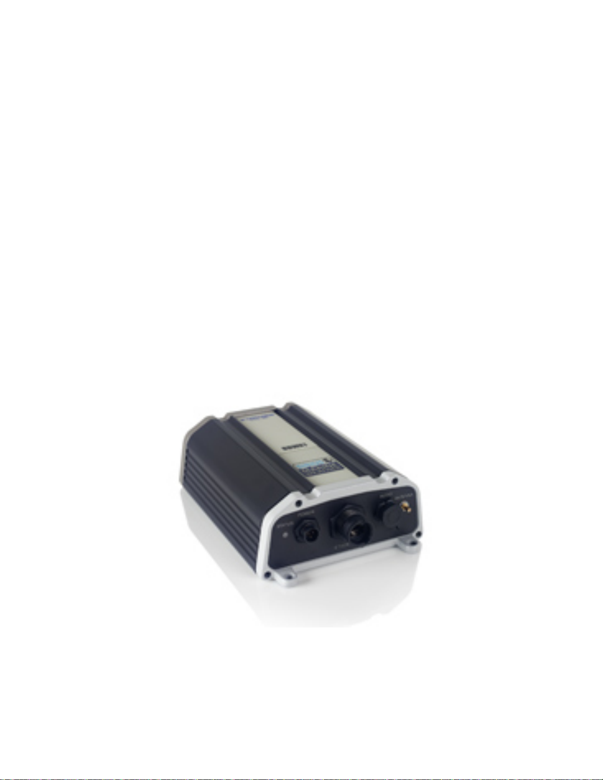
BBWX1 Satellite Weather
Receiver
Installation and Maintenance Guide
Page 2

Rev FUSA 15JUL2007
Table of Contents
Safety Precautions ………………………………………… 3
Disclaimer …………………………………………………. 3
Contents of Package …………………………….…………4
Tools Required …………………………………….……….4
Installation
General Precautions and Planning…………………5
Antenna Installation ……………………………...…6
Cable Installation ……………………………………9
BBWX1 Receiver Installation ………………………10
Typical System Diagrams ………………………………... 11
Activation ………………………………………………….. 12
Operation ………………………………………….……..….12
Troubleshooting - Diagnostics …………………………….13
General Maintenance ………………………………………14
2
Page 3

Safety Precautions:
• Ensure power is turned off before attempting to install your weather system or
carrying out routine maintenance.
• This system is NOT intended for use on “positive” ground vessels.
• Installation and operation of this equipment must be followed per these
instructions. Failure to comply could result in personal injury, damage to your
vessel and/ or poor product performance.
• This equipment is intended as an aid only. Standard boating precautions still
apply.
• Ensure a 2A slow blow fuse is fitted in the positive line [red wire] of the power
cord between the receiver and the power source [battery]. As close as possible to
the power source [battery] end.
Disclaimer:
CAUTION – ADVISORY ONLY
The weather information is subject to service interruptions and
may contain errors or inaccuracies and consequently should not
be relied upon exclusively. The service is provided as is. You
are urged to check alternate weather information sources prior
to making safety related decisions. You acknowledge and
agree that you shall be solely responsible for use of
the information and all decisions taken with respect thereto.
By using this service, you release and waive any claims against
Sirius Satellite Radio Inc., WSI, Navcast Incorporated, Furuno
with regard to this service.
If you do not have the subscription agreement, you will find a copy at:
www.sirius.com/marineweather/marineweather_terms_and_conditions.pdf
or call 1-800-869-5480 to have a copy sent to you.
3
Page 4

Contents of Package:
• BBWX1 Receiver Module
• SRA-40 Antenna Kit [includes 25 ft {7.6m} cable and mounting kit for various
thicknesses of mounting substrate].
• Power Cable 10 ft [3m]. 3 pin connector, 20 AWG 2 wire and shield.
• Ethernet Cable 10 ft [3m]
• Screws [3] #10 x 1” long, Type A, S/ T, ST/ST for mounting Antenna.
• Screws [3] #6 x 5/8” long, Type A, S/ T, ST/ST for mounting Receiver.
• Operator’s Guide
Tools Required:
• Drill
• Phillips screwdriver.
• 9/16” drill bit [centre hole for passing cable attached to the antenna base].
• 7/64” drill bit [3 mtg holes for antenna base].*
• #36 drill bit [3 mtg holes for receiver unit].*
• Pencil/ marker for marking location of holes.
* depending on thickness of mounti ng su bstrate, holes may be required to be enlarged.
4
Page 5

Installation:
General Precautions and Planning:
• Your vessels power system should be either:
Negative grounded, with the negative battery terminal connected to the vessels
ground, or floating with neither battery terminal connected to the vessels ground.
It is important that an effective RF ground is connected to your weather system –
if an RF system is installed.
• The receiver should not be installed in an environment outside of the following
temperatures: operating: 32 F to 131 F.
Storage: -31 F to 185 F.
• Do not place receiver close to the vessels engine or where fuel vapor may be
present.
• Do not place the receiver where water may be present [internal or spray from the
environment].
• Do not install receiver or antenna where it can be damaged by being kicked or
trampled.
• Area behind the mounting position of the receiver must be free and clear of cables
and obstructions.
• The antenna can be installed in either the “pedestal” mode [as supplied] or by
“surface mount” mode. See instructions under “antenna”.
• The antenna beam is required to have an unrestricted view of the skies; this
constitutes 5 ft [1.5m] out from the antenna and 1 ft [0.3m] above and below the
antenna.
• The antenna is to be installed on a flat horizontal surface.
• The antenna must not be installed in the path of a radar beam.
• Area below mounting position of antenna must be free and clear of cables and
obstructions.
• Avoid running cables through bilges or doorways or close to moving or “hot”
objects. Where a cable passes through an exposed bulkhead or deck head, a
watertight gland or “swan neck” tube should be used. Care to be taken “pulling”
cables and or connectors through bulkheads as damage could occur.
5
Page 6

• The power cable supplied is 10 ft [3m], however it can be extended up to 60 ft
[see power cable installation].
• The antenna cable supplied is 25 ft [7.6m], however alternative lengths can be
ordered [35 ft, 50 ft, 90 ft and 135 ft. Be advised that the 135 ft cable comes with
its own “inline amplifier”.
Mounting the Antenna:
• The antenna can be installed as a standard “pedestal” mounting or “surface”
mounting [non metallic surface only].
• Depending on the method of mounting and thickness of mounting substrate, the
hardware screws supplied may not be suitable.
• First determine the method of mounting to be used. For “pedestal” mounting it is
required to drill both the 9/16” hole and the three 7/64” dia. holes. For the “direct
surface mount” method, only the 9/16” dia. hole is required.
Pedestal mounting: [see fig. 1]
1. Unscrew the base from the lower plastic body [note the “O” ring and retain].
2. Use the rubber gasket or base as a template to mark the locations of the three
mounting holes and the centre hole for passing through the short antenna cable
with the connector.
3. Use the 9/16” drill bit for the centre hole and the 7/64” drill bit for the three fixing
holes.
4. Thread the short cable and connector through the gasket and centre hole.
5. Mount the gasket and flange of the antenna using the supplied screws.
6. Attach the antenna base to the lower body plastic, making sure the “O” ring is in
place.
Surface mounting: [FOR NON METALIC SUBSTRATES ONLY]. See fig. 2
& fig. 3.
There are two options available depending on location and mounting structure.
1. Up to ¼” thick mounting substrate.
2. ¼” – 1” thick mounting substrate.
• For substrates up to ¼” thick - only the 9/16” dia. hole is required.
6
Page 7

1. Remove the lower plastic body of the antenna [not the mounting base] and pass
the short cable with its connector through.
2. Seal the hole around the shaft passing through with a suitable weather sealer [not
supplied] before installing the lock washer and nut supplied.
• For substrates between ¼” to 1” thick - only the 9/16” dia. hole is required.
1. As above, remove the lower plastic body of the antenna.
2. The extension shaft is now required to be attached to the threaded metallic post of
the antenna, ensuring that the cable is first located in the slot of the threaded
metallic post.
3. This assembly can now be passed through the 9/16” hole and as above, seal before
installing the lock washer and nut.
Fig. 1
7
Page 8

Fig. 2
Fig. 3
8
Page 9

Cable Installation:
• The power cable, as supplied is 10 ft [3m] long, however it may be extended to a
maximum of 60 ft [20m] using a suitable 16 AWG multi stranded cable. Red is
positive, black is negative.
• Should the shield wire of the power cable be required to be extended to reach the
nearest ground point [RF ground preferred if installed on your vessel.] Use a 16
AWG multi strand wire. If your vessel does not have an RF system, connect the
shield wire to the negative battery terminal.
• The antenna cable, as supplied is 25 ft [7.6m]. Should it not be sufficient for
your installation, contact your dealer to obtain a suitable cable.
• The Ethernet cable, as supplied is 10 ft [3m] and is required to be connected
between the receiver and an ethernet hub. If you are connecting the BBWX1 to a
single Furuno VX2 processor / display, you must purchase an optional Furuno
Navnet Ethernet Cross-over cable and hub adapter cable, and an RJ-45 inline
coupler. Be advised that the hub, coupler and cross over cable are not supplied.
• GENERAL: All cables are to be secured properly over their entire length
with no strain on any connector. Furthermore the minimum bend radius to
be greater than 1” [25.4mm]. This applies when routing cables and/ or
bundling excess cable.
9
Page 10

BBWX1 Receiver:
• Important REMINDER: Record both the Sirius Data and Audio Serial
numbers as identified on the underside of your receiver before mounting.
• Orientation of the unit to be such that the connector panel is pointing down and
receiver be mounted on a vertical face.
• A minimum of 6” [152mm] is required to be left below the connector panel to
allow for adequate clearance for connections and cable bends.
1. Mark the location of the three fixing holes by using the unit as a template.
2. Drill through the marked positions using the #36 drill bit.
3. Mount the receiver using the three #6 x 5/8 lg type A, S/T screws supplied.
* depending on thickness of substrate the holes may require enlarging.
10
Page 11

Typical system Diagrams:
NavNet 6-Pin to 6-Pin Blue Network
Cable and Hub Adapater Cable
NavNet VX2
Display
NavNet 6-Pin to 6-Pin Blue Network
Cable and Hub Adapater Cable
NavNet VX2
Display
Ethernet
Hub
Dual Display / Processor
SRA-40
BBWX1
SRA-40
To connect a single NavNet display to a BBWX1, use 000-
146-289 cable and an RJ-45 to RJ-45 Inline coupler, or use a
standard NavNet Blue 6 pin to 6 pin network cable and a hub
adapter cable (000-144-463) w i th a cro ss-over RJ-45 to RJ-4 5
Inline Coupler.
RJ-45 Straight Through Inline
Coupler RJ4--5CN-STR
000-146-289 5 meter 6 pin to RJ-45 Cable
NavNet VX2
NavNet 6-Pin to 6-Pin
Blue Network Cable
OR
and Hub Adapter Cable
RJ-45 Crossover
Inline Coupler P/N
RJ4-5CN-CRS
BBWX1 Ethernet
Cable (std supply)
BBWX1
Display
Single Display / Processor (optional NavNet cable(s) and coupler required)
11
Page 12

Initial Activation:
1. Power the receiver and confirm solid red LED for approx. 1 minute. This is
followed by a solid amber to flashing amber to solid green to finally a flashing
green LED [additional 0.5 minutes]. At this point the software is fully loaded and
system is ready.
2. Turn on your display [refer to your individual user guide/ handbook for detailed
information].
3. Contact Sirius to “activate” your system. (1-800-869-5480)
Reminder: have your serial number available (Data ESN) which is
marked on the underside of your receiver. Note: Should you see
actual weather data displayed prior to “activation”, this is only
the balance of the manufacturers [time limited activation which
was used for testing purposes at the factory] and does not reflect
that your personal “activation” is in place.
Operation:
1. With the system and your display powered ON.
2. It may take up to 30 minutes before the system is populated with weather data.
3. Open a weather application page on your display and make it active. [For full
details of how to carry this out, refer to the relevant display handbook supplied
with your equipment.]
4. One of your first actions will be to locate and record your own personal Sirius ID
number.
12
Page 13

Troubleshooting.
BBWX1 Diagnostics:
1. The following identifies the “Key” to the LED blinking pattern as depicted on the
connector panel of the receiver.
KEY.
FAULT LED COLOR PATTERN
Network disconnected: Amber 1 sec. ON
1 sec. OFF
1 sec. ON
2 sec. OFF
Antenna disconnected: Amber 1 sec. ON
2 sec. OFF
Both disconnected: Amber 1 sec. ON
1 sec. OFF
1 sec. ON
2 sec. OFF
1 sec. ON
2 sec. OFF
System Ready: Green Flashing
13
Page 14

GENERAL MAINTENANCE:
• Caution: Always turn your weather system OFF before carrying out routine
maintenance.
• Your SDR is a sealed unit. DO NOT REMOVE the two end plates of the
receiver. There are no user serviceable parts or adjustments inside. Any internal
adjustments to be made must be carried out by an approved and qualified
technician.
Routine checks:
• Examine all cables for signs of damage.
• Check that all cables are supported.
• Check that all connectors are fully inserted and supported.
• Check that dust caps are located on the connector face [if no cable is available].
Cleaning:
• Wipe the module with a clean damp cloth.
• If necessary, Isopropyl Alcohol [IPA] or a mild detergent
remove stubborn marks.
solution can be used to
14
 Loading...