

Page 1

OPERATOR'S MANUAL
GPS NAVIGATOR
Model
GP-170
www.furuno.com
Page 2

The paper used in this manual
9-52 Ashihara-cho,
A:JUN
2014
.
Pub. No.
(
)
Nishinomiya, 662-8580, JAPAN
is elemental chlorine free.
・FURUNO Authorized Distributor/Dealer
All rights reserved.
YOTA
GP-170
Printed in Japan
OME-44820-A
0 0 0 1 7 7 7 3 6 1 0
Page 3

IMPORTANT NOTICE
General
• This manual has been authored with simplified grammar, to meet the needs of international users.
• The operator of this equipment must read and follow the descriptions in this manual. Wrong operation or maintenance can cancel the warranty or cause injury.
• Do not copy any part of this manual without written permission from FURUNO.
• If this manual is lost or worn, contact your dealer about replacement.
• The contents of this manual and equipment specifications can change without notice.
• The example screens (or illustrations) shown in this manual can be different from the screens
you see on your display. The screens you see depend on your system configuration and equipment settings.
• Save this manual for future reference.
• Any modification of the equipment (including software) by persons not authorized by FURUNO
will cancel the warranty.
• All brand and product names are trademarks, registered trademarks or service marks of their
respective holders.
How to discard this product
Discard this product according to local regulations for the disposal of industrial waste. For disposal
in the USA, see the homepage of the Electronics Industries Alliance (http://www.eiae.org/) for the
correct method of disposal.
How to discard a used battery
Some FURUNO products have a battery(ies). To see if your product has a battery(ies), see the
chapter on Maintenance. Follow the instructions below if a battery(ies) is used. Tape the + and terminals of battery before disposal to prevent fire, heat generation caused by short circuit.
In the European Union
The crossed-out trash can symbol indicates that all types of batteries
must not be discarded in standard trash, or at a trash site. Take the
used batteries to a battery collection site according to your national
legislation and the Batteries Directive 2006/66/EU.
In the USA
The Mobius loop symbol (three chasing arrows) indicates that Ni-Cd
and lead-acid rechargeable batteries must be recycled. Take the
used batteries to a battery collection site according to local laws.
In the other countries
Ni-Cd Pb
Cd
There are no international standards for the battery recycle symbol. The number of symbols can
increase when the other countries make their own recycle symbols in the future.
i
Page 4
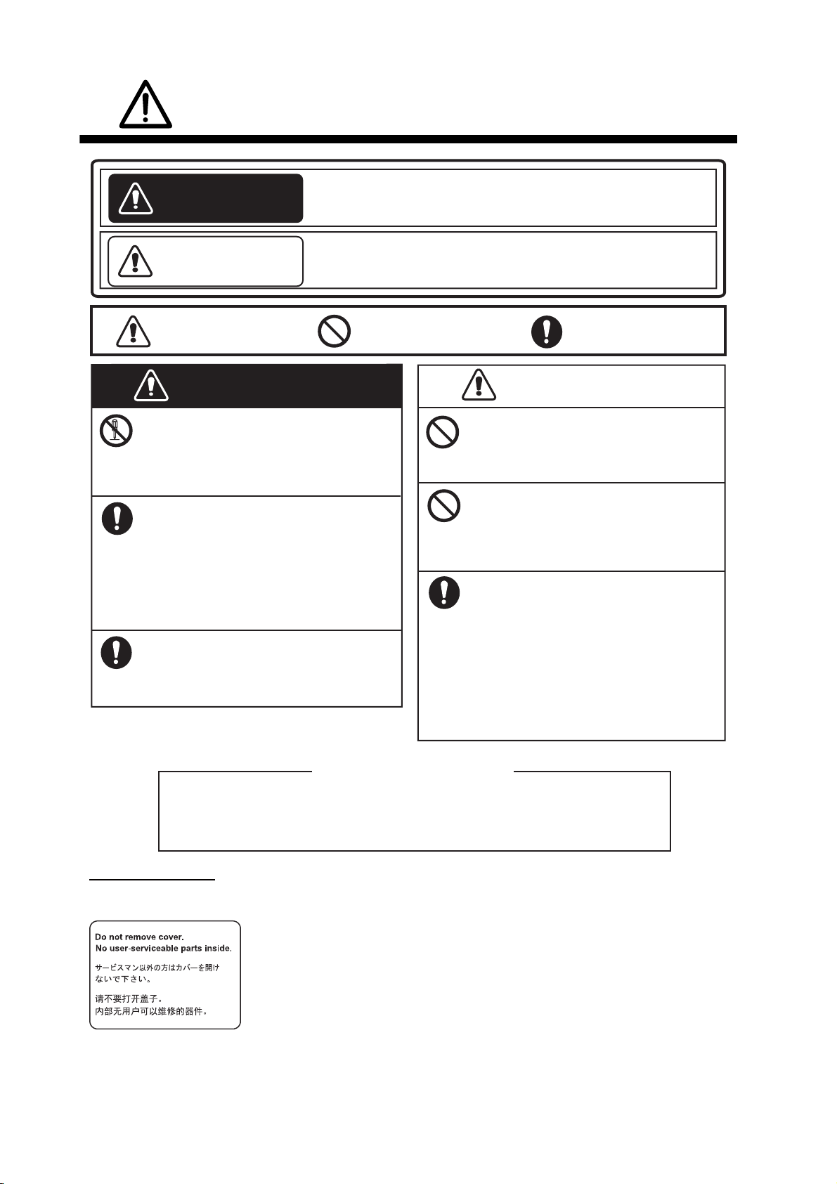
SAFETY INSTRUCTIONS
WARNING
CAUTION
Indicates a condition that can cause death or serious
injury if not avoided.
Indicates a condition that can cause minor or moderate
injury if not avoided.
Warning, Caution Prohibitive Action Mandatory Action
WARNING
Do not disassemble or modify
the equipment.
Fire, electrical shock or serious
injury can occur.
Turn off the power immediately if
water leaks into the equipment or
smoke or fire is coming from the
equipment.
Failure to turn off the equipment can
cause fire or electrical shock.
Contact a FURUNO agent for service.
Use the correct fuse.
A wrong fuse can cause fire or serious
damage to the equipment.
CAUTION
The glass of an LCD panel breaks
easily. Handle the LCD carefully.
Injury can result if the glass breaks.
Do not connect/disconnect the
signal cable while turning the
power on.
The unit may be damaged.
No single navigation aid (including
this unit) should ever be relied
upon as the exclusive means for
navigating your vessel.
The navigator is responsible for
checking all aids available to confirm
his position. Electronic aids are
intended to assist, not replace, the
navigator.
About the TFT LCD
The TFT LCD is constructed using the latest LCD techniques, and displays
99.99% of its pixels. The remaining 0.01% of the pixels may drop out or
blink, however this is not an indication of malfunction.
Caution Label(s)
Caution label(s) is(are) attached to the equipment. Do not remove the label(s). If a label is missing or
damaged, contact a FURUNO agent or dealer about replacement.
Name: Caution Label
Type: 20-035-1003-0
Code No.: 100-386-200-10
ii
Page 5

TABLE OF CONTENTS
FOREWORD...................................................................................................................vi
SYSTEM CONFIGURATIONS....................................................................................... vii
1. OPERATIONAL OVERVIEW.................................................................................1-1
1.1 Controls ......................................................................................................................1-1
1.2 How to Turn the Power On/Off ...................................................................................1-3
1.3 How to Adjust the Brilliance of the Display and Panel................................................1-4
1.4 How to Select the Display Mode.................................................................................1-5
1.5 Main Menu Overview..................................................................................................1-8
1.6 List Overview ..............................................................................................................1-9
1.7 Context Menu Overview ...........................................................................................1-10
2. PLOTTER DISPLAY OVERVIEW, TRACK ...........................................................2-1
2.1 How to Set the Display ...............................................................................................2-1
2.1.1 How to select the background color ...............................................................2-1
2.1.2 How to zoom in or out the display ..................................................................2-1
2.1.3 How to change the display orientation ...........................................................2-1
2.1.4 How to turn the cursor on/off, change cursor size..........................................2-2
2.1.5 How to move the cursor .................................................................................2-2
2.1.6 How to shift the display ..................................................................................2-2
2.1.7 How to center the cursor position or ship's position .......................................2-3
2.1.8 How to show or hide the grid and change its color.........................................2-3
2.1.9 How to show or hide the XTL line and change its color .................................2-3
2.1.10 How to show or hide the heading line and change its color ...........................2-4
2.1.11 How to set the COG vector ............................................................................2-4
2.1.12 How to display the time mark .........................................................................2-5
2.1.13 How to display the names for marks and waypoints ......................................2-5
2.1.14 How to show or hide the weather data ...........................................................2-5
2.2 Bearing Reference......................................................................................................2-6
2.2.1 How to select bearing reference.....................................................................2-6
2.2.2 How to set the magnetic variation ..................................................................2-6
2.3 About Tracks ..............................................................................................................2-7
2.3.1 How to start or stop plotting and recording of the track..................................2-7
2.3.2 How to set the track plotting interval ..............................................................2-7
2.3.3 How to set the track color ...............................................................................2-8
2.3.4 How to erase the track ...................................................................................2-8
3. MARKS ..................................................................................................................3-1
3.1 How to Enter a Mark on the Plotter Display................................................................3-1
3.1.1 How to preset mark appearance ....................................................................3-1
3.1.2 How to enter a mark at the cursor position.....................................................3-2
3.1.3 How to enter a mark from the mark list ..........................................................3-2
3.2 How to Enter an Event Mark.......................................................................................3-5
3.2.1 How to preset event mark appearance ..........................................................3-5
3.2.2 How to enter an event mark at own ship’s position ........................................3-5
3.2.3 How to enter an event mark from the mark list...............................................3-5
3.3 How to Enter a MOB Mark on the Plotter Display ......................................................3-6
3.4 How to Edit a Mark or an Event Mark .........................................................................3-7
3.5 How to Erase Marks ...................................................................................................3-8
4. ROUTES ................................................................................................................ 4-1
4.1 How to Create a Route ...............................................................................................4-1
iii
Page 6

TABLE OF CONTENTS
4.1.1 How to preset the settings for routes ............................................................. 4-1
4.1.2 How to create a new route with the cursor and the ROUTE key....................4-3
4.1.3 How to create a new route from the route list ................................................ 4-4
4.2 How to Edit a Route ................................................................................................... 4-6
4.2.1 How to change the route name or color.........................................................4-6
4.2.2 How to edit a waypoint in a route ................................................................... 4-7
4.2.3 How to temporarily deselect a waypoint in a route......................................... 4-8
4.2.4 How to delete a waypoint from a route........................................................... 4-9
4.2.5 How to insert a waypoint in a route .............................................................. 4-10
4.2.6 How to change the route direction ...............................................................4-11
4.2.7 How to copy the route .................................................................................. 4-11
4.3 How to Erase a Route .............................................................................................. 4-12
5. DESTINATION .......................................................................................................5-1
5.1 How to Set a Destination............................................................................................ 5-1
5.1.1 How to set a cursor position as a destination................................................. 5-1
5.1.2 How to set a waypoint as a destination.......................................................... 5-1
5.1.3 How to set a registered mark as a destination ............................................... 5-2
5.1.4 How to set a registered route as a destination............................................... 5-3
5.2 How to Cancel a Destination...................................................................................... 5-3
5.2.1 How to cancel a destination with the GO TO key........................................... 5-3
5.2.2 How to cancel a destination from the main menu .......................................... 5-3
5.2.3 How to cancel a destination from the context menu ...................................... 5-4
5.3 How to Calculate the Distance, Bearing and TTG (Time To Go)
Between Two Points .................................................................................................. 5-4
5.4 How to Display the ETA and TTG.............................................................................. 5-5
5.5 How to Calculate the Trip Distance ............................................................................ 5-6
5.6 How to Set the Drift .................................................................................................... 5-6
6. NOTICES................................................................................................................6-1
6.1 Audio Notice Type...................................................................................................... 6-1
6.2 Arrival/Anchor Notice ................................................................................................. 6-2
6.2.1 Arrival notice .................................................................................................. 6-2
6.2.2 Anchor notice ................................................................................................. 6-2
6.3 XTE Notice ................................................................................................................. 6-3
6.4 Ship Speed Notice ..................................................................................................... 6-3
6.5 Trip Notice ..................................................................................................................6-4
7. DISPLAYS..............................................................................................................7-1
7.1 Integrity Display.......................................................................................................... 7-1
7.2 Highway Display......................................................................................................... 7-4
7.3 Course Display........................................................................................................... 7-5
7.4 Data Display ............................................................................................................... 7-6
8. ALERTS .................................................................................................................8-1
8.1 Overview .................................................................................................................... 8-1
8.2 Alert List ..................................................................................................................... 8-3
8.3 Alert Log ..................................................................................................................... 8-4
8.4 How to Acknowledge Alerts ....................................................................................... 8-4
9. OTHER FUNCTIONS .............................................................................................9-1
9.1 Unit Setup Menu ........................................................................................................ 9-1
9.2 Correction, Offset Menu ............................................................................................. 9-1
9.3 GNSS Menu ............................................................................................................... 9-4
9.3.1 How to select the positioning system ............................................................. 9-4
9.3.2 How to set the time for smoothing of position, speed and speed average.....9-4
iv
Page 7

TABLE OF CONTENTS
9.3.3 How to set the positioning condition ...............................................................9-5
9.3.4 How to select the RAIM function ....................................................................9-6
9.3.5 How to select the datum.................................................................................9-7
9.3.6 How to set the initial position ..........................................................................9-7
9.3.7 How to set the positioning cycle .....................................................................9-8
9.3.8 How to turn the anti-multipath mode on/off ....................................................9-8
9.4 Beacon/SBAS Menu...................................................................................................9-9
9.4.1 How to select the differential corrections to use .............................................9-9
9.4.2 How to set SBAS and beacon ........................................................................9-9
9.4.3 How to open the station data........................................................................9-10
9.5 Language..................................................................................................................9-12
9.6 I/O Menu...................................................................................................................9-13
9.6.1 How to set the output 1, 2, 3 or 4 .................................................................9-13
9.6.2 How to set the Ethernet................................................................................9-14
9.6.3 How to select the input data.........................................................................9-15
9.6.4 Line monitor log............................................................................................9-16
9.7 How to Set Dual Configuration .................................................................................9-18
9.8 How to Set ECDIS Sync Configuration.....................................................................9-18
9.9 How to Change the User Password .........................................................................9-19
9.10 How to Set the Demo Mode .....................................................................................9-20
10. MAINTENANCE, TROUBLESHOOTING ...........................................................10-1
10.1 Maintenance .............................................................................................................10-1
10.2 Fuse Replacement ...................................................................................................10-2
10.3 Troubleshooting........................................................................................................10-2
10.4 Equipment Information .............................................................................................10-3
10.5 Self Test ...................................................................................................................10-4
10.6 Backup......................................................................................................................10-6
10.7 How to Clear the Memory.........................................................................................10-8
APPENDIX 1 MENU TREE .......................................................................................AP-1
APPENDIX 2 LIST OF TERMS/SYMBOLS ..............................................................AP-5
APPENDIX 3 TIME DIFFERENCES .........................................................................AP-9
APPENDIX 4 GEODETIC CHART LIST .................................................................AP-10
APPENDIX 5 WHAT IS SBAS?..............................................................................AP-11
APPENDIX 6 PARTS LIST/LOCATION..................................................................AP-12
SPECIFICATIONS ..................................................................................................... SP-1
INDEX ......................................................................................................................... IN-1
v
Page 8

FOREWORD
A Word to the Owner of the GP-170
Congratulations on your choice of the FURUNO GP-170 GPS Navigator. We are confident you
will see why the FURUNO name has become synonymous with quality and reliability.
Since 1948, FURUNO Electric Company has enjoyed an enviable reputation for innovative and
dependable marine electronics equipment. This dedication to excellence is furthered by our extensive global network of agents and dealers.
Your equipment is designed and constructed to meet the rigorous demands of the marine environment. However, no machine can perform its intended function unless properly installed and
maintained. Please carefully read and follow the operation and maintenance procedures set forth
in this manual.
We would appreciate feedback from you, the end-user, about where we are achieving our purposes.
Thank you for considering and purchasing FURUNO equipment.
Features
The main features of the GP-170 are as shown below.
• High-resolution color LCD
• Comprehensive navigation data displays
• A DGPS beacon receiver (internal or external) can be connected to the GP-170 to add DGPS
capability.
• Storage for 1,000 waypoints, 100 routes (99 for creating, one for external input), 1,000 tracks
and 2,000 marks
• External USB flash memory capability
• Notices: Arrival/Anchor, XTE (Cross-track Error), Ship speed, Trip
• Alerts: Warning, Caution
• Man overboard feature records position at time of man overboard and provides continuous updates of range and bearing when navigating to the MOB position.
• Unique Highway display provides a graphic presentation of ship’s progress toward a waypoint.
• User-programmable nav data displays provide digital navigation data.
• Two dual differential GPS navigator systems are available.
• Ethernet port for connection to a LAN
Program No.
MAIN: 2051542-01.XX, GPS: 48504650XX,
BEACON: 2051544-01.XX (Requires internal beacon receiver.)
XX: Minor change
Open Source Acknowledgement
This product makes use of the following open source software:
b64: Base-64 Encoding Library (http://synesis.com.au/software/b64.html)
Portions of this software are copyright 2012 Synesis Software Pty Ltd. All rights reserved.
C
vi
Page 9
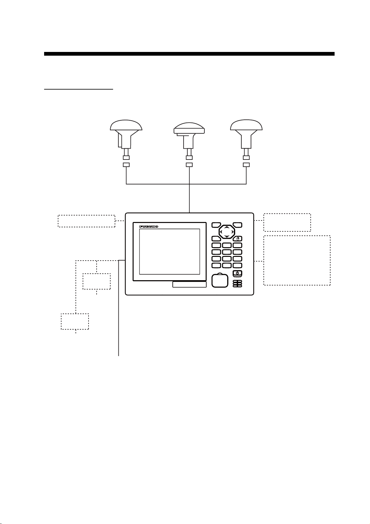
SYSTEM CONFIGURATIONS
Basic configuration is shown with solid line.
Single configuration
USB Flash Memory
Rectifier
PR-62
Antenna Unit
GPA-021S*
Antenna Unit
GPA-020S**
Antenna Unit
GPA-017S**
MENU
ESC
LIST
ROUTE
DISPLAY
12
MARK
MOB
EVENT
4
5
ZOOM
CENTER
78
IN
ACK
CURSOR
ON/OFF
0
DELETE
*: w/internal beacon receiver
**: w/o internal beacon receiver
NU/CU
GO TO
PLOT
ON/OFF
ZOOM
OUT
BRILL
ENT
3
6
9
Switching Hub
HUB-100
Radar,
Echo Sounder,
Autopilot,
Printer (PP-505FP),
Beacon Receiver,
Interface Unit IF-2503
110/220 VAC
Rectifier
PR-240
100 to 115/
200 to 230 VAC
Display Unit
12-24 VDC
vii
Page 10
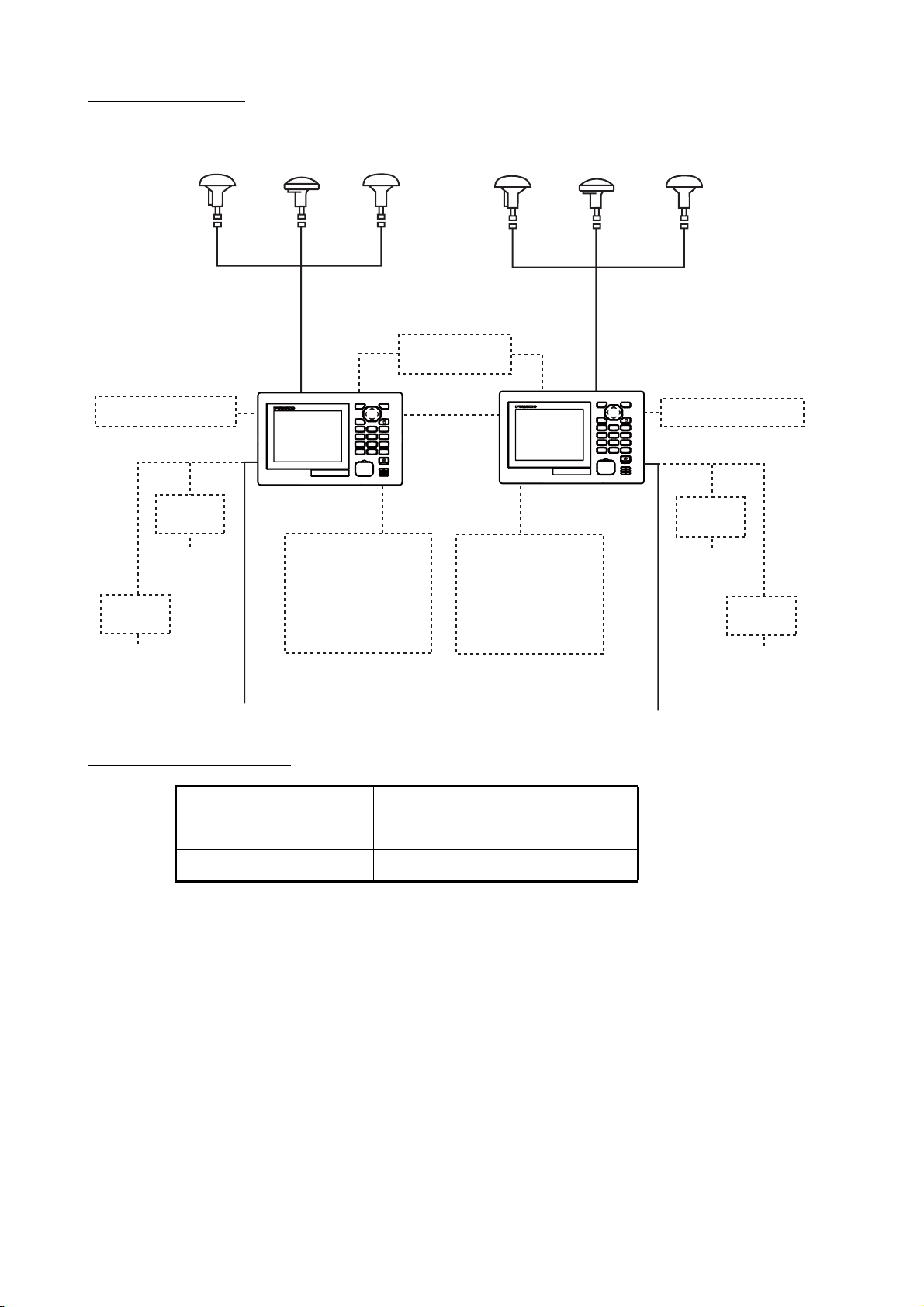
SYSTEM CONFIGURATIONS
Dual configuration
Antenna Unit
GPA-021S*
USB Flash Memory
Rectifier
PR-62
110/220 VAC
Rectifier
PR-240
100 to 115/
200 to 230 VAC
Antenna Unit
GPA-020S**
Antenna Unit
GPA-017S**
*: w/internal beacon receiver
**: w/o internal beacon receiver
MENU
ESC
LIST
DISPLAY
12
MOB
4
ZOOM
78
IN
ACK
DELETE
Display Unit
Radar,
Echo Sounder,
Autopilot,
Printer (PP-505FP),
Beacon Receiver,
Interface Unit IF-2503
Switching Hub
HUB-100
NU/CU
ENT
ROUTE
GO TO
3
MARK
PLOT
ON/OFF
EVENT
6
5
ZOOM
CENTER
9
OUT
CURSOR
BRILL
ON/OFF
0
Antenna Unit
GPA-021S*
Antenna Unit
GPA-020S**
MENU
ESC
LIST
DISPLAY
MOB
ZOOM
IN
ACK
DELETE
Display Unit
Radar,
Echo Sounder,
Autopilot,
Printer (PP-505FP),
Beacon Receiver,
Interface Unit IF-2503
ROUTE
12
MARK
EVENT
4
CENTER
78
CURSOR
ON/OFF
Antenna Unit
GPA-017S**
NU/CU
ENT
USB Flash Memory
GO TO
3
PLOT
ON/OFF
6
5
ZOOM
9
OUT
BRILL
0
Rectifier
PR-62
110/220 VAC
Rectifier
PR-240
100 to 115/
200 to 230 VAC
12-24 VDC
Environmental category
Units Category
Antenna Unit Exposed to the weather
Display Unit Protected from the weather
12-24 VDC
viii
Page 11
1. OPERATIONAL OVERVIEW
10
18
1
3
4
2
5
6
7
8
9
11
12
13
14
16
17
19
15
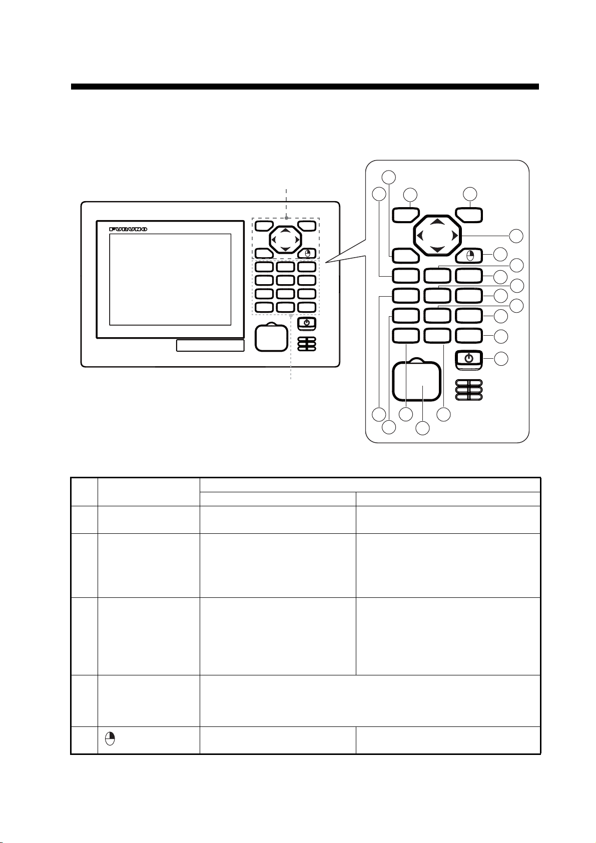
1.1 Controls
Operation keys
ROUTE
MARK
EVENT
CENTER
CURSOR
ON/OFF
NU/CU
ENT
GO TO
3
PLOT
ON/OFF
6
5
ZOOM
9
OUT
BRILL
0
MENU
ESC
LIST
DISPLAY
12
MOB
4
ZOOM
78
IN
ACK
DELETE
Function keys
The keys are arranged according to the function.
4
6
1
MENU
ESC
2
NU/CU
ENT
3
LIST
DISPLAY
MOB
ZOOM
IN
DELETE
ROUTE
12
MARK
EVENT
4
CENTER
78
ACK
CURSOR
ON/OFF
GO TO
PLOT
ON/OFF
5
ZOOM
OUT
BRILL
0
5
7
3
8
10
11
6
13
14
9
17
18
9
16
12
15
19
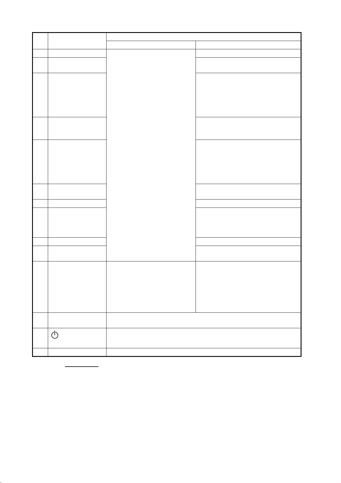
No. Control
Menu screen Display mode
1 MENU/ESC • Closes the menu.
• Quits current operation.
Function
• Opens the menu.
• Quits current operation.
2 NU/CU ENT Confirms a selection. • Switches the orientation mode
between north-up and course-up
on the plotter display.
3 Cursorpad • S or T: Selects the menu
item.
• W: Goes back one layer in
multi-layer menu.
• X: Goes forward one layer in
multi-layer menu.
4 LIST • Opens the list.
• Switches the list (any display → mark list → route list → station list
(requires the internal beacon receiver) → any display). Long-press to
switch the list in reverse order.
5
– Opens the context menu on the plotter
(Right-click)
• Confirms a selection then closes
the setting window.
• Shifts display or cursor on the
plotter display.
• Switches display on the integrity
display.
display.
1-1
Page 12
1. OPERATIONAL OVERVIEW
No. Control
6 DISPLAY/1 • Selects and confirms the
7 ROUTE/2 Starts/stops the registration of a route
• Enters a numeric character.
8 GO TO/3 • Sets a destination at the cursor
9 MOB/4 Marks a man overboard position and
10 MARK EVENT/5 • Puts a mark at the cursor position
11 PLOT ON/OFF/
6
12 ZOOM IN/7 Zooms in the plotter display.
13 CENTER/8 • Centers the cursor position on the
14 ZOOM OUT/9 Zooms out the plotter display.
15 CURSOR ON/OFF/
0
16 ACK/DELETE • Acknowledges an
• Deletes all setting values on
17 BRILL Opens the brilliance adjustment window.
Adjusts the display brilliance when the adjustment window opens.
18
19 USB port For connection of USB flash memory.
(Power)
Turns the power on or off.
Menu screen Display mode
selected menu item.
unacknowledged alert when
the pop-up appears.
the setting window when
there is no unacknowledged
alerts.
Function
Selects the display mode.
on the plotter display.
position on the plotter display with
cursor on.
• Opens the context menu for Go To
on the plotter display with cursor
off.
sets a destination on the plotter
display.
on the plotter display with cursor
on.
• Puts an event mark at own ship’s
position on the plotter display with
cursor off.
Resumes/stops track plotting on the
plotter display.
plotter display with cursor on.
• Centers own ship’s position on the
plotter display with cursor off.
Turns the cursor on or off on the
plotter display.
• Acknowledges an unacknowledged
alert when the pop-up appears.
• Deletes registered data (marks,
etc.) at the cursor-selected position
on the plotter display when there
are no unacknowledged alerts.
1-2
Key sound
When you operate a key, a single beep sounds. If you do not need the key beep, deactivate the beep sound as follows (see section 1.5):
1. Press the MENU/ESC key to open the main menu.
2. Select [4 Notice Setting] then [9 Sound].
3. Select [2 Key Sound].
4. Select [2 Off].
5. Press the MENU/ESC key to close the main menu.
Page 13
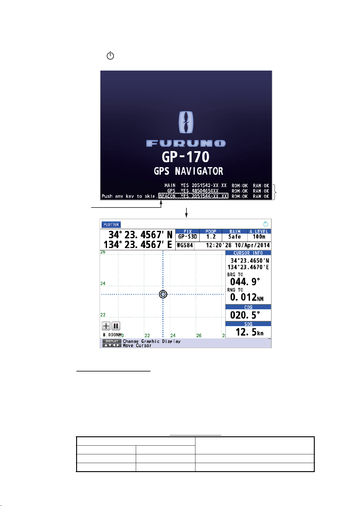
1.2 How to Turn the Power On/Off
A
Press the key to turn the power on. The start-up screen appears for 30 seconds
then the last-used screen appears.
ppears when
internal beacon
receiver is installed.
Start-up screen
XX: Program version numbers
1. OPERATIONAL OVERVIEW
Self test
results
Last-used screen (example: plotter display)
DGPS beacon receiver
The GP-170 is available in two specifications, with DGPS beacon receiver and no
DGPS beacon receiver. Only the beacon receiver equipped GP-170 has DGPS capability. To get DGPS capability, install the optional internal beacon receiver (name: beacon receiver set, type: OP20-42, code no.: 000-023-637) or connect an external
beacon receiver.
Status indications
Indication
2D positioning 3D positioning
GP-2D GP-3D GPS
GP-S2D GP-S3D GPS + SBAS
System
1-3
Page 14
1. OPERATIONAL OVERVIEW
Indication
2D positioning 3D positioning
GP-D2D GP-D3D GPS + Differential
GP-D2D (Yellow) GP-D3D (Yellow) GPS + Differential (WER>10%)
GP-D2D! (Yellow) GP-D3D! (Yellow) GPS + Differential (Unmonitored)
GA-2D GA-3D GALILEO
GA-S2D GA-S3D GALILEO + SBAS
GA-D2D GA-D3D GALILEO + Differential
GA-D2D (Yellow) GA-D3D (Yellow) GALILEO + Differential (WER>10%)
GA-D2D! (Yellow) GA-D3D! (Yellow) GALILEO + Differential (Unmonitored)
GL-2D GL-3D GLONASS
GL-S2D GL-S3D GLONASS + SBAS
GL-D2D GL-D3D GLONASS + Differential
GL-D2D (Yellow) GL-D3D (Yellow) GLONASS + Differential (WER>10%)
GL-D2D! (Yellow) GL-D3D! (Yellow) GLONASS + Differential (Unmonitored)
GN-2D GN-3D Multi
GN-S2D GN-S3D Multi + SBAS
GN-D2D GN-D3D Multi + Differential
GN-D2D (Yellow) GN-D3D (Yellow) Multi + Differential (WER>10%)
GN-D2D! (Yellow) GN-D3D! (Yellow) Multi + Differential (Unmonitored)
No Fix No fixed
System
2D positioning: Three satellites are used.
3D positioning: More than four satellites are used.
Note 1: GLONASS, GALILEO and Multi are reserved for future use.
Note 2: The screen refreshes slower in low ambient temperature.
To turn the power off, press the key.
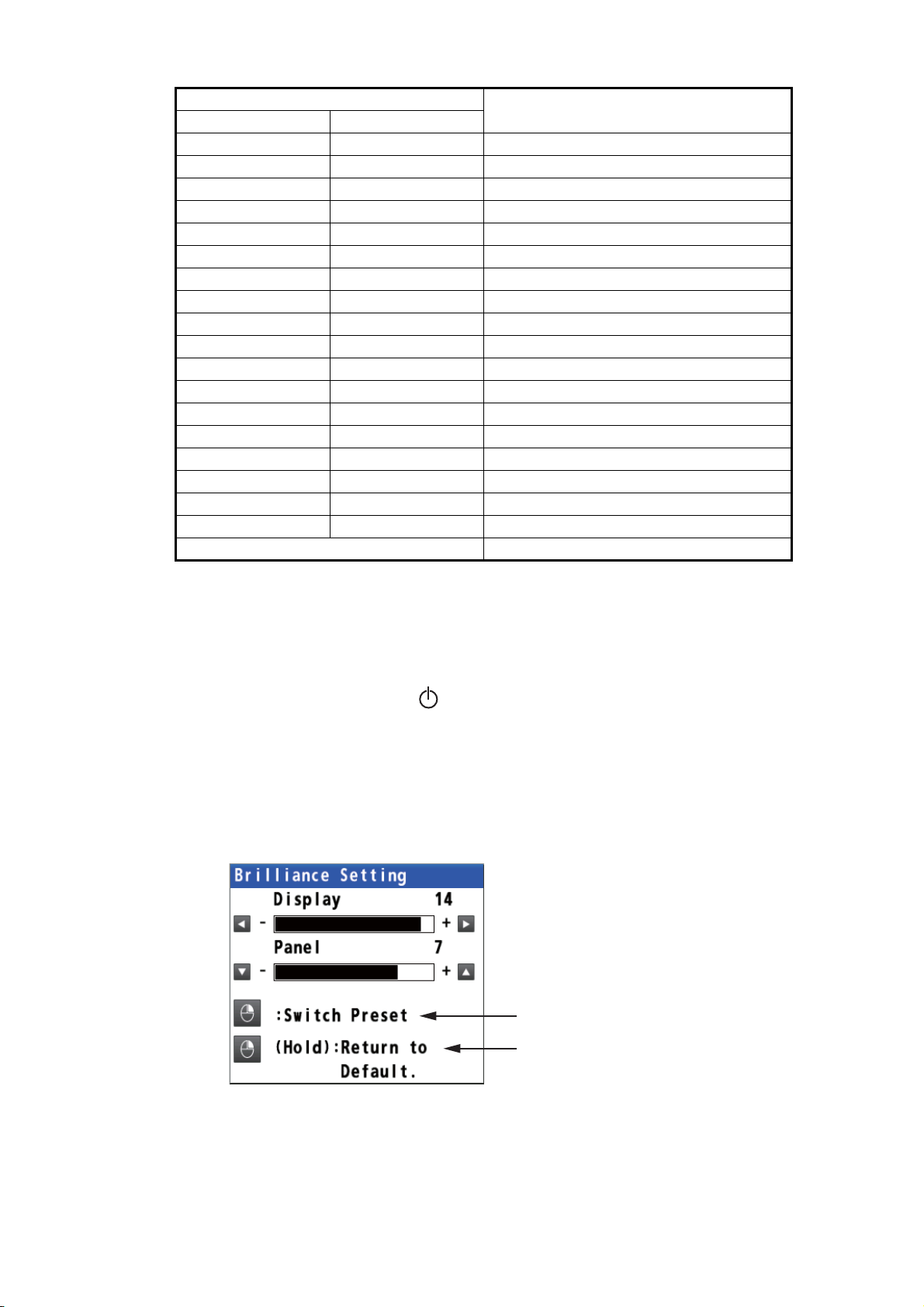
1.3 How to Adjust the Brilliance of the Display and Panel
1. Press the BRILL key to show the following setting window.
Switch the color mode between
day mode and night mode.
Long-press to restore the
settings to default of day mode.
1-4
2. To adjust the display brilliance, use the cursorpad (W or X) or the BRILL key (set-
ting range: 0 to 15, default: 14 for day mode/6 for night mode).
3. To adjust the panel brilliance, use the cursorpad (S or T) (setting range: 0 to 9,
default: 7 for day and night modes).
4. Press the MENU/ESC key to close the setting window.
Page 15
Note 1: The default settings for night mode is 6 for [Display] and 7 for [Panel]. If the
display is difficult to see when switching to the night mode, use the cursorpad (X) to
increase the display brilliance.
Note 2: Whenever the brilliance mode is changed, the last-used brilliance for the selected mode is set.
Note 3: When the brilliance is preset, the background color is also preset (see
paragraph 2.1.1). So both the brilliance and the background color are restored to the
default when long-pressing the key.
1.4 How to Select the Display Mode
There are five display modes: PLOTTER, INTEGRITY, HIGHWAY, COURSE and DATA. Press the DISPLAY key to select the display mode, in the following sequence. To
reverse the order, long-press the DISPLAY key.
1. OPERATIONAL OVERVIEW
Mode
PLOTTER INTEGRITY HIGHWAY
: Short-press the DISPLAY key
: Long-press the DISPLAY key
COURSEDATA
You can turn off the highway, course or data display if its use is not required.
1. Press the MENU/ESC key to open the main menu.
2. Select [1 Display] then [9 Display Select].
3. Select [3 Highway], [4 Course] or [5 Data].
4. Select [1 On] or [2 Off]. The display modes which are set to off are skipped when
operating the DISPLAY key.
Note: The plotter and integrity displays can not be disabled.
5. Press the MENU/ESC key to close the main menu.
The data is arranged according to data type.
Common information
*: The alert information is displayed when an alert occurs.
Main information
Guidance or
alert information*
1-5
Page 16
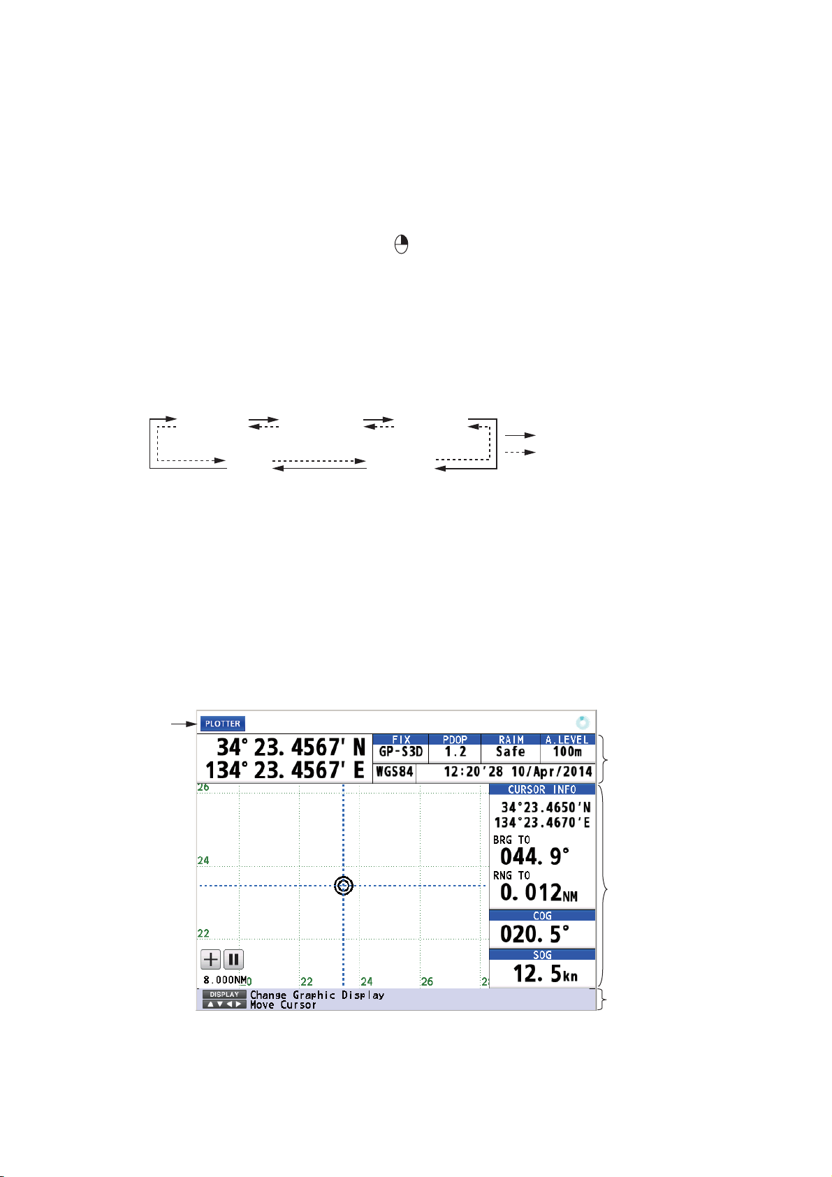
1. OPERATIONAL OVERVIEW
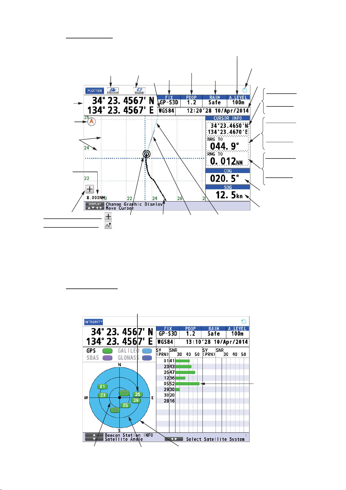
Plotter Display
This icon appears when the number
of satellites used for positioning is
more than four and the high precision speed computing is available.
Ship’s
position*
North
mark
Grid
Range
scale
Cursor on (Cursor mode):
Cursor off (Chart mode):
*: Shows the ship’s position adjusted with the setting position offset based
on the selected datum (refer to paragraph 9.3.5).
Ship’s mark Course bar
This icon appears
during the
synchronization
with ECDIS.
Datum
Status
indication
Ship’s track
Distance for RAIM reliability
HDOP: 2D
PDOP: 3D
RAIM reliability
Heading line
Spinner rotates when
the equipment is
functioning normally.
Time and date of
Position FIX
Cursor mode:
Cursor position,
Chart mode:
No indication
Cursor mode:
Bearing from
ship to cursor,
Chart mode:
Bearing
Cursor mode:
Range from
ship to cursor,
Chart mode:
Range
Course over
ground
Speed over
ground
Note: The color of the ship’s position data depends on positioning status.
Black: GPS position fix
Red: No GPS position fix
Integrity Display
Satellites used for positioning (Satellite numbers used for positioning
are displayed in white, or black if not used for positioning.)
Receiver
signal level
(Bars show
signal level.)
1-6
Elevation 60° Elevation 30° Elevation 0°
Page 17
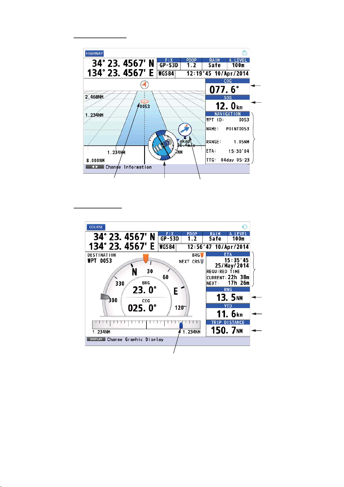
Highway Display
1. OPERATIONAL OVERVIEW
Course over
ground
Speed over
ground
Course
information
Waypoint
Course Display
Attitude gauge
Weather data
Estimated
time and date
of arrival
Range
Velocity to
destination
Trip distance
Cross track distance indication
1-7
Page 18
1. OPERATIONAL OVERVIEW
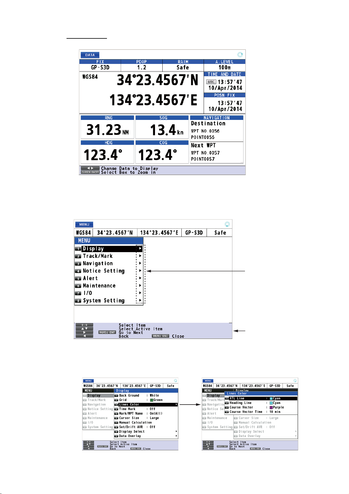
Data Display
Note: When invalid
data is input, “- - - -”
is displayed.
1.5 Main Menu Overview
1. Press the MENU/ESC key to open the main menu.
2. Use the cursorpad (S or T) to select a menu item then press the NU/CU ENT
key. You can also select a menu item by pressing the numeric keys. This manual
states this operating procedure as “Select [No. menu name].” The menu items that
have a X indicate additional menus.
These marks indicate
additional menus.
Basic operation or
alert information
1-8
Second layer
Third layer
Page 19
3. Select an option.
4. Press the MENU/ESC key to close the main menu.
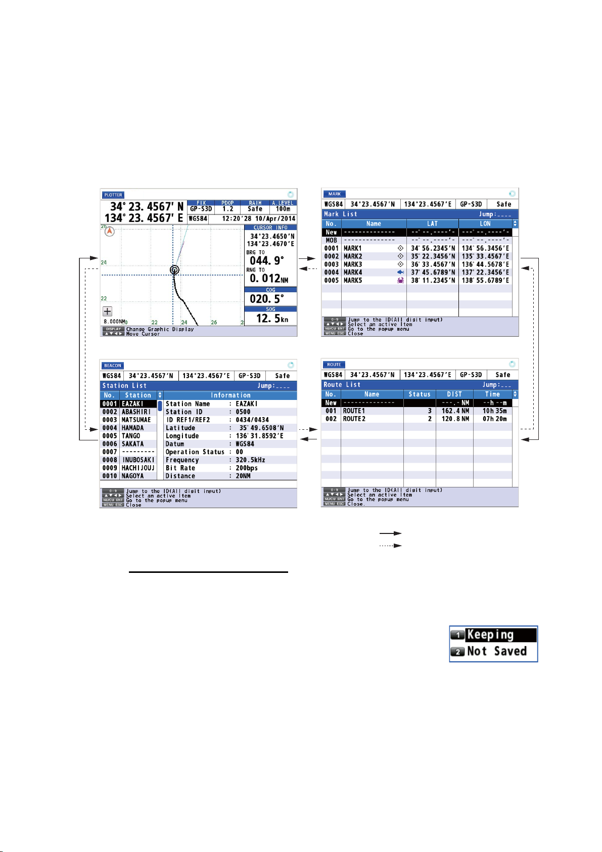
1.6 List Overview
The LIST key displays the mark list, route list and station list, in the sequence shown
below.
1. OPERATIONAL OVERVIEW
Any display
Station List
(Requires internal beacon receiver.)
How to save position in a list
1. Press the MENU/ESC key to open the main menu.
2. Select [8 System Setting] then [2 Plotter].
3. Select [7 List Number].
Mark List
Route List
: Short-press the LIST key
: Long-press the LIST key
4. Select [1 Keeping] or [2 Not Saved].
[Keeping]: Saves position in lists.
[Not Saved]: No. 0001 is always displayed at the top of the
list.
5. Press the MENU/ESC key to close the main menu.
1-9
Page 20
1. OPERATIONAL OVERVIEW
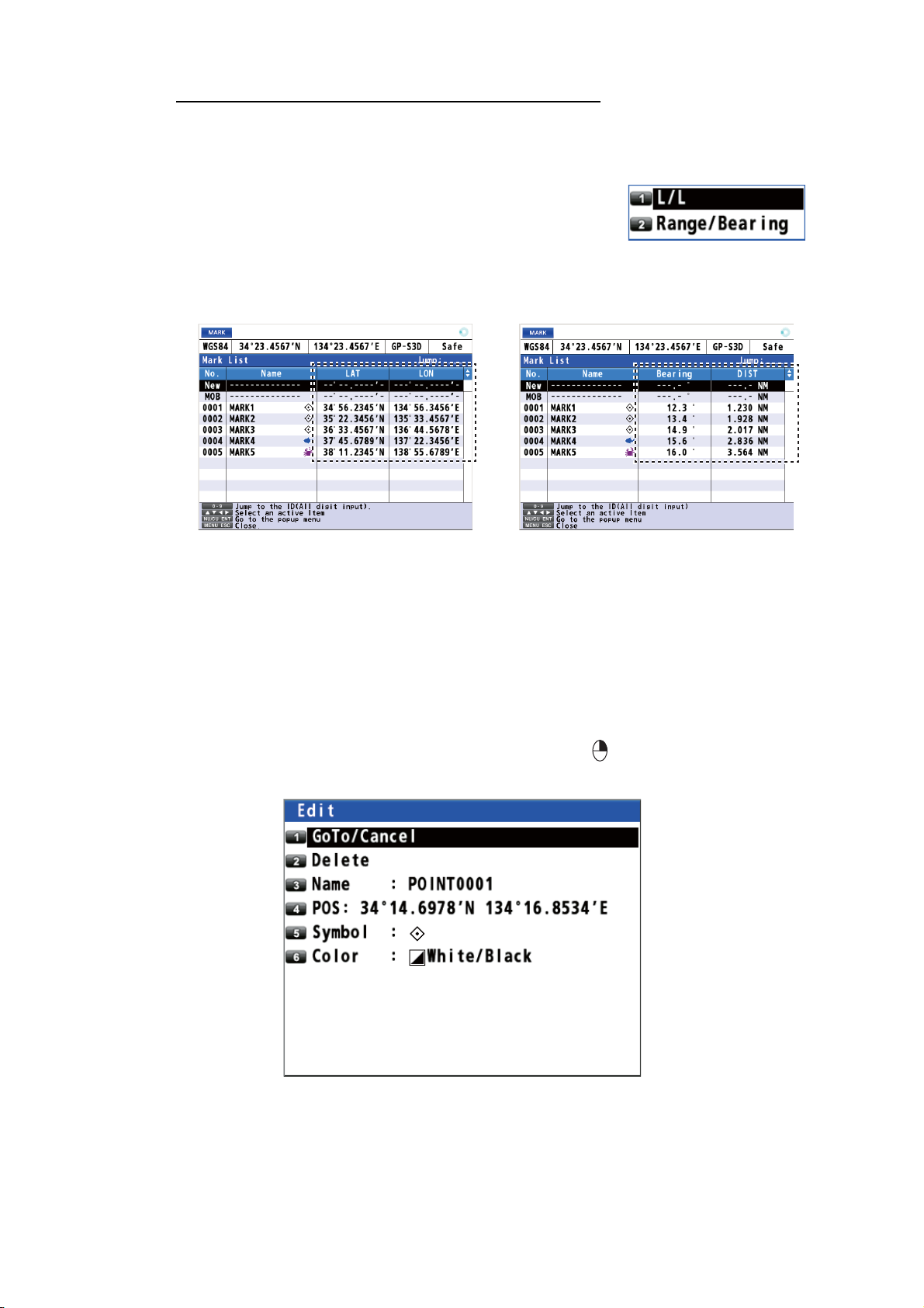
How to change the data to display on the mark list
1. Press the MENU/ESC key to open the main menu.
2. Select [8 System Setting] then [2 Plotter].
3. Select [8 List Information].
4. Select [1 L/L] or [2 Range/Bearing].
[L/L]: Displays latitude and longitude.
[Range/Bearing]: Displays the bearing and distance
from own ship to a mark or a waypoint.
5. Press the MENU/ESC key to close the main menu.
L/L
1.7 Context Menu Overview
You can display a context menu for track, mark, route, waypoint or MOB. For example,
do the following to open the context menu for a mark.
1. Press the CURSOR ON/OFF key to turn the cursor on.
2. Use the cursorpad to select a mark then press the key. The context menu
opens.
Range/Bearing
1-10
Page 21
2. PLOTTER DISPLAY OVERVIEW, TRACK
2.1 How to Set the Display
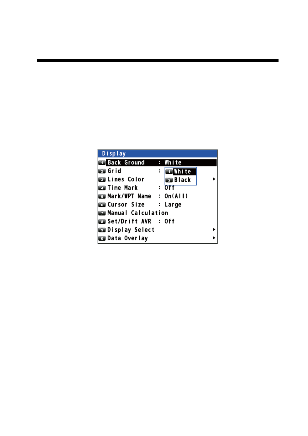
2.1.1 How to select the background color
You can select the background color to suit lighting conditions or environment (see
section 1.3).
1. Press the MENU/ESC key to open the main menu.
2. Select [1 Display] then [1 Back Ground].
3. Select [1 White] or [2 Black].
4. Press the MENU/ESC key to close the main menu.
2.1.2 How to zoom in or out the display
You can change the range scale on the plotter display. Press the ZOOM IN key to
zoom in the display and the ZOOM OUT key to zoom out the display. The horizontal
range is available among 0.125, 0.25, 0.5, 1, 2, 4, 8, 16, 32, 64, 128, 256, 512 and
1024 NM.
2.1.3 How to change the display orientation
The display orientation for the plotter display can be selected to north-up or courseup. Press the NU/CU ENT key to change the display orientation.
North-up
True north (0°) is at the top of the display. Own ship moves on the display in accordance with true motion. The land is stationary.
2-1
Page 22
2. PLOTTER DISPLAY OVERVIEW, TRACK
Course-up
When the destination is set, the destination is at the top of the display and the north
mark ( ) appears at the left side of the display.
When the destination is not set
ment you select the course-up and the north mark ( ) appears at the left side of the
display.
, own ship's course is upward on the display at the mo-
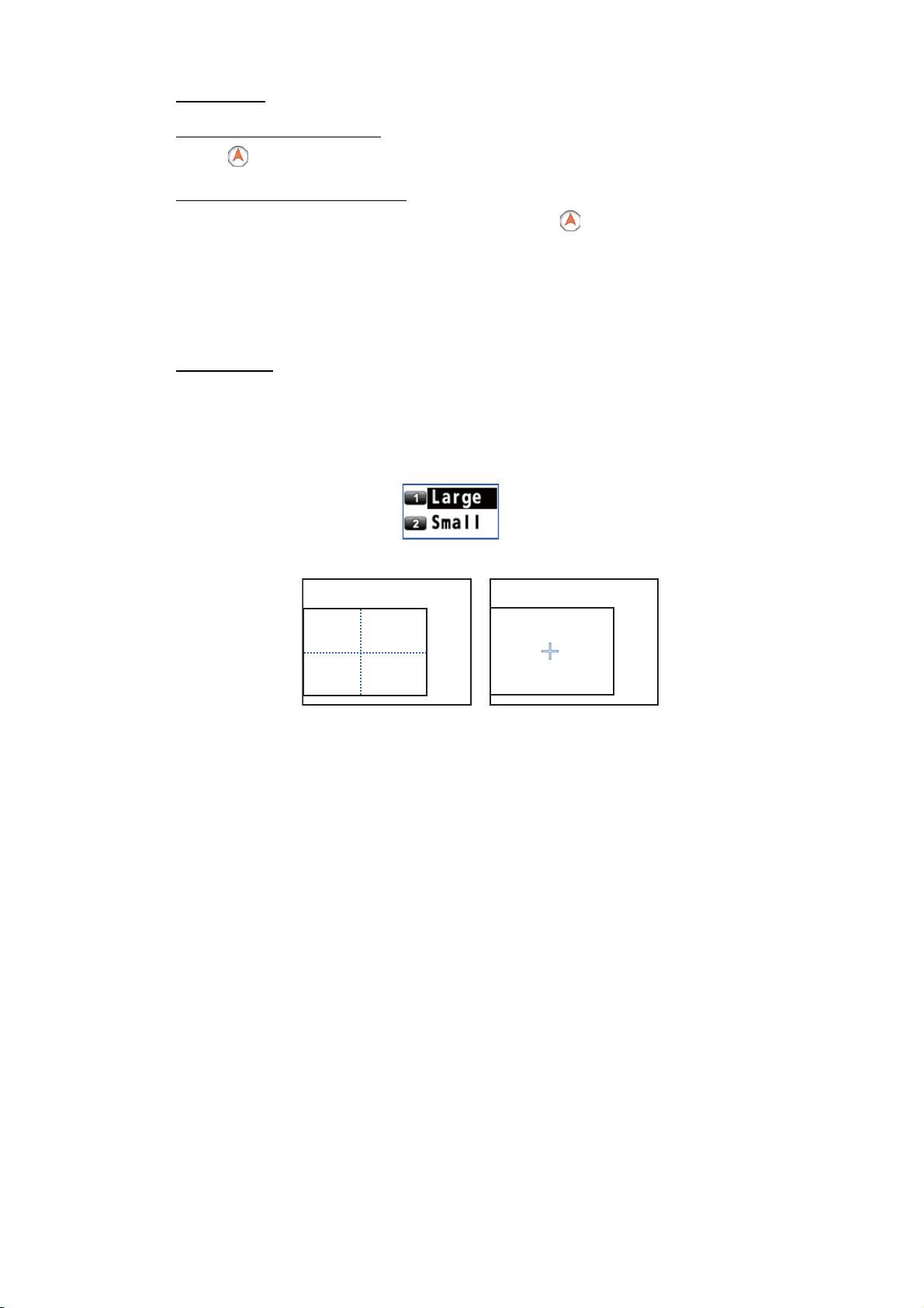
2.1.4 How to turn the cursor on/off, change cursor size
Press the CURSOR ON/OFF key to turn the cursor on or off.
Cursor size
You can change the cursor size.
1. Press the MENU/ESC key to open the main menu.
2. Select [1 Display] then [6 Cursor Size].
3. Select [1 Large] or [2 Small].
Large
4. Press the MENU/ESC key to close the main menu.
2.1.5 How to move the cursor
You can move the cursor with the cursorpad.
1. Press the CURSOR ON/OFF key to turn the cursor on.
2. Press or hold down the cursorpad. The cursor moves in the direction of the arrow
or diagonal. The display shifts when the cursor reaches an edge of the display, in
the direction opposite of the arrow pressed on the cursorpad. When the cursor is
turned on, the cursor position, the bearing and range from own ship to the cursor
appear at the right side of the display (see the plotter display on page 1-6).
2.1.6 How to shift the display
You can shift the display on the plotter display.
1. Press the CURSOR ON/OFF key to turn the cursor off.
2. Press or hold down the cursorpad.
Small
2-2
Page 23
2. PLOTTER DISPLAY OVERVIEW, TRACK
2.1.7 How to center the cursor position or ship's position
Cursor position
1. Press the CURSOR ON/OFF key to turn the cursor on.
2. Press the CENTER key.
Ship's position
1. Press the CURSOR ON/OFF key to turn the cursor off.
2. Press the CENTER key.
Note: When own ship reaches an edge of the display, own ship’s mark is automatically centered.
2.1.8 How to show or hide the grid and change its color
You can show or hide the grid and change its color (see "Plotter Display" on page 1-
6).
1. Press the MENU/ESC key to open the main menu.
2. Select [1 Display] then [2 Grid].
3. Select the grid color. To turn the grid off, select [8 Off]. When selecting [7 White/
Black], the grid color depends on the background color.
Background color Grid color
White Black
Black White
4. Press the MENU/ESC key to close the main menu.
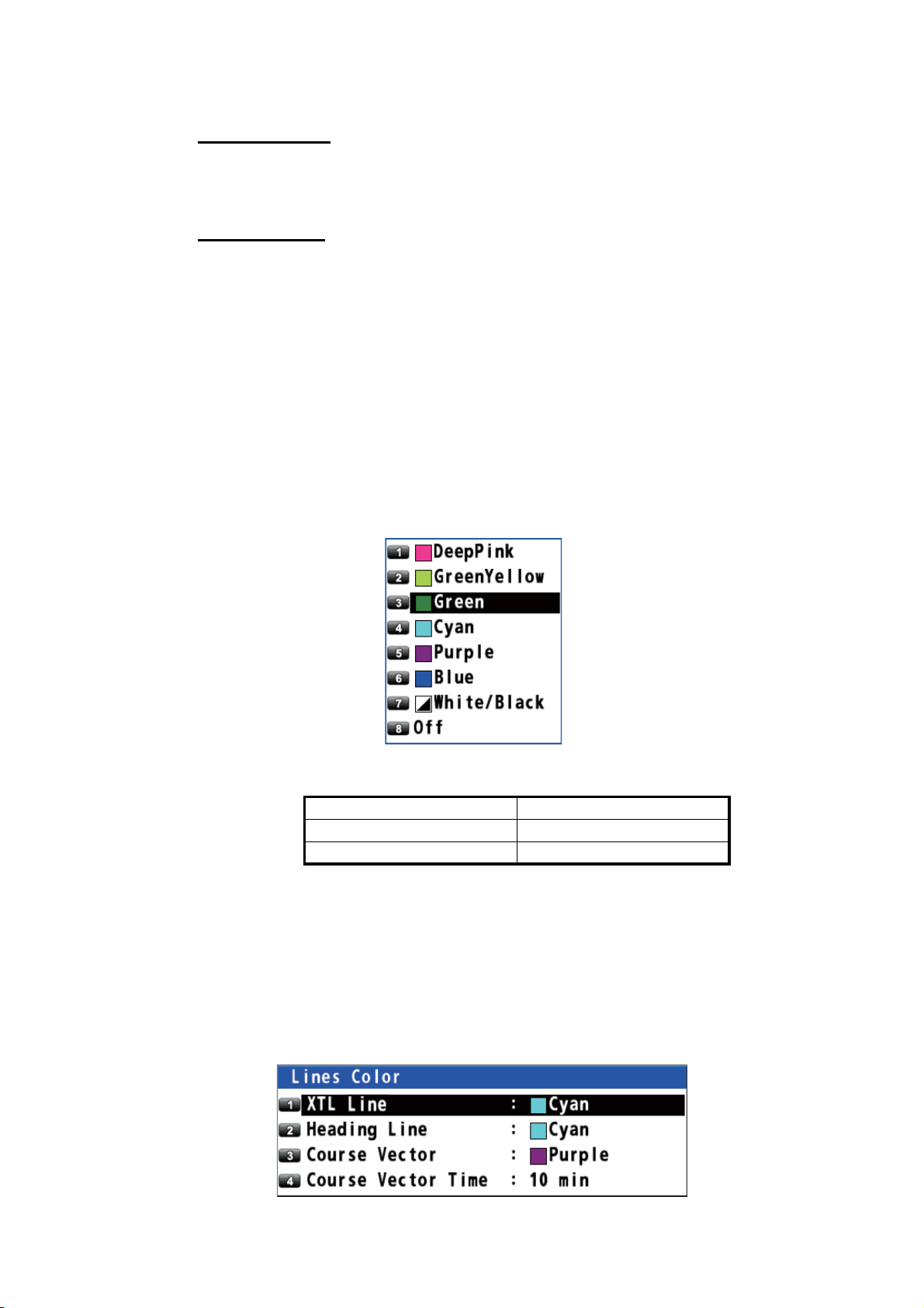
2.1.9 How to show or hide the XTL line and change its color
The XTL lines (see the illustration on page 5-1) straddle the intended course line and
they mark the XTL range. You can show or hide the lines and change their color.
1. Press the MENU/ESC key to open the main menu.
2. Select [1 Display] then [3 Lines Color].
2-3
Page 24
2. PLOTTER DISPLAY OVERVIEW, TRACK
3. Select [1 XTL Line].
4. Select the XTL line color. To turn the XTL line off, select [8 Off].
5. Press the MENU/ESC key to close the main menu.
2.1.10 How to show or hide the heading line and change its color
You can show or hide the heading line and change its color.
1. Press the MENU/ESC key to open the main menu.
2. Select [1 Display] then [3 Lines Color].
3. Select [2 Heading Line].
4. Select the heading line color. To turn the heading line off, select [8 Off].
5. Press the MENU/ESC key to close the main menu.
2.1.11 How to set the COG vector
The COG vector is a vector line that runs from own ship’s icon. This vector shows
speed and course of own ship. The top of a vector shows estimated position of own
ship after the selected vector time elapses.
Note: The COG vector is not displayed when there is no position data.
How to show or hide the COG vector and change its color
1. Press the MENU/ESC key to open the main menu.
2. Select [1 Display] then [3 Lines Color].
3. Select [3 Course Vector].
4. Select the COG vector color. To turn the COG vector off, select [8 Off].
5. Press the MENU/ESC key to close the main menu.
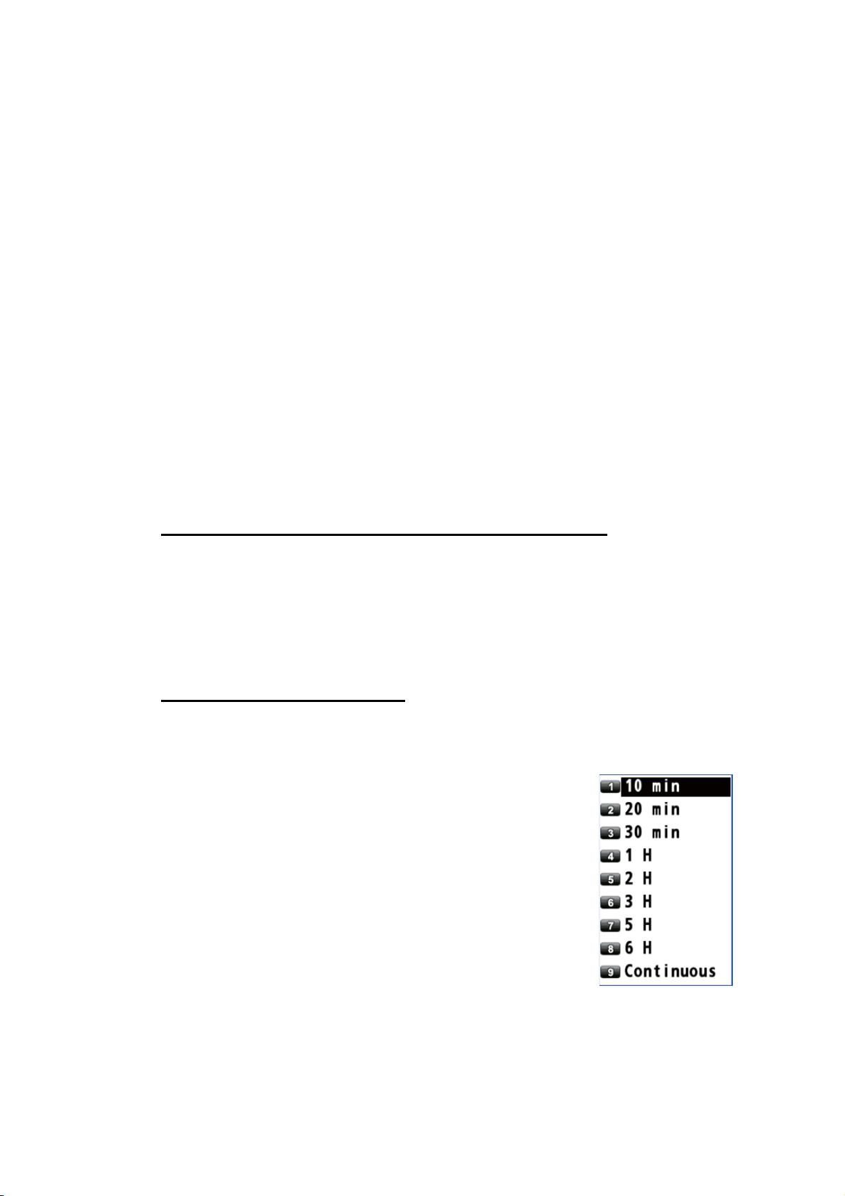
How to set the COG vector time
1. Press the MENU/ESC key to open the main menu.
2. Select [1 Display] then [3 Lines Color].
3. Select [4 Course Vector Time].
4. Select the time for the COG vector. If you select [9 Continuous], the COG vector extends to the edge of the display.
5. Press the MENU/ESC key to close the main menu.
2-4
Page 25
2. PLOTTER DISPLAY OVERVIEW, TRACK
2.1.12 How to display the time mark
You can display the time mark on the track every hour on the hour.
Track
T
T
T
T
1. Press the MENU/ESC key to open the main menu.
2. Select [1 Display] then [4 Time Mark].
3. Select the color for the time mark. To turn the time mark off, select [8 Off].
4. Press the MENU/ESC key to close the main menu.
2.1.13 How to display the names for marks and waypoints
You can display the names for marks and waypoints.
1. Press the MENU/ESC key to open the main menu.
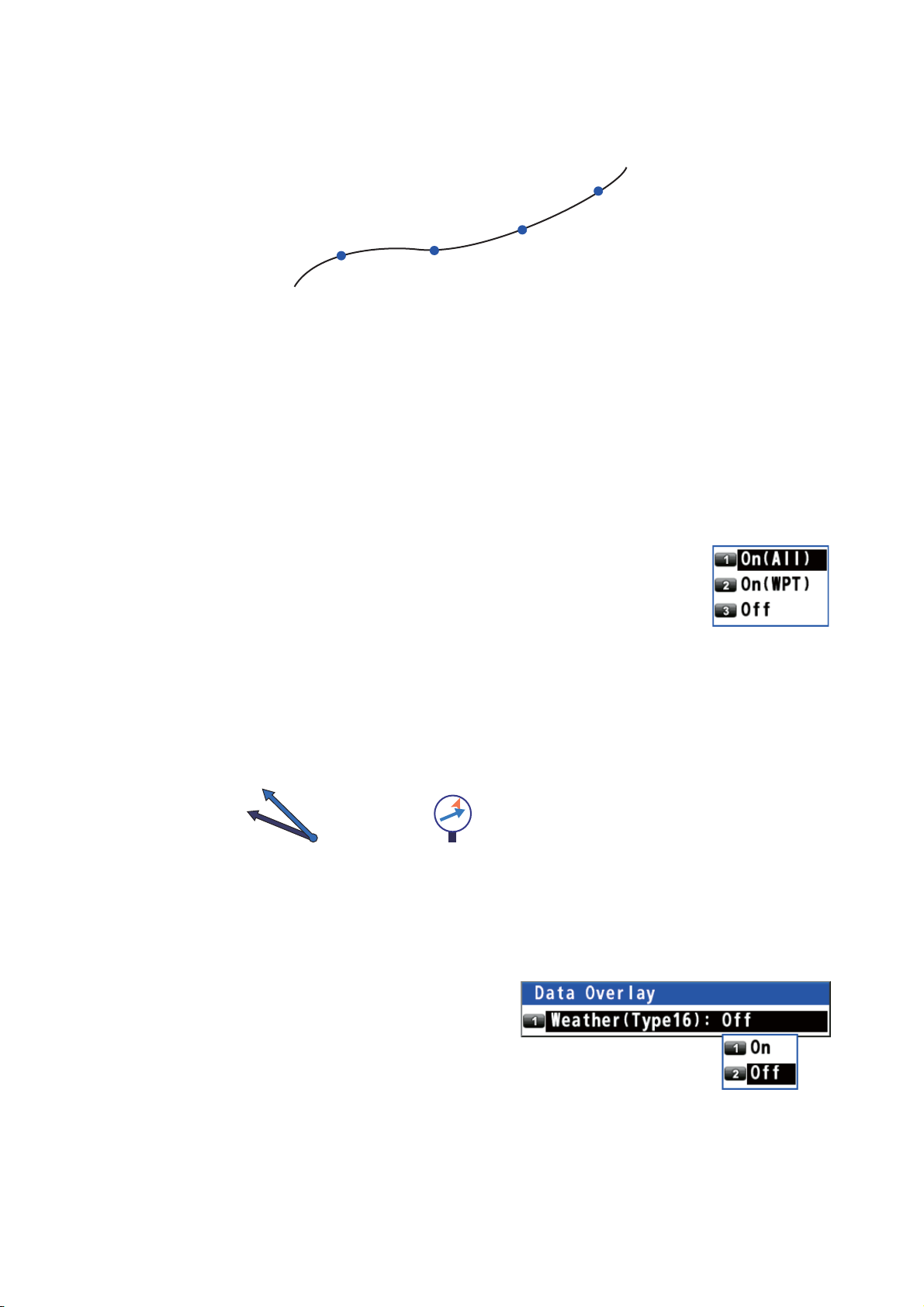
2. Select [1 Display] then [5 Mark/WPT Name].
3. Select [1 On (All)], [2 On (WPT)] or [3 Off].
[On (All)]: Displays the names for marks and waypoints.
[On (WPT)]: Displays the waypoint names.
[Off]: Turns off the names.
4. Press the MENU/ESC key to close the main menu.
2.1.14 How to show or hide the weather data
You can display the direction and the speed of the wind analyzed from type 16 message when the weather data is received from a beacon station (see page 7-2).
The arrow points in wind direction
akap
4m/s
Plotter display
akap
4m/s
Highway display
Note: This menu requires an internal or external beacon receiver.
1. Press the MENU/ESC key to open the main menu.
and its length changes according
to wind speed.
2. Select [1 Display] then [0 Data
Overlay].
3. Select [1 Weather (Type16)], then
[1 On] or [2 Off].
[On]: Displays the weather data
(type 16 message) on the plotter
display.
[Off]: Turns off the weather data (type 16 message) on the plotter display.
Note: On the highway display, the weather data is displayed regardless of on/off.
4. Press the MENU/ESC key to close the main menu.
2-5
Page 26
2. PLOTTER DISPLAY OVERVIEW, TRACK
2.2 Bearing Reference
Ship’s course and bearing to a waypoint are displayed in true or magnetic bearing.
Magnetic bearing is true bearing plus (or minus) earth’s magnetic variation.
2.2.1 How to select bearing reference
The default setting displays true bearing.
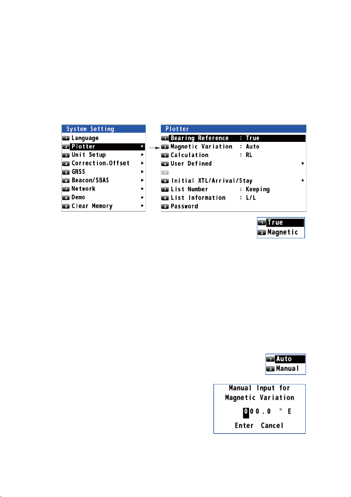
1. Press the MENU/ESC key to open the main menu.
2. Select [8 System Setting] then [2 Plotter].
3. Select [1 Bearing Reference].
4. Select [1 True] or [2 Magnetic].
[True]: Gyrocompass or satellite compass using true bearing
[Magnetic]: Magnetic compass
5. Press the MENU/ESC key to close the main menu.
When selecting [2 Magnetic] at step 4, follow the steps at paragraph 2.2.2.
2.2.2 How to set the magnetic variation
The location of the magnetic north pole is different from the geographical north pole.
This causes a difference between the true and magnetic north direction. This difference is called magnetic variation, and varies with respect to the observation point on
the earth. Magnetic variation is entered automatically or manually.
1. Press the MENU/ESC key to open the main menu.
2. Select [8 System Setting] then [2 Plotter].
3. Select [2 Magnetic Variation].
4. Select [1 Auto] or [2 Manual]. If you select [1 Auto], go to step 7.
For [2 Manual], go to step 5.
5. Enter the variation with the numeric keys. To
change the coordinate, select "E" then press
one of keys from 0 to 9.
2-6
6. Move the cursor to [Enter] then press the NU/
CU ENT key.
7. Press the MENU/ESC key to close the main
menu.
Page 27
2. PLOTTER DISPLAY OVERVIEW, TRACK
2.3 About Tracks
The GP-170 stores 1,000 points of track.
2.3.1 How to start or stop plotting and recording of the track
Press the PLOT ON/OFF key to start or stop plotting and recording of the track. The
pop-up message "Resuming Track Plot" or "Stopping Track Plot" appears at the left
side of the display for two seconds. When track plotting is stopped, the icon appears at the bottom left corner of the display.
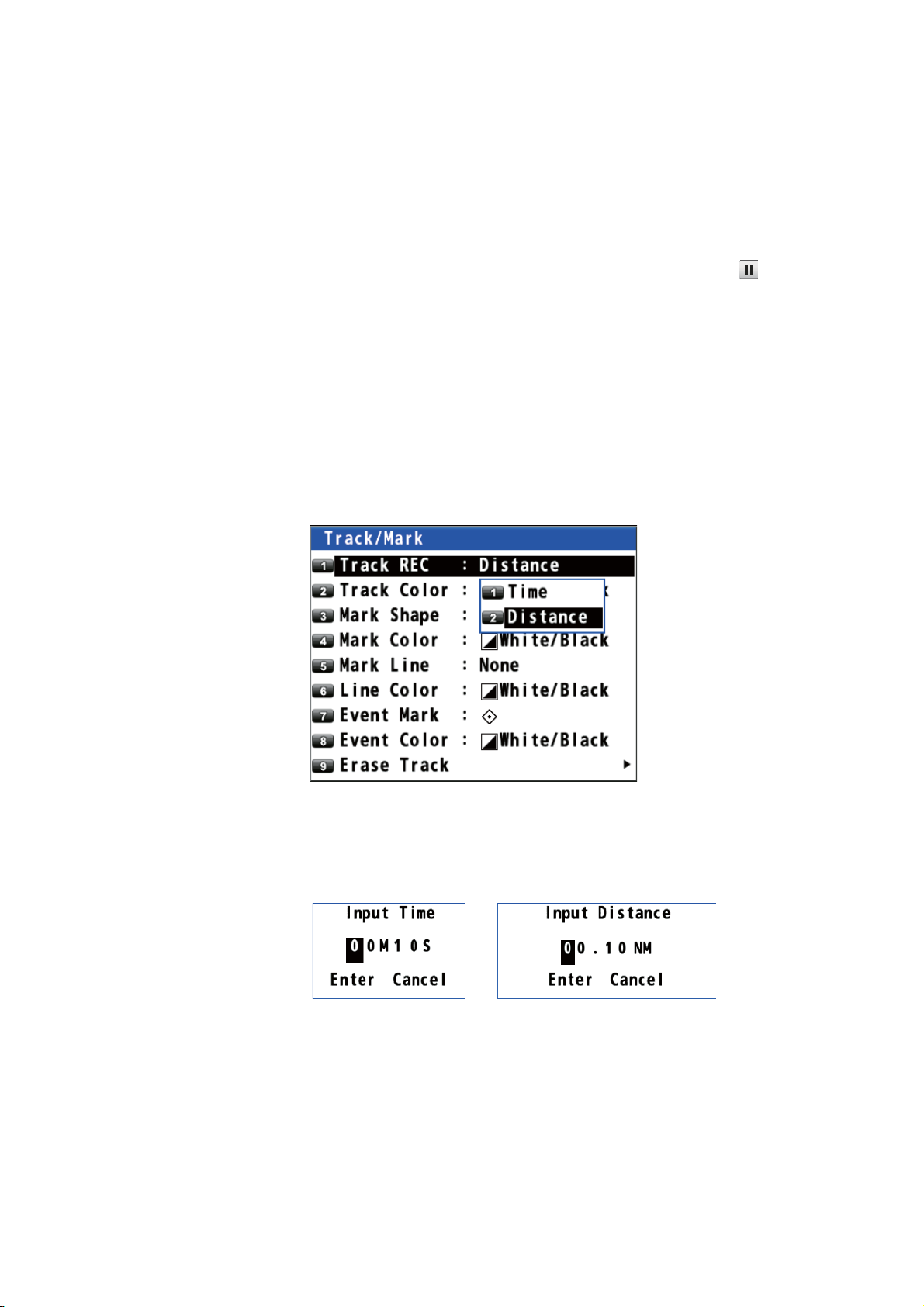
2.3.2 How to set the track plotting interval
In drawing the track, the position of your ship is stored into the memory of this equipment at an interval of time or distance. A shorter interval provides better reconstruction
of the track, but the storage time of the track is reduced. When the track memory becomes full, the oldest track is erased to make room for the latest.
1. Press the MENU/ESC key to open the main menu.
2. Select [2 Track/Mark] then [1 Track REC].
3. Select [1 Time] or [2 Distance].
[Time]: Enter the time interval with the numeric keys (setting range: 0001 (1 sec)
to 6000 (60 min)).
[Distance]: Enter the distance interval with the numeric keys (setting range: 00.01
to 99.99 NM).
Time Distance
4. Move the cursor to [Enter] then press the NU/CU ENT key.
5. Press the MENU/ESC key to close the main menu.
2-7
Page 28
2. PLOTTER DISPLAY OVERVIEW, TRACK
2.3.3 How to set the track color
You can select the track color as follows:
1. Press the MENU/ESC key to open the main menu.
2. Select [2 Track/Mark] then [2 Track Color].
3. Select the track color.
4. Press the MENU/ESC key to close the main menu.
How to change the color of selected track
1. Put the cursor on the track.
2. Press the key to open the context menu.
3. Select [1 Change Color].
4. Select the color to change.
5. Press the MENU/ESC key to close the context menu.
2.3.4 How to erase the track
How to erase all tracks from the main menu
1. Press the MENU/ESC key to open the main menu.
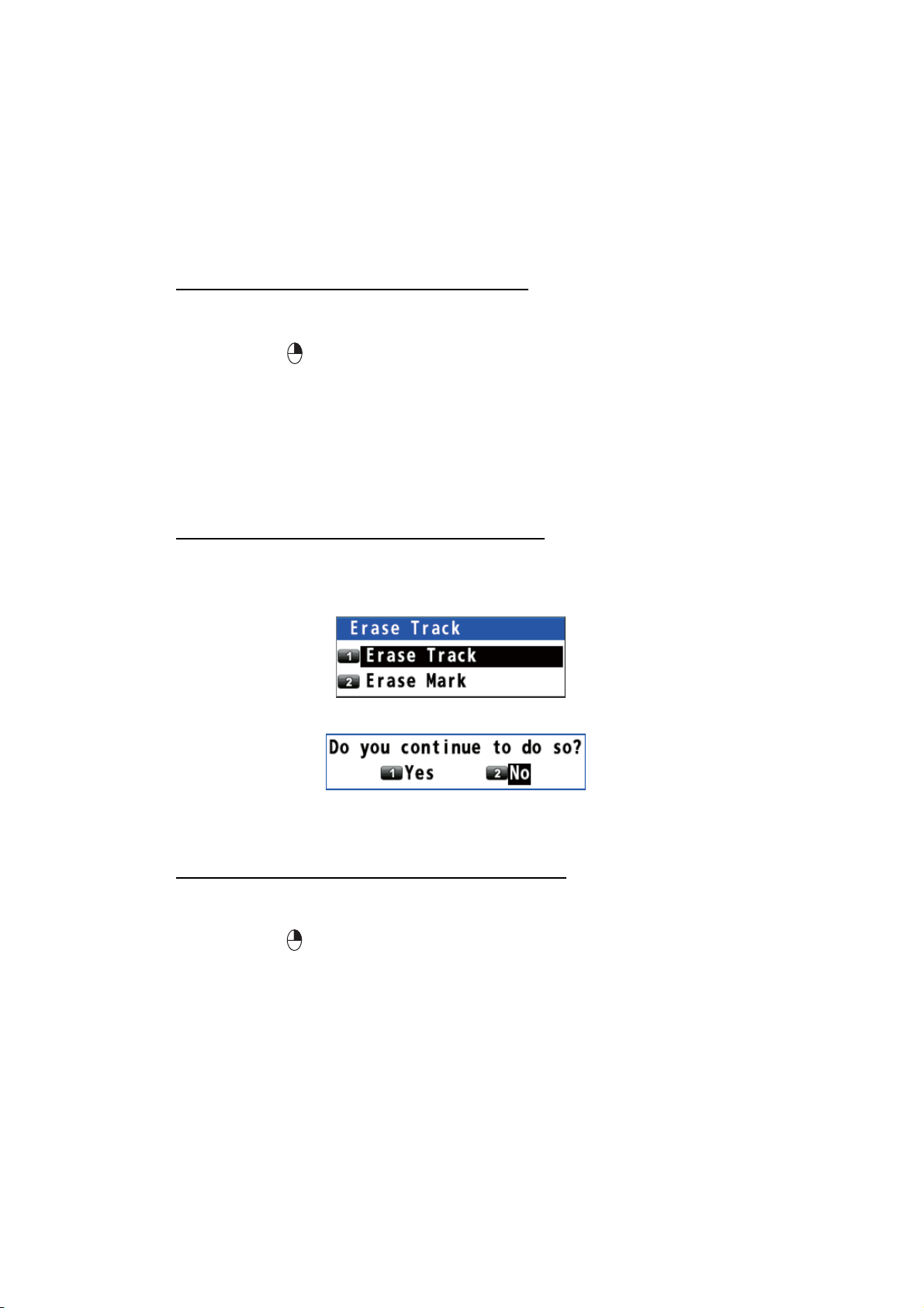
2. Select [2 Track/Mark] then [9 Erase Track].
3. Select [1 Erase Track]. The confirmation message appears.
4. Select [1 Yes].
5. Press the MENU/ESC key to close the main menu.
How to erase all tracks from the context menu
1. Put the cursor on a track.
2. Press the key to open the context menu.
3. Select [2 Erase All]. The confirmation message appears.
2-8
4. Select [1 Yes].
Page 29
3. MARKS
You can put marks on the plotter display to indicate good fishing spot, location of traps,
etc. Marks have 16 shapes and seven colors. Also, marks can be connected with
lines.
3.1 How to Enter a Mark on the Plotter Display
3.1.1 How to preset mark appearance
Set the default mark shape, color, line type to use when entering a mark.
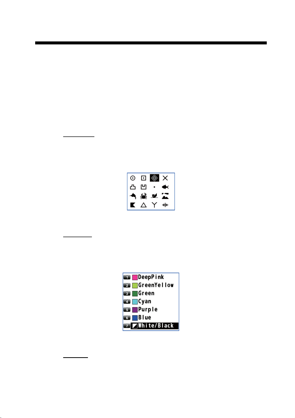
Mark shape
You can select a mark shape from 16 types.
1. Press the MENU/ESC key to open the main menu.
2. Select [2 Track/Mark] then [3 Mark Shape].
3. Use the cursorpad to select the shape then press the NU/CU ENT key.
4. Press the MENU/ESC key to close the main menu.
Mark color
You can select a mark color from seven colors.
1. Press the MENU/ESC key to open the main menu.
2. Select [2 Track/Mark] then [4 Mark Color].
3. Select the color.
4. Press the MENU/ESC key to close the main menu.
Mark line
Marks can be connected with lines, and three types of lines are available.
1. Press the MENU/ESC key to open the main menu.
3-1
Page 30

3. MARKS
2. Select [2 Track/Mark] then [5 Mark Line].
3. Select the line type.
• [None]: None • [Solid]:
• [Dash]: • [Alternate Dash]:
4. Press the MENU/ESC key to close the main menu.
When continuously entering marks by the method described in paragraph 3.1.2, the
marks are connected with the selected line.
Mark line color
You can select a mark line color from seven colors.
1. Press the MENU/ESC key to open the main menu.
2. Select [2 Track/Mark] then [6 Line Color].
3. Select the color.
4. Press the MENU/ESC key to close the main menu.
3.1.2 How to enter a mark at the cursor position
1. Press the CURSOR ON/OFF key to turn the cursor on.
2. Use the cursorpad to place the cursor on the location for a mark.
3. Press the MARK EVENT key to put the mark. This mark is named with the youngest unused mark number (for example, "POINT0001"), and saved to the mark list.
3.1.3 How to enter a mark from the mark list
At the cursor position
1. Press the MENU/ESC key to open the main menu.
2. Select [3 Navigation] then [1 Mark Registration].
3-2
Page 31

3. With the cursor on the [New] line, press the NU/CU ENT key.
4. Select [1 Cursor].
5. Use the cursorpad to select the position for the mark.
6. Press the NU/CU ENT key.
3. MARKS
7. Change the name (see page 4-6), position, symbol or color if necessary.
8. Select [9 Register]. The confirmation message appears.
9. Select [1 Yes] or [2 No].
[Yes]: Marks are registered with connection lines.
[No]: Marks are registered without connection lines.
10. Press the MENU/ESC key to close the main menu.
By entering L/L
1. Press the MENU/ESC key to open the main menu.
2. Select [3 Navigation] then [1 Mark Registration].
3. With the cursor on the [New] line, press the NU/CU ENT key.
3-3
Page 32

3. MARKS
4. Select [2 Input L/L].
5. Enter latitude and longitude with the numeric keys. (To change the coordinate, select "N" or "E" then press one of keys from 0 to 9.)
6. Move the cursor to [Enter] then press the NU/CU ENT key.
7. Change the name (see page 4-6), position, symbol or color if necessary.
8. Select [9 Register]. The confirmation message appears.
9. Select [1 Yes] or [2 No].
[Yes]: Marks are registered with connection lines.
[No]: Marks are registered without connection lines.
10. Press the MENU/ESC key to close the main menu.
3-4
Page 33

3.2 How to Enter an Event Mark
Event marks can be used to mark an important present position on the plotter display.
3.2.1 How to preset event mark appearance
Set the default event mark shape and color to use when entering an event mark.
Event mark shape
You can select an event mark shape from 16 types.
1. Press the MENU/ESC key to open the main menu.
2. Select [2 Track/Mark] then [7 Event Mark].
3. MARKS
3. Use the cursorpad to select the shape then press the NU/CU ENT key.
4. Press the MENU/ESC key to close the main menu.
Event mark color
You can select an event mark color from seven colors.
1. Press the MENU/ESC key to open the main menu.
2. Select [2 Track/Mark] then [8 Event Color].
3. Select the color.
4. Press the MENU/ESC key to close the main menu.
3.2.2 How to enter an event mark at own ship’s position
1. Press the CURSOR ON/OFF key to turn the cursor off.
2. Press the MARK EVENT key on the plotter display. This mark is named with the
youngest unused mark number (for example, "POINT0001"), and saved to the
mark list.
3.2.3 How to enter an event mark from the mark list
1. Press the MENU/ESC key to open the main menu.
2. Select [3 Navigation] then [1 Mark Registration].
3. With the cursor on the [New] line, press the NU/CU ENT key.
3-5
Page 34

3. MARKS
4. Select [3 OwnShip Position].
5. Change the name (see page 4-6), position, symbol or color if necessary.
6. Select [9 Register]. The confirmation message appears.
7. Select [1 Yes] or [2 No].
[Yes]: Marks are registered with connecting lines.
[No]: Marks are registered without connecting lines.
8. Press the MENU/ESC key to close the main menu.
3.3 How to Enter a MOB Mark on the Plotter Display
The MOB mark denotes man overboard position. You can use it as an aid to rescue.
Press the MOB key to put a MOB mark. When the key is pressed, own ship's position
is registered as a MOB mark ( ). The following message appears.
Select [1 Yes]. The position for the MOB mark becomes the destination. A line is
drawn between own ship and the MOB mark. This line shows the shortest course to
go to the MOB position. The bearing and range from own ship to the MOB position are
displayed at the right of the display. Only one MOB mark can be put on the plotter display, and each time the MOB key is operated the previous MOB mark and its position
data are written over.
3-6
Page 35

3.4 How to Edit a Mark or an Event Mark
You can edit name, position, shape and color for a mark or an event mark on the plotter display or through the mark list.
On the plotter display
1. Press the CURSOR ON/OFF key to turn the cursor on.
2. Use the cursorpad to select the (event) mark to edit then press the key to open
the context menu.
3. MARKS
3. Select appropriate options to edit then set them.
4. Press the MENU/ESC key to close the context menu.
From the mark list
1. Press the MENU/ESC key to open the main menu.
2. Select [3 Navigation] then [1 Mark Registration].
3. Use the cursorpad (S or T) to select the (event) mark to edit then press the NU/
CU ENT key. The [Edit] window same as above appears.
Note: You can select the (event) mark to edit by entering its mark no. with the nu-
meric keys.
Enter the mark no. (e.g. “0001”)
with the numeric key then press
the NU/CU ENT key.
4. Select appropriate options to edit then set them.
5. Press the MENU/ESC key to close the main menu.
3-7
Page 36

3. MARKS
3.5 How to Erase Marks
You can erase a mark(s), an event mark(s) or a MOB mark.
Note: You cannot erase the mark used as the current destination except the MOB
mark.
How to erase a mark from the context menu
1. Press the CURSOR ON/OFF key to turn the cursor on.
2. Use the cursorpad to select the mark to erase then press the key to open the
context menu.
3. Select [2 Delete].
How to erase a mark with the ACK/DELETE key
1. Press the CURSOR ON/OFF key to turn the cursor on.
2. Use the cursorpad to select the mark to erase
then press the ACK/DELETE key. The confirmation message appears.
3. Select [1 Yes].
For (event) mark For MOB mark
How to erase a mark from the mark list
Note: This menu is not available for a MOB mark.
1. Press the MENU/ESC key to open the main menu.
2. Select [3 Navigation] then [1 Mark Registration].
3. Use the cursorpad (S or T) to select the mark to erase then press the NU/CU
ENT key.
4. Select [2 Delete].
5. Press the MENU/ESC key to close the main menu.
How to erase all marks
Note: This menu is not available for a MOB mark.
1. Press the MENU/ESC key to open the main menu.
2. Select [2 Track/Mark] then [9 Erase Track].
3-8
3. Select [2 Erase Mark]. The confirmation message appears.
4. Select [1 Yes].
5. Press the MENU/ESC key to close the main menu.
Page 37

4. ROUTES
To navigate from one place to another, several course changes are required. The
point for course change is called a waypoint. The sequence of waypoints (marks for
course changes) leading to the last destination is called a route.
4.1 How to Create a Route
A maximum of 99 routes can be created and a route can have a maximum of 1,000
waypoints.
4.1.1 How to preset the settings for routes
XTL (Cross-track limit) range
The XTL range is the maximum distance your boat is allowed to go off course before
the XTE notice (see section 6.3) is given.
1. Press the MENU/ESC key to open the main menu.
2. Select [8 System Setting] then [2 Plotter].
3. Select [6 Initial XTL/Arrival/Stay].
4. Select [1 XTL].
5. Enter the XTL distance with the numeric keys
(setting range: 0.001 to 9.999 NM).
6. Move the cursor to [Enter] then press the NU/
CU ENT key.
7. Press the MENU/ESC key to close the main menu.
4-1
Page 38

4. ROUTES
Arrival radius
You can receive an audiovisual notice when you are within the specified distance from
a waypoint (see section 6.2).
1. Press the MENU/ESC key to open the main menu.
2. Select [8 System Setting] then [2 Plotter].
3. Select [6 Initial XTL/Arrival/Stay].
4. Select [2 Arrival Radius].
5. Enter the arrival radius with the numeric keys (setting range: 0.001 to 9.999 NM).
6. Move the cursor to [Enter] then press the NU/CU ENT key.
7. Press the MENU/ESC key to close the main menu.
Staying time
You can set the time the GP-170 waits at a waypoint in a followed route before it
switches to the next waypoint. See the note in "Departure time" on this page.
1. Press the MENU/ESC key to open the main menu.
2. Select [8 System Setting] then [2 Plotter].
3. Select [6 Initial XTL/Arrival/Stay].
4. Select [3 Stay Time].
5. Enter the staying time at the waypoint with the numeric
keys.
6. Move the cursor to [Enter] then press the NU/CU ENT
key.
7. Press the MENU/ESC key to close the main menu.
SOG
Set the speed to use to follow a route.
1. Press the MENU/ESC key to open the main menu.
2. Select [8 System Setting] then [2 Plotter].
3. Select [6 Initial XTL/Arrival/Stay].
4. Select [4 SOG].
5. Enter the speed with the numeric keys.
6. Move the cursor to [Enter] then press the NU/
CU ENT key.
4-2
7. Press the MENU/ESC key to close the main
menu.
Departure time
You can set the date and time to depart from the waypoint on the route.
Note: When the departure date and time set is before the current date and time, the
staying time has priority. When the departure date and time set is after the current date
and time, the departure time has priority.
1. Press the MENU/ESC key to open the main menu.
Page 39

4. ROUTES
2. Select [8 System Setting] then [2 Plotter].
3. Select [6 Initial XTL/Arrival/Stay].
4. Select [5 Departure Time].
5. Enter the date and time departing
from the starting point with the numeric keys.
6. Move the cursor to [Enter] then
press the NU/CU ENT key.
7. Press the MENU/ESC key to
close the main menu.
2000 / 01 / 01 00 : 00
Month
Day
Minute
Hour
Year
Range and bearing calculation method
When you set a destination, the equipment displays the range, bearing and course to
the destination. Range and bearing are calculated by the Rhumb Line or Great Circle
method.
1. Press the MENU/ESC key to open the main menu.
2. Select [8 System Setting] then [2 Plotter].
3. Select [3 Calculation].
4. Select [1 RL] or [2 GC].
[RL] (Rhumb Line): This method calculates the range and bearing between two points drawn on a nautical chart. Since the bearing is kept
constant it is ideal for short-range navigation.
[GC] (Great Circle): This course line is the shortest course between two points on
the surface of the earth, like stretching a piece of string between two points on
earth. Frequent bearing changes are required to navigate by this method. For
long-range navigation, divide the Great Circle route into several routes, and navigate each route by Rhumb Line.
5. Press the MENU/ESC key to close the main menu.
Route color
You can select the route color from seven colors.
1. Press the MENU/ESC key to open the main menu.
2. Select [8 System Setting] then [2 Plotter].
3. Select [6 Initial XTL/Arrival/Stay].
4. Select [6 Route Color].
5. Select a color for route lines and waypoints.
6. Press the MENU/ESC key to close the main menu.
4.1.2 How to create a new route with the cursor and the ROUTE key
1. Press the CURSOR ON/OFF key to turn the cursor on.
2. Long-press the ROUTE key. The message "Route Setting" appears on the display.
3. Use the cursorpad to place the cursor on the location for the first waypoint then
press the NU/CU ENT key.
4-3
Page 40

4. ROUTES
4. Use the cursorpad to place the cursor on the location for the next waypoint then
press the NU/CU ENT key. Repeat this step to enter all waypoints.
5. At the last waypoint, press the ROUTE key to complete the route.
4.1.3 How to create a new route from the route list
With the cursorpad
1. Press the MENU/ESC key to open the main menu.
2. Select [3 Navigation] then [2 Route Registration].
3. With the cursor on the [New] line, press the NU/CU ENT key.
4. Select [1 Cursor].
5. Use the cursorpad to select the position for the first waypoint.
6. Press the NU/CU ENT key.
4-4
The values set in paragraph 4.1.1 are displayed at the menu items [3 XTL] to [7
DEP TIME]. You can change these values for each waypoint if required.
Page 41

4. ROUTES
7. Select [9 Add] to enter the waypoint.
8. Repeat steps 4 to 7 to enter all waypoints.
9. Press the MENU/ESC key to complete the route and close the main menu.
By entering L/L
1. Press the MENU/ESC key to open the main menu.
2. Select [3 Navigation] then [2 Route Registration].
3. With the cursor on the [New] line, press the NU/CU ENT key.
4. Select [2 Input L/L].
5. Enter latitude and longitude for the first
waypoint with the numeric keys. (To
change the coordinate, select "N" or
"E" then press one of keys from 0 to 9.)
6. Move the cursor to [Enter] then press
the NU/CU ENT key.
7. If necessary, change the settings of the route.
8. Select [9 Add] to enter the waypoint.
9. Repeat steps 4 to 8 to enter all waypoints.
10. Press the MENU/ESC key to complete the route and close the main menu.
From the mark list
1. Press the MENU/ESC key to open the main menu.
2. Select [3 Navigation] then [2 Route Registration].
3. With the cursor on the [New] line, press the NU/CU ENT key.
4. Select [3 From Mark List] to show the mark list.
5. Use the cursorpad (S or T) to select the mark to use for the route.
6. Press the NU/CU ENT key.
7. If necessary, change the settings of the route.
8. Select [9 Add] to enter the waypoint.
9. Repeat steps 4 to 8 to enter all waypoints.
10. Press the MENU/ESC key to complete the route and close the main menu.
4-5
Page 42
4. ROUTES
4.2 How to Edit a Route
You can edit a route from the plotter display or through the route list.
4.2.1 How to change the route name or color
From the route list
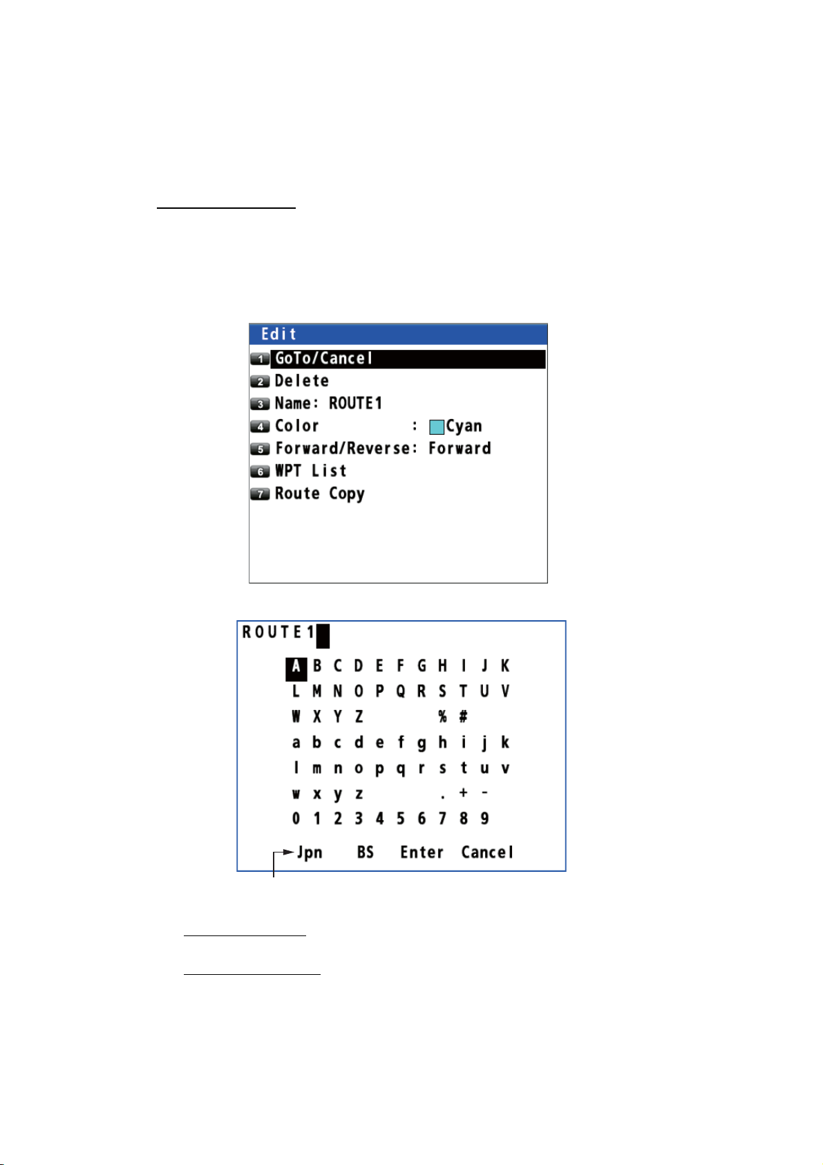
1. Press the MENU/ESC key to open the main menu.
2. Select [3 Navigation] then [2 Route Registration] to display the route list.
3. Use the cursorpad (S or T) or enter the route no. at the “Jump” position to select
the route to edit then press the NU/CU ENT key.
4. To change the name, select [3 Name].
To change input mode from English to Japanese,
select [Jpn] then press the NU/CU ENT key.
5. To add characters
NU/CU ENT key.
To delete characters
key.
, use the cursorpad to select a character to add then press the
, use the cursorpad to select [BS] then press the NU/CU ENT
4-6
6. Use the cursorpad to select [Enter] then press the NU/CU ENT key.
7. To change the color, select [4 Color], then select the new color.
8. Press the MENU/ESC key to close the main menu.
Page 43

On the plotter display
1. Press the CURSOR ON/OFF key to turn the cursor on.
2. Put the cursor on any route line of the route to edit then press the key. The
context menu opens.
3. Do steps 4 to 7 in "From the route list" on page 4-6 as appropriate.
4. Press the MENU/ESC key to close the context menu.
4.2.2 How to edit a waypoint in a route
1. Press the CURSOR ON/OFF key to turn the cursor on.
2. Use the cursorpad to select the waypoint in the route to edit then press the key
to open the context menu.
4. ROUTES
3. To change the name, select [1 Name].
4. To add characters
NU/CU ENT key.
To delete characters
key.
5. Use the cursorpad to select [Enter] then press the NU/CU ENT key.
6. To change the position, select [2 POS], then enter latitude and longitude for the
waypoint with the numeric keys. (To change the coordinate, select "N" or "E" then
press one of keys from 0 to 9.)
7. Use the cursorpad to select [Enter] then press the NU/CU ENT key.
8. To change the XTL range scale, select [3 XTL],
then enter the XTL range scale with the numeric keys.
9. Use the cursorpad to select [Enter] then press
the NU/CU ENT key.
10. To change the arrival radius, select [4 ARV],
then enter the arrival radius with the numeric keys.
11. Use the cursorpad to select [Enter] then press the NU/CU ENT key.
, use the cursorpad to select a character to add then press the
, use the cursorpad to select [BS] then press the NU/CU ENT
4-7
Page 44

4. ROUTES
12. To change the staying time, select [5 STAY], then enter
the staying time at the waypoint with the numeric keys.
13. Use the cursorpad to select [Enter] then press the NU/
CU ENT key.
14. To change the SOG, select [6 SOG], then enter the speed with the numeric keys.
15. Use the cursorpad to select [Enter] then
press the NU/CU ENT key.
16. To change the departure time, select [7 DEP
TIME], then enter the date and time departing from the waypoint with the numeric
keys
17. Use the cursorpad to select [Enter] then press the NU/CU ENT key.
18. Press the MENU/ESC key to close the context menu.
4.2.3 How to temporarily deselect a waypoint in a route
You can temporarily deselect an unnecessary waypoint from a route. Using the route
created in the illustration shown below as an example, deselect "POINT0003".
POINT0003
POINT0002
POINT0001
POINT0004
If you reconstruct the route without "POINT0003" it would look like the illustration below.
Skipped point
POINT0002
POINT0001
POINT0004
POINT0005
POINT0005
4-8
1. Press the CURSOR ON/OFF key to turn the cursor on.
2. Use the cursorpad to select the waypoint in the route to skip then press the
key. The context menu opens.
3. Select [8 Skip].
4. Select [2 On].
5. Press the MENU/ESC key to close the context menu.
Page 45

4. ROUTES
How to restore the skipped waypoint
To restore the skipped waypoint if you have not passed it, do the following:
1. Press the CURSOR ON/OFF key to turn the cursor on.
2. Put the cursor on any route line of the route which contains the skipped waypoint
then press the key to open the context menu.
3. Select [6 WPT List]. The ( ) icon is displayed on the skipped waypoint.
Skipped
waypoint
4. Use the cursorpad (S or T) to select the skipped waypoint then press the NU/CU
ENT key.
5. Select [8 Skip].
6. Select [1 Off].
7. Press the MENU/ESC key to close the context menu.
4.2.4 How to delete a waypoint from a route
How to erase a waypoint from the context menu
1. Press the CURSOR ON/OFF key to turn the cursor on.
2. Use the cursorpad to select the waypoint to delete then press the key to open
the context menu.
3. Select [0 Delete].
4-9
Page 46

4. ROUTES
How to erase a waypoint with the ACK/DELETE key
1. Press the CURSOR ON/OFF key to turn the cursor on.
2. Use the cursorpad to select the waypoint to delete then
press the ACK/DELETE key. The confirmation message
appears.
3. Select [1 Yes].
How to erase a waypoint from the route list
1. Press the MENU/ESC key to open the main menu.
2. Select [3 Navigation] then [2 Route Registration].
3. Use the cursorpad (S or T) to select the route no. which contains the waypoint
to delete then press the NU/CU ENT key.
4. Select [6 WPT List].
5. Use the cursorpad (S or T) to select the waypoint to delete then press the NU/
CU ENT key.
6. Select [0 Delete].
7. Press the MENU/ESC key to close the main menu.
4.2.5 How to insert a waypoint in a route
You can insert a waypoint backward or forward of the selected waypoint in a route. For
example, to insert a waypoint backward or forward of "POINT0003", do the following:
POINT0002
POINT0001
1. Press the CURSOR ON/OFF key to turn the cursor on.
2. Use the cursorpad to select the waypoint (in this example, "POINT0003") then
press the key to open the context menu.
3. Select [9 Insert].
POINT0003
POINT0004
POINT0005
4-10
4. Select [1 Forward] or [2 Back].
[Forward]: Insert a waypoint forward of the selected waypoint.
[Back]: Insert a waypoint backward of the selected waypoint.
“Back” when
selecting [2 Back].
5. Select [1 Cursor], [2 Input L/L] or [3 From Mark List].
6. Set a waypoint position refer to paragraph 4.1.3. The context menu closes after
selecting [9 Add].
Page 47

4.2.6 How to change the route direction
You can change the direction to travel a route.
1. Press the MENU/ESC key to open the main menu.
2. Select [3 Navigation] then [2 Route Registration] to show the route list.
3. Use the cursorpad (S or T) to select the route to change its direction then press
the NU/CU ENT key to display the [Edit] window. This window can be opened as
the context menu (see "On the plotter display" in paragraph 4.2.1).
4. Select [5 Forward/Reverse].
5. Select [1 Forward] or [2 Reverse].
[Forward]: Follow the waypoints in the order they were entered.
[Reverse]: Follow the waypoints in reverse order. The arrows on the route point in
the direction to follow the route (see the illustration on page 5-1).
6. Press the MENU/ESC key to close the main menu.
The ( ) icon is displayed on the route for which [Reverse] is selected.
4. ROUTES
[Reverse]
is selected.
4.2.7 How to copy the route
The copy feature lets you save a registered route under a new route number. This is
useful for creating a new route with parts of a previously registered route.
1. Press the MENU/ESC key to open the main menu.
2. Select [3 Navigation] then [2 Route Registration] to show the route list.
3. Use the cursorpad (S or T) to select the route to copy then press the NU/CU ENT
key to display the [Edit] window. This window can be opened as the context menu
(see "On the plotter display" in paragraph 4.2.1).
4-11
Page 48

4. ROUTES
4. Select [7 Route Copy]. "ROUTE1" is copied in the illustration below.
[ROUTE1] is
copied here.
5. Edit the route as appropriate (see section 4.2).
6. Press the MENU/ESC key to close the main menu.
4.3 How to Erase a Route
How to erase a route from the context menu
1. Press the CURSOR ON/OFF key to turn the cursor on.
2. Put the cursor on any route line of the route to delete then press the key to
open the context menu.
4-12
3. Select [2 Delete].
How to erase a route from the route list
1. Press the MENU/ESC key to open the main menu.
2. Select [3 Navigation] then [2 Route Registration].
3. Use the cursorpad (S or T) to select the route to delete then press the NU/CU
ENT key.
4. Select [2 Delete].
5. Press the MENU/ESC key to close the main menu.
Page 49

5. DESTINATION
Destination can be set five ways: by cursor, by waypoint, by mark, by route and by
MOB position. The setting by MOB position is described in section 3.3. When setting
a destination, a line (shortest course) appears between own ship and the destination
selected.
Destination name
XTL lines
Own ship
POINT0001
Destination
Arrival radius
Shortest course
Note: When a destination is set, ETA
and ETA(Plan) are displayed instead of
COG and SOG at the bottom right of the
plotter display with the cursor off.
When setting a route as a destination
5.1 How to Set a Destination
Note: When the ECDIS synchronization is on, the destination can not be set on the
GP-170 (see section 9.8).
5.1.1 How to set a cursor position as a destination
You can set a destination at the position selected with the cursor.
1. Press the CURSOR ON/OFF key to turn the cursor on.
2. Use the cursorpad to place the cursor on the location for a destination.
3. Press the GO TO key.
Note: This destination set is erased when a new destination is entered.
Estimated time of
arrival at destination
Planned estimated
time of arrival at
destination
5.1.2 How to set a waypoint as a destination
You can set a waypoint as a destination.
1. Press the CURSOR ON/OFF key to turn the cursor on.
2. Use the cursorpad to place the cursor on a waypoint as a destination.
3. Press the key to open the context menu.
5-1
Page 50

5. DESTINATION
4. Use the cursorpad to select [GoTo/Cancel] then press the NU/CU ENT key.
Scroll bar (Indicates
menus currently not
shown in menu window.
You can see the menus
currently not shown by
pressing the cursorpad
( or .))
5.1.3 How to set a registered mark as a destination
You can set a registered mark as a destination.
From the main menu
1. Press the MENU/ESC key to open the main menu.
2. Select [3 Navigation] then [6 Goto (Mark Number)].
3. Enter the mark number to set as a destination with the numeric keys.
4. Move the cursor to [Enter] then press the NU/CU ENT key.
5. Press the MENU/ESC key to close the main menu.
From the context menu
1. Press the CURSOR ON/OFF key to turn the cursor on.
2. Use the cursorpad to place the cursor on a mark as a destination.
3. Press the key to open the context menu.
4. Select [1 GoTo/Cancel].
5-2
Page 51

5.1.4 How to set a registered route as a destination
You can set a registered route as a destination.
From the main menu
1. Press the MENU/ESC key to open the main menu.
2. Select [3 Navigation] then [7 Goto (Route Number)].
3. Enter the route number to set as a destination with the numeric keys.
4. Move the cursor to [Enter] then press the NU/CU ENT key.
5. Press the MENU/ESC key to close the main menu.
From the context menu
1. Press the CURSOR ON/OFF key to turn the cursor on.
5. DESTINATION
2. Put the cursor on any route line of the route as a destination.
3. Press the key to open the context menu.
4. Select [1 GoTo/Cancel].
5.2 How to Cancel a Destination
To cancel a destination, do one of the following three methods.
5.2.1 How to cancel a destination with the GO TO key
1. Press the CURSOR ON/OFF key to turn the cursor on.
2. Use the cursorpad to place the cursor on a destination.
3. Press the GO TO key.
5.2.2 How to cancel a destination from the main menu
1. Press the MENU/ESC key to open the main menu.
2. Select [3 Navigation] then [8 Goto Cancel].
3. Press the MENU/ESC key to close the main menu.
5-3
Page 52

5. DESTINATION
5.2.3 How to cancel a destination from the context menu
Note: This procedure is not available for the destination set with a mark (excluding the
MOB mark).
1. Press the CURSOR ON/OFF key to turn the cursor on.
2. Use the cursorpad to place the cursor on a destination.
3. Press the key to open the context menu.
On a route line On a waypoint
On a MOB mark
4. For a route line or a waypoint, select [1 Yes] then [GoTo/Cancel]. For a MOB
mark, select [1 GoTo/Cancel].
5.3 How to Calculate the Distance, Bearing and TTG (Time To Go) Between Two Points
You can display the distance, bearing and time to go between two points.
1. Press the MENU/ESC key to open the main menu.
2. Select [1 Display] then [7 Manual Calculation].
5-4
3. Enter latitude and longitude for the starting and ending positions with the numeric
keys. To change the coordinate, select "N" or "E" then press one of keys from 0
to 9.
Page 53

4. Move the cursor to [Enter] then press the NU/CU ENT key.
[TTG (Manual)]: Time to go calculated by SOG set on page 4-2
[TTG (Estimated)]: Time to go calculated by actual SOG
5. Press the NU/CU ENT key then press the MENU/ESC key to close the main
menu.
5.4 How to Display the ETA and TTG
You can display the ETA and TTG to waypoints on the plotter display.
5. DESTINATION
ETA: The arrival date and time calculated by SOG set on page 4-2
TTG: The arrival date and time calculated by actual SOG (TTG is displayed when the
SOG is 0.4 kn or above.)
When the departure date and time set is before the current date and time, the ETA
and TTG are calculated by the staying time set. When the departure date and time set
is after the current date and time, the ETA and TTG are calculated by the departure
time set. See "Staying time" and "Departure time" on page 4-2.
1. Press the MENU/ESC key to open the main menu.
2. Select [3 Navigation] then [3 Display ETA/TTG].
3. Select [1 Off], [2 ETA] or [3 ETA+TTG].
[Off]: Hides the ETA and TTG.
[ETA]: Shows the ETA.
[ETA+TTG]: Shows the ETA and TTG.
4. Press the MENU/ESC key to close the main menu.
POINT0001
2014/04/11
10:07
2014/04/11
10:05
POINT0002
2014/04/12
13:15
2014/04/12
13:13
POINT0003
2014/04/13
15:23
2014/04/13
15:22
POINT0004
TTG is shown in pink.
ETA is shown in green.
5-5
Page 54

5. DESTINATION
5.5 How to Calculate the Trip Distance
You can calculate the trip distance as follows:
1. Press the MENU/ESC key to open the main menu.
2. Select [4 Notice Setting] then [4 Trip].
3. Select [1 Status].
4. Select [1 Stop], [2 Start/Restart] or [3 Clear].
[Stop]: Stops the trip distance calculation.
[Start/Restart]*: Starts or restarts the trip distance calculation.
[Clear]: Resets the trip distance.
5. Press the MENU/ESC key to close the main menu.
*: You can receive a notice, when your ship has travelled a preset distance. See
section 6.5 for details.
5.6 How to Set the Drift
You can set the time for which the drift value is averaged. The longer the time setting,
the more stable the drift value.
1. Press the MENU/ESC key to open the main menu.
2. Select [1 Display] then [8 Set/Drift AVR].
5-6
3. Select an option.
[Off]: Displays the latest drift value.
Others: Displays the average drift value per the setting time.
4. Press the MENU/ESC key to close the main menu.
Page 55

6. NOTICES
There are five notice conditions which generate both audio and visual notices: Arrival,
Anchor, XTE, Ship Speed and Trip. When the conditions of a notice are met, the buzzer sounds according to the notice sound setting and the icon related to the notice turns
from gray to blue at the top right-hand corner of the display.
You can silence the buzzer by pressing the ACK/DELETE key.
Notice icons
: Trip
: Speed
: Anchor
: XTE
: Arrival
Note: You can not set both arrival and anchor notices at the same time.
6.1 Audio Notice Type
You can select the audio notice type as follows. When the conditions of a notice are
met, the icon color related to the notice changes regardless of the audio notice type.
1. Press the MENU/ESC key to open the main menu.
2. Select [4 Notice Setting] then [9 Sound].
6-1
Page 56

6. NOTICES
3. Select [1 Notice Sound].
4. Select [1 Off], [2 On] or [3 Continuous].
[Off]: No sound, only visual notice (an icon turns blue)
[On]: Three long beeps and visual notice (related icon turns
blue)
[Continuous]: This buzzer sounds until the ACK/DELETE key is operated to acknowledge the notice. Visual notice (related icon turns blue).
5. Press the MENU/ESC key to close the main menu.
6.2 Arrival/Anchor Notice
Note: You can not set both arrival and anchor notices at the same time.
6.2.1 Arrival notice
The arrival notice alerts you when you are within the specified distance from a destination waypoint.
Your ship
Before setting arrival notice, set the arrival radius (see "Arrival radius" on page 4-2).
1. Press the MENU/ESC key to open the main menu.
2. Select [4 Notice Setting] then [1 Arrival/Anchor].
3. Select [1 Arrival]. The arrival notice icon ( ) appears in gray
at the top right-hand corner of the display.
4. Press the MENU/ESC key to close the main menu.
To turn off the arrival notice, select [3 Off] at step 3.
6.2.2 Anchor notice
The anchor notice alerts you that your ship is moving when your ship should be at rest.
Notice setting
Destination waypoint
: Notice zone
6-2
Notice setting
Destination waypoint
Your ship
: Notice zone
Before setting anchor notice, set the arrival radius (see "Arrival radius" on page 4-2).
Page 57

1. Press the MENU/ESC key to open the main menu.
2. Select [4 Notice Setting] then [1 Arrival/Anchor].
3. Select [2 Anchor]. The anchor notice icon ( ) appears in gray at the top righthand corner of the display.
4. Press the MENU/ESC key to close the main menu.
To turn off the anchor notice, select [3 Off] at step 3.
6.3 XTE Notice
The XTE (Cross-track error) notice alerts you when your ship is off its intended course
(the line from the start point to the destination waypoint) by the distance specified.
Start point
6. NOTICES
Destination
waypoint
Intended course
Before setting XTE notice, set the XTL range (see "XTL (Cross-track limit) range" on
page 4-1).
1. Press the MENU/ESC key to open the main menu.
2. Select [4 Notice Setting] then [2 XTE].
3. Select [2 On]. The XTE notice icon ( ) appears in gray at the top
right-hand corner of the display.
4. Press the MENU/ESC key to close the main menu.
To turn off the XTE notice, select [1 Off] at step 3.
6.4 Ship Speed Notice
The ship speed notice alerts you when your ship’s speed is lower or higher than the
speed notice setting or within the range set.
Notice setting
: Notice zone
1. Press the MENU/ESC key to open the main menu.
2. Select [4 Notice Setting] then [3 Ship Speed].
3. Select [1 Status].
6-3
Page 58

6. NOTICES
4. Select [2 In] or [3 Out]. The ship speed notice icon ( ) appears in gray at the
top right-hand corner of the display.
[In]: The notice alerts you when your ship’s speed is within the range set.
[Out]: The notice alerts you when your ship’s speed is lower or higher than the
range set.
5. Select [2 Speed].
6. Enter the minimum and maximum speeds
with the numeric keys.
7. Move the cursor to [Enter] then press the NU/
CU ENT key.
8. Press the MENU/ESC key to close the main
menu.
To turn off the ship speed notice, select [1 Off] at step 4.
6.5 Trip Notice
The trip notice alerts you when your ship’s trip has travelled the distance specified.
1. Press the MENU/ESC key to open the main menu.
2. Select [4 Notice Setting] then [4 Trip].
3. Select [2 Range].
4. Enter the trip distance with the numeric keys.
5. Move the cursor to [Enter] then press the NU/CU ENT key.
6. Select [1 Status] then [2 Start/Restart]. The trip notice icon ( ) appears in gray
at the top right-hand corner of the display.
7. Press the MENU/ESC key to close the main menu.
6-4
To turn off the trip notice, select [1 Stop] at step 6.
Page 59

7. DISPLAYS
There are five display modes: PLOTTER, INTEGRITY, HIGHWAY, COURSE and DATA. This chapter describes the display modes except for PLOTTER.
7.1 Integrity Display
The integrity display provides information about GPS satellite position, beacon station
information and signal quality. There are four integrity displays: GNSS, beacon, graph
for signal noise ratio and graph for satellite angle.
Use the cursorpad (S or T) to change the displays, in the following sequence.
GNSS Beacon
Graph:
satellite angle
GNSS
The GNSS display shows the condition of satellite positioning system. Number, azimuth and elevation angle of all satellites (if applicable) in view of your receiver appear.
Graph: signal
noise ratio
: Press the ▲ key.
: Press the ▼ key.
Use the cursorpad (W or X) to change the satellite positioning system in the following
sequence.
GPS GLONASS* GALILEO*
SBASALL
The following illustration is an example integrity display for GPS.
Satellites used for positioning (Satellite numbers used for positioning
are displayed in white, or black if not used for positioning.)
: Press the ► key.
: Press the ◄ key.
*: Reserved for future use.
Receiver
signal level
(Bars show
signal level.)
Elevation 60° Elevation 30° Elevation 0°
Satellite numbers
7-1
Page 60

7. DISPLAYS
Elevation
The area set on [Elevation Mask] is displayed in white. See "Satellite elevation" on
page 9-5 for how to set elevation mask.
Elevation mask is set to 10° Elevation mask is set to 30°
Beacon
The beacon display shows the beacon station information.
Press the ◄ or ► key to
select [Next 1]* or [Next 2]*.
Beacon station information
Detailed beacon station information
[Receive]: Station used for positioning
(the nearest station)
[Next 1]: Second nearest station
[Next 2]: Third nearest station
*: w/internal beacon receiver
Press the NU/CU ENT key.
Press the NU/CU ENT key.
7-2
Type 16 message
Press the NU/CU ENT key.
Page 61

7. DISPLAYS
Graph
The graph displays show signal to noise ratio and satellite angle used for positioning
for the last six hours.
Signal to noise ratio
Satellite angle
7-3
Page 62
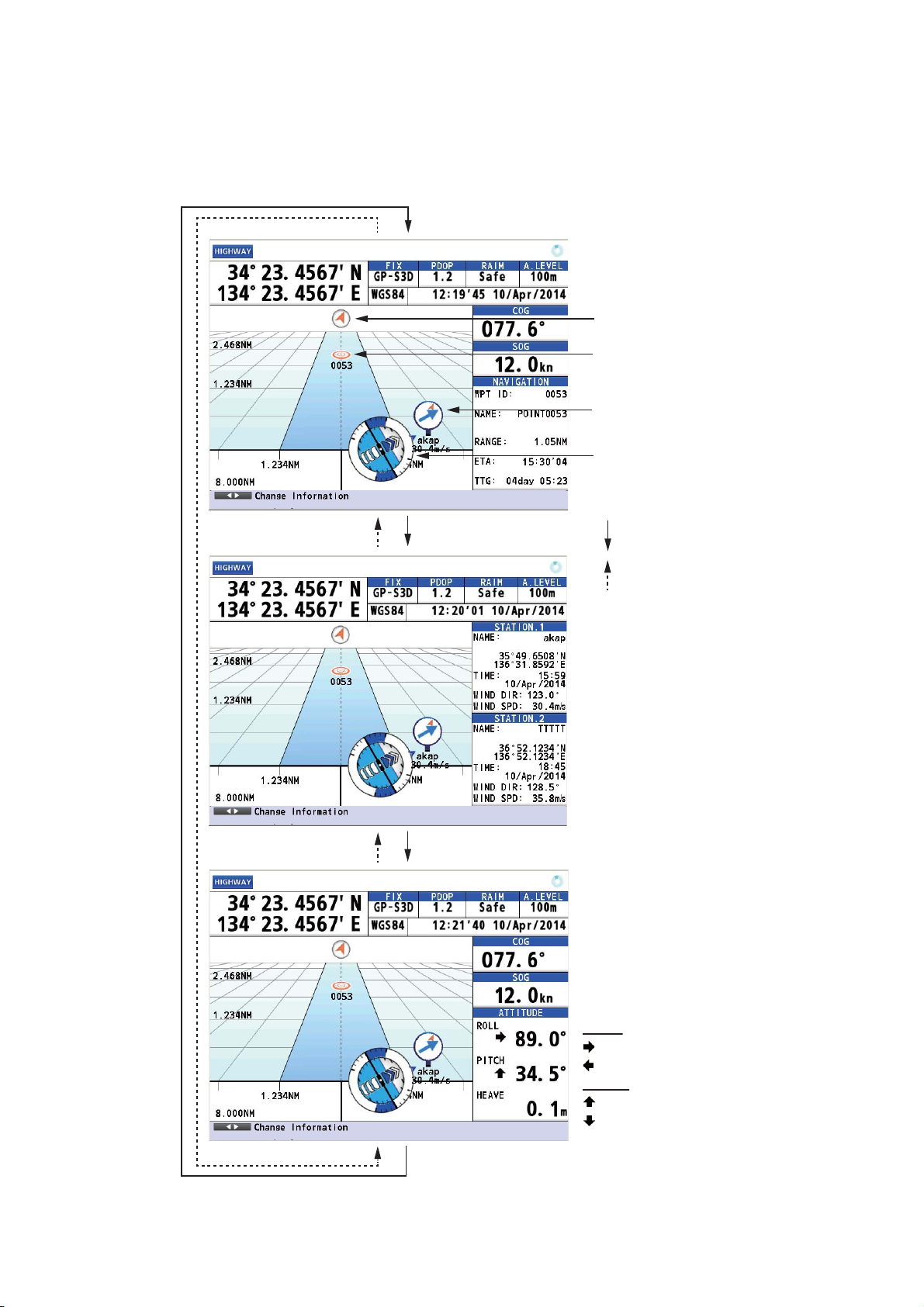
7. DISPLAYS
7.2 Highway Display
The highway display provides a 3-D view of own ship’s progress toward destination.
Use the cursorpad (W or X) to change the data at the right-hand of the display.
North mark
Waypoint
Weather data (wind
direction and speed)
(See paragraph 2.1.14.)
Attitude gauge
(See page 9-3.)
: Press the ► key.
: Press the ◄ key.
When weather data is
received from the
beacon station.
When the data for roll,
pitch or heave is
received.
7-4
ROLL
: Starboard
: Port
PITCH
: Up
: Down
Page 63

7.3 Course Display
The course display shows the course information. The information at the right-hand
side of the display is different between autopilot connection and no autopilot connection.
Bearing from own ship
to destination waypoint
7. DISPLAYS
Autopilot mode
Autopilot-set heading
Rudder angle
Course angle
Speed over ground
Heading (for autopilot)
With autopilot connection
Velocity to destination
Trip distance
Cross track distance indication
Estimated time and date
of arrival
Required time to destination
Required time to next
destination
Range
No autopilot connection
7-5
Page 64

7. DISPLAYS
7.4 Data Display
The data display shows the navigation data. Use the cursorpad (W or X) to change
the data to display.
Own ship’s position*
Speed over ground
Range
Heading
Course over ground
Own ship’s position*
Route total distance
Estimated time of arrival
at the final destination
Estimated time of
arrival and planned
estimated time of arrival
at destination
Time to go to destination
Press the ◄ or ► key.
*: Shows the ship’s position adjusted with the setting position offset
based on the selected datum (refer to paragraph 9.3.5).
7-6
How to customize the display
You can arrange the data to display and show the data in the order desired. Availability
of data depends on the sensors connected.
1. Press the MENU/ESC key to open the main menu.
2. Select [8 System Setting] then [2 Plotter].
Page 65

3. Select [4 User Defined].
4. Select [1 Custom 1].
7. DISPLAYS
• [TTG]: Time to go to destination
• [TRIP]: Distance to go to destination
• [TRIP TIME]: Time elapsed since the destination
was set
• [Route TTG]: Time to go to the final destination
• [VTD]: Velocity to destination
• [ETA/ETA(Plan)]: ETA is estimated time of arrival
at destination. ETA(Plan) is planned estimated
time of arrival at destination.
5. Select an option.
6. Repeat steps 4 and 5 to select options for [2 Custom 2] to [8 Custom 8].
7. Press the MENU/ESC key to close the main menu.
Press the ◄
or ► key.
Custom 1 Custom 2
Custom 3 Custom 4
Custom 5 Custom 6
Custom 7 Custom 8
7-7
Page 66

7. DISPLAYS
A
How to zoom information
1. Press the CURSOR ON/OFF key. An information is highlighted as follows.
n information
highlighted
2. Use the cursorpad (S or T) to select the information to zoom in. SOG is highlight-
ed in the following example.
3. Press the ZOOM IN key to zoom in the SOG information.
To go to the original display, press the ZOOM OUT key.
4. Press the CURSOR ON/OFF key to deselect the SOG information.
7-8
Page 67

8. ALERTS
“Alert” is a generic name for a notice to any unusual or potentially dangerous situation
generated within the system. There are two types of alerts, warning and caution.
Warning: Conditions or situations which require immediate attention for precautionary
reasons.
Caution: Awareness of a condition which continues to require attention out of the ordinary consideration of the situation.
8.1 Overview
The GP-170 has eight types of alerts as follows:
ID Message Type Meaning
010
or
401010*
• D3D turned to 3D.
• D3D turned to 2D.
• D2D turned to 3D.
• D2D turned to 2D.
• S3D turned to 3D.
• S3D turned to 2D.
• S2D turned to 3D.
• S2D turned to 2D.
• D3D turned to "No Fix".
• D2D turned to "No Fix".
• S3D turned to "No Fix".
• S2D turned to "No Fix".
Caution The positioning system turns from
DGPS to GPS.
Abbreviated messages:
• D3D → 3D.
• D3D → 2D.
• D2D → 3D.
• D2D → 2D.
• S3D → 3D.
• S3D → 2D.
• S2D → 3D.
• S2D → 2D.
• D3D → "No Fix".
• D2D → "No Fix".
• S3D → "No Fix".
• S2D → "No Fix".
210 HDOP exceeded. Caution The value of HDOP (Horizontal Di-
lution of Precision) is 4 or above.
HDOP threshold being permanently set to 4.
211 No calculation of position.
Abbreviated messages:
No calculation of POSN.
212 Loss of position. Warning No positioning data.
Warning The signal from core is not received
for three seconds.
8-1
Page 68

8. ALERTS
ID Message Type Meaning
213 Loss of differential signal.
Abbreviated messages:
Loss of DGNSS signal.
215 Differential integrity status.
Abbreviated messages:
DGNSS integrity status.
009
or
401009*
950
or
401950*
Antenna short-circuited.
Abbreviated messages:
ANT short-circuited.
Communication error with
BAM.
Caution More than 10 seconds have passed
since the last beacon message is
received.
Caution The beacon station selected auto-
matically is unhealthy.
Warning The antenna has shorted out.
Caution Communication error with alert
management system
*: When the alert mode is set to [Alert I/F 2] (only for serviceman), the alert ID number
is displayed in six digits.
Note: When a warning is not acknowledged within three minutes, the warning is repeated.
When an alert condition occurs, the buzzer sounds (except for a caution) and the
name of the alert appears at the bottom of the display.
Example 1: Warning
8-2
Ship’s position,
ship’s mark and
time of position fix
are displayed in red
for the caution “210
HDOP exceeded”.
Example 2: Caution
Page 69
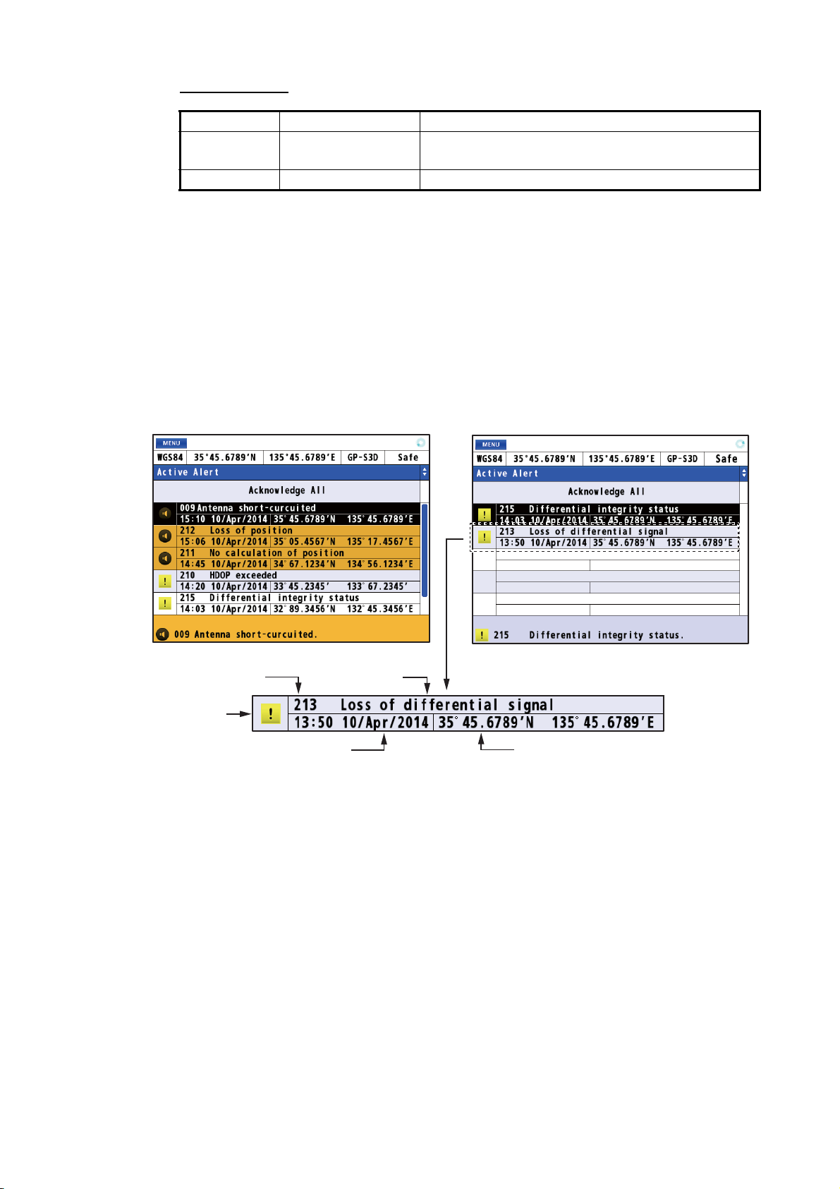
Alert category
Type Icon Visual indication
Warning Circle • Acknowledged: Yellow-orange
Caution Square Yellow
For details, see page AP-8.
8.2 Alert List
The alert list shows all currently violated alerts and state of acknowledgment. All unacknowledged alerts are shown, even those whose reason for alert has passed (except for a caution).
1. Press the MENU/ESC key to open the main menu.
2. Select [5 Alert] then [1 Active Alert] to show the alert list. Unacknowledged alerts
flash (except for a caution).
8. ALERTS
• Not acknowledged: Yellow-orange, flashing
Not acknowledged
Alert number
Alert icon
Date and time of occurrence
3. Press the MENU/ESC key to close the alert list.
Alert name
Acknowleded
Position of occurrence
8-3
Page 70

8. ALERTS
8.3 Alert Log
The alert log shows the latest 50 alerts. When the log becomes full, the oldest entry is
erased to make room for current alerts.
1. Press the MENU/ESC key to open the main menu.
2. Select [5 Alert] then [4 Alert Log] to show the alert log.
Priority
Alert number
Alert name
Date and time of
acknowledgement
Date and time
of occurrence
List no.
3. Press the MENU/ESC key to close the alert log.
8.4 How to Acknowledge Alerts
With the ACK/DELETE key
When an alert condition occurs, the buzzer sounds (except for a caution) and the
name of the alert appears at the bottom of the display. Press the ACK/DELETE key
to acknowledge the alert. The buzzer stops for a warning. If multiple alerts are violated, a high-priority alert is acknowledged in order.
How to acknowledge an alert from the alert list
1. Open the alert list (see section 8.2).
2. Use the cursorpad (S or T) to select the alert to acknowledge then press the NU/
CU ENT key.
Date and time
when occurrence
factor is gone
Position of occurrence
8-4
How to acknowledge all alerts from the alert list
1. Open the alert list (see section 8.2).
2. Use the cursorpad (S) to select [Acknowledge All] then press the NU/CU ENT
key.
Page 71

9. OTHER FUNCTIONS
This chapter describes menu items not described in other chapters.
9.1 Unit Setup Menu
You can set the units of measurement for distance, depth and water temperature.
1. Press the MENU/ESC key to open the main menu.
2. Select [8 System Setting] then [3 Unit Setup].
3. Distance: Select [1 Unit of Distance].
Depth: Select [2 Unit of Depth].
Water temperature: Select [3 Unit of Temperature].
Distance Depth Water temperature
4. Select the unit.
5. Press the MENU/ESC key to close the main menu.
Note: When changing the units of measurement, the setting values for the notice setting can exceed the setting range. Reset the values (see paragraph 4.1.1 and
chapter 6).
9.2 Correction, Offset Menu
Position offset
You may apply an offset to the position to further refine its accuracy.
1. Press the MENU/ESC key to open the main menu.
2. Select [8 System Setting] then [4 Correction, Offset].
9-1
Page 72

9. OTHER FUNCTIONS
3. Select [1 Position Offset].
4. Enter the offset value with the numeric keys. Mark your ship’s position on the chart
to calculate the error with latitude and longitude, and enter the values. To change
the coordinate, select "N" or "E" then press one of keys from 0 to 9.
5. Move the cursor to [Enter] then press the NU/CU ENT key.
6. Press the MENU/ESC key to close the main menu.
Note: When you set the position offset, the Datum indication changes to 999 (User
Defined).
Time difference
You can display time in UTC or local. For local time, enter the time difference between
local time and UTC.
1. Press the MENU/ESC key to open the main menu.
2. Select [8 System Setting] then [4 Correction, Offset].
3. Select [2 Local Time].
4. Select [1 Off] or [2 Manual Input].
[Off]: Uses UTC (Universal Time Coordinated). Go to
step 7.
[Manual Input]: Sets the time manually. Go to step 5.
5. Enter the difference time with the numeric keys. (If
necessary, switch + and - with pressing one of
keys from 0 to 9.)
6. Move the cursor to [Enter] then press the NU/CU
ENT key.
7. Press the MENU/ESC key to close the main menu.
“LOCAL means the time
is local time.
9-2
Page 73

Ship size and antenna position
1. Press the MENU/ESC key to open the main menu.
2. Select [8 System Setting] then [4 Correction, Offset].
3. Select [3 Ship Size/Antenna Position].
1
2
9. OTHER FUNCTIONS
: Set the width and length of your ship. Enter the values as correct as possible
1
because these values influence the output sentence “POS”. Note that these values
are the upper limits for the values of 2 .
: Set the mounting location for the antenna unit.
2
X: The horizontal distance from the reference position “0” to the antenna position.
Y: The forward distance from the reference position “0” to the antenna position.
Z: The height from the ship bottom to the antenna unit.
4. Enter the value for each item with the numeric keys. Refer to the figure at the righthand of the display.
5. Move the cursor to [Enter] then press the NU/CU ENT key.
6. Press the MENU/ESC key to close the main menu.
Attitude gauge
The attitude gauge is displayed when the data for roll, pitch or heave is received.
1. Press the MENU/ESC key to open the main menu.
2. Select [8 System Setting] then [4 Correction, Offset].
3. Select [4 Attitude Gauge].
4. Select [1 On] or [2 Off].
[On]: Displays the attitude gauge (see the illustration in "Highway Display" on
page 1-7) instead of the ship’s icon on the highway display. When the data for roll,
pitch or heave is not received, the ship’s icon is displayed.
[Off]: Hides the attitude gauge on the highway display.
5. Press the MENU/ESC key to close the main menu.
9-3
Page 74

9. OTHER FUNCTIONS
9.3 GNSS Menu
9.3.1 How to select the positioning system
1. Press the MENU/ESC key to open the main menu.
2. Select [8 System Setting] then [5 GNSS].
3. Select [1 Method].
4. Select [1 GPS].
5. Press the MENU/ESC key to close the main
menu.
No. 2, 3 and 4
are reserved
for future use.
9.3.2 How to set the time for smoothing of position, speed and speed average
Position smoothing: When the receiving condition is unfavorable, the GPS fix may
change randomly, even if the ship is dead in water. This change can be reduced by
smoothing the raw GPS fixes. The higher the setting the more smoothed the raw data,
however too high a setting slows response time to change in latitude and longitude.
This is especially noticeable at high ship’s speeds. Increase the setting if the GPS fix
changes randomly.
Speed smoothing: During position fixing, ship’s velocity (speed and course) is directly measured by receiving GPS satellite signals. The raw velocity data may change randomly depending on receiving conditions and other factors. You can reduce this
random variation by increasing the smoothing. Like with latitude and longitude
smoothing, the higher the speed and course smoothing the more smoothed the raw
data. If the setting is too high, however, the response to speed and course change
slows.
9-4
Speed average: This speed is used to calculate the COG and SOG on the data dis-
play (see page 7-6).
1. Press the MENU/ESC key to open the main menu.
2. Select [8 System Setting] then [5 GNSS].
Page 75

3. Select [2 GPS Smoothing].
4. Select [1 Position], [2 Speed] or [3 Speed Average].
5. Enter the time for smoothing with the numeric
keys.
6. Move the cursor to [Enter] then press the NU/
CU ENT key.
7. Press the MENU/ESC key to close the main menu.
9.3.3 How to set the positioning condition
Satellite elevation
9. OTHER FUNCTIONS
You can set the minimum elevation of satellites to use to fix position.
1. Press the MENU/ESC key to open the main menu.
2. Select [8 System Setting] then [5 GNSS].
3. Select [3 Condition].
4. Select [1 Elevation Mask].
5. Enter the elevation with the numeric keys.
6. Move the cursor to [Enter] then press the NU/
CU ENT key.
7. Press the MENU/ESC key to close the main
menu.
Disable satellite
Every GPS satellite is broadcasting abnormal satellite number(s) in its Almanac,
which contains general orbital data about all GPS satellites. Using this information, the
GPS receiver automatically eliminates any malfunctioning satellite from the GPS satellite schedule. However, the Almanac sometimes may not contain this information.
You can disable an inoperative satellite manually. Enter satellite numbers (up to three
satellites) in three digits.
1. Press the MENU/ESC key to open the main menu.
2. Select [8 System Setting] then [5 GNSS].
3. Select [3 Condition].
9-5
Page 76

9. OTHER FUNCTIONS
4. Select [2 Not Used GPS].
5. Enter the satellite numbers with the numeric
keys.
6. Move the cursor to [Enter] then press the NU/
CU ENT key.
7. Press the MENU/ESC key to close the main
menu.
Core filter
1. Press the MENU/ESC key to open the main menu.
2. Select [8 System Setting] then [5 GNSS].
3. Select [3 Condition].
4. Select [5 Core Filter].
5. Select [1 No] or [2 Yes].
[No]: The tracking sensitivity is better than [Yes], however the ship’s
track is traced less smoothly than [Yes].
[Yes]: The ship’s track is traced smoother than [No], however the tracking sensitivity is not as good as [No].
6. Press the MENU/ESC key to close the main menu.
9.3.4 How to select the RAIM function
RAIM (Receiver Autonomous Integrity Monitoring) is a diagnostic function which tests
the accuracy of the GPS signal. To use the RAIM function, enter the range (from own
ship in meters) for which you want to know position confidence. The receiver estimates position confidence using range value and detected satellite error, and displays
(provided the RAIM function is active) the results as one of three levels of position confidence, at the top right-hand corner of the display. The three levels are as follows:
• Safe: GPS signal is normal. The positioning accuracy satisfies the setting value.
• Caution: RAIM accuracy cannot be calculated. (Signals from more than five GPS
satellites are necessary.) The positioning accuracy does not satisfy the setting value.
• Unsafe: GPS signal is abnormal, therefore the positioning accuracy is not reliable.
1. Press the MENU/ESC key to open the main menu.
2. Select [8 System Setting] then [5 GNSS].
3. Select [4 RAIM].
9-6
4. Select [1 Setting].
5. Select [1 On] or [2 Off].
[On]: Use RAIM function. Go to step 6.
[Off]: Don’t use RAIM function. Go to step 9.
Page 77

6. Select [2 Accuracy Level].
7. Enter the distance with the numeric keys.
8. Move the cursor to [Enter] then press the NU/
CU ENT key.
9. Press the MENU/ESC key to close the main
menu.
9.3.5 How to select the datum
Your unit is programmed to recognize most of the major chart systems of the world.
Although the WGS84 system, the GPS standard, is now widely used other categories
of charts still exist. Select the same datum which is used in your nautical charts. Select
[WGS84] (default setting), [WGS72] or [Other] (enter the datum number).
1. Press the MENU/ESC key to open the main menu.
2. Select [8 System Setting] then [5 GNSS].
3. Select [5 Datum].
4. Select an option. For [6 Other], go to step 5. For others, go to
step 7.
9. OTHER FUNCTIONS
5. Enter the datum number with the numeric
keys.
6. Move the cursor to [Enter] then press the NU/
CU ENT key.
7. Press the MENU/ESC key to close the main
menu.
9.3.6 How to set the initial position
You can set the initial position to use when the equipment is restarted.
1. Press the MENU/ESC key to open the main menu.
2. Select [8 System Setting] then [5 GNSS].
3. Select [6 Init Position].
4. Enter the position with the numeric
keys. To change the coordinate, select
"N" or "E" then press one of keys from
0 to 9.
5. Move the cursor to [Enter] then press
the NU/CU ENT key.
6. Press the MENU/ESC key to close the main menu.
9-7
Page 78

9. OTHER FUNCTIONS
9.3.7 How to set the positioning cycle
You can set the positioning cycle. Position is updated faster with the 5Hz or 10Hz setting, however the accuracy may not be as good as with the 1Hz setting. It is recommended to use the 1Hz setting for vessels other than high speed craft.
1. Press the MENU/ESC key to open the main menu.
2. Select [8 System Setting] then [5 GNSS].
3. Select [9 Cycle].
4. Select [1 1Hz], [2 5Hz] or [3 10Hz]. The confirmation message appears.
5. Select [1 Yes]. The GP-170 restarts.
9.3.8 How to turn the anti-multipath mode on/off
You can prevent multipath, reflection of the satellite signal by some object, to prevent
position “jump”.
1. Press the MENU/ESC key to open the main menu.
2. Select [8 System Setting] then [5 GNSS].
3. Select [0 Anti-Multipath Filter].
4. Select [1 On] or [2 Off]. The confirmation message appears.
5. Select [1 Yes]. The GP-170 restarts.
9-8
Page 79

9. OTHER FUNCTIONS
9.4 Beacon/SBAS Menu
This menu sets the beacon and SBAS.
9.4.1 How to select the differential corrections to use
1. Press the MENU/ESC key to open the main menu.
2. Select [8 System Setting] then [6 Beacon/SBAS].
3. Select [1 Mode].
4. Select an option.
[GNSS]: Uses neither beacon nor SBAS for positioning.
[GNSS+SBAS (+QZSS)]: Uses SBAS and QZSS.
[GNSS+Internal Beacon]*: Uses internal beacon.
[GNSS+Beacon (Data1, Data2 or Data4)]*: Uses
external beacon.
[Auto]: Switches mode among differential (beacon), SBAS and no use. The priority is Differential (beacon) > SBAS > No use.
* : See the table below.
Menu item
GNSS+Internal Beacon Available Not available
GNSS+Beacon (Data1, Data2 or Data4) Not available Available
5. Press the MENU/ESC key to close the main menu.
9.4.2 How to set SBAS and beacon
SBAS
With internal
beacon receiver
Without internal
beacon receiver
1. Press the MENU/ESC key to open the main menu.
2. Select [8 System Setting] then [6 Beacon/SBAS].
3. Select [2 SBAS Search].
4. Select [1 Auto] or [2 Manual].
[Auto]: Automatically selects the satellite on the highest elevation among available
satellites. Go to step 7.
[Manual]: Selects the satellite manually. Go to step 5.
9-9
Page 80

9. OTHER FUNCTIONS
5. Enter the satellite number with the numeric
keys (setting range: 120 to 138).
6. Move the cursor to [Enter] then press the NU/
CU ENT key.
7. Press the MENU/ESC key to close the main
menu.
Beacon
1. Press the MENU/ESC key to open the main menu.
2. Select [8 System Setting] then [6 Beacon/SBAS].
3. Select [3 Beacon Station].
4. Select [1 Auto], [2 Set Parameter] or [3 Select
Station ID].
[Auto]: Automatically selects the nearest station
among available stations. Go to step 8.
[Set Parameter]: Selects the station with entering the frequency or selecting the
bit rate. Go to step 5.
[Select Station ID]: Selects the station from the station list (requires the internal
beacon receiver). Go to step 7.
5. Select [1 Frequency] or [2 Bit Rate].
6. For [Frequency]
to [Enter] then press the NU/CU ENT key.
For [Bit Rate]
Go to step 8.
7. Use the cursorpad (S or T) to select the station ID then press the NU/CU ENT
key.
8. Press the MENU/ESC key to close the main menu.
, enter the frequency with the numeric keys and move the cursor
, select the bit rate from five options.
9.4.3 How to open the station data
Station database
Note: This menu requires the internal beacon receiver.
1. Press the MENU/ESC key to open the main menu.
2. Select [8 System Setting] then [6 Beacon/SBAS].
9-10
Page 81

9. OTHER FUNCTIONS
3. Select [4 Station Database] to show the [Station List] for 1020 station data.
Enter the station no.
(e.g. “0001”) with the
numeric key then press
the NU/CU ENT key to
display the information
of the selected station
at the right side of the
screen.
4. Press the MENU/ESC key to close the main menu.
Registered stations
You can register up to 20 beacon stations.
Note: This menu requires the internal beacon receiver.
1. Press the MENU/ESC key to open the main menu.
2. Select [8 System Setting] then [6 Beacon/SBAS].
3. Select [5 Registered Stations] to show the [Edit Station Information] list.
9-11
Page 82

9. OTHER FUNCTIONS
4. Use the cursorpad (S or T) to select ID no. then press the NU/CU ENT key.
5. Edit the name, position, frequency or bit rate.
6. Press the MENU/ESC key to close the main menu.
Disable satellite
You can disable a maximum of three satellites.
1. Press the MENU/ESC key to open the main menu.
2. Select [8 System Setting] then [6 Beacon/SBAS].
3. Select [6 Not Used Satellite].
4. Select [1 SBAS] or [2 QZSS].
5. Enter the disable satellite numbers with the
numeric keys (setting range: 120 to 138 for
SBAS, 183 to 187 and 193 to 197 for QZSS).
6. Move the cursor to [Enter] then press the NU/
CU ENT key.
7. Press the MENU/ESC key to close the main
menu.
9.5 Language
9-12
The available languages are English and Japanese.
1. Press the MENU/ESC key to open the main menu.
2. Select [8 System Setting] then [1 Language].
3. Select a language.
4. Press the MENU/ESC key to close the main menu.
Page 83

9.6 I/O Menu
Besides its fundamental function of displaying position, the GP-170 can also output
various data to external equipment. Before outputting data to external equipment, first
determine what data the external equipment requires. Output only necessary data to
ensure data will be output correctly.
All data transmitted by marine electronics equipment are prefixed with a two character
code called a talker. The same talker must be shared by the transmitting and receiving
equipment to transmit and receive data successfully.
9.6.1 How to set the output 1, 2, 3 or 4
1. Press the MENU/ESC key to open the main menu.
2. Select [7 I/O].
9. OTHER FUNCTIONS
3. Select [1 Output Data1].
4. Select [1 Mode].
5. Select [1 IEC/NMEA] or [2 RTCM].
[IEC/NMEA]: NMEA sentence output
[RTCM]: Binary output
6. Select [2 Format].
7. Select [1 IEC 61162-1 Ed.4], [2 IEC 61162-1 Ed.3],
[NMEA V2.0] or [NMEA V1.5].
8. Select [3 Talker].
9. Select [1 GP] or [4 GN].
No. 2 and 3 are reserved
for future use.
9-13
Page 84

9. OTHER FUNCTIONS
10. Select [4 BPS].
11. Select [1 4800 bps], [2 9600 bps] or [3 38400 bps].
12. Select [5 Sentence].
13. Use the cursorpad to select the sentence then press the NU/CU ENT key.
14. Use the cursorpad (W or X) to select the TX interval. TX interval is available in [-
- -] (off), [0.1s]*, [0.2s]*, [1s], [2s], [3s], [4s], [5s], [6s], [10s], [15s], [20s], [30s],
[60s] and [90s].
*: Only for GGA, GLL, GNS, RMC and VTG when selecting [38400 bps] at step 11.
15. Press the NU/CU ENT key.
Note 1: Keep the Load Rate below 100% when setting the TX intervals. The TX
interval for other than the ZDA sentence cannot be guaranteed if the rate exceeds
100%.
Note 2: For the TX interval of [0.1s] or [0.2s], set the positioning cycle (refer to
paragraph 9.3.7) as follows:
• For [0.1s], set the positioning cycle at 10Hz.
• For [0.2s], set the positioning cycle at 5Hz or 10Hz.
16. Set [2 Output Data2], [3 Output Data3] and [4 Output Data4] as well.
17. Press the MENU/ESC key to close the main menu.
9.6.2 How to set the Ethernet
1. Press the MENU/ESC key to open the main menu.
9-14
2. Select [7 I/O] then [5 Ethernet].
3. Select [1 Sentence].
4. Use the cursorpad to select the sentence
then press the NU/CU ENT key.
5. Use the cursorpad (W or X) to select the TX
interval. TX interval is available in [- - -] (off),
[0.1s]*, [0.2s]*, [1s], [2s], [3s], [4s], [5s], [6s],
[10s], [15s], [20s], [30s], [60s] and [90s].
*: Only for GGA, GLL, GNS, RMC and VTG.
Page 85

9. OTHER FUNCTIONS
6. Press the NU/CU ENT key.
Note: For the TX interval of [0.1s] or [0.2s], set the positioning cycle (refer to
paragraph 9.3.7) as follows:
• For [0.1s], set the positioning cycle at 10Hz.
• For [0.2s], set the positioning cycle at 5Hz or 10Hz.
7. Press the MENU/ESC key to close the sentence window.
8. Press the MENU/ESC key to open the main menu.
9. Select [7 I/O] then [5 Ethernet].
10. Select [2 IP ADR /Port].
11. Enter the IP address and port (setting range: 49152 to 65535) with the numeric
keys. When setting dual configuration (see section 9.7), set “239.192.000.004” for
IP address and “60004” for port.
12. Move the cursor to [Enter] then press the NU/CU ENT key.
13. Select [3 MP].
14. Select [1 Enable] or [2 Disable]. For [1 Enable], go to
step 15. For [2 Disable], go to step 18.
15. Select [4 MP IP ADR /Port].
16. Enter the MP IP address and port with the numeric keys.
17. Move the cursor to [Enter] then press the NU/CU ENT key.
18. Press the MENU/ESC key to close the main menu.
9.6.3 How to select the input data
1. Press the MENU/ESC key to open the main menu.
2. Select [7 I/O] then [6 Data Source Select].
3. Select [1 HDG].
4. Select the port for heading data. For [5 Ethernet], go to
step 5. For [1 Data1],
[2 Data2] or [4 Data4], go to step 6.
9-15
Page 86
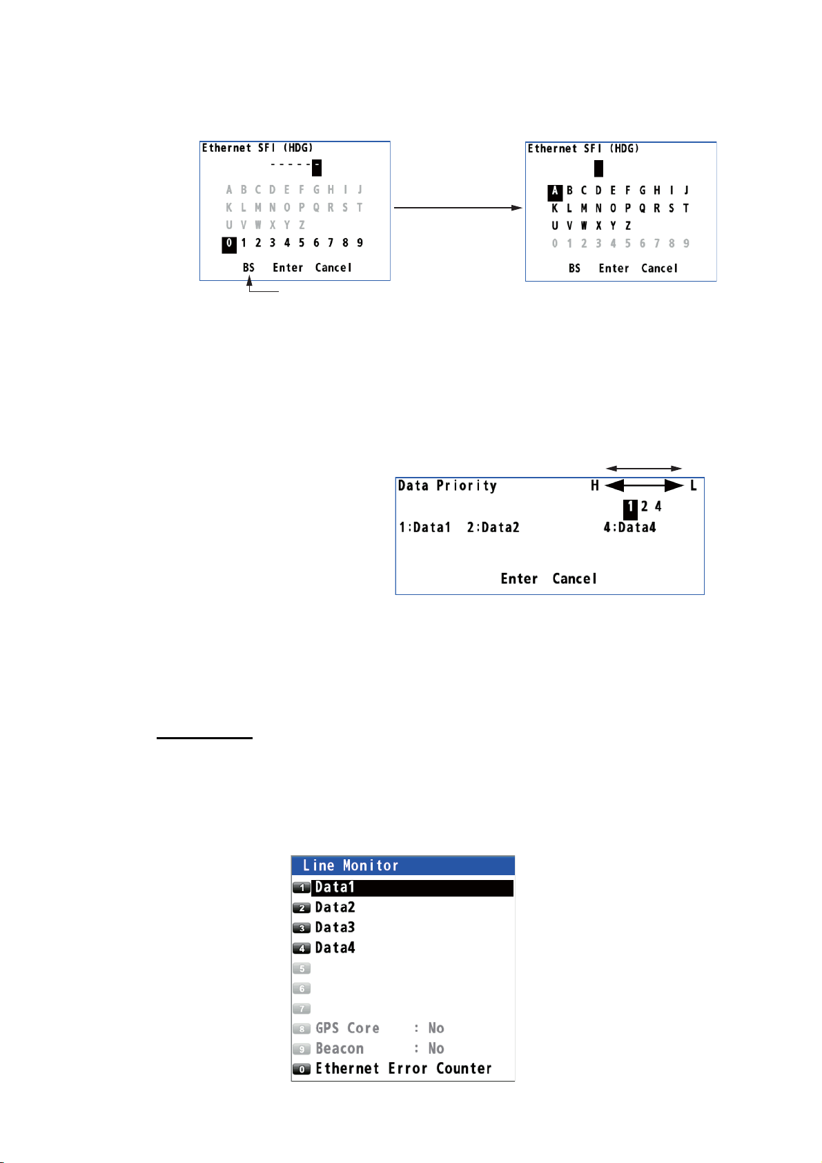
9. OTHER FUNCTIONS
5. When selecting [5 Ethernet], do the following:
1) Press the ACK/DELETE key to move the cursor to the leftmost of the input position.
2) Enter the Ethernet SFI with the cursorpad and the numeric keys (combination
of two alphabets and four numerals). SFI (System Function ID) is an identification code used by the system.
3) Move the cursor to [Enter] then press the NU/CU ENT key. Go to step 9.
Note: Set the SFI to eliminate overlap with other ones.
6. Select [1 HDG].
Press the
ACK/DELETE key.
Backspace
7. Select [7 User Priority].
8. Enter the priority for heading
data by data number. For example, to set the priority order
as Data1, Data2, Data4, enter
1, 2, 4.
9. Set the input data for [2 STW]
(speed through water),
[3 SST] (sea surface temperature) and [4 DPT] (water depth) as well.
10. Press the MENU/ESC key to close the main menu.
9.6.4 Line monitor log
Line monitor
The data output from the data ports (Data1 - Data4) can be monitored, and the data
can be saved to a USB flash memory.
1. Press the MENU/ESC key to open the main menu.
2. Select [7 I/O] then [7 Line Monitor].
High Low
9-16
Page 87

3. Select [Data1] (or 2, 3, 4).
9. OTHER FUNCTIONS
$YCMTW,027.32,C$GPZDA,012614.00,01,11,2012,09,00 42
$YCMTW,027.32,C$GPZDA,012614.00,01,11,2012,09,00 42
$YCMTW,027.32,C$GPZDA,012614.00,01,11,2012,09,00 42
$YCMTW,027.32,C$GPZDA,012614.00,01,11,2012,09,00 42
$YCMTW,027.32,C$GPZDA,012614.00,01,11,2012,09,00 42
$YCMTW,027.32,C$GPZDA,012614.00,01,11,2012,09,00 42
$YCMTW,027.32,C$GPZDA,012614.00,01,11,2012,09,00 42
$YCMTW,027.32,C$GPZDA,012614.00,01,11,2012,09,00 42
$YCMTW,027.32,C$GPZDA,012614.00,01,11,2012,09,00 42
$YCMTW,027.32,C$GPZDA,012614.00,01,11,2012,09,00 42
$GPZDA,012613.00,01,11,2012,-09,00 45
$GPDTM,W84,,00.0000,N,00.0000,E,,W84 41
$GPGGA,012614.00,0844.7963,S,11512.6084,E,2,6,0.7,15,M,,M,
, 78
$GPVTG,258.0,T,256.5,M,0.1,N,0.2,K,D 2E
$GPZDA,012613.00,01,11,2012,-09,00 45
$GPDTM,W84,,00.0000,N,00.0000,E,,W84 41
$GPGGA,012614.00,0844.7963,S,11512.6084,E,2,6,0.7,15,M,,M,
, 78
$GPVTG,258.0,T,256.5,M,0.1,N,0.2,K,D 2E
$GPZDA,012613.00,01,11,2012,-09,00 45
$GPDTM,W84,,00.0000,N,00.0000,E,,W84 41
$GPGGA,012614.00,0844.7963,S,11512.6084,E,2,6,0.7,15,M,,M,
, 78
$GPVTG,258.0,T,256.5,M,0.1,N,0.2,K,D 2E
$GPZDA,012613.00,01,11,2012,-09,00 45
$GPDTM,W84,,00.0000,N,00.0000,E,,W84 41
$GPGGA,012614.00,0844.7963,S,11512.6084,E,2,6,0.7,15,M,,M,
, 78
$GPVTG,258.0,T,256.5,M,0.1,N,0.2,K,D 2E
To save the log data to a USB flash memory, go to step 4. Otherwise, go to step 7.
4. Set a USB flash memory in the USB port.
Note 1: Do not use an encrypted USB flash memory.
Note 2: Keep water away from the unit when the USB flash memory is inserted.
The USB port is not waterproof while its cover is removed.
5. Press the NU/CU ENT key.
Note: Do not save the log from multiple ports simultaneously. The log data may
not be saved correctly depending on the specification or capacity of the USB flash
memory.
6. Press the NU/CU ENT key to complete the saving.
Note: Remove the USB flash memory after the saving is completed.
7. Press the MENU/ESC key to close the main menu.
Ethernet error counter
1. Press the MENU/ESC key to open the main menu.
2. Select [7 I/O] then [7 Line Monitor].
3. Select [0 Ethernet Error
Counter].
Press the ACK/DE-
LETE key to reset all
counts to 0.
4. Press the MENU/ESC
key to close the main
menu.
9-17
Page 88

9. OTHER FUNCTIONS
9.7 How to Set Dual Configuration
You can configure two dual differential GPS navigator systems and an interface unit.
1. Press the MENU/ESC key to open the main menu.
2. Select [7 I/O] then [8 Dual].
3. Select [1 No], [2 Serial (Data2)] or [3 Ethernet].
[No]: Don’t set dual configuration.
[Serial (Data2)]: Sets dual configuration using data2.
[Ethernet]: Sets dual configuration using Ethernet.
4. Press the MENU/ESC key to close the main menu.
9.8 How to Set ECDIS Sync Configuration
When connecting the ECDIS (FMD-3x00 series) via LAN, you can display the ECDISset monitored route on the display of the GP-170.
1. Press the MENU/ESC key to open the main menu.
2. Select [3 Navigation] then [4 ECDIS Sync].
3. Select [2 ECDIS IP ADR].
4. Enter the IP address for the connected ECDIS with the numeric keys.
5. Move the cursor to [Enter] then press the NU/CU ENT key.
6. Select [3 ECDIS SFI].
7. Press the ACK/DELETE key to move the cursor to the leftmost of the input position.
9-18
Press the
ACK/DELETE key.
Backspace
8. Enter the SFI for the connected ECDIS with the cursorpad and the numeric keys
(combination of two alphabets and four numerals).
9. Move the cursor to [Enter] then press the NU/CU ENT key.
Page 89

9. OTHER FUNCTIONS
10. Select [1 Mode].
11. Select [2 On].
Note: When selecting [2 On], you can not set a destination on the GP-170.
12. Press the MENU/ESC key to close the main menu.
To turn the synchronization off, select [1 Off] at step 11.
Note 1: When selecting [1 Off] during the synchronization with the ECDIS, the destination is canceled on the GP-170.
Note 2: The GP-170 uses waypoint information from the ECDIS when they are
synched to one another. Therefore, some delay occurs between the arrival notice and
next waypoint. This is not an indication of malfunction but the difference of criterion for
waypoint updating between the ECDIS and the GPS receiver. If you do not need the
arrival notice on the GP-170, turn it off (see paragraph 6.2.1).
Note 3: The no. 100 route on the route list is reserved for the monitored route output
from the ECDIS. This route is automatically written over when the GP-170 receives a
new monitored route.
9.9 How to Change the User Password
You can set a four-character password to prevent unauthorized entry into certain
menus. The default setting is no password.
1. Press the MENU/ESC key to open the main menu.
2. Select [8 System Setting] then [2 Plotter].
3. Select [9 Password].
Note: The default setting is "0000", which
means no password is set. When the password is "0000", the [Input Password] screen
does not appear.
4. Enter the password (four characters) with the
numeric keys.
5. Enter the new password (four characters)
with the numeric keys.
6. Enter the password (four characters) with the numeric
keys again.
7. Press the NU/CU ENT key.
8. Press the MENU/ESC key to close the main menu.
9-19
Page 90

9. OTHER FUNCTIONS
9.10 How to Set the Demo Mode
A demo mode, which shows internally generated navigation data, is provided to acquaint you with the features of the GP-170. You can set the demo mode as follows:
1. Press the MENU/ESC key to open the main menu.
2. Select [8 System Setting] then [8 Demo].
3. Select [1 Parameter].
4. Enter each setting with the numeric keys refer to the left figure.
[Date]: Set the starting date and time in UTC.
[Position]: Set the starting position. To change the coordinate, select "N" or "E"
then press one of keys from 0 to 9.
[1. Direction]: Set the direction for translatory movement.
[2. SOG]: Set the speed for translatory movement in kn.
[3. Direction]: Select the direction for rotary motion from [CW] (clockwise) and
[CCW] (counterclockwise).
[4. Radius]: Set the radius for rotary motion in NM.
[5. Angular Speed]: Set the angular speed for rotary motion.
5. Move the cursor to [Start] then press the NU/CU ENT key. The equipment re-
starts. The icon (simulation) appears at the top left corner of the screen.
Note: To cancel the demo mode, turn the power off and on.
9-20
Page 91

10. MAINTENANCE, TROUBLESHOOTING
NOTICE
Do not apply paint, anti-corrosive sealant
or contact spray to plastic parts or
equipment coating.
Those items contain products that can
damage plastic parts and equipment coating.
10.1 Maintenance
Regular maintenance is important to maintain performance. Check the following
points to help maintain performance.
• Check that connectors on the rear panel are firmly tightened and free of rust.
• Check that the ground system is free of rust and the ground wire is tightly fastened.
• Check that battery terminals are clean and free of rust.
• Check if the antenna unit is damaged. If damaged, replace.
• Dust or dirt may be removed from the cabinet with a soft cloth. Water-diluted mild
detergent may be used if desired. DO NOT use chemical cleaners to clean the display unit; they may remove paint and markings.
• Wipe the LCD carefully to prevent scratching, using tissue paper and an LCD clean-
er. To remove dirt or salt deposits, use an LCD cleaner, wiping slowly with tissue
paper so as to dissolve the dirt or salt. Change paper frequently so the salt or dirt
will not scratch the LCD. Do not use solvents such as thinner, acetone or benzene
for cleaning. Also, do not use degreaser or antifog solution, as they can strip the
coating from the LCD.
Life of LCD
The life of the LCD is approximately 60,000 hours. The actual number of hours depends on ambient temperature and humidity. When the brilliance cannot be raised sufficiently, ask your dealer about replacement.
10-1
Page 92

10. MAINTENANCE, TROUBLESHOOTING
10.2 Fuse Replacement
WARNING
Use the proper fuse.
A wrong fuse can damage the equipment
and cause fire.
The fuse (type: FGBO-A 125V 3A PBF, code no.: 000-155-850-10) in the power cable
protects against overvoltage and equipment trouble. If you cannot turn on the power,
first check the fuse. If the fuse has blown, replace the fuse with the specified fuse. If
the fuse blows again after replacement, contact your dealer.
10.3 Troubleshooting
This section provides simple troubleshooting procedures which the user can follow to
restore normal operation. If you cannot restore normal operation, do not attempt to
check inside the unit. Any trouble should be referred to a qualified technician.
Symptom Remedy
You cannot turn on the power. • Check for damaged power cable and connector.
• Check if the power cable is firmly fastened.
• Check the battery for proper voltage output.
• Check if the fuse in the power cable has blown.
No picture appears.
There is no response when a
key is pressed.
Position is not fixed. • Check if the antenna connector is firmly fastened.
Position is wrong. • Check if the correct geodetic chart system is selected
Bearing is wrong. Check the magnetic variation on the [8 System Setting] -
Data are not transmitted to
external equipment.
Adjust the brilliance using the BRILL key.
Turn off and on the power. If no change, ask your dealer.
• Check the number of satellites on the integrity display.
If there are two or less, check for obstructions between
antenna unit and satellites.
• Clear the GPS memory on the [8 System Setting] -
[9 Clear Memory] - [2 Clear GPS] menu.
on the [8 System Setting] - [5 GNSS] - [5 Datum]
menu.
• Enter the position offset on the [8 System Setting] -
[4 Correction, Offset] - [1 Position Offset] menu.
[2 Plotter] - [2 Magnetic Variation] menu.
• Check if the data format is correct on the [7 I/O] menu.
• The TX interval may be set to off. Select the proper in-
terval.
• Check the appropriate settings on the external equip-
ment.
• Check the connections:
GP-170
TD4-A RD4-A
TD4-B RD4-B
External equipment
10-2
Page 93
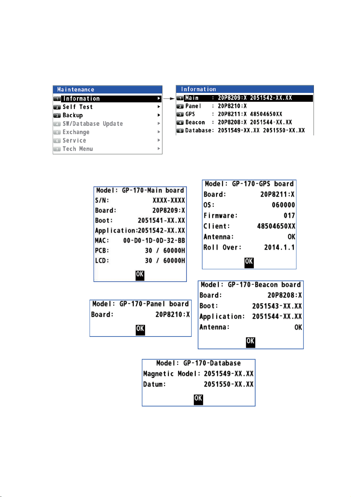
10.4 Equipment Information
You can display information about this equipment from the menu.
1. Press the MENU/ESC key to open the main menu.
2. Select [6 Maintenance] then [1 Information].
3. Select [1 Main], [2 Panel], [3 GPS], [4 Beacon] (requires internal beacon receiver)
or [5 Database].
10. MAINTENANCE, TROUBLESHOOTING
X: Board version no.
XX: Program version no.
GPS
Main
Panel
Beacon
Database
4. Press the NU/CU ENT key to close each information window.
5. Press the MENU/ESC key to close the main menu.
10-3
Page 94

10. MAINTENANCE, TROUBLESHOOTING
10.5 Self Test
The self test checks the ROM, RAM, input/output data, GPS core, Beacon core, keyboard and LCD performance. The user can do the tests to help the service technician
in troubleshooting.
Memory test
1. Press the MENU/ESC key to open the main menu.
2. Select [6 Maintenance] then [2 Self Test].
3. Select [1 Memory Test]. The test results are displayed as "OK", "NG" (No Good)
or "– –". If any NG is displayed, contact your dealer. The test result of DATA3,
checked using a dedicated connector at the factory, is normally displayed as "--".
10-4
4. Press the MENU/ESC key to close the memory test window.
Page 95

10. MAINTENANCE, TROUBLESHOOTING
Keyboard test
1. Press the MENU/ESC key to open the main menu.
2. Select [6 Maintenance] then [2 Self Test].
3. Select [2 Keyboard Test].
4. Press each key one by one. A key's corresponding location on the display turns
blue if the key is normal.
5. Press the MENU/ESC key three times to close the keyboard test window.
LCD test
1. Press the MENU/ESC key to open the main menu.
2. Select [6 Maintenance] then [2 Self Test].
3. Select [3 LCD Test]. The operation instructions display opens.
10-5
Page 96

10. MAINTENANCE, TROUBLESHOOTING
4. Press the NU/CU ENT key. Each press of this key changes the LCD pattern in the
sequence shown below.
Black
Blue
Note: You can cancel the test at any time by pressing the MENU/ESC key.
5. Press the MENU/ESC key to close the test pattern window.
White
Checker board
Red
RGB gradation
Operation instructions
Green
display
Automatic test
The memory, keyboard and LCD tests are automatically tested.
1. Press the MENU/ESC key to open the main menu.
2. Select [6 Maintenance] then [2 Self Test].
3. Select [4 Automatic Test]. The GP-170 automatically repeats the following sequence.
Information screen (refer to section 10.4) →Memory → Keyboard → LCD
Note 1: You can cancel the test at any time by pressing the MENU/ESC key.
Note 2: The test stops if the check result for an item other than [Data3] is "NG" or
"– –".
4. Press the MENU/ESC key to close the automatic test window.
10.6 Backup
The GP-170 can save or load the settings and registered data.
1. Set a USB flash memory in the USB port.
Note 1: Do not use an encrypted USB flash memory.
Note 2: Keep water away from the unit when the USB flash memory is inserted.
The USB port is not waterproof while its cover is removed.
2. Press the MENU/ESC key to open the main menu.
3. Select [6 Maintenance] then [3 Backup].
10-6
Page 97

10. MAINTENANCE, TROUBLESHOOTING
4. Select [1 Backup User Setting], [2 Load User Setting], [3 Import GPX (Overwrite)],
[4 Import GPX (Addition)] or [5 Export GPX].
[Backup User Setting]: Saves the current settings to a USB flash memory.
[Load User Setting]: Loads the saved settings from a USB flash memory.
[Import GPX (Overwrite)]: Imports the GPX data (marks, waypoints and routes)
from a USB flash memory. The GPX data in the GP-170 are deleted.
[Import GPX (Addition)]: Imported data is added to the GPX data in the GP-170.
(You can store a maximum of 2,000 marks, 100 routes, and 1,000 waypoints.)
[Export GPX]: Exports the GPX data (marks, waypoints and routes) in the GP-170
to a USB flash memory.
The confirmation message appears.
5. Select [1 Yes]. The message "Now Processing.... "appears.
After the process is complete, the GP-170 operates as follows, or do the following
according the menu item selected at step 4:
• [Backup User Setting]: The message window automatically closes.
• [Load User Setting], [Import GPX (Overwrite)], [Import GPX (Addition)]: The
GP-170 restarts.
• [Export GPX]: After the message window shows 100%, press the MENU/ESC
key to close the message window.
Note: If a USB flash memory is not set, the following message appears.
Note: Route no. 100 is reserved for the monitored route sent from an ECDIS. A route
imported from a USB flash memory may also be assigned this number when that route
becomes the 100th route registered in the GP-170. Whenever a monitored route is received, route no. 100 is written over to import the monitored route.
10-7
Page 98

10. MAINTENANCE, TROUBLESHOOTING
10.7 How to Clear the Memory
You can clear display setting, GPS memory, marks and routes to start afresh.
1. Press the MENU/ESC key to open the main menu.
2. Select [8 System Setting] then [9 Clear Memory].
3. Select [1 Clear Display Setting], [2 Clear GPS], [3 Clear All] or [4 Clear
Mark&Route].
[Clear Display Setting]: Clears the display setting.
[Clear GPS]: Clears the GPS memory.
[Clear All]: Clears both display setting and GPS memory.
[Clear Mark&Route]: Clears marks and routes.
The confirmation message appears.
4. Select [1 Yes]. The equipment restarts.
10-8
Page 99

APPENDIX 1 MENU TREE
y
├
)
├
├
Lines Color
│
├
│
├
│
├
│
)
├
├
├
├
M
tting wind
)
├
)
├
│
├
)
│
├
(On)
│
├
│
├
)
│
)│(
,)
y
f
)
├
)
├
├
├
Mark Color (DeepPink, GreenYellow, Green, Cyan, Purple, Blue
White/Black
)
├
)
├
├
)
├
├
)
)
├
)
├
)
├
├
│
├
│
├
│
├
)
├
)
├
A
f
)
├
)
├
│
├
)
│
)
Note: If setting invalid data in numerical entry, two beeps sound. Reenter the correct data.
1 Displa
Back Ground (White, Black
Grid (DeepPink, GreenYellow, Green, Cyan, Purple, Blue, White/Black, Off)
Lines Color
Time Mark (DeepPink, GreenYellow, Green, Cyan, Purple, Blue, White/Black, Off)
Mark/WPT Name (On (All), On (WPT), Off)
Cursor Size (Large, Small)
anual Calculation (Open the se
Set/Drift AVR (Off, 10 min, 20 min, 30 min, 1 H, 2 H, 3 H, 5 H, 6 H
Display Select
Data Overla
└
2 Track/Mark
Track REC (Time, Distance
Track Color (DeepPink, GreenYellow, Green, Cyan, Purple, Blue, White/Black)
Mark Shape : Default
Mark Line (None, Solid, Dash, Alternate Dash
Line Color (DeepPink, GreenYellow, Green, Cyan, Purple, Blue, White/Black)
Event Mark (Same as Mark Shape.
Event Color (DeepPink, GreenYellow, Green, Cyan, Purple, Blue, White/Black)
Erase Track
└
Bold Italic: Default
XTL Line (DeepPink, GreenYellow, Green, Cyan, Purple, Blue, White/Black, Off)
Heading Line (DeepPink, GreenYellow, Green, Cyan, Purple, Blue, White/Black, Off)
Course Vector (DeepPink, GreenYellow, Green, Cyan, Purple, Blue, White/Black, Off)
Course Vector Time (10 min, 20 min, 30 min, 1 H, 2 H, 3 H, 5 H, 6 H, Continuous
└
ow.
Main*1 (On
Integrity*
Highway (On, Off)
Course (On, Off
Data (On, Off
└
Weather (Type16) (On, Of
└
Erase Track (Yes, No
Erase Mark (Yes, No
└
1
*1: Can not be changed.
,
3 Navigation
Mark Registration (Open the mark list.
Route Registration (Open the route list.
Display ETA/TTG (Off, ETA, ETA+TTG)
ECDIS Sync
└
Goto (Mark Number) (Open the entry window.
Goto (Route Number) (Open the entry window.
Goto Cancel
└
4 Notice Setting
rrival/Anchor (Arrival, Anchor, Of
XTE (Off, On
Ship Speed
└
1
Mode (Off, On)
ECDIS IP ADR (Open the entry window.)
ECDIS SFI (Open the entry window.)
Status (Off, In, Out
Speed (Open the setting window.
AP-1
AP-1
Page 100

APPENDIX 1 MENU TREE
├
│
├
)
│
)
├
)
├
A
)
├
y)
├
(
p)
A
)
├
Inf
│
├
)
│
├
)
│
├
)
│
├
)
│
)
├
│
├
│
├
│
├
│
├
A
│
├
│
├
)
│
├
│
├
)
│
├
)
│
)
├
│
├
││├
││├
t
││├
││├
││├
Beacon: Application
│
│
│
│
├
│
├
├
├
│
├
)
│
├
)
│
├
,
,
)
│
├
)
│
,
│
GBS: Off, GGA: 1
GLL: Off, GNS: Off, GRS: Off, GSA: Off, GST: Off, GSV: Off,
│
│
)
1
Trip
Status (Stop, Start/Restart, Clear
Range (Open the setting window.
└
Sound
└
Notice Sound (Off, On, Continuous
Key Sound (On, Off)
└
5 Alert
ctive Alert (Open the active alert list.
Mode*2 (Alert I/F 1, Alert I/F 2, Legac
Remote Ack I/F*
lert Log (Open the alert log.
└
6 Maintenance
ormation
Main (Open the information for main board.
Panel (Open the information for panel board.
GPS (Open the information for GPS board.
Beacon (Open the information for beacon board.
Database (Open the information for database.
└
Self Test
Memory Test
Keyboard Test
LCD Test
utomatic Test
└
Backup
Backup User Setting (Yes, No
Load User Setting (Yes, No)
Import GPX (Overwrite) (Yes, No
Import GPX (Addition) (Yes, No
Export GPX (Yes, No
└
SW/Database Update*
Chk the available software
└
Chk the new data table
└
└
Exchange*
└
2
2
*
2
*
2
Ack, BuzzerSto
2
*
2
Main: Application
Main: Boo
GPS: Application
Beacon: Application
Beacon: Boot
Datum
WMM
*2: For serviceman.
7 I/O
AP-2
AP-2
*3: Reserved for
Output Data1 to 4 future use.
Mode (IEC/NMEA, RTCM
Format (IEC 61162-1 Ed.4, IEC 61162-1 Ed.3, NMEA V2.0, NMEA V1.5
Talker (GP, GL*
BPS (4800 bps, 9600 bps, 38400 bps) (38400 bps is default for Output Data4.
Sentence (AAM: Off, APA: Off, APB: Off, BOD: Off, BWC: Off, BWR: Off, BWW: Off
└
RMB: 1s, RMC: Off, Rnn: Off, RTE: Off, VDR: Off, VTG: 1s, WCV: Off, WNC: Off,
WNR: Off, WPL: Off, XTE: Off, ZDA: 1s
3
GA*
s,
3
GN
1
 Loading...