

Page 1

Installation Manual
GPS PLOTTER/SOUNDER GP-1670F
GP-1870F
SAFETY INSTRUCTIONS ................................................................................................ i
1. MOUNTING .............................................................................................................. 1-1
1.1 Mounting of Display Unit ............................................................................................... 1-1
1.2 Replacement Kit (option) .............................................................................................. 1-2
2. INSTALLATION OF TRANSDUCERS ..................................................................... 2-1
2.1 How to Mount a T ransducer through the Unit ............................................................... 2-1
2.2 Transom Mount Tr ansducer .......................................................................................... 2-3
2.3 How to Mount a T ransducer inside the Hull .................................................................. 2-4
3. WIRING .................................................................................................................... 3-1
3.1 Display Unit ................................................................................................................... 3-1
3.2 Transducer .................................................................................................................... 3-2
3.3 External Equipment ....................................................................................................... 3-2
PACKING LIST ........................................................................................................... A-1
OUTLINE DRAWINGS ................................................................................................ D-1
INTERCONNECTION DIAGRAMS ............................................................................. S-1
www.furuno.com
All brand and product names are trademarks, registered trademarks or service marks of their respective holders.
Page 2
SAFETY INSTRUCTIONS
WARNING
WARNING
Do not open the equipment.
The equipment uses high voltage that
can cause electrical shock. Refer any
repair work to a qualified technician.
If water leaks into the equipment or
something is dropped into the equipment, immediately turn off the power
at the switchboard.
Fire or electrical shock can result.
If the equipment is giving off smoke
or fire, immediately turn off the power
at the switchboard.
Fire or electrical shock can result.
If you feel the equipment is acting
abnormally or giving off strange
noises, immediately turn off the
power at the switchboard and contact
a FURUNO service technician.
Mandatory Action
Prohibitive Action
WARNING
CAUTION
Warning, Caution
The operator must read the safety instructions before attempting to operate the equipment.
Indicates a potentially hazardous situation which, if not avoided,
could result in death or serious injury.
Indicates a potentially hazardous situation which, if not avoided,
could result in minor or moderate injury.
WARNING
WARNING
Do not disassemble or modify the
equipment.
Fire, electrical shock or serious injury
can result.
Make sure no rain or water splash
leaks into the equipment.
Fire or electrical shock can result if
water leaks into the equipment.
Do not place liquid-filled containers
on or near the equipment.
Fire or electrical shock can result if a
liquid spills into the equipment.
Do not operate the equipment with
wet hands.
Electrical shock can result.
Use the proper fuse.
Use of the wrong fuse can cause fire or
electrical shock.
The user and installer must read the appropriate safety instructions before attempting to install or
operate the equipment.
i
Page 3

1. MOUNTING
1.1 Mounting of Display Unit
Mounting considerations
The display unit can be installed on a tabletop or flush mounted in a console.
Select a suitable mounting location considering the following:
• Keep the display unit out of direct sunlight.
• The temperature and humidity should be moderate and stable.
• Locate the unit away from exhaust pipes and vents.
• The mounting location should be well ventilated.
• Mount the unit where shock and vibration are minimal.
• Keep the unit away electromagnetic field generating equipment such as motor, generator.
• For maintenance and checking purposes, leave sufficient space at the sides and
rear of the unit and leave slack in cables.
• A magnetic compass will be affected if placed too close to the display unit. Observe
the compass safe distances shown in the Safety Instructions to prevent disturbance
to the magnetic compass:
Mounting procedure
Follow the procedure below to mount the display unit on a tabletop or in a console.
Refer to the outline drawing at the back of this manual.
• Tabletop, mounting
1. Fix the hanger by four tapping screws φ4.8×22.
2. Screw knob bolts in display unit, set it to hanger, and tighten knob bolts.
3. Attach hard cover to protect LCD.
• Flush mounting
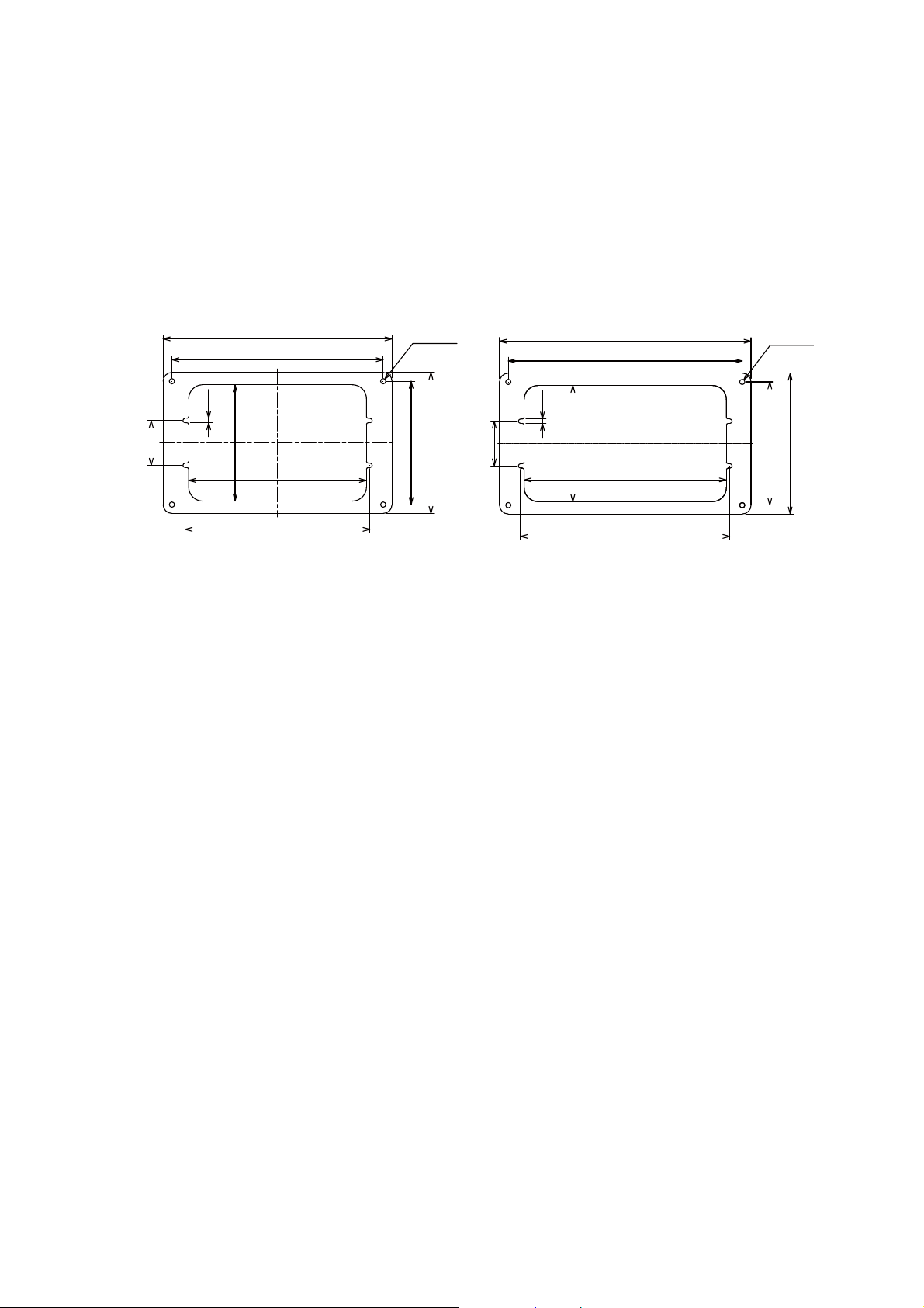
Follow the procedure below to mount the display unit in a console. Refer to the outline drawing at the back of this manual.
1. The thickness of the cutout should be 5 to 20 mm.
2. Prepare a cutout in the mounting location whose dimensions are shown in the
outline drawing at the back of this manual.
3. Screw in four threaded rods into the display unit.
4. Peel the paper from flush mount gasket and set the gasket to the display unit.
5. Set the display unit to the cutout and fasten it with the washers and nuts.
1-1
Page 4
1. MOUNTING
260
160
240
140
210
202
132
50.8
5
4-φ6
GP-1670/1670F Replacement Kit
GP-1870/1870F Replacement Kit
286
266
238
230
132
160
140
50.8
4-φ6
5
1.2 Replacement Kit (option)
For replace from the flush mounted former type display unit (GP-1650 ser.) to GP1670F/1870F, the replacement kit (option) is available. Follow the procedure below to
replace a display unit.
1. Remove the former display unit from panel.
2. Fix the display unit GP-1670F/1870F onto the repracement kit by four lods, washer and nuts.
3. Set the display unit to the cutout and fasten it with four tapping screws φ5×20.
1-2
Page 5
2. INSTALLATION OF TRANSDUC-
28
22
120
68
30
24
120
68
87
Unit: mm
520-5PSD
520-5MSD
BOW
ERS
2.1 How to Mount a Transducer through the Unit
Transducer mounting location
The thru-hull mount transducer provides the best performance of all, since the transducer protrudes from the hull and the effect of air bubbles and turbulence near the hull
skin is reduced. When the boat has a keel, the transducer should be at least 30 cm
away from it.
The performance of this fish finder is directly related to the mounting location of the transducer, especially for high-speed cruising. The
installation should be planned in advance,
keeping the length of the transducer cable and
the following factors in mind:
• Air bubbles and turbulence caused by movement of the boat seriously degrade the
sounding capability of the transducer. The
transducer should, therefore, be located in a
position where water flow is the smoothest.
Noise from the propellers also adversely affects performance and the transducer should
not be mounted nearby. The lifting strakes
are notorious for creating acoustic noise, and these must be avoided by keeping the
transducer inboard of them.
• The transducer must always remain submerged, even when the boat is rolling,
pitching or up on a plane at high speed.
• A practical choice would be somewhere between 1/3 and 1/2 of the boat's length
from the stern. For planing hulls, a practical location is generally rather far astern,
so that the transducer is always in water regardless of the planing attitude.
2-1
Page 6
2. INSTALLATION OF TRANSDUCERS
Within the wetted bottom area
Deadrise angle within 15°
Position 1/2 to 1/3 of the hull from stern.
15 to 30 cm off center line (inside first lifting
strakes.)
DEEP V
HULL
HIGH SPEED
V HULL
Hole for
stuffing tube
Saw along
slope of hull.
Upper Half
Lower Half
BOW
Transducer mounting locations
Installation procedure
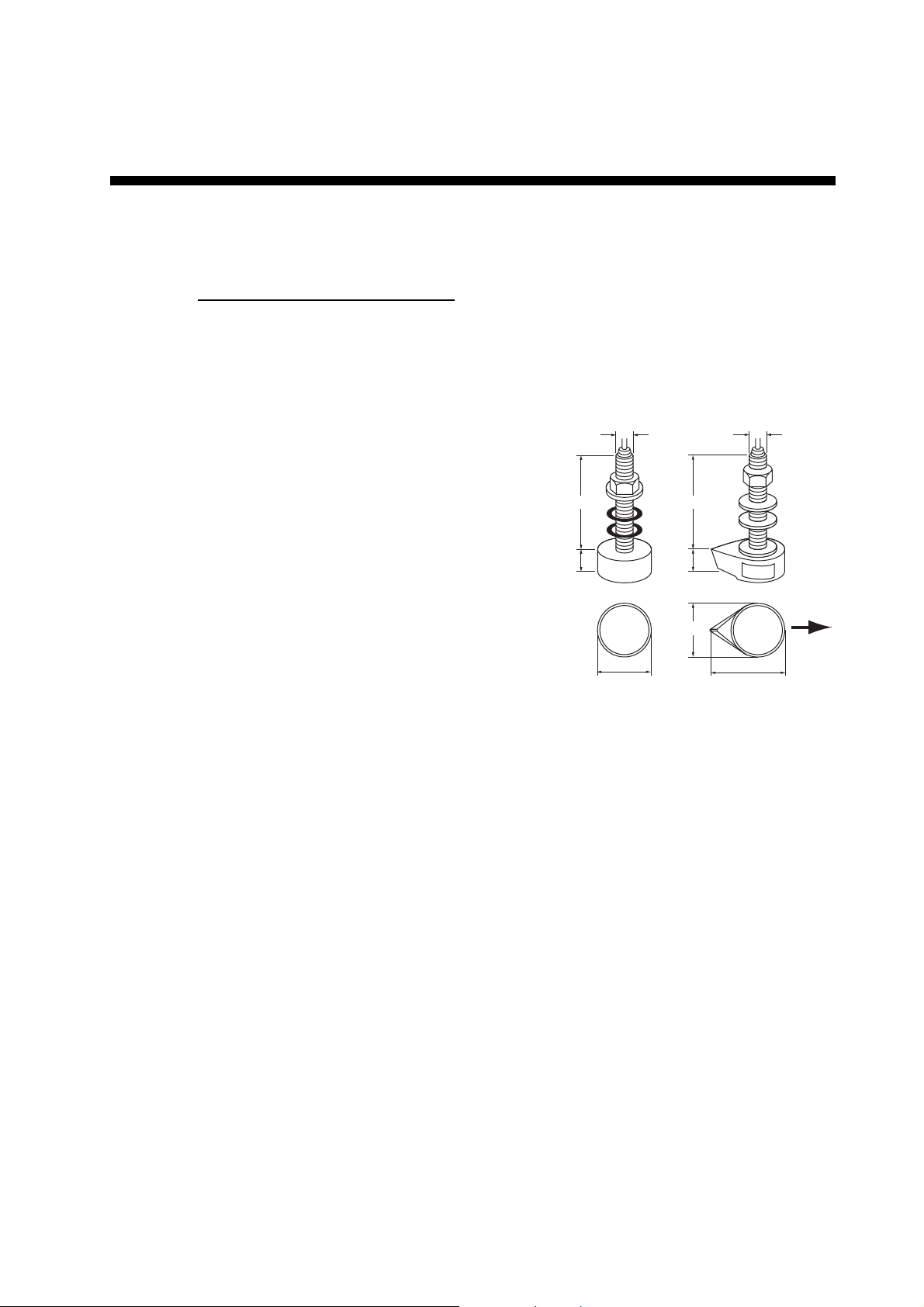
1. With the boat hauled out of the water, mark the location chosen for mounting the
transducer on the bottom of the hull.
2. If the hull is not level within 15° in any direction, fairing blocks made out of teak
should be used between the transducer and hull, both inside and outside, to keep
the transducer face parallel with the water line. Fabricate the fairing block as
shown below and make the entire surface as smooth as possible to provide an undisturbed flow of water around the transducer. The fairing block should be smaller
than the transducer itself to provide a channel to divert turbulent water around the
sides of the transducer rather than over its face.
3. Drill a hole just large enough to pass the threaded stuffing tube of the transducer
through the hull, making sure it is drilled vertically.
4. Apply a sufficient amount of high quality caulking compound to the top surface of
the transducer, around the threads of the stuffing tube and inside the mounting
2-2
hole (and fairing blocks if used) to ensure watertight mounting.
Page 7
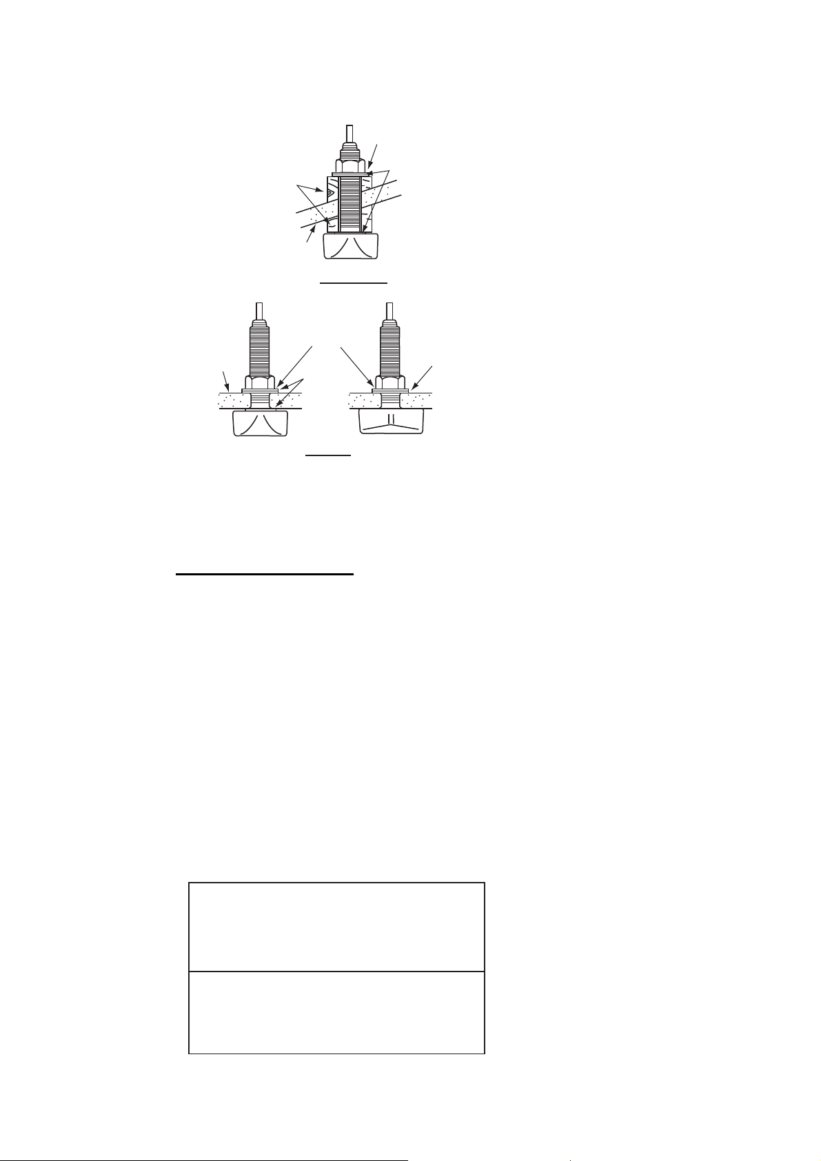
2. INSTALLATION OF TRANSDUCERS
5. Mount the transducer and fairing blocks and tighten the locknut. Be sure that the
transducer is properly oriented and its working face is parallel to the waterline.
Flat Washer
Fairing
Block
Hull
Deep-V Hull
Flat Washer
Hull
Rubber
Washer
Flat Hull
Rubber Washer
Cork
Washer
Note: Do not over-stress the stuffing tube and locknut through excessive tightening,
since the wood block will swell when the boat is placed in the water. It is suggested
that the nut be tightened lightly at installation and retightened several days after the
boat has been launched.
Transducer preparation
Before putting the boat in water, wipe the face of the transducer thoroughly with a detergent liquid soap. This will lessen the time necessary for the transducer to have good
contact with the water. Otherwise the time required for complete "saturation" will be
lengthened and performance will be reduced.
DO NOT paint the transducer. Performance will be affected.
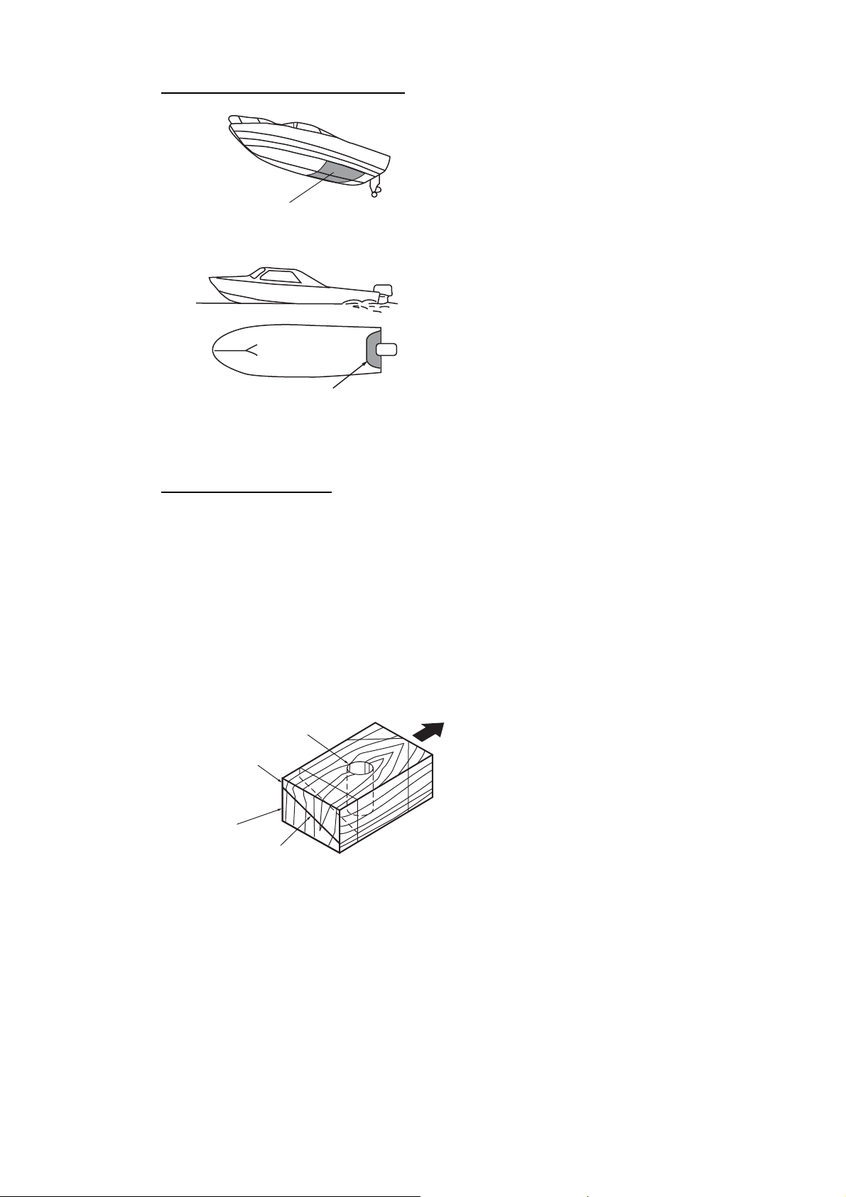
2.2 Transom Mount Transducer
The optional transom mount transducer is very commonly employed, usually on relatively small I/O or outboard boats. Do not use this method on an inboard motor boat
because turbulence is created by the propeller ahead of the transducer.
DO NOT overtighten screws; they may be damaged.
Parallel with hull
Transom
Less than 10°
Mount at the stripe.
Transom
Stripe
Over 10°
2-3
Page 8

2. INSTALLATION OF TRANSDUCERS
5x20
M5x14
5°
Taping
Bracket
Transducer
Hull
2 to 5°
Epoxy material
Installation procedure
A suitable mounting location is at least 50 cm away from the engine and where the
water flow is smooth.
1. Drill four pilot holes for self-tapping screw (5x20) in the mounting location.
2. Coat the threads of the self-tapping screws (5x14) for the transducer with silicone
sealant for waterproofing. Attach the transducer to the mounting location with the
self-tapping screws.
3. Adjust the transducer position so the transducer faces right to the bottom. If necessary, to improve water flow and minimize air bubbles staying on the transducer
face, incline the transducer about 5° at the rear. This may require a certain amount
of experimentation for fine tuning at high cruising speeds.
4. Tape the location shown in the figure below.
5. Fill the gap between the wedge front of
the transducer and transom with epoxy
material to eliminate any air spaces.
6. After the epoxy hardens, remove the
tape.
2.3 How to Mount a Transducer inside the Hull
The transducer may also be installed inside the hull on FRP boats. However, this installation method affects the ability to detect the bottom, fish and other objects because the ultrasound pulse is weakened when it passes through the hull.
Note: This mounting method should not be used to mount the transducer that sup-
TM
ports the ACCU-FISH
mance is greatly degraded.
Necessary tools
You will need the following tools:
and/or bottom discrimination display feature, since perfor-
2-4
• Sandpaper (#100)
• Silicone sealant
• Silicone grease
Page 9

2. INSTALLATION OF TRANSDUCERS
1/3
1/2
Centerline
Transducer
mounting
location
50 cm
50 cm
15 cm
15 cm
Transducer
Silicone
Sealant
Remarks on installation
• Do the installation with the ship moored at a dock, etc. The water depth should be 6.532 feet (2-10 meters).
• Turn off the engine.
• Install the transducer with the engine room.
• Do not power the unit with the transducer in the air, to prevent damage to the transducer.
• Do not use this method on a double layer hull.
• Before attaching the transducer to the hull, check that the site is suitable. Put the
transducer in a water-filled plastic bag. Connect the transducer to the display unit and
put the transducer on the installation site. Turn on the display unit and check that the
depth indication appears.
Installation procedure
If the thickness of the hull varies, then the attenuation of the ultrasound pulse. Select
a location where attenuation is the lowest.
1. Select 2-3 locations considering the four points mentioned below. (You will finalize
the mounting location through some trial and error later.)
• Mount the transducer at a location 1/2 to 1/3 of the length of the boat from the
stern.
• The mounting location is between 15 to 50 cm from the centerline of the hull.
• Do not place the transducer over hull struts or ribs which run under the hull.
• Avoid a location where the rising angle of the hull exceeds 15°, to minimize the
effect of the boat's rolling.
2. Clean the face of the transducer to remove any foreign material. Lightly roughen
the face with #100 sandpaper. Also, use the sandpaper to roughen the inside of
the hull where the transducer is to be mounted.
3. Wipe off any sandpaper dust from the face of the transducer.
4. Dry the face of the transducer and the hull.
Coat the transducer face and mounting location with silicone sealant. Hardening begins in
approx. 15-20 minutes so do this step without
delay.
2-5
Page 10

2. INSTALLATION OF TRANSDUCERS
5. Attach the transducer to the hull.
Press the transducer firmly down on the hull
and gently twist it back and forth to remove
any air which may be trapped in the silicone
sealant.
6. Support the transducer with a piece of wood
to keep it in place while the sealant is drying.
It takes 24-72 hours to harden completely.
Hull
Silicone
Sealant
2-6
Page 11

3. WIRING
Black
White
Shield
Display unit (back)
GPS antenna unit
GPA-017/017S (option)
CAN bus
equipment
Transducer
WARNING ELECTRICAL SHOCK
DO NOT touch the pins inside
connector. Put the cap (supplied) on
the connector when power is off or
the transducer is disconnected.
BATTERY
Cable connector
Power cable
w/fuse (3A)
Lead wire
White
Black
Shield
Ground
3.1 Display Unit
All wiring are terminated at the rear of the display unit. Refer to the interconnection
diagram on page S-1.
Power cable
Connect the power cable to the
power connector. Connect the
leads to the battery (12 or 24
VDC); white to plus(+) terminal
and black to minus(-) terminal.
Ground the shield to ship’s
ground.
Note: The fuse is not waterproof.
Wrap the fuse holder with vinyl
tape to keep water out of the fuse
holder.
3-1
Page 12

3. WIRING
Jumper block setting
J2: No output reduction (default)
J1: Output reduction
Transducer
50B-6/6B
50kHz
200kHz
SHIELD
BLK
RED
TB2
1
2
3
4
5
J2 J1
WHT
3
2
1
BLK
TB1
02P6348
BLK
RED
Connect 10P
connector to
XDR port on
rear of
display unit.
Green
(shield)
Detach grommet;
attach cord lock.
Transducer
200B-5S
Vinyl Sheath
Taping
Shrink Tubing
Shield
Crimp-on Lug
FV1.25-3 (LF)
3.2 Transducer
Connect the transducer cable to the XDR port.
Transducer and sensor
Use the optional conversion cable (02S4147) to connect the optional speed/temperature sensor and the transducer to the XDR port. Refer to Operator’s Manual in detail.
Matching box (option, required for 1 kW transducer)
The optional matching box (Type: MB-1100, Code No.: 000-041-353) is required to
connect the optional transducers 50B-6, 50B-6B, 200B-5S, 50/200-1T and 50/20012M.
Part Type Code no. Qty
Matching Box* MB-1100 000-041-000 1
Crimp-on Lug FV1.25-3 (LF) 000-116-756-10 6
Cord Lock** NC-1 000-168-230-10 1
*: With 10P connector cable
**: For connecting two transducers
3.3 External Equipment
About CAN bus connections
CAN bus is a communication protocol that shares multiple data and signals through a
single backbone cable. You can simply connect any CAN bus devices onto the backbone cable to expand your network onboard. With CAN bus, IDs are assigned to all
the devices in the network, and the status of each sensor in the network can be detected. All the CAN bus devices can be incorporated into the NMEA2000 network. For
detailed information about CAN bus wiring, see “Furuno CAN bus Network Design
Guide” (Type: TIE-00170) on Tech-Net), or contact your dealer.
3-2
Page 13

1
A-1
4
(*)
1
(*)
1
(*)
1
(*)
1
(*)
☆
1/1
14CW-X-9852 -1
NAME OUTLINE Q'TYDESCRIPTION/CODE №
000-176-666-10
MJ-A3SPF0013A-035C
999-999-179-00
VTATM4.8X22 TCC INX
999-999-187-00
C42-01201-*
999-999-190-00
GP-1X70 O/M *CD-ROM*
999-999-189-00
OS*-44770-*
999-999-192-00
IMC-44770-*
C4477‑Z01‑B
ケーブル(クミヒン)MJ
GP-1670F-E
CABLE ASSEMBLY
1
GP-1670F
タッピンネジ
(*)
図書 DOCUMENT
EXTERNAL BRACKET
FIXING SCREWS
1
999-999-194-00
0312 003.MXP
FLUSH MOUNTING TEMPLATE
フラッシュマウント型紙
(*)
999-999-186-00
2
OPERATOR'S MANUAL CD
取扱説明CD
(*)
999-999-197-00
VTSPKNOB-M6 FRN
OPERATOR'S GUIDE(E/J)
操作要領書(英/和)
1
(*)
999-999-184-00
HBS47A
INSTALLATION MANUAL
装備要領書
1
(*)
999-999-183-00
MINU CLOTH FRN
4
(*)
999-999-180-00
K10LC3005A
1
(*)
999-999-181-00
HGB10AX
型式/コード番号が2段の場合、下段より上段に代わる過渡期品であり、どちらかが入っています。 なお、品質は変わりません。
TWO TYPES AND CODES MAY BE LISTED FOR AN ITEM. THE LOWER PRODUCT MAY BE SHIPPED IN PLACE OF
THE UPPER PRODUCT. QUALITY IS THE SAME.
PACKING LIST
NAME OUTLINE Q'TYDESCRIPTION/CODE №
ユニット UNIT
GPSプロッタ/魚探
GPS PLOTTER/SOUNDER
予備品 SPARE PARTS
ヒューズ
付属品 ACCESSORIES
GLASS TUBE FUSE
ノブ
KNOB
ハンガー
EXTERNAL BRACKET
CLEANING CLOTH
フィルタークリーナー
工事材料 INSTALLATION MATERIALS
Fマウントネジキット
FLUSH MOUNT SCREWS KIT
FLUSH MOUNT GASKET
Fマウントパッキン
(*)は、ダミーコードに付き、注文できません。
(*) THIS CODE CANNOT BE ORDERED.
(略図の寸法は、参考値です。 DIMENSIONS IN DRAWING FOR REFERENCE ONLY.)
Page 14

1
A-2
4
(*)
1
(*)
1
(*)
1
(*)
1
(*)
☆
1/1
14CX-X-9852 -1
NAME OUTLINE Q'TYDESCRIPTION/CODE №
000-176-666-10
MJ-A3SPF0013A-035C
999-999-179-00
VTATM4.8X22 TCC INX
999-999-187-00
C42-01201-*
999-999-190-00
GP-1X70 O/M *CD-ROM*
999-999-189-00
OS*-44770-*
999-999-192-00
IMC-44770-*
C4479‑Z01‑B
ケーブル(クミヒン)MJ
GP-1870F-E
CABLE ASSEMBLY
1
GP-1870F
タッピンネジ
(*)
図書 DOCUMENT
EXTERNAL BRACKET
FIXING SCREWS
1
999-999-196-00
0312 003.MXP
FLUSH MOUNTING TEMPLATE
フラッシュマウント型紙
(*)
999-999-186-00
2
OPERATOR'S MANUAL CD
取扱説明CD
(*)
999-999-197-00
VTSPKNOB-M6 FRN
OPERATOR'S GUIDE(E/J)
操作要領書(英/和)
1
(*)
999-999-185-00
HBS48AX
INSTALLATION MANUAL
装備要領書
1
(*)
999-999-183-00
MINU CLOTH FRN
4
(*)
999-999-180-00
K10LC3005A
1
(*)
999-999-182-00
HGB11AX
型式/コード番号が2段の場合、下段より上段に代わる過渡期品であり、どちらかが入っています。 なお、品質は変わりません。
TWO TYPES AND CODES MAY BE LISTED FOR AN ITEM. THE LOWER PRODUCT MAY BE SHIPPED IN PLACE OF
THE UPPER PRODUCT. QUALITY IS THE SAME.
PACKING LIST
NAME OUTLINE Q'TYDESCRIPTION/CODE №
ユニット UNIT
GPSプロッタ/魚探
GPS PLOTTER/SOUNDER
予備品 SPARE PARTS
ヒューズ
付属品 ACCESSORIES
GLASS TUBE FUSE
ノブ
KNOB
ハンガー
EXTERNAL BRACKET
CLEANING CLOTH
フィルタークリーナー
工事材料 INSTALLATION MATERIALS
Fマウントネジキット
FLUSH MOUNT SCREWS KIT
FLUSH MOUNT GASKET
Fマウントパッキン
(*)は、ダミーコードに付き、注文できません。
(*) THIS CODE CANNOT BE ORDERED.
(略図の寸法は、参考値です。 DIMENSIONS IN DRAWING FOR REFERENCE ONLY.)
Page 15

1
A-3
(*)
1
4
(*)
1
(*)
1
(*)
1
(*)
1
(*)
☆
1/1
14CW-X-9854 -0
NAME OUTLINE Q'TYDESCRIPTION/CODE №
999-999-181-00
HGB10AX
000-176-666-10
MJ-A3SPF0013A-035C
999-999-179-00
VTATM4.8X22 TCC INX
999-999-187-00
C42-01201-*
999-999-190-00
GP-1X70 O/M *CD-ROM*
999-999-189-00
OS*-44770-*
999-999-192-00
IMC-44770-*
C4477‑Z02‑A
Fマウントパッキン
GP-1670F-J
FLUSH MOUNT GASKET
ケーブル(クミヒン)MJ
1
(*)
GP-1670F
CABLE ASSEMBLY
タッピンネジ
1
999-999-194-00
0312 003.MXP
図書 DOCUMENT
EXTERNAL BRACKET
FIXING SCREWS
(*)
999-999-186-00
1
FLUSH MOUNTING TEMPLATE
フラッシュマウント型紙
(*)
999-999-198-00
NEWPEC AND9**.**
OPERATOR'S MANUAL CD
取扱説明CD
2
(*)
999-999-197-00
VTSPKNOB-M6 FRN
OPERATOR'S GUIDE(E/J)
操作要領書(英/和)
1
(*)
999-999-184-00
HBS47A
INSTALLATION MANUAL
装備要領書
1
(*)
999-999-183-00
MINU CLOTH FRN
4
(*)
999-999-180-00
K10LC3005A
型式/コード番号が2段の場合、下段より上段に代わる過渡期品であり、どちらかが入っています。 なお、品質は変わりません。
TWO TYPES AND CODES MAY BE LISTED FOR AN ITEM. THE LOWER PRODUCT MAY BE SHIPPED IN PLACE OF
THE UPPER PRODUCT. QUALITY IS THE SAME.
PACKING LIST
NAME OUTLINE Q'TYDESCRIPTION/CODE №
ユニット UNIT
GPSプロッタ/魚探
GPS PLOTTER/SOUNDER
予備品 SPARE PARTS
ヒューズ
付属品 ACCESSORIES
GLASS TUBE FUSE
SDカード(NEWPEC)
NEWPEC JAPAN JHA-NP SD
CARD
ノブ
KNOB
ハンガー
EXTERNAL BRACKET
フィルタークリーナー
CLEANING CLOTH
工事材料 INSTALLATION MATERIALS
Fマウントネジキット
FLUSH MOUNT SCREWS KIT
(*)は、ダミーコードに付き、注文できません。
(*) THIS CODE CANNOT BE ORDERED.
(略図の寸法は、参考値です。 DIMENSIONS IN DRAWING FOR REFERENCE ONLY.)
Page 16

☆
A-4
1
1
4
(*)
1
(*)
1
(*)
1
(*)
1
(*)
1/1
14CX-X-9854 -0
NAME OUTLINE Q'TYDESCRIPTION/CODE №
999-999-182-00
HGB11AX
000-176-666-10
MJ-A3SPF0013A-035C
999-999-179-00
VTATM4.8X22 TCC INX
999-999-187-00
C42-01201-*
999-999-190-00
GP-1X70 O/M *CD-ROM*
999-999-189-00
OS*-44770-*
999-999-192-00
IMC-44770-*
C4479‑Z02‑A
Fマウントパッキン
GP-1870F-J
FLUSH MOUNT GASKET
ケーブル(クミヒン)MJ
1
(*)
GP-1870F
CABLE ASSEMBLY
タッピンネジ
1
999-999-196-00
0312 003.MXP
図書 DOCUMENT
EXTERNAL BRACKET
FIXING SCREWS
(*)
999-999-186-00
1
FLUSH MOUNTING TEMPLATE
フラッシュマウント型紙
(*)
999-999-198-00
NEWPEC AND9**.**
OPERATOR'S MANUAL CD
取扱説明CD
2
(*)
999-999-197-00
VTSPKNOB-M6 FRN
OPERATOR'S GUIDE(E/J)
操作要領書(英/和)
1
(*)
999-999-185-00
HBS48AX
INSTALLATION MANUAL
装備要領書
1
(*)
999-999-183-00
MINU CLOTH FRN
4
(*)
999-999-180-00
K10LC3005A
型式/コード番号が2段の場合、下段より上段に代わる過渡期品であり、どちらかが入っています。 なお、品質は変わりません。
TWO TYPES AND CODES MAY BE LISTED FOR AN ITEM. THE LOWER PRODUCT MAY BE SHIPPED IN PLACE OF
THE UPPER PRODUCT. QUALITY IS THE SAME.
PACKING LIST
NAME OUTLINE Q'TYDESCRIPTION/CODE №
ユニット UNIT
GPSプロッタ/魚探
GPS PLOTTER/SOUNDER
予備品 SPARE PARTS
ヒューズ
付属品 ACCESSORIES
GLASS TUBE FUSE
SDカード(NEWPEC)
NEWPEC JAPAN JHA-NP SD
CARD
ノブ
KNOB
ハンガー
EXTERNAL BRACKET
フィルタークリーナー
CLEANING CLOTH
工事材料 INSTALLATION MATERIALS
Fマウントネジキット
FLUSH MOUNT SCREWS KIT
(*)は、ダミーコードに付き、注文できません。
(*) THIS CODE CANNOT BE ORDERED.
(略図の寸法は、参考値です。 DIMENSIONS IN DRAWING FOR REFERENCE ONLY.)
Page 17

6/Apr/2012H.Maki
D-1
Page 18

6/Apr/2012H.Maki
D-2
Page 19

6/Apr/2012H.Maki
D-3
Page 20

6/Apr/2012H.Maki
D-4
Page 21

REDアカ
S-1
22/Mar/2012 Y.NISHIYAMA
351
24
MB-1100
10
XDR
XDR-M
10
XDR-SHIELD
43
XDR-P
TEMP0V
NC
TD_ID
TEMP
SPD0V/TDID0V/SHIELD
12V-P1
SPD
XDR
9
8
7
6
5
4
3
2
1
1m
MJ-A10SPF
*2
MB-1100
12345
02S4147,0.2m
クロ BLK
REDアカ
クロ BLK
REDアカ
ミドリ GRN
アオ BLU
クロ BLK
10
9
8
1
MJ-A10SRMD
6
5
4
3
2
1
MJ-A6SRMD
6
5
4
3
2
1
200B-5S
(1kW)
50B-6/6B50/200-1T
(1kW)
10m MJ-A10SPF
50/200-12M
GP-1670F/1870F
カラーGPSプロッタ魚探
相互結線図
GPS PLOTTER/SOUNDER
*2
525-5PWD
520-5PSD
520-5MSD
TRANSDUCER
送受波器
*2
ST-02MSB
ST-02PSB
TEMP/SPEED SENSOR
水温・船速センサー
または
OR
*2
T-02MSB
T-02MTB
T-03MSB
TEMP SENSOR
水温センサー
TITLE
T.YAMASAKI
名称
H.MAKI
INTERCONNECTION DIAGRAM
NAME
REF.No.
kg
XDR-M
10
9
XDR-SHIELD
8
XDR-P
7
TEMP0V
6
NC
5
TD_ID
4
TEMP
3
SPD0V/TDID0V/SHIELD
2
12V-P1
1
SPD
XDR
DISPLAY UNIT
指示部
GP-1670F/1870F
NET-S
NET-C
NET-H
GPS
J1
2
空中線部
ANTENNA UNIT空中線部
TNC-P-3
10m
GPA-017
1
GPA-017S
ANTENNA UNIT
USB
NJTP-3DXV
1m
N-J-3
N-P-8DFB
*2
30/50m
8D-FB-CV,
N-P-8DFB
1m
NJTP-3DXV
TNC-J-3
0.2m
USB2.0
4
A TYPE
USB CABLE
パソコン(保守用)
CAN bus
12345
M12-05PMMP
*2
PC (FOR MAINTENANCE)
ジャンクションボックス
SHIELD
NET-L
REDアカ
クロ BLK
シロ WHT
アオ BLU
M12-05BFFM,1/2/6m
*2
または OR
DATA CONVERTER
JUNCTION BOX
データ変換器
FI-5002
(+)
PWR
123
MJ-A3SPF
シロ WHT
3A
MJ-A3SPF0013-035,
*2
12-24VDC
IF-NMEA2K2
(-)
クロ BLK
3.5m
SHIELD
*1
100/110/
1
2
(+)
(-)
整流器
RECTIFIER
5
6
DPYC-1.5
220/230VAC
1φ,50/60Hz
MJ-A10SPF
*1
*2
PR-62
IV-2sq.
*2
8m,φ5.4
*2
10m,φ5.4
520-5PSD
525-5PWD
OR
または
525STID-MSD
525STID-PWD
520-5MSD
送受波器
送受波器
水温・船速センサー付
TRANSDUCER
TRANSDUCER
W/ TEMP/SPEED SENSOR
21/Mar/2012
21/Mar/2012
CHECKED
DRAWN
APPROVED
SCALE MASS
C4477-C01- A
DWG.No.
*2)オプション。
NOTE
*1: SHIPYARD SUPPLY.
*2: OPTION.
注記
*1)造船所手配。
A
B
C
 Loading...