

Page 1

INSTALLATION MANUAL
COLOR GPS/PLOTTER
GP-1650/1650D
Equipment Lists ......................................................i
System Configuration ............................................1
1. Installation of Standard Equipment ..................2
1.1 Installation of Display Unit .................................................2
1.2 Installation of Antenna Unit ................................................ 4
2. Wiring ..................................................................5
3. Initial Settings.....................................................8
3.1 NMEA Setting .....................................................................8
3.2 Output Data Sentences ...................................................... 10
3.3 Antenna Height.................................................................. 11
3.4 Baud Rate Setting (GP-1650D only)................................. 12
3.5 Beacon frequency Setting (GP-1650D only)..................... 13
4. Installation of DGPS Beacon Receiver
(for GP-1650).....................................................14
PACKING LIST .................................................... A-1
OUTLINE DRA WINGS......................................... D-1
INTERCONNECTION DIAGRAM ........................ S-1
SCHEMATIC DIAGRAM...................................... S-2
Page 2
9-52 Ashihara-cho,9-52 Ashihara-cho,
A
A
*00080856501**00080856501*
*00080856501**00080856501*
*IME43940M00**IME43940M00*
Nishinomiya, JapanNishinomiya, Japan
Telephone :Telephone : 0798-65-21110798-65-2111
Telefax :Telefax : 0798-65-42000798-65-4200
Your Local Agent/DealerYour Local Agent/Dealer
ll rights reserved.
ll rights reserved.
PUB.No.PUB.No. IME-43940-MIME-43940-M
(( TATATATA ))
GP-1650/1650DGP-1650/1650D
Printed in JapanPrinted in Japan
FIRST EDITION :FIRST EDITION : NOV.NOV. 19981998
M :M : FEB.FEB. 06,200206,2002
* 0 0 0 8 0 8 5 6 5 0 1 ** 0 0 0 8 0 8 5 6 5 0 1 *
*IME43940M00**IME43940M00*
* I M E 4 3 9 4 0 M 0 0 ** I M E 4 3 9 4 0 M 0 0 *
Page 3
SAFETY INSTRUCTIONS
Safety Instructions for the Installer
WARNING
Do not work inside the
equipment unless totally
familiar with electrical
circuits.
Hazardous voltage which can
shock, burn or cause serious
injury exists inside the equipment.
Turn off the power at the
mains switchboard before
beginning the installation.
Post a sign near the switch
to indicate it should not be
turned on while the equipment is being installed.
Fire, electrical shock or
serious injury can result if the
power is left on or is applied
while the equipment is being
installed.
Name: Warning Label (1)
Type: 86-003-1011-0
Code No.: 100-236-230
Page 4
Equipment Lists
Standard supply
.oNemaNepyT.oNedoCytQskrameR
1tinUyalpsiD
2tinUannetnA
3straPerapS10420-41PS036-473-400
4
5seirosseccA
noitallatsnI
slairetaM
0561-PG-
1
D0561-PG710-APG-10561-PGrof
810-APG- D0561-PGrof
910-APG- D0561-PGrof
1
00150-41PC084140-0001
10320-41PF038-573-4001revocdeaH
20320-41PF058-573-4001
Optional equipment
.oNemaNepyT.oNedoCskrameR
810-A01-0561-208-RG156-140-000.tnapihw,A0007-RG,810-APG
,regnahrofswercs
tnuomhsulfrofswercs
810-N01-0561-208-RG284-140-000A0007-RG,810-APG
810-A51-0561-208-RG256-140-000
1tiKrevieceRnocaeB
S810-N51-0561-208-RG384-140-000
910-N01-0561-208-RG056-140-000A0007-RG,910-APG
S910-N51-0561-208-RG356-140-000A0007-RG,S910-APG
2.yssaelbacannetnA51-D3-SP-CNT076-331-000
00710-02PC011-273-400
3teSelbacannetnA
01710-02PC021-273-400
4.yssAelbaC050-3000FPS7A-JM10-037-631-000
5erutxiftnuomtsaM1110-02PC087-563-400
6
esab
annetnaelgna-thgiR
033AQ-31.oN932-308-000
,A0007-RG,S810-APG
.tnapihw,51-D3-SP-CBT
,51-D3-SP-CNT,S810-APG
A0007-RG
elbacannetnarof,m51
noisnetxe
elbacannetnarof,m03
noisnetxe
elbacannetnarof,m05
noisnetxe
tinuannetnagnitnuomrof7esabannetnaelgna-L013AQ-31.oN042-308-000
8
esabannetnA
gnitnuomliarrof
0615CR-31.oN411-608-000
i
Page 5
Optional equipment (con't)
.oNemaNepyT.oNedoCskrameR
S810-APG264-140-000D0561-PGroF
9tinUannetnA
01
11reifitceR
21.yssAelbaC001-7000FPS6A-JM732-521-000S810/810-APGroF
31annetnApihW2.1-WAF640-031-000
41draCMAR400-CM20MAR00097-173-400BM2
nocaeBSPGD
revieceR
610-APG635-140-0000561-PGroF
S910-APG455-140-000D0561-PGroF
08-RG-0561-PGroF
26-RP
5#TN5.1/5YG5.2
26-RP
5#TN5.1/5YG5.2
26-RP
5#TN5.1/5YG5.2
26-RP
5#TN5.1/5YG5.2
484-310-000V001CA
584-310-000V011CA
684-310-000V022CA
784-310-000V032CA
ii
Page 6
GPA-017
(for GP-1650)
ANTENNA UNIT
Receives signal from
GPS satellite and beacon
reference station (GP-1650D
only).
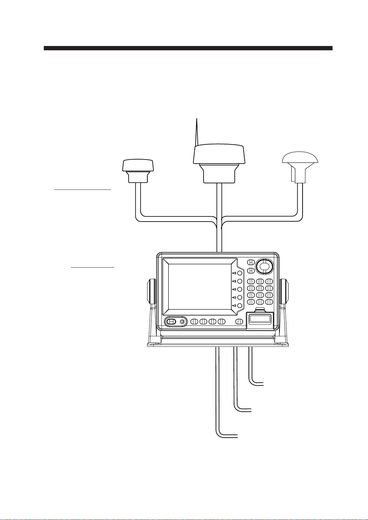
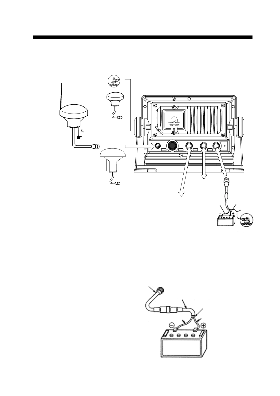
System Configuration
The GP-1650/1650D mainly consists of a display unit and a GPS
antenna. A DGPS beacon receiver is provided inside the display unit
for GP-1650D type. The chart card drive in the display unit loads
electronic charts. External equipment which may be connected include an autopilot and a DGPS beacon receiver.
GPA-018
(for GP-1650D)
GPA-019
(for GP-1650D)
DISPLAY UNIT
Ship’s position is
calculated in longitude
and latitude from signal
received from the antenna unit and displayed
on the screen.
Ship’s mains
10.8—31.2 VDC
External equipment
(Autopilot, etc.)
DGPS beacon receiver
GP-1650 only
1
Page 7
1. Installation of Standard Equipment
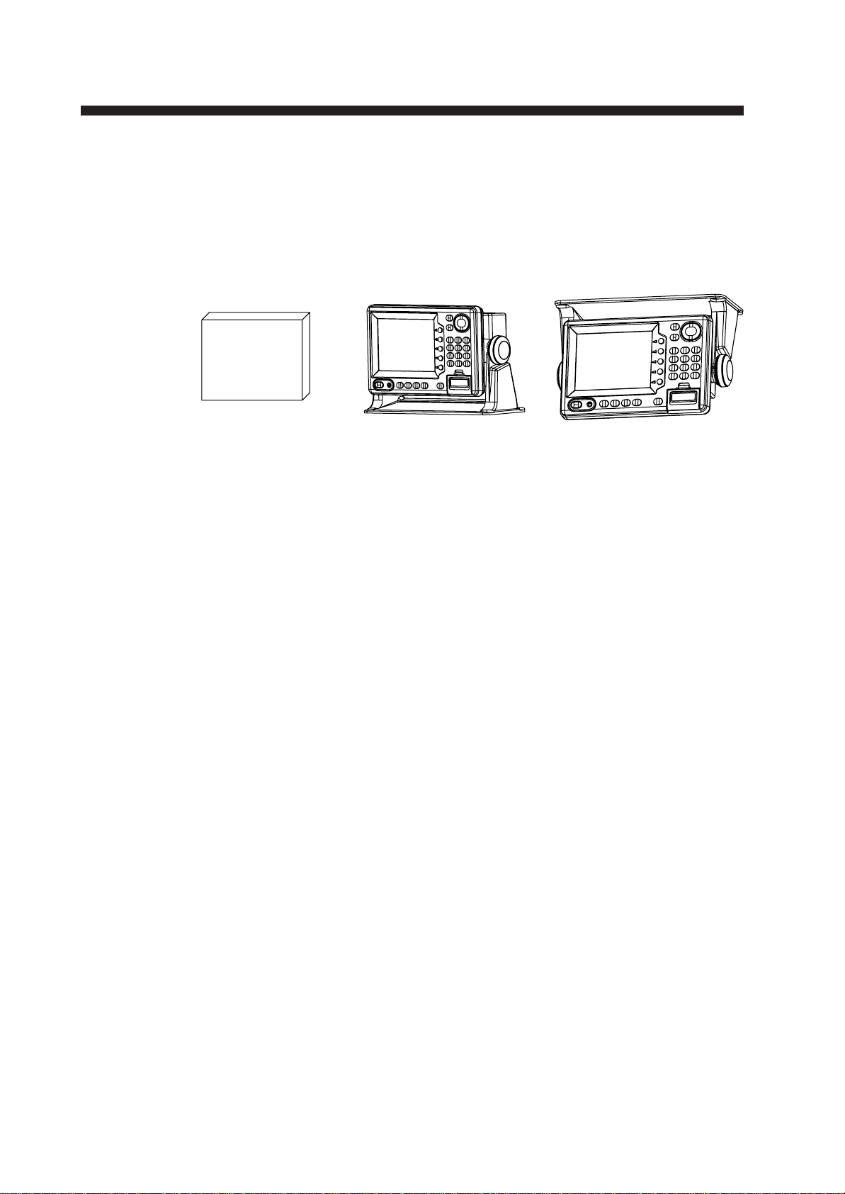
1.1 Installation of Display Unit
Mounting considerations
The display unit can be installed on a tabletop, on the overhead or
flush mounted in a console or panel.
Figure 1-1 Tabletop, overhead mounting methods
OverheadTabletopHard Cover
When selecting a mounting location for the display unit keep the following in mind:
• Keep the display unit out of direct sunlight.
• The temperature and humidity should be moderate and stable.
• Locate the unit away from exhaust pipes and vents.
• The mounting location should be well ventilated.
• Mount the unit where shock and vibration are minimal.
• Keep the unit away electromagnetic field generating equipment
such as motor, generator.
• For maintenance and checking purposes, leave sufficient space at
the sides and rear of the unit and leave slack in cables.
• A magnetic compass will be affected if placed too close to the
display unit. Observe the following compass safe distances to prevent disturbance to the magnetic compass:
Standard compass: 0.82 meters
Steering compass: 0.62 meters
2
Page 8
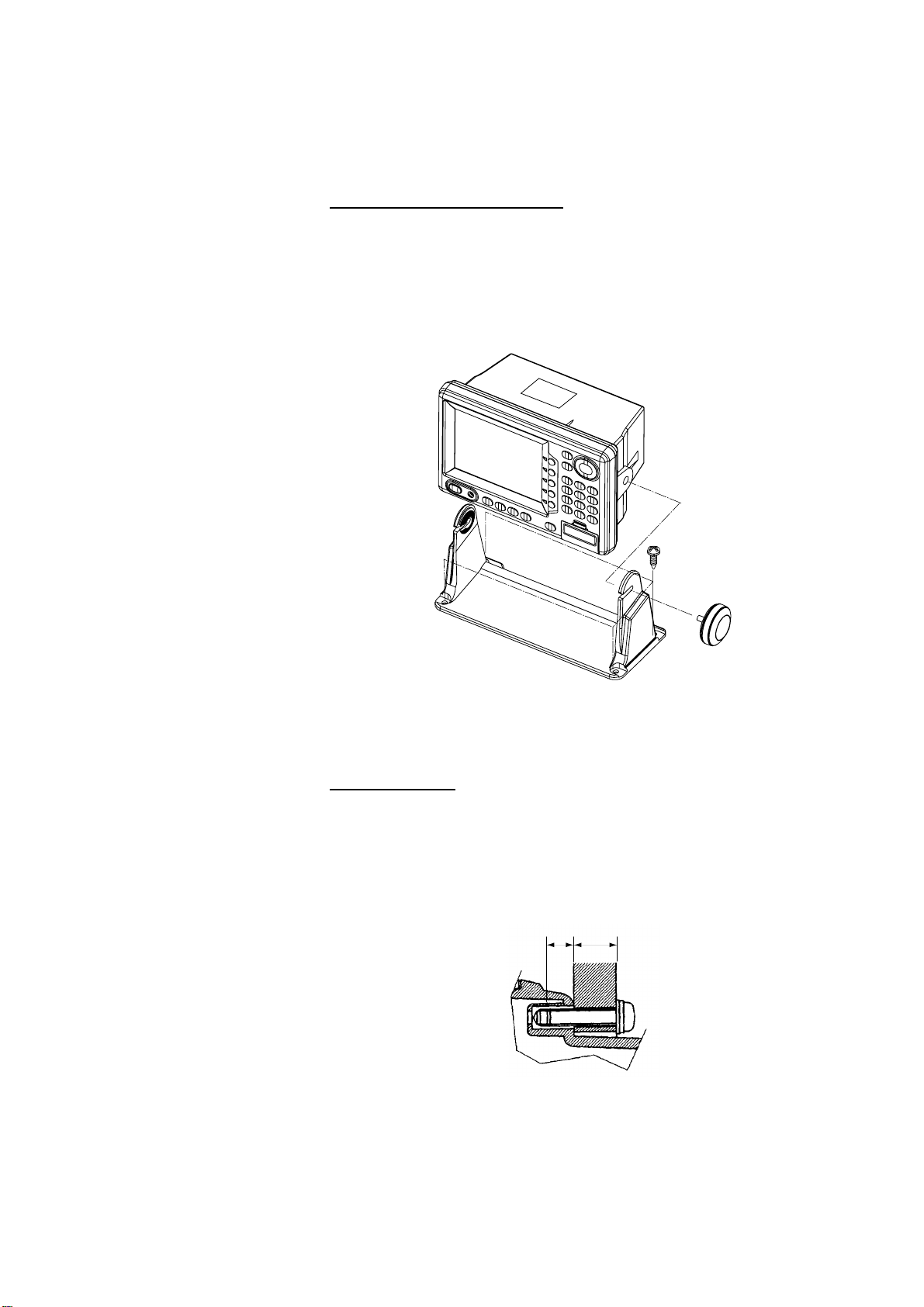
Mounting procedure
BA
Follow the procedure below to mount the display unit on a tabletop
or the overhead.
Tabletop, overhead mounting
1. Fix the hanger by four pan head screws M5 X 16.
2. Screw knob bolts in display unit, set it to hanger, and tighten
knob bolts.
3. Attach hard cover to protect LCD.
WARNING
Figure 1-2 Tabletop, overhead mounting of display unit
Flush mounting
Note: Use supplied pan head screws when the thickness of the bulkhead is from 11 to 14 mm. For bulkhead which exceeds 14 mm in
thickness the length of the pan head screws should be bulkhead thickness+7.8±1.5 mm. Also the length of B should max. 8mm.
1. Prepare a cutout in the mounting location whose dimensions are
as shown in Figure 1-3.
2. Fix the display unit by six pan head screws M4 X 20. Refer to the
outline drawing on page D-2.
3
Page 9
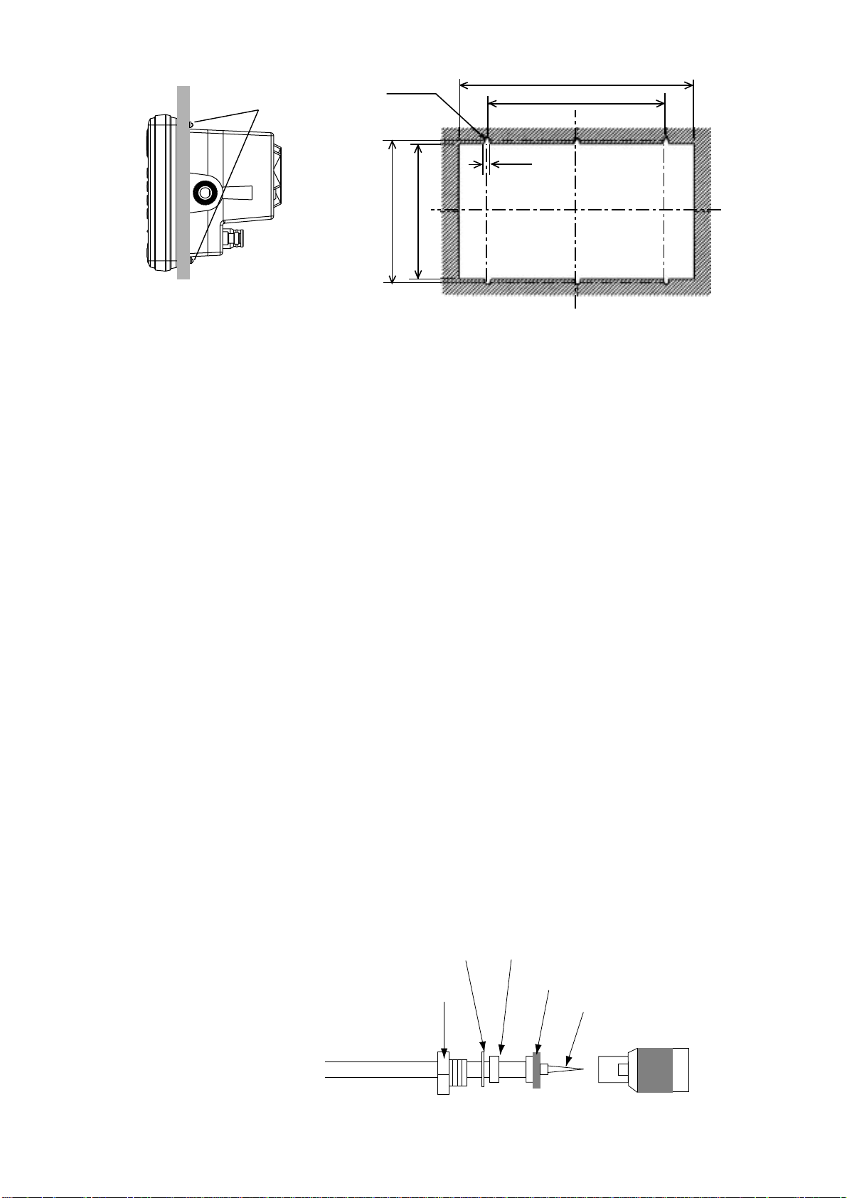
6-R2.25
Center pin (soldered)
Clamp nut
Connector shell
Gasket (reddish brown)Washer
Shield
Pan head screws
132±0.5
Flush mount
125±1
Figure 1-3 Flush mounting of display unit
1.2 Installation of Antenna Unit
Mounting considerations
Install the antenna unit referring to the installation diagram on page
D-3 or D-4. When selecting a mounting location for the antenna unit,
keep in mind the following points:
216±1
164±0.5
4.5
• Select a location out of the radar beam. The radar beam will obstruct or prevent reception of the GPS satellite signal.
• The location should be well away from a VHF antenna. A GPS
receiver is interfered by a harmonic wave of a VHF antenna.
• There should be no interfering object within the line-of-sight to
the satellites. Objects within line-of-sight to a satellite, for example,
a mast, may block reception or prolong acquisition time.
• Mount the antenna unit as high as possible. Mounting the antenna
unit as high as possible keeps it free of interfering objects and
water spray, which can interrupt reception of GPS satellite signal
if the water freezes.
• The length of the whip antenna for the GP-1650D should be no
longer than 1.2 meter to prevent antenna damage. Do not use a 2.5
meter whip antenna.
• Do not shorten the antenna cable.
• If the antenna cable is to be passed through a hole which is not
large enough to pass the connector , you may unfasten the connector with a needle nose pliers and 3/8-inch open-end wrench. Refasten it as shown in Figure 1-4 after running the cable through the
hole.
Figure 1-4 How to assemble the connector
4
Page 10
GPA-018
(GP-1650D)
Earth
terminal
ANTENNA UNIT
2. Wiring
All wiring are terminated at the rear of the display unit.
Earth terminal
DISPLAY UNIT
GPA-017
(GP-1650)
ANT
XDR
DGPS
NMEA
+
13GND
2
-
12-24
VDC
External
equipment
GPA-019
(GP-1650D)
DGPS beacon receiver
(option for GP-1650,
RS-232C only)
Black
White
Shield
Figure 2-1 Display unit, rear view
Power cable
Connect the power cable to the power connector. Connect the leads
to the battery (12 or 24 VDC); white to plus(+) terminal and black to
minus(-) terminal.
Cable connector
Power cable
w/fuse (3A)
Lead wire
Black
White
BATTERY
Figure 2-2 Connecting the power cable to the battery
5
Page 11
Antenna unit
Connect the antenna unit cable to the ANT connector.
Ground
The display unit contains several CPUs.
While they are operating, they radiate
noise, which can in-
CAUTION
Ground the equipment to
prevent electrical shock
and mutual interference.
terfere with radio
equipment. Ground
the unit to prevent interference. The grounding wire should be 1.25
sq or larger and as short as possible. Connect the grounding wire to
ship's ground. On a fiberglass boat, it is best to install a ground plate
that measures about 20 cm by 30 cm on the outside of the hull bottom
to provide a ground point. If this is not practical, the engine block can
be used.
Also, the antenna unit GPA-018S(option) type antenna units should
be grounded.
Note: Use a “closed” lug to make the ground connection at the dis-
play unit. Do not use an “open-type” lug ( ).
Extending antenna cable length
The standard cable is 10m long. For extension, in case of the GPA016, GPA-018or GPA-018S, an antenna cable set of 30m or 50m is
available. Extension cable cannot be used with the GPA-017 or GPA-
018.
◆ Extension cable line-up
Fabricate the end of the antenna cable and attach the coaxial con-
nector. Details are shown on next page.
Antenna Unit
GPA-016
GPA-018S
GPA-019S
1 m
Conversion
Cable Assy.
Antenna Cable
30 m or 50 m 1 m
Fabricate locally. (See next page.)
: Connector
To display unit
Figure 2-3 Cable extension
◆ Waterproofing connector
Wrap connector with vulcanizing tape and then vinyl tape. Bind
the tape end with cable-tie.
Figure 2-4 Waterproofing connector
6
Page 12
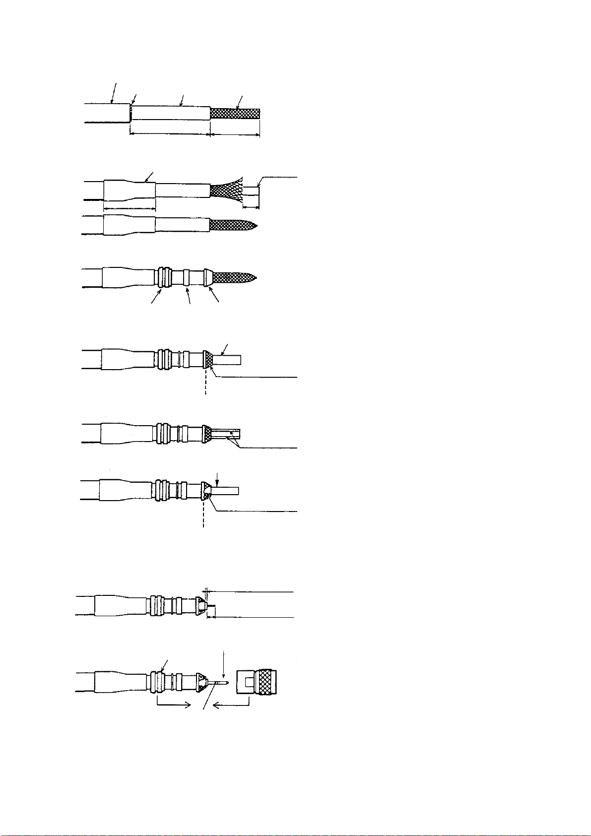
How to attach the N-P-8DFB connector
Outer Sheath
Cover with heat-shrink tubing and heat.
Armor
30
Clamp
Nut
Dimensions in millimeters.
Inner Sheath Shield
50
Gasket
(reddish
brown)
30
10
Clamp
Aluminum Foil
Remove outer sheath and armor by the dimensions
shown left.
Expose inner sheath and shield by the dimensions
shown left.
Cut off insulator and core by 10mm.
Twist shield end.
Ship on clamp nut, gasket and clamp as shown left.
Trim shield here.
Trim aluminum
tape foil here.
Clamp Nut
Insulator
1
5
Pin
Shell
Fold back shield over clamp and trim.
Cut aluminum foil at four places, 90° from one
another.
Fold back aluminum foil onto shield and trim.
Expose the insulator by 1mm.
Expose the core by 5mm.
Slip the pin onto the conductor. Solder them together
through the hole on the pin.
Insert the pin into the shell. Screw the clamp nut into
the shell.
Solder through
the hole.
(Tighten by turning the clamp nut. Do not tighten by
turning the shell.)
Figure 2-5 Fabrication of coaxial cable
7
Page 13

3.1 NMEA Setting
3. Initial Settings
NMEA port
1. Press the [MENU] key .
2. Press the software key labeled "CONFIGURATION".
3. Press the software key labeled "SETUP NMEA PORT1".
4. Select "FORMAT" by the arrow key.
5. Press the software key labeled "EDIT" to display the following
message.
s FORMAT NMEA 0183
OUTPUT FORMAT
VER 1.5
PORT1
▲
NMEA0183 Ver1.5
' NMEA0183 Ver2.0
▼
ENTER
SETUP
DGPS 3D
Figure 3-1 Output Format display
6. Select NMEA version by the arrow key. The selected item is indi-
cated by black button.
CANCEL
7. Press the software key labeled "ENTER".
8. Press the [PLOT] key to return to the plotter display.
8
Page 14

DGPS port
1. Press the [MENU] key.
2. Press the software key labeled "CONFIGURATION".
3. Press the software key labeled "SETUP NMEA/DGPS PORT2".
4. Select "FORMAT" by the arrow key.
5. Press the software key labeled "EDIT" to display the following
message.
s FORMAT NMEA 0183
DGPS 3D
OUTPUT FORMAT
▲
NMEA0183 Ver1.5
' NMEA0183 Ver2.0
RTCM104 (EXTRN)
RTCM104 (INTRN)
RTCM104 (OUTPUT)
▼
VER 1.5
▲▲▲
SETUP
PORT2
ENTER
CANCEL
Figure 3-2 Output Format Display
6. Select NMEA version, external DGPS or internal DGPS by the
arrow key. The selected item is indicated by black button.
NMEA0183Ver1.5/Ver2.0 :Select one when connecting PC
or RS-232C equipment.
RTCM104(EXTRN) :Select this when connecting
external DGPS beacon receiver .
RTCM104(INTRN) :Select this for builtin internal
DGPS beacon receiver.
RTCM104(OUTPUT) :Select this when outputting
deifferential data of the internal
DGPS beacon receiver to other
GPS navigator.
Note 1) Note that you cannot setup sentences when you select
RTCM104 at the format.
Note 2) For RS-422 format, the level converter (IF-1432) is
required for connection of external equipmemt.
7. Press the software key labeled "ENTER".
8. Press the [PLOT] key to return to finish.
9
Page 15

3.2 Output Data Sentences
Select output data sentences for external equipment as follows:.
1. Press the [MENU] key.
2. Press the software key labeled "CONFIGURATION".
3. Press the software key labeled "SETUP NMEA PORT1".
4. Press the software key labeled "SELECT SNTNC." to display
the following list.
SELECT
SNTNC.
ON/OFF
s
SELECT SENTENCE
sAAM
APB ON
BOD
BWR
GGA
GLL
MTW ON
RMA
RMB ON
RMC ON
VTG ON
WPL
XTE
ZDA ON
DGPS 3D
RETURN
Figure 3-3 Output Data Sentences Display
5. Select data sentence you want to output by the arrow key.
6. Press the software key labeled "ON/OFF". To output data, set to
"ON".
7. Repeat to select other sentences.
8. Press the software key labeled "RETURN".
9. Press the [PLOT] key to return the plotter display.
Input/Output data sentences
troPtamroFataDskrameR
tupnI
AEMN
tuptuO
tupnI
SPGD
tuptuO
-AEMN•
3810
0.2.reV
5.1.reV
2611CEI•
2*DTG
-AEMN•
3810
0.2.reV
5.1.reV
C232SR•
401MCTR•
2*DTG
.ylevitucesnoctupniebtonnaC:1*
.detcelessiALroCLnehwyllacitamotuatuptuO:2*
TPD/TBD,1*LPW,MWD,1*LLT
,RWB/CWB,DOB,BPA,MAA
,CMR,BMR,AMR,LLG,AGG
,WTM,ADZ,ETX,LPW,GTV
TPD/TBD,1*LPW,WTM,1*LLT
,RWB/CWB,DOB,BPA,MAA
,CMR,BMR,AMR,LLG,AGG
,WTM,ADZ,ETX,LPW,GTV
10
ylnoPG:LPW
TBD:5.1reVAEMN
TPD:0.2reVAEMN
CWB:ELCRICTAERG
RWB:ENILBMUHR
ylnoPG:LPW
TBD:5.1reVAEMN
TPD:0.2reVAEMN
CWB:ELCRICTAERG
RWB:ENILBMUHR
Page 16

3.3 Antenna Height
1. Press the [MENU] key.
2. Press the software key labeled "GPS/DGPS/TD OPTIONS".
3. Press the software key labeled "GPS SETUP OPTIONS".
4. Select "ANT. HEIGHT" by the arrow key.
5. Press the software key labeled "EDIT".
6. Enter the height (3 digits) of the antenna above sea level using
ANT. HEIGHT
0 0 5 m
Figure 3-4 Antenna Height Display
the numeric keys.
If you enter wrong antenna height, press the software key
labeled "CLEAR".
7. Press the [ENTER] key.
8. Press the [PLOT] key to return the plotter display.
11
Page 17

3.4 Baud Rate Setting (GP-1650D only)
1. Press the [MENU] key .
2. Press the software key labeled "GPS/DGPS/TD OPTIONS".
3. Press the software key labeled "DGPS SETUP OPTIONS" to display the following message.
s FORMAT NMEA 0183
DGPS MODE ON
BEACON FREQUENCY AUTO
s
BEACON BAUD RATE AUTO
DGPS ALARM OFF
DGPS
OPTION
VER 1.5
EDIT
DGPS 3D
Figure 3-5 DGPS Setup Options Display
4. Confirm that "ON" is selected at "DGPS MODE" field for
GP-1650D.
5. Select "BEACON BAUD RATE" by the arrow key.
6. Press the software key labeled "EDIT" to display the following
message. Beacon baud rate cannot be set when "BEACON
FREQUENTRY" is set to "AUTO".
RETURN
BEACON BAUD RATE
▲
200
' 100
50
▼
Figure 3-6 Beacon Baud Rate Display
7. Select beacon baud rate corresponding to DGPS reference station to use.
8. Press the [ENTER] key.
9. Press the [PLOT] key to return the plotter display.
12
Page 18

3.5 Beacon frequency Setting (GP-1650D only)
1. Press the [MENU] key.
2. Press the software key labeled "GPS/DGPS/TD OPTIONS".
3. Press the software key labeled "DGPS SETUP OPTIONS" to display the following message.
s FORMAT NMEA 0183
DGPS MODE ON
BEACON FREQUENCY AUTO
s
BEACON BAUD RATE AUTO
DGPS ALARM OFF
VER 1.5
DGPS
OPTION
EDIT
DGPS 3D
Figure 3-7 DGPS Setup Options Display
4. Select "BEACON FREQUENCY" by the arrow key.
5. Press the software key labeled "EDIT" to display the following
message.
RETURN
BEACON FREQUENCY
▲
' AUTO
MANUAL s 284.0 kHz
▼
Figure 3-8 Beacon Frequency Display
6. Select "AUTO" or "MANUAL" by the arrow key. When you select "MANUAL", operate the cursor pad to move the cursor to
frequency dialog box. And press the arrow key to select the frequency desired.
7. Press the [ENTER] key.
8. Press the [PLOT] key to return to finish.
13
Page 19

4. Installation of DGPS Beacon Receiver (for GP-1650)
The DGPS beacon receiver GR-7000A can be incorporated in the
GP-1650 to provide it with DGPS capability . Six installation kits are
available as shown.
GR-802-1650-10A-018 GR-802-1650-15A-018S
GR-802-1650-10N-018 (No whip ant.) GR-802-1650-15N-018S (No whip ant.)
emaNepyT.oNedoCytQ
tinUannetnAS810-APG264-140-0001
nocaeB
revieceR
.yssAelbaC51-D3-SP-CNT076-331-0001
rotcennoC
.yssA
daehnaP
swercs
eitelbaC001-VC223-075-0002
*wercS403SUS21X3M509-508-0006
.yssAelbaC
annetnapihW
)ylnoepytA51(
pmalCN2-PH000-075-0001
*.yssAelbaC
*wercS014SUS8X3159-208-0004
desutoN*
A0007-RG942-341-0001
042L-W-P6HP845-141-0001
W0072C01X3M504-188-0004
-D-7.0PL2-2LF.S
)121(THW
2.1-WAF640-031-0001
-D-7.0PL2-2LF.S
)052(THW
194-141-0001
778-341-0001
GR-802-1650-10N-019 (No whip ant.) GR-802-1650-15N-019S (No whip ant.)
emaNepyT.oNedoCytQ
tinUannetnA910-APG255-140-0001
nocaeB
revieceR
rotcennoC
.yssA
daehnaP
swercs
eitelbaC001-VC223-075-0002
*wercS403SUS21X3M509-508-0006
.yssAelbaC
pmalCN2-PH000-075-0001
*.yssAelbaC
*wercS014SUS8X3159-208-0004
desutoN*
A0007-RG942-341-0001
042L-W-P6HP845-141-0001
W0072C01X3M504-188-0004
-D-7.0PL2-2LF.S
)121(THW
194-141-0001
-D-7.0PL2-2LF.S
)052(THW
778-341-0001
emaNepyT.oNedoCytQ
tinUannetnAS910-APG455-140-0001
nocaeB
revieceR
.yssAelbaC51-D3-SP-CNT076-331-0001
rotcennoC
.yssA
daehnaP
swercs
eitelbaC001-VC223-075-0002
*wercS403SUS21X3M509-508-0006
.yssAelbaC
pmalCN2-PH000-075-0001
*.yssAelbaC
*wercS014SUS8X3159-208-0004
desutoN*
A0007-RG942-341-0001
042L-W-P6HP845-141-0001
W0072C01X3M504-188-0004
-D-7.0PL2-2LF.S
)121(THW
-D-7.0PL2-2LF.S
)052(THW
194-141-0001
778-341-0001
14
Page 20

Disassembly
Procedure
1. Turn off the power. Wait at least one minute before opening
the cover, to allow capacitors to discharge.
2. Remove nuts attached to DGPS, NMEA and power supply
connectors at the rear of the display unit.
Nut, Washer
WARNING
Do not connect the power
cable with the cover
removed.
Nut
COVER ASSEMBLY
Screws X 6 B
Screws X 6 A
PANEL/CHASSIS ASSEMBLY
Connector gasket
Figure 4-1 Removing cover assembly
3. Remove nuts and washer attached to ANT connector.
4. Remove twelve screws at rear of the display unit to detach
panel/chassis assembly from cover assembly.
Discard six screws A (3X12).
15
Page 21

A
View
Installation of DGPS receiver
Procedure
1. Disconnect 8P connector as shown in the figure below.
CHASSIS ASSEMBLY
A
CONNECTOR
PH8P
J106
(P) MAIN
PANEL ASSEMBLY
Figure 4-2 Dismounting chassis assembly
2. Dismount chassis assembly from panel assembly by disconnecting connector shown in the figure above.
3. Cut the cable ties as shown in the figure below.
ANLG board
J8
Cut cable tie.
Cut cable tie.
GN-7707
Figure 4-3 Cutting cable ties
4. Dismount heat sink from chassis assembly by unfastening four
screws on the ANLG board and disconnecting the connector of
the mini pin coaxial cable.
Handling of Coaxial Cable
• Do not touch the connector with bare hands;
use gloves.
• Use radio pincers to remove, and pull out
straightly.
• Plug in connector straightly.
16
Page 22

Screws X 4
ANLG Board
Mini pin connector
GN-7707
A
Mini pin coax. cable
Heat sink
Figure 4-4 Chassis assembly
5. Take off the mini pin coxial cable from J2 on the GN-7707.
6. Open the lid of GR-7000A.
7. Connect the mini pin coxial cable to J1 of GR-7000A.
J1
Mini pin coax. cable
Cable assy.
S.FL2-2LP0.7-D-WHT (121)
J3
Notch
Beacon receiver
GR-7000A
Figure 4-5 Beacon receiver
8. Connect cable assy. S.FL2-2LP0.7-D-WHT (121) (supplied) to
J3 of the GR-7000A.
9. Close the lid of the GR-7000A.
10. Connect connector assy. PH6P-W-L240 to J2 of GR-7000A (Refer to Figure 4-6).
11. Fasten the GR-7000A (Beacon receiver) to the heat sink with four
M3X10 screws (supplied) as shown in the figure below.
17
Page 23

Pan-head Screw B
M3X10, 4 pcs.
Connect to
J8 on ANLG
Board.
S.FL2-2LPO.7-D-WHT (121)
Connect to
J2 on GN-7707.
Connect to
J106 on
MAIN Board.
GN-7707
Connect to J107
on MAIN Board
J2
Beacon Receiver Board
GR-7000A
HEAT SINK
Figure 4-6 Installation of DGPS beacon receiver
Cable Assy.
PH6P-W-L240
Cover of GR-7000A
Notch
12. Connect the cable assy . S.FL2-2LP0.7-D-WHT (121) of J3 to J2
of the GN-7707.
13. Pass the mini pin coaxial cable of J1 on the GR-7000A through
the mini plug on the ANLG Board and connect it to J8 on the
ANLG Board.
14. Mount the ANLG board on the heat sink.
GR-7000A
Mini pin coxial cable
GN-7707
HEAT SINK
Connect cable assy.
J1 of GN-7707 to J106
of MAIN board.
to J8 of
ANLG board
to J106 of
MAIN board
Clamp
J1
GN-7707
J2
GR-7000A
J1
Cable tie
Connect mini pin coaxial cable
between J1 of GR-7000A and J8 of
ANLG board.
J2
Connect cable assy.
J3
J3 of GR-7000A to
J2 of GN-7707.
to J107 of
MAIN board
Connect PH6P-W-L240 between J2 of
GR-7000A and J107 of MAIN board.
Figure 4-7 Wiring the Cable assembly
18
Page 24

15. Mount chassis assembly on the panel assembly. Connect 8P con-
m
nector and 6P connector to Main board as shown in the figure
below.
CHASSIS ASSEMBLY
A
Connector
View
A
PH8P
J106
(P) MAIN
PH6P
J107
PANEL ASSEMBLY
Figure 4-8 Attaching chassis assembly
16. Fasten 8P connector cable and 6P connector cable by cable tie as
shown in the figure below . Fasten mini pin coaxial cable by cable
tie as shown in the figure.
Note: After connecting, pull up cable to remove slack so
Cable tie
as not to pinch the cable between cover panel assembly.
ANLG board
PH8P
MAIN Board
J106
Mini pin coax. cable
PH6P
J107
J8
Cable tie
Figure 4-9 Attaching cable tie
17. Reassemble the display unit.
Use new screws size 3X12 (supplied).
Nut, Washer
Torque:
1.37~1.57 N
m
Nut
Torque: 0.74~0.78 N m
COVER ASSEMBLY
Screws X 6
Torque:
0.74~0.78 N
New screws X 6
Torque:
0.74~0.78 N
m
Figure 4-10 Remounting the cover
Note: When reattaching the cover, confirm the following parts are
attached.
.
.
Shield gasket, cover gasket (See figure 4-11.)
Connector gasket (See figure 4-1.)
19
Page 25

Cover gasket
Shield gasket(1)
Shield gasket (2)
Figure 4-11 Gaskets
Checking the DGPS installation
1. Press the [MENU] key .
2. Press the software key labeled "CONFIGURATION".
3. Press the software key labeled "SYSTEM MENU".
4. Press the software key labeled "SELF TEST".
5. Press the software key labeled "MEMORY•I/O TEST" to display
the following message.
TEST
PRPGRAM:OK
NO.14518010XX
SRAM:OK
DRAM:OK
PORT1:OK*
PORT2:OK*
INTERNAL
BATTERY: OK
GPS
RECEIVER:OK
NO.48502060XX
BEACON
RECEIVER:OK
NO.0850182-0XX
NO.
RETURN
*Special connections are required to check these ports.
Otherwise, NG appears.
Figure 4-12 Memory, I/O Test Display
6. Confirm that "BEACON RECEIVER: OK" is displayed.
7. Press the software key labeled "RETURN".
8. Press the [PLOT] key to return the plotter display.
20
Page 26

Connecting DGPS beacon receiver
A DGPS beacon receiver whose output format is RS-232C can be
connected to the GP-1650.
Below is the example of interconnection between the GP-1650 and
FURUNO beacon receiver GR-80.
GP-1650
DGPS
RD
SD
SG
1
2
3
4
5
6
7
Can use MJ-A7SPF0003-050
(OPTION).
YELLOW
RED
BLUE
Figure 4-13 Connecting DGPS beacon receiver
GR-80
(setting RS-232C)
1
3
7
DATA
TD-B
RD-B
GND
21
Page 27

Page 28

Page 29

Page 30

Page 31

Page 32

Page 33

Page 34

Page 35

Page 36

Page 37

Page 38

Page 39

 Loading...