

Page 1
Back
Page 2

9-52 Ashihara-cho,9-52 Ashihara-cho,
x
A
A
*00080637800**00080637800*
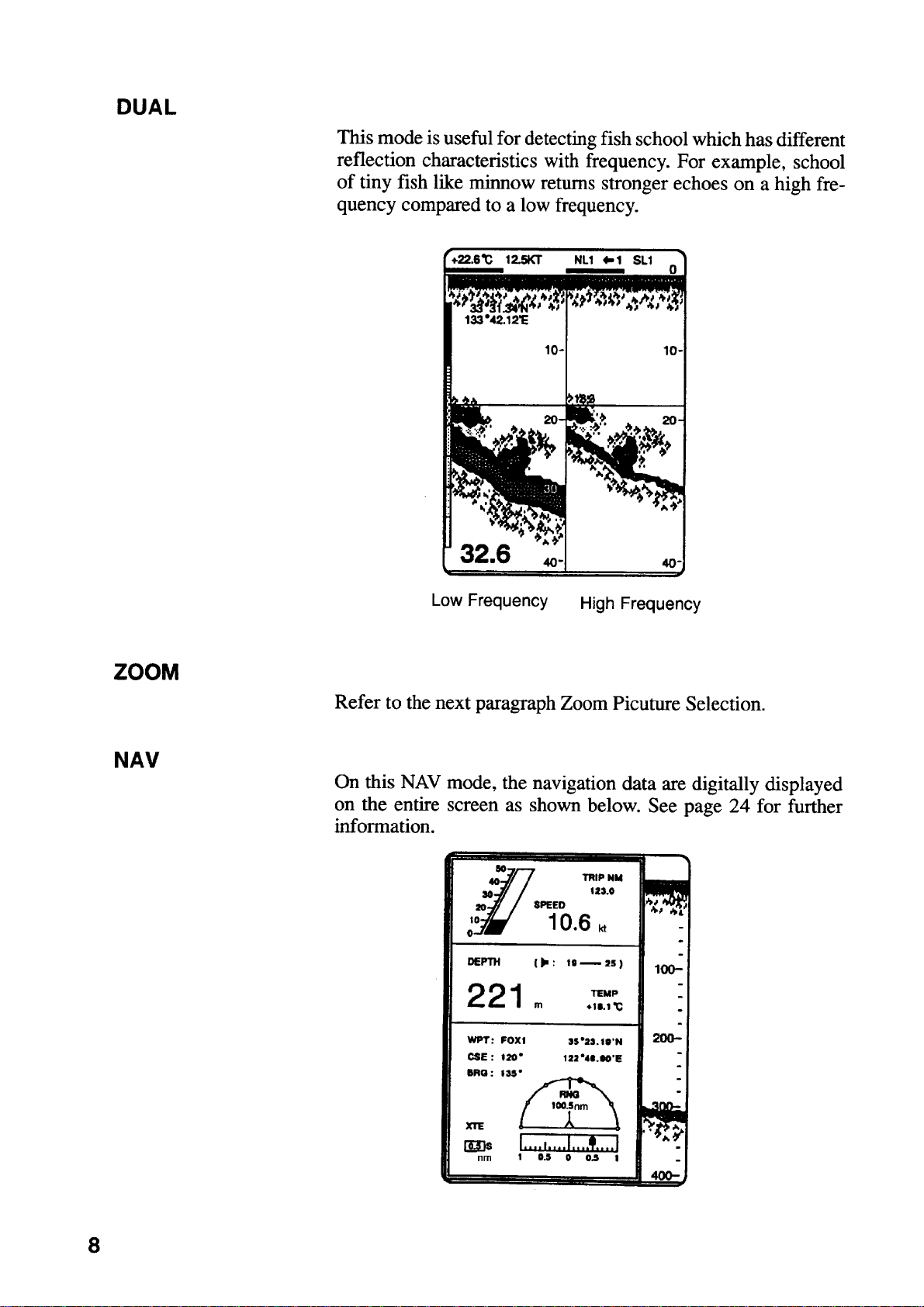
*00080637800**00080637800*
*OME23520L10**OME23520L10*
Nishinomiya, JapanNishinomiya, Japan
Telephone :Telephone : 0798-65-21110798-65-2111
faxfa
ll rights reserved.
ll rights reserved.
PUB.No.PUB.No. OME-23520OME-23520
0798-65-42000798-65-4200
::
Printed in JapanPrinted in Japan
Your Local Agent/DealerYour Local Agent/Dealer
IRST EDITION :
IRST EDITION : OCT.OCT. 19941994
L1L1 :: DEC.DEC. 24,200324,2003
(( TENITENI ))
FCV-292FCV-292
* 0 0 0 8 0 6 3 7 8 0 0 ** 0 0 0 8 0 6 3 7 8 0 0 *
*OME23520L10**OME23520L10*
* O M E 2 3 5 2 0 L 1 0 ** O M E 2 3 5 2 0 L 1 0 *
Page 3
Page 4
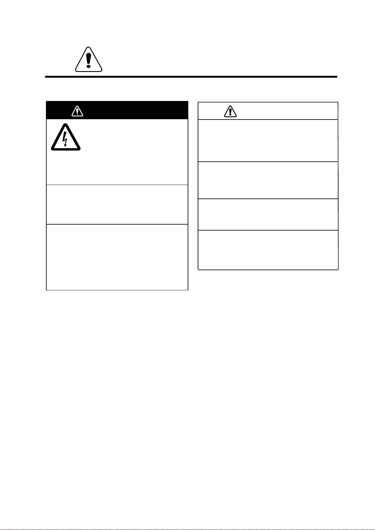
SAFETY INFORMATION
FOR THE OPERATOR
WARNING
Do not open the cover of
the equipment.
This equipment uses high voltage
electricity which can shock, burn,
or cause death.
Only qualified personnel should
work inside the equipment.
Do not dissasemble or modify the
equipment.
Fire, electrical shock or serious injury can result.
Immediately turn off the power at the
ship's mains switchboard if water or
foreign object falls into the equipment
or the equipment is emitting smoke or
fire.
Continued use of the equipment can cause fire,
electrical shock or serious injury.
CAUTION
Do not place liquid-filled containers
on the top of the equipment.
Fire or electrical shock can result if a liquid
spills into the equipment.
Do not place heater near the equipment.
Heat can melt the power cord, which can
result in fire or electrical shock.
Do not operate the unit with wet hands.
Electrical shock can result.
Use the correct fuse.
Use of the wrong fuse can cause fire or
equipment damage.
(Continued on next page)
ii
Page 5

Page 6
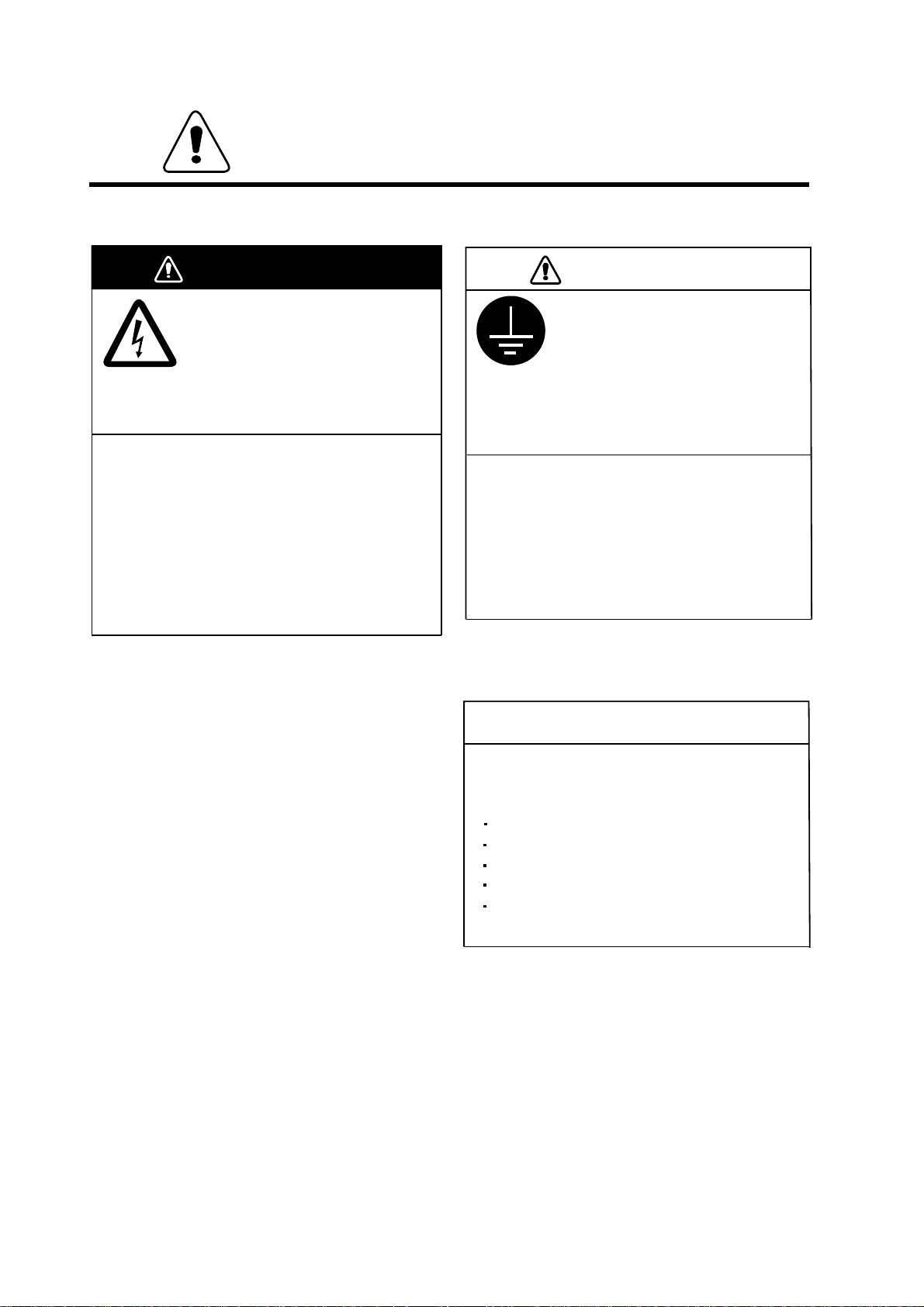
SAFETY INFORMATION
FOR THE INSTALLER
WARNING
Only qualified personnel
should work inside the
equipment.
This equipment uses high voltage
electricity which can shock, burn,
or cause death.
Turn off the power at the ship's mains
switchboard before beginning the
installation. Post a warning sign near
the switchboard to ensure that the
power will not be applied while the
equipment is being installed.
Serious injury or death can result if the power is
not turned off, or is applied while the equipment
is being installed.
CAUTION
Ground the equipment to
prevent electrical shock and
mutual interference.
Ungrounded equipment can give
off or receive electro-magnetic
interference or cause electrical
shock.
Confirm that the power supply voltage
is compatible with the voltage rating
of the equipment.
Connection to the wrong power supply can
cause fire or equipment damage. The voltage
rating appears on the label at the rear of the
equipment.
NOTICE
The mounting location must satisfy the
following conditions:
Away from rain and water splash
Out of direct sunlight
Away from air conditioner vents
Away from magnets and magnetic fields
Moderate and stable in temperature and
humidity
iv
Page 7
Page 8
Page 9

Table of Contents
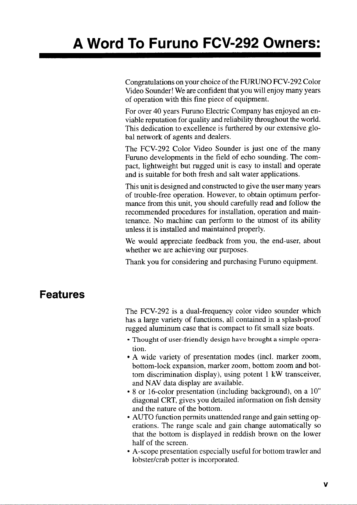
A Word To Furuno FCV-292 Owners:..................................................................i
Features................................................................................................................................i
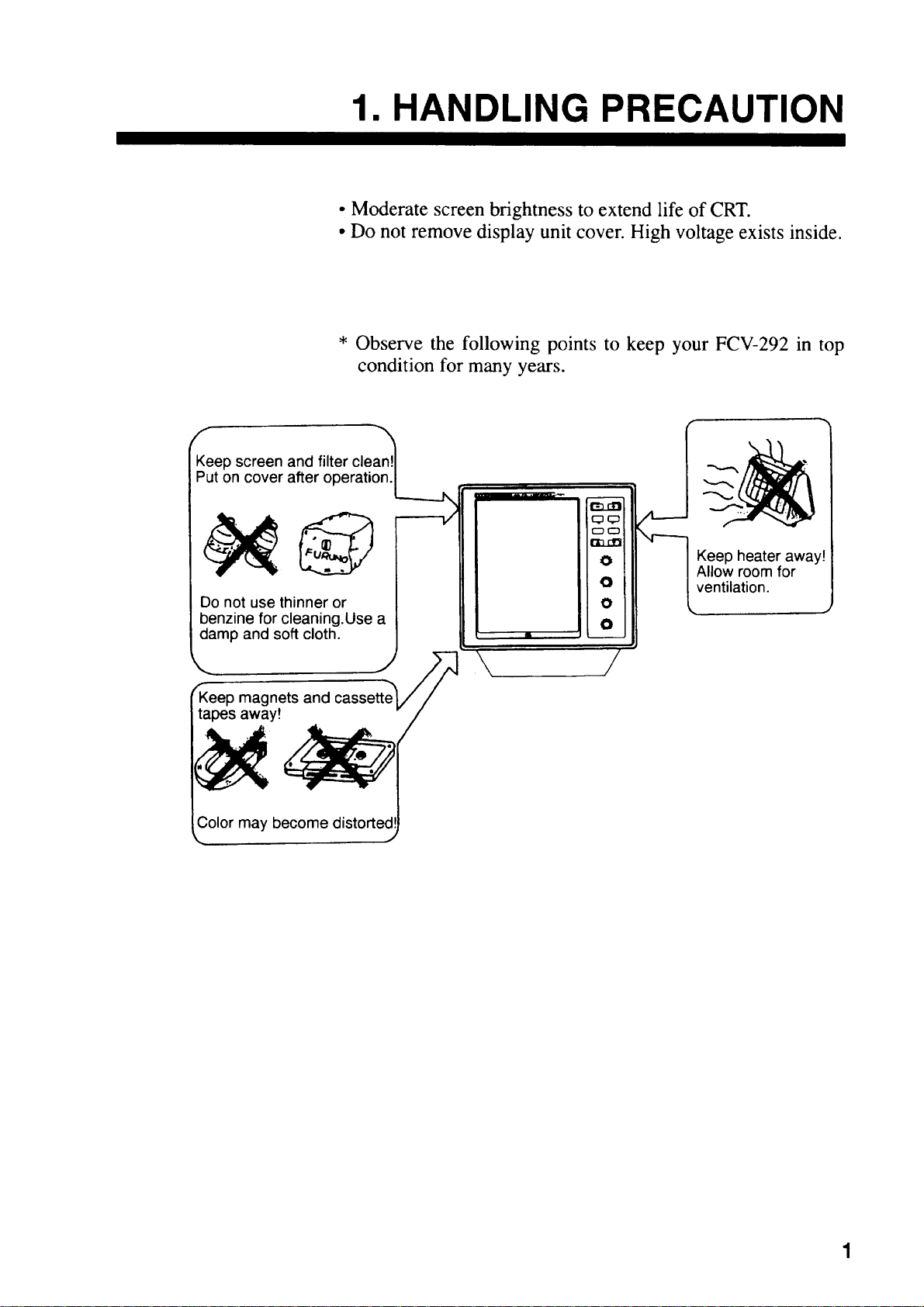
1.HANDLING PRECAUTION................................................................................1
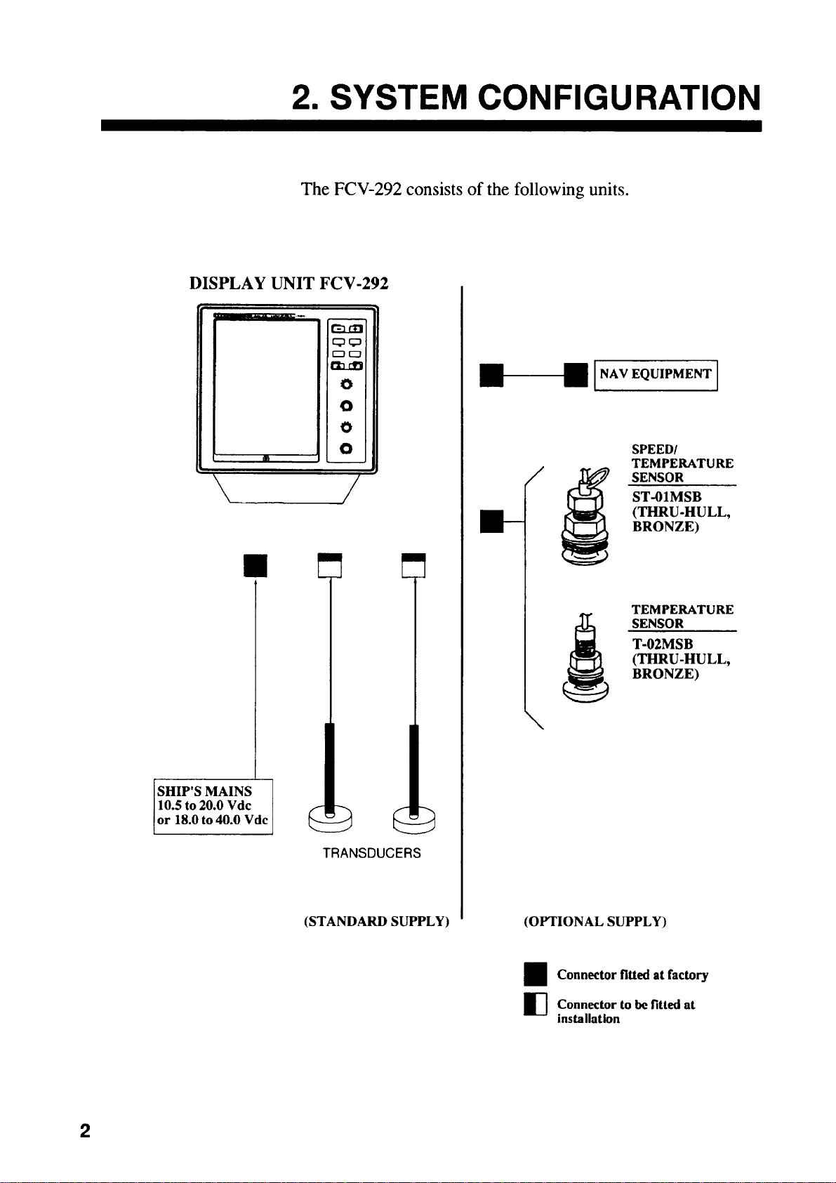
2.SYSTEM CONFIGURATION.............................................................................. 2
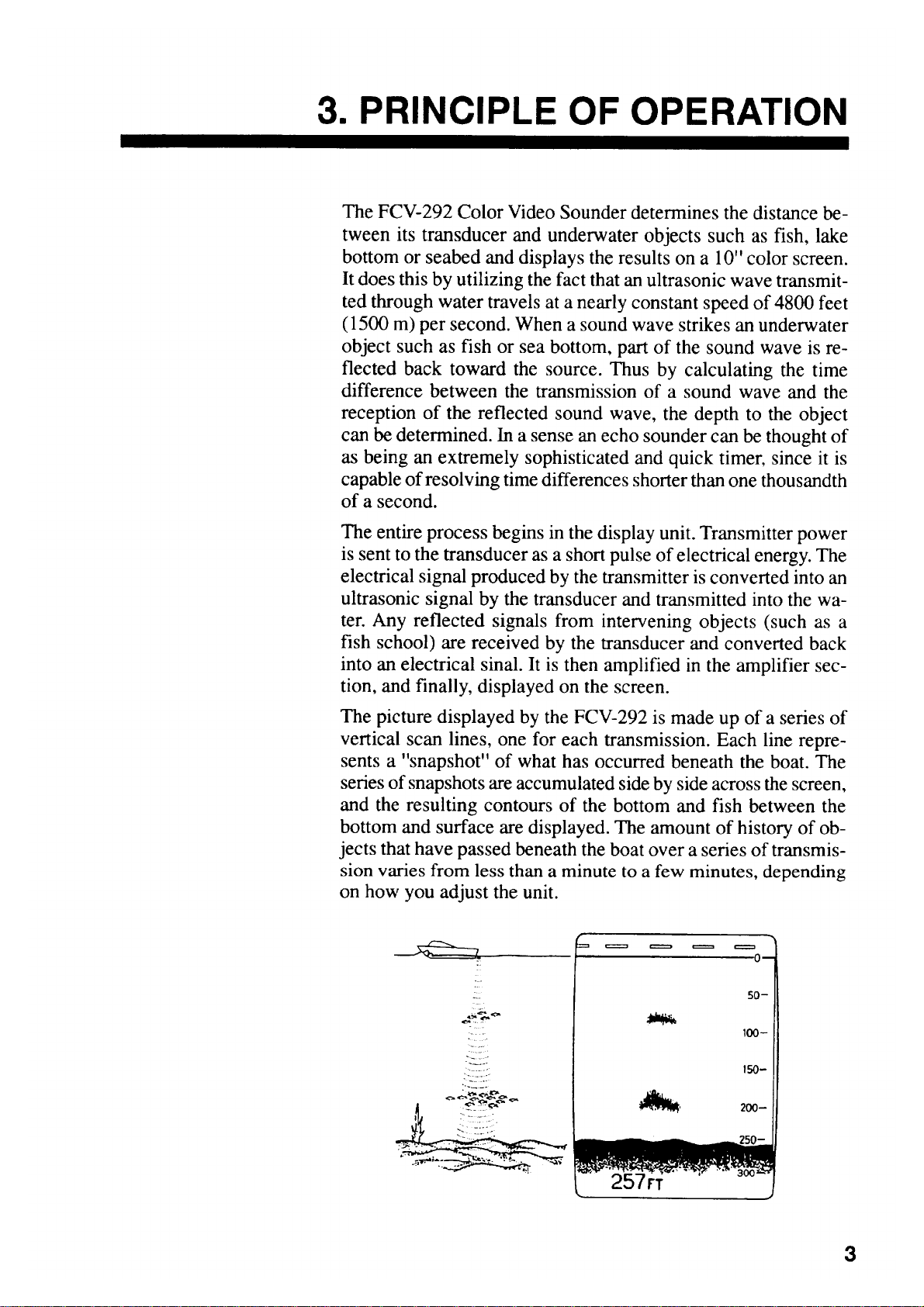
3.PRINCIPLE OF OPERATION ............................................................................3
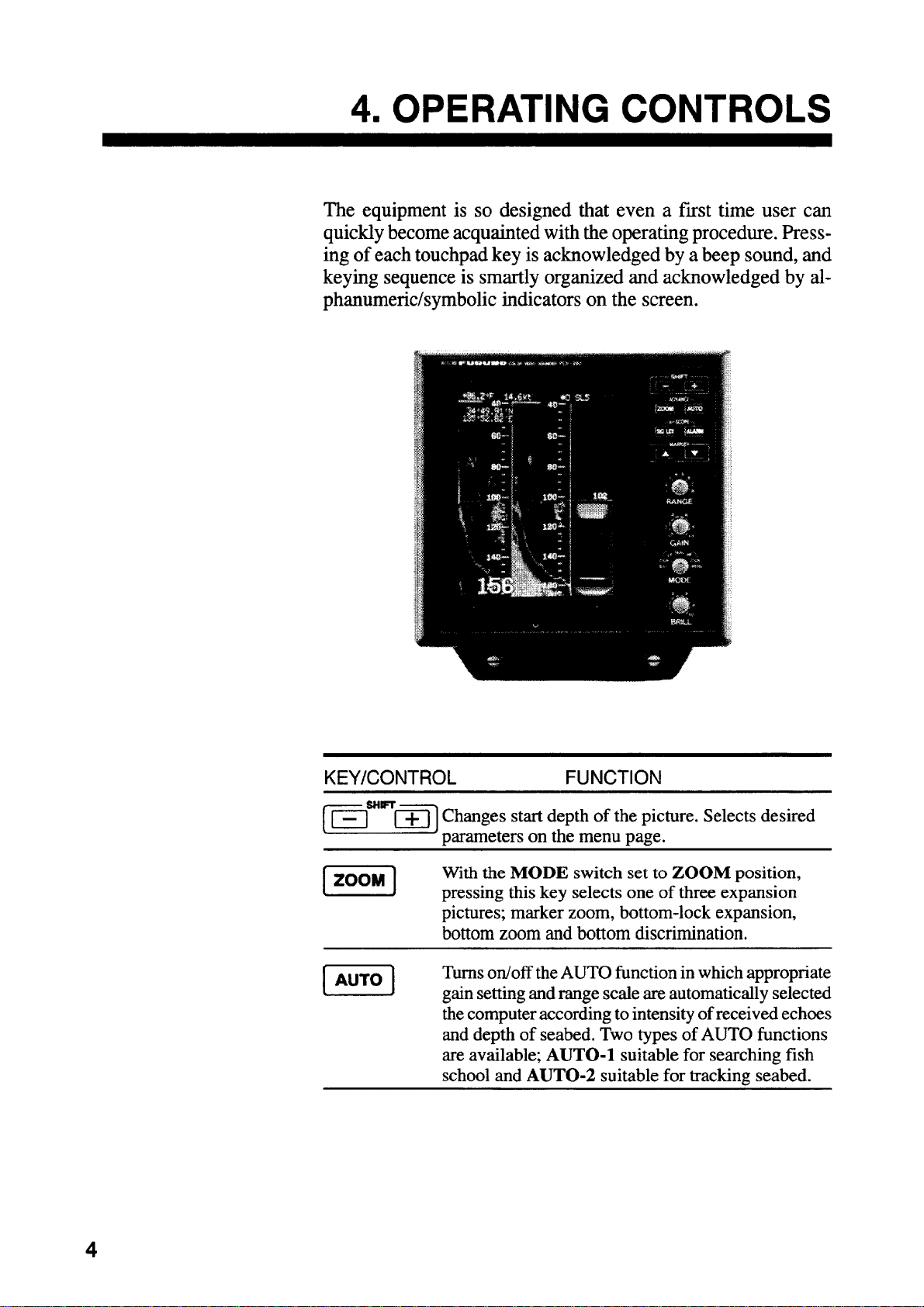
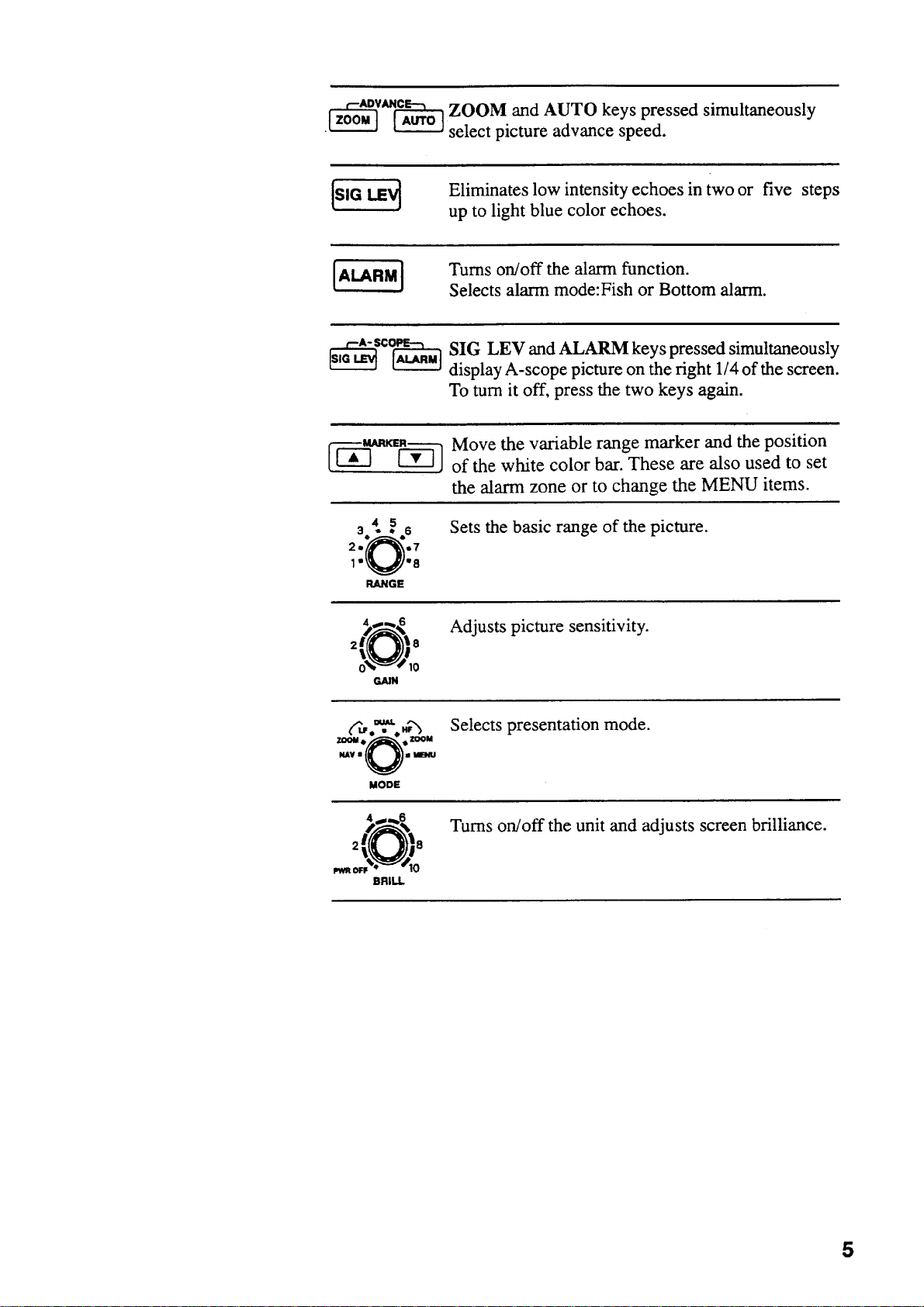
4.OPERATING CONTROLS .................................................................................4
5.BASIC OPERATION ..........................................................................................6
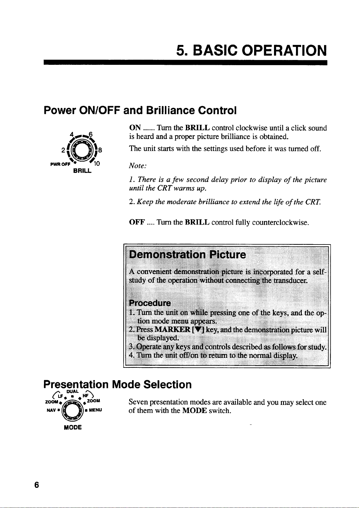
Power ON/OFF and Brilliance Control...................................................................................6
Demonstration Pictur e ...........................................................................................................6
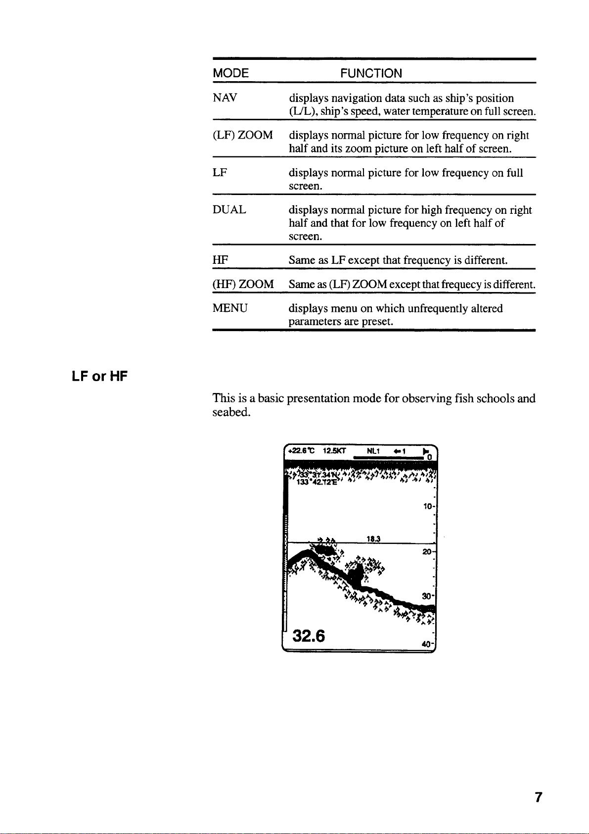
Presentation Mode Selection................................................................................................6
Zoom Pictur e Selecti on.........................................................................................................9
Automatic Operation........................................................................................................... 12
Manual Operation ...............................................................................................................12
Picture Advance Speed Selection....................................................................................... 14
Eliminating Low Intensity Echoes........................................................................................15
Turning on A-Scope Presentation .......................................................................................15
Measuring Depth to Fish School.........................................................................................15
6.FISH AND BOTTOM ALARMS........................................................................ 16
7.ADJUSTING PICTURE BY MENU ..................................................................18
Eliminating Interference (NOISE LIMITER).........................................................................18
Eliminating Low Level Noise (CLUTTER LEVEL)................................................................19
Adjusting Preset Gain.........................................................................................................19
Selecting Background Color and Echo Color (HUE SELECTION).......................................20
8.DISPLAYS ........................................................................................................21
Video Sounder Picture........................................................................................................21
Navigation Data..................................................................................................................24
9.INTERPRETING THE DISPLAY ...................................................................... 25
Frequency...........................................................................................................................25
Detecting Area....................................................................................................................25
Zero Line ............................................................................................................................26
Fish School Echoes............................................................................................................ 27
Bottom Echo.......................................................................................................................27
Surface Noise/Aeration....................................................................................................... 28
vii
Page 10

10.MAINTENANCE............................................................................................. 29
Fuse Replacement..............................................................................................................29
Cleaning ..............................................................................................................................29
Maintenance of Transducer.................................................................................................30
11.TROUBLESHOOTING ...................................................................................31
Basic Troubleshooting.........................................................................................................31
Diagnostic Self-Check.........................................................................................................33
Transducer Check...............................................................................................................34
Speed/Temperature Sensor (Option) Check........................................................................34
12.INSTALLATION..............................................................................................35
Display Unit Installation.......................................................................................................35
Transducer Installation........................................................................................................37
Tr ansd ucer Pr ep ar ation and Painti n g..................................................................................37
Speed/Temperature Sensor.................................................................................................38
Cable Connections..............................................................................................................39
13.SYSTEM MENU SETTING............................................................................. 41
Operation Procedure...........................................................................................................41
Descriptio n of Syst em Menu It em........................................................................................42
Restoring Factory Settings..................................................................................................44
14.SPECIFICATIONS.......................................................................................... 45
Complete Set.......................................................................................................................47
Installation Materials............................................................................................................48
Accessories.........................................................................................................................48
Spare Parts.........................................................................................................................48
Option..................................................................................................................................48
Transducer & Hull Bottom Installation Materials...................................................................49
APPENDIX
1. Changing T r a nsd ucer Ou tp ut Power Se tti n g.......................................................................A-1
2. Changing Transducer Frequency Specifications.................................................................A-2
3. Adjustment After Replacement of MAIN or AMP Board (entering amplifier
gain offset) ..........................................................................................................................A-4
4. Transducer 50BL-12/50BL-24H...........................................................................................A-6
5. New BLT Transducers.........................................................................................................A-7
OUTLINE DRAWING................................................................................ D-1
INTERCONNECTION DIAGRAM........................................................................... S-1
viii
Page 11
Page 12
Page 13
Page 14
Page 15
Page 16
Page 17
Page 18
Page 19
Page 20
Page 21
Page 22

Page 23

Page 24

Page 25

Page 26

Page 27

Page 28

Page 29

Page 30

Page 31

Page 32

Page 33

Page 34

Page 35

Page 36

Page 37

Page 38

Page 39

Page 40

Page 41

Page 42

Page 43

Page 44

Page 45

Page 46

Page 47

Page 48

Page 49

Page 50

Page 51

Page 52

Page 53

Page 54

Page 55

Page 56

Page 57

Page 58

Page 59

Page 60

Page 61

Page 62

Page 63

Page 64

4.Transducer 50BL-1 2/50B L- 24H
When using the transduce r 50B L-12/50B L- 24H, see thi s s ec tion.
50BL-12 cod e no.: 000-015-013
50BL-24H co de no.: 000-015-040
Transducer, thru-hull pipe and tank list
Frequency
(kHz)
50
50/200 50BL-12/200B-8B
28/50 28F-24H/50BL-24H
50/88 50BL-24H/88F-126H
Transducer
(Code No.)
50BL-12
50BL-24H
Material
Steel
FRP
Steel
FRP
Steel
FRP
Steel
FRP
Steel
FRP
Hull
Tank
(Code No.)
T-702
(000-015-041)
T-702F
(000-015-240)
T-694
(000-015-046)
T-694F
(000-015-242)
T-693
(000-015-044)
T-693F
(000-015-241)
T-696
(000-015-048)
T-696F
(000-015-244)
T-697
(000-015-239)
T-697F
(000-015-245)
Fasten inside
hull (Code No.)
TFB-5000
(000-015-206)
TRB-1000
(000-015-215)
TFB-5000
(000-015-206)
TRB-1000
(000-015-215)
TWB-6000
(000-015-207)
TRB-1100
(000-015-218)
TWB-6000
(000-015-207)
TWB-1100
(000-015-218)
TWB-6000
(000-015-207)
TWB-1100
(000-015-218)
Fasten outside
hull (Code No.)
-
-
TFB-4000
(000-015-205)
-
TWB-7000
(000-015-209)
-
TFB-7000
(000-015-209)
-
TFB-7000
(000-015-209)
-
Steel
50/200 50BL-24H/200B-12H
FRP
T-695
(000-015-047)
T-695F
(000-015-243)
TWB-6000
(000-015-207)
TRB-1100
(000-015-218)
(000-015-209)
Setting
For the loc ations of JP10 and J P 11, see page A -1.
Board Frequency (kHz) Output (kW) Transducer JP10 and JP11 setting
2 5BL-12 B 02P6204
50
MAIN
3 50BL-24H D
S1
Board Frequency (kHz)
1 2 3 4
28/50 ON ON ON ON
02P6204
50/88 ON OFF ON OFF
MAIN
50/200 ON OFF OFF ON
TFB-7000
-
A-6
Page 65

5.New BLT Transducers
A new type BLT transducer (Bolt-clam p Langevin Transducer) has been developed for this
echo sounder. The BLT transducer has large bandwidth, good sound efficiency, compact
structure and is reinfor c ed for protection against slam m ing.
28BL-6HR co de no.: 000-015-081
28BL-12HR c ode no.: 000-015-082
38BL-9HR co de no.: 000-015-083
38BL-15HR c ode no.: 000-015-092
50BL-12HR c ode no.: 000-015-093
50BL-24HR c ode no.: 000-015-094
Transducer, thru-hull pipe and tank list
Frequency
(kHz)
28/200 28BL-6HR/200B-8B
38/200 38BL-9HR/200B-8B
50/200 50BL-12HR/200B-8B
28/38 28BL-12HR/38BL-15HR
28/50 28BL-12HR/50BL-24HR
Transducer
Hull
Material
Steel
FRP
Steel
FRP
Steel
FRP
Steel
FRP
Steel
FRP
Tank
(Code No.)
T-693
(000-015-044)
T-693F
(000-015-241)
T-693
(000-015-044)
T-693F
(000-015-241)
T-693
(000-015-044)
T-693F
(000-015-241)
T-681
(000-015-849)
T-681F
(000-015-850)
T-681
(000-015-849)
T-681F
(000-015-850)
Fasten inside
hull (Code No.)
TWB-6000 (2)
(000-015-207)
TRB-1100 (2)
(000-015-219)
TWB-6000 (2)
(000-015-207)
TRB-1100 (2)
(000-015-219)
TWB-6000 (2)
(000-015-207)
TRB-1100 (2)
(000-015-219)
TWB-6000 (2)
(000-015-207)
TRB-1100 (2)
(000-015-219)
TWB-6000 (2)
(000-015-207)
TRB-1100 (2)
(000-015-219)
Fasten outside
hull (Code No.)
TFB-7000 (2)
(000-015-209)
-
TFB-7000 (2)
(000-015-209)
-
TFB-7000 (2)
(000-015-209)
-
TFB-7000 (2)
(000-015-209)
-
TFB-7000 (2)
(000-015-209)
-
Steel
38/50 38BL-15HR/50BL-24HR
FRP
Steel
28/88 28BL-12HR/88F-126H
FRP
T-681
(000-015-849)
T-681F
(000-015-850)
T-682
(000-015-851)
T-682F
(000-015-852)
TWB-6000 (2)
(000-015-207)
TRB-1100 (2)
(000-015-219)
TWB-6000 (2)
(000-015-207)
TRB-1100 (2)
(000-015-219)
TFB-7000 (2)
(000-015-209)
-
TFB-7000 (2)
(000-015-209)
-
A-7
Page 66

NEW BLT TRANSDUCERS
Steel
38/88 38BL-15HR/88F-126H
FRP
Steel
50/88 50BL-24HR/88-126H
FRP
Steel
28/200 28BL-12HR/200B-12H
FRP
Steel
38/200 38BL-15HR/200B-12H
FRP
Steel
50/200 50BL-24HR/200B-12H
FRP
T-682
(000-015-851)
T-682F
(000-015-852)
T-682
(000-015-851)
T-682F
(000-015-852)
T-683
(000-015-853)
T-683F
(000-015-854)
T-683
(000-015-853)
T-683F
(000-015-854)
T-683
(000-015-853)
T-683F
(000-015-854)
TWB-6000 (2)
(000-015-207)
TRB-1100 (2)
(000-015-219)
TWB-6000 (2)
(000-015-207)
TRB-1100 (2)
(000-015-219)
TWB-6000 (2)
(000-015-207)
TRB-1100 (2)
(000-015-219)
TWB-6000 (2)
(000-015-207)
TRB-1100 (2)
(000-015-219)
TWB-6000 (2)
(000-015-207)
TRB-1100 (2)
(000-015-219)
TFB-7000 (2)
(000-015-209)
-
TFB-7000 (2)
(000-015-209)
-
TFB-7000 (2)
(000-015-209)
-
TFB-7000 (2)
(000-015-209)
-
TFB-7000 (2)
(000-015-209)
-
28/150 28BL-12HR/150B-12H
38/150 38BL-15HR/150-12H
38/150 50BL-24HR/156-12H
Steel
FRP
Steel
FRP
Steel
FRP
T-683
(000-015-853)
T-683F
(000-015-854)
T-683
(000-015-853)
T-683F
(000-015-854)
T-683
(000-015-853)
T-683F
(000-015-854)
TWB-6000 (2)
(000-015-207)
TRB-1100 (2)
(000-015-219)
TWB-6000 (2)
(000-015-207)
TRB-1100 (2)
(000-015-219)
TWB-6000 (2)
(000-015-207)
TRB-1100 (2)
(000-015-219)
TFB-7000 (2)
(000-015-209)
-
TFB-7000 (2)
(000-015-209)
-
TFB-7000 (2)
(000-015-209)
-
A-8
Page 67

NEW BLT TRANSDUCERS
A
Setting
For the locations of JP10 and JP11, see page A-1.
Board Fr equency (kHz) O u t put (kW) Transducer JP10 and JP11 setting
28
02P6204
MAIN
38
50
Board Frequency (kHz)
28/50 ON ON ON ON
02P6204
MAIN
38/50 OFF ON ON ON
50/88 ON OFF ON OFF
50/200 ON OFF OFF ON
2 28BL-6HR B
3 28BL-12HR C
2 38BL-9HR C
3 38BL-15HR E
2 50BL-12HR D
3 50BL-24HR E
S1
1 2 3 4
-9
Page 68

Page 69

321
Oct. 1, '02
S-1
A
B
C
指示器
DISPLAY UNIT
CV‑291/292
NMEA
J4
TXD‑H
TXD‑C
RXD‑H
RXD‑C
NC
SHIELD
SPEED/TEMP
J5
GND
VTH‑H
VTH‑C
SPD
+10V
POWER
J3
(+)
(‑)
GND
MJ‑A6SPFD
1
2
3
4
5
6
MJ‑A6SPFD
1
2
3
4
5
6
MJ‑A3SPFD
1
2
3
MJ‑A6SPF0012,5m
P
P
8m
P
FUSE
7A: 12V
3A: 24/32V
シロ WHT
クロ BLK
航法装置
NAV AID
船速・水温センサー
SPEED/TEMP SENSOR
ST‑01MSB
T‑02MSB
MJ‑A3SPF0013,3.5m,φ6
船内電源
SHIP'S MAINS
12/24‑32 VDC
D
DRAWN
Sep. 30 '02
CHECKED
Oct. 1 '02
APPROVED
SCALE
DWG.No.
J1 J2
*3
注記
*1)造船所手配
*2)工場にて接続済み
*3)FCV‑292のみ
T.YAMASAKI
Y.KIMURA
MASS
kg
C2351‑C01‑ F
TX‑HTX‑L
NCS‑254PNCS‑254P
送受波器送受波器
XDCRXDCR
NOTE
*1: SHIPYARD SUPPLY.
*2: FITTED AT FACTORY.
*3: ONLY FOR FCV‑292.
GND
IV‑2.0SQ
21
整流器
RECTIFIER
PR‑62
56
43214321
DPYC‑1.5 *1
100/110/220 VAC
50/60 Hz, 1φ
TITLE
名称
FCV‑291/292
カラー魚群探知機
相互結線図
NAME
COLOR VIDEO SOUNDER
INTERCONNECTION DIAGRAM
 Loading...