

Page 1

COLOR LCD SOUNDER
FCV-1200L/1200LM
Page 2

9-52 Ashihara-cho,9-52 Ashihara-cho,
A
A
*00080900500**00080900500*
*00080900500**00080900500*
*OME23650L00**OME23650L00*
Nishinomiya, JapanNishinomiya, Japan
Telephone :Telephone : 0798-65-21110798-65-2111
Telefax :Telefax : 0798-65-42000798-65-4200
Your Local Agent/DealerYour Local Agent/Dealer
ll rights reserved.
ll rights reserved.
PUB.No.PUB.No. OME-23650OME-23650
(( DAMIDAMI ))
FCV-1200L/LMFCV-1200L/LM
Printed in JapanPrinted in Japan
FIRST EDITION :FIRST EDITION : APR.APR. 20002000
L :L : JUN.JUN. 10,200210,2002
* 0 0 0 8 0 9 0 0 5 0 0 ** 0 0 0 8 0 9 0 0 5 0 0 *
*OME23650L00**OME23650L00*
* O M E 2 3 6 5 0 L 0 0 ** O M E 2 3 6 5 0 L 0 0 *
Page 3
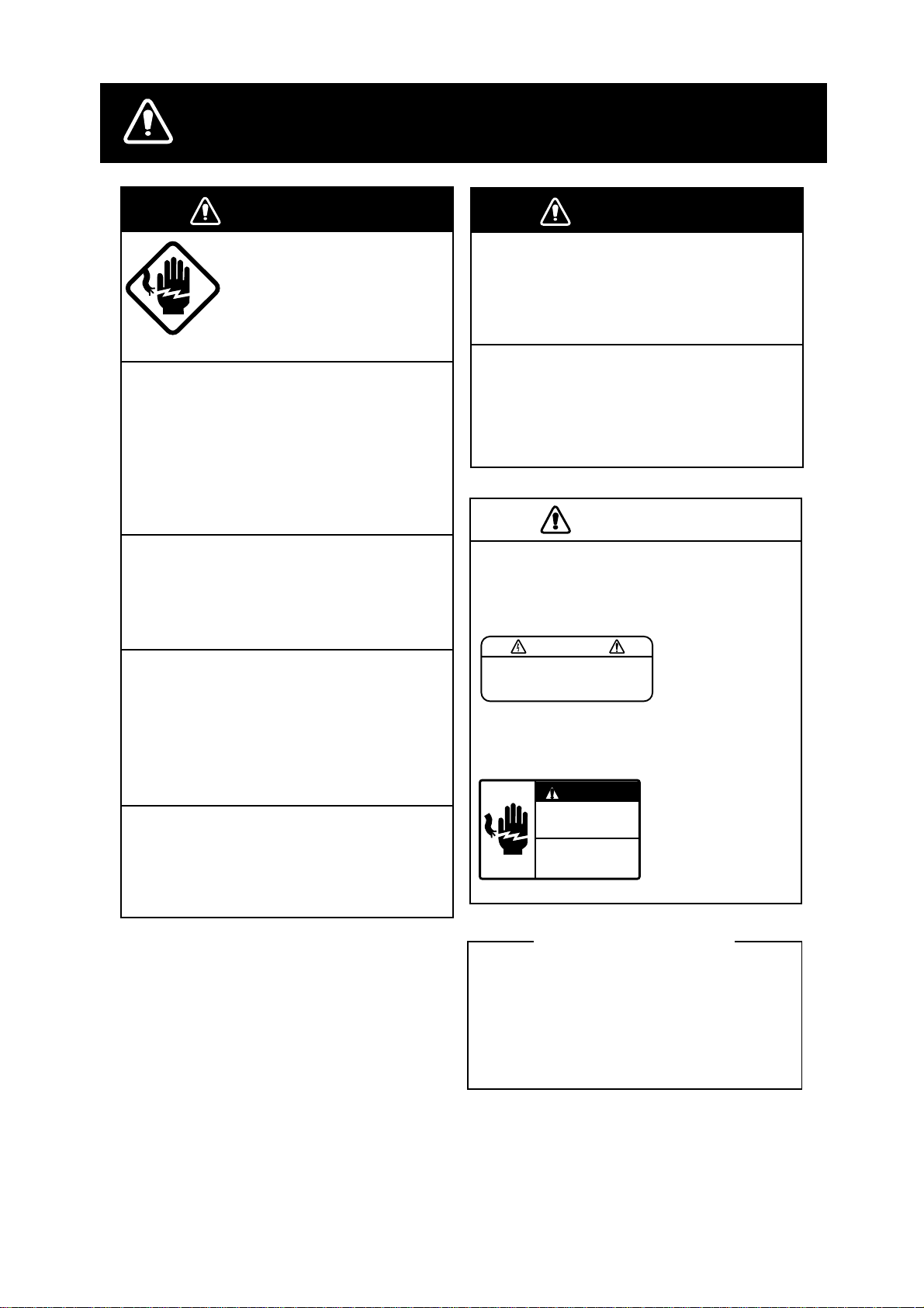
SAFETY INSTRUCTIONS
WARNING
ELECTRICAL SHOCK HAZARD
Do not open the equipment.
Only qualified personnel
should work inside the
equipment.
Immediately turn off the power at the
switchboard if water leaks into the
equipment or something is dropped in
the equipment.
Continued use of the equipment can cause
fire or electrical shock. Contact a FURUNO
agent for service.
Do not disassemble or modify the
equipment.
Fire, electrical shock or serious injury can
result.
Immediately turn off the power at the
switchboard if the equipment is emitting
smoke or fire.
Continued use of the equipment can cause
fire or electrical shock. Contact a FURUNO
agent for service.
Make sure no rain or water splash leaks
into the equipment.
WARNING
Keep heater away from equipment.
A heater can melt the equipment's power
cord, which can cause fire or electrical
shock.
Use the proper fuse.
Fuse rating is shown on the equipment.
Use of a wrong fuse can result in equipment
damage.
CAUTION
A warning label is attached to the equipment. Do not remove the label. If the
label is missing or illegible, contact
a FURUNO agent or dealer.
WARNING
To avoid electrical shock, do not
remove cover. No user-serviceable
parts inside.
DANGER
Electrical shock hazard.
Power off control unit
and unplug CN2 before
servicing.
(Processor unit)
Name: Warning Label (1)
Type: 86-003-1011-0
Code No.: 100-236-230
(Monitor unit)
Name: Warning Label (2)
Type: 03-129-1001-0
Code No.: 100-236-740
(Processor unit)
Name: Power Warning
Label
Type: 02-127-2002-0
Code No.: 100-283-240
Fire or electrical shock can result if water
leaks in the equipment.
About the TFT LCD
The TFT LCD is constructed using the
latest LCD techniques, and displays
99.99% of its pixels. The remaining 0.01%
of the pixels may drop out or blink, however this is not an indication of malfunction.
i
Page 4

FOREWORD
A Word to FCV-1200L/1200LM Owners
Congratulations on your choice of the FURUNO FCV-1200L/FCV-1200LM COLOR LCD
SOUNDER. We are confident you will see why the FURUNO name has become synonymous
with quality and reliability.
FCV-1200L is a dual-frequency color LCD sounder, and FCV-1200LM is a monitor which
displays the signal from an external video sounder.
For over 50 years FURUNO Electric Company has enjoyed an enviable reputation for innovative
and dependable marine electronics equipment. This dedication to excellence is furthered by our
extensive global network of agents and dealers.
This equipment is designed and constructed to meet the rigorous demands of the marine
environment. However, no machine can perform its intended function unless installed, operated
and maintained properly. Please carefully read and follow the recommended procedures for
operation and maintenance.
We would appreciate hearing from you, the end-user, about whether we are achieving our
purposes.
Thank you for considering and purchasing FURUNO equipment.
Features
•
8- or 16- color presentation (including background) provides detailed information on fish
density and bottom composition, on a 10.4 inch color LCD.
•
Furuno Free Synthesizer (FFS) transceiver design allows use of user-selectable operating
frequencies.
•
You can select display orientation; Portrait (vertical) or Landscape (horizontal).
•
Automatic bottom tracking features permits unattended operation.
•
Frequency mixing picture helps discriminate fish species.
•
Alarms: Fish, Bottom, Fish-Bottom, Water Temperature (temperature data required).
•
A-scope presentation displays echoes at each transmission with amplitudes and colors
according to intensities.
•
Unique split range control allows independent range settings in dual-frequency mode.
ii
Page 5

TABLE OF CONTENTS
FOREWORD...................................................................................................................ii
INDICATIONS .................................................................................................................v
SYSTEM CONFIGURATION .........................................................................................vi
1. BASIC OPERATION ............................................................................................ 1-1
1.1 Key/Control Operation ...............................................................................................................1-1
1.2 Turning the Power On/Off.......................................................................................................... 1-3
1.3 Adjusting the Brilliance of LCD and Key Panel .........................................................................1-3
1.4 Presentation Mode ....................................................................................................................1-4
1.5 Selecting Basic Range ............................................................................................................ 1-11
1.6 Shifting the Basic Range .........................................................................................................1-12
1.7 Adjusting Gain .........................................................................................................................1-13
1.8 Measuring Depth .....................................................................................................................1-13
1.9 Marker Line.............................................................................................................................. 1-14
1.10 Adjusting Clutter ......................................................................................................................1-15
1.11 Adjusting TVG .........................................................................................................................1-16
1.12 Eliminating Weak Echoes ........................................................................................................1-18
1.13 Picture Advance Speed ...........................................................................................................1-19
1.14 A-Scope Display ......................................................................................................................1-21
1.15 Suppressing Interference ........................................................................................................ 1-22
1.16 Adjusting the External Video Sounder Picture ........................................................................1-24
2. MENU OPERATION............................................................................................. 2-1
2.1 Basic Menu Operation ............................................................................................................... 2-1
2.2 DISP Menu ................................................................................................................................2-3
2.3 ALM Menu .................................................................................................................................2-6
2.4 TX/RX Menu ..............................................................................................................................2-9
2.5 USER-1/2 Menu ...................................................................................................................... 2-11
iii
Page 6

3. SYSTEM MENU................................................................................................... 3-1
3.1 SYSTEM Menu Operation ......................................................................................................... 3-1
3.2 SYSTEM SETTING Menu .........................................................................................................3-2
3.3 ES/DRAFT SETTING Menu ......................................................................................................3-4
3.4 RANGE SETTING Menu ...........................................................................................................3-7
3.5 TEMP SETTING Menu ..............................................................................................................3-9
3.6 NET SONDE SETTING Menu .................................................................................................3-10
3.7 USER COLOR SETTING Menu ..............................................................................................3-13
3.8 USER CLUTTER SETTING Menu ..........................................................................................3-15
3.9 NAV DATA SETTING Menu.....................................................................................................3-16
3.10 TARGET ECHO SETTING Menu ............................................................................................3-17
4. INTERPRETING THE DISPLAY .......................................................................... 4-1
4.1 Color Bar....................................................................................................................................4-1
4.2 Zero Line....................................................................................................................................4-2
4.3 Bottom Echoes ..........................................................................................................................4-2
4.4 Fish Schools .............................................................................................................................. 4-3
4.5 Other Echoes............................................................................................................................. 4-4
5. MAINTENANCE & TROUBLESHOOTING.......................................................... 5-1
5.1 Maintenance ..............................................................................................................................5-1
5.2 Fuse Replacement ....................................................................................................................5-2
5.3 Troubleshooting ......................................................................................................................... 5.3
5.4 Diagnostic Test .......................................................................................................................... 5-4
5.5 Test Pattern ...............................................................................................................................5-6
5.6 Default Setting ...........................................................................................................................5-7
APPENDIX 1 MENU TREE...................................................................................AP-1
APPENDIX 2 SCREEN DIVISION ........................................................................AP-6
APPENDIX 3 DISPLAY DIVISION........................................................................AP-9
INDEX ........................................................................................................................ IN-1
iv
Page 7
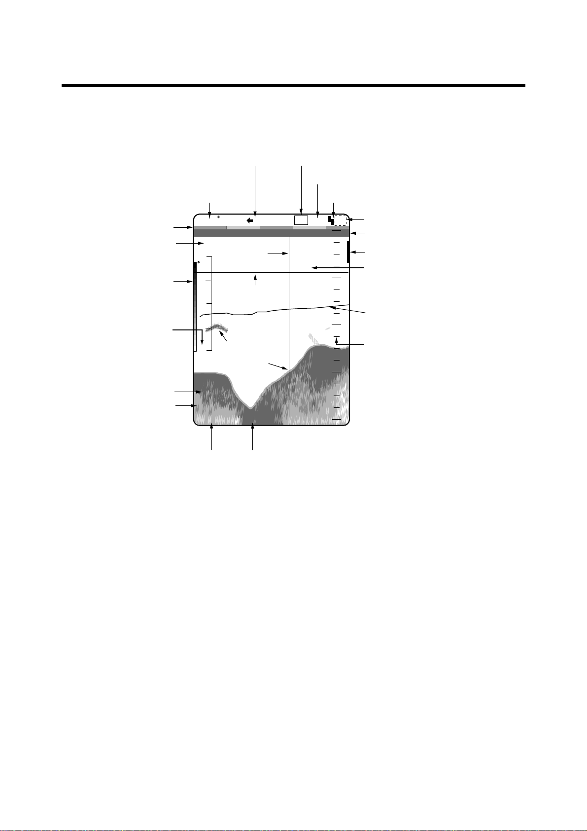
INDICATIONS
The illustration below shows the indications as they appear on the portrait-type monitor unit.
Their locations are also the same on the landscape-type monitor unit. This manual shows all
display screen illustrations using the portrait-type monitor unit.
Water temperature
Minute marker
Elapsed time
Color bar
Temperature scale*
Ship's speed*
Depth
Picture advance speed
5.3 F
x H xx M
10
F
1/1
Marker
line
VRM marker
5
Fish school
0
Seabed
17.8kt
49.6
1'21" <P/R>
ft
Frequency
Noise limiter
LF
N1
19.7
20
40
60
80
Shift
0
0
Alarm
Zero line
Alarm marker
VRM Depth
Water temperature gr aph*
Depth scale
*: Appropriate sensors required
Scroll time
Transducer power reduction (FCV -1200L only)
v
Page 8
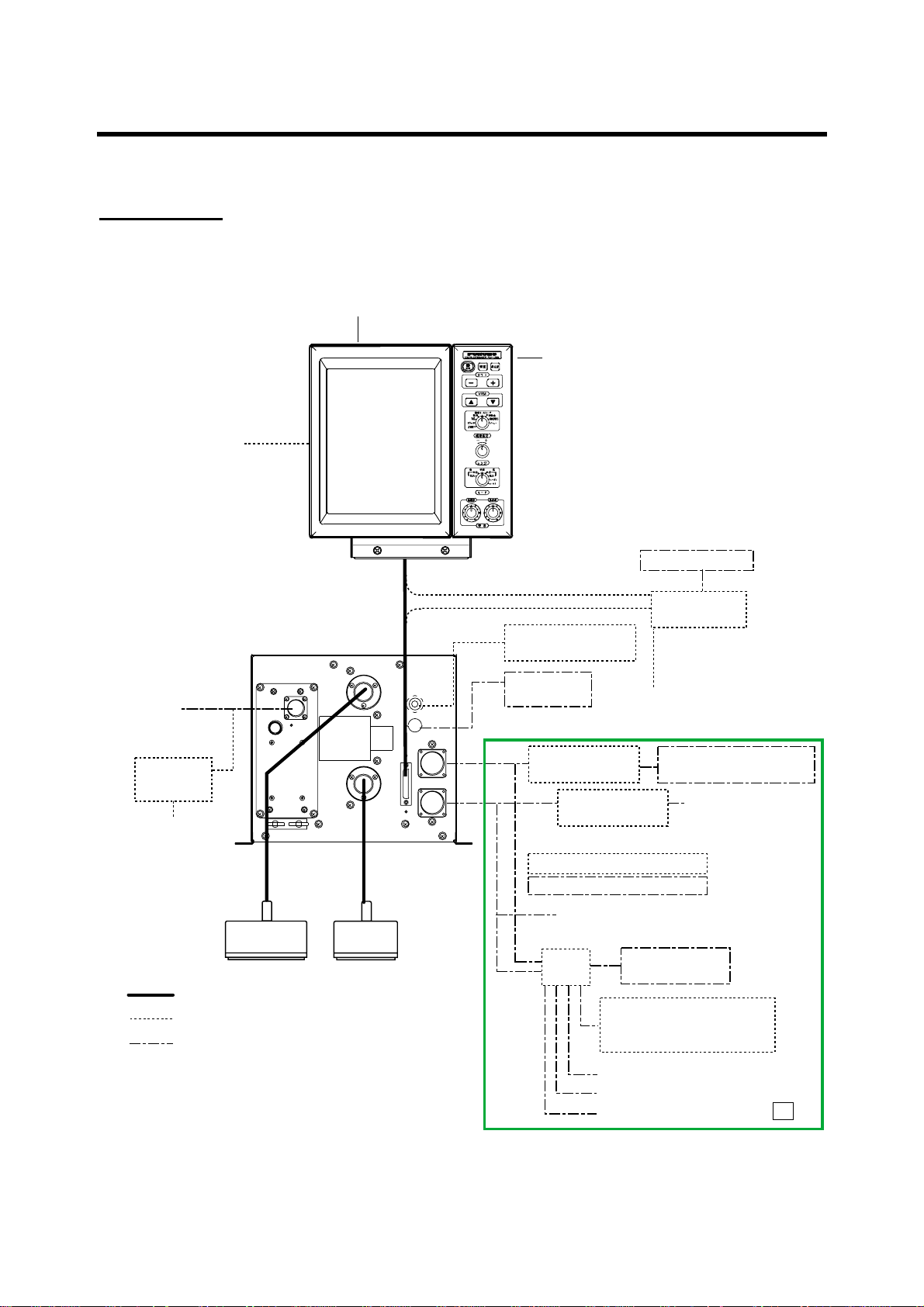
SYSTEM CONFIGURATION
Note: This equipment is intended for marine use only.
Standard type
Monitor unit MU-101C is supplied as standard. The illustration be low shows the portrait-type
monitor unit and control unit.
MONITOR UNIT MU-101C
CONTROL UNIT
CV-1201: Portrait type
CV-1202: Landscape type
Navigator *4
Ship's Mains
12-24 VDC
Rectifier
RU-1746B-2
100/110/115/200/
220/230 V AC
1φ, 50/60 Hz
NMEA 0183
PROCESSOR UNIT
CV-1203 (FCV-1200L)
CV-1203M (FCV-1200LM)
HI
LO
Water Temp. Sensor
(T-02MSB, etc.)
Net Sonde
FNZ-18
E/S Interface
OR
Transceiver Unit ETR-5D/10D
T elesounder TS-7000/8000 *3
Navigator *4
VI-1100A
E/S Interface
VI-1100A
External Monitor
Interface Unit
IF-8000
Sonar, Net Recorder,
Telesounder TS-50/80 *3
Same as above
High
Frequency
Transducer*1
: Standard
: Option
: Local Supply
*1: FCV-1200L only
*2: EXIF Assy. required for FCV-1200L.
*3: For sister ship one unit only
Sister ship: EXIF Assy. required for FCV-1200L
Master ship: FCV-1200LM or FCV-1200L equipped with EXIF Assy.
*4: Navigator may be connected to interface unit or monitor unit.
vi
Low
Frequency
Transducer*1
Same as above
OR
Switch Box
EX-7
Picture Recorder
MT-12
E/S Interface VI-1100A
OR
Transmitter Unit ETR-5D/10D
Same as above
Same as above
Same as above
*2
Page 9
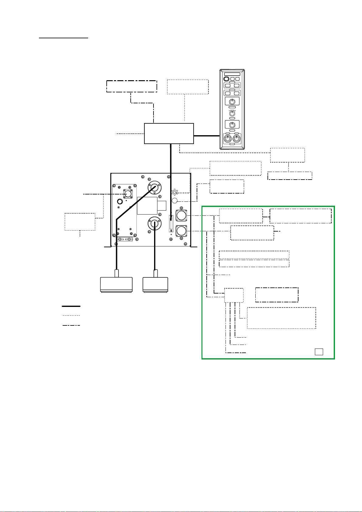
Blackbox type
Monitor unit MU-101C is not supplied. The external monitor is required. Connect the control unit
CV-1201 or CV-1202 to the interface unit IF-8000.
Ship's Mains
12-24 VDC
Rectifier
RU-1746B-2
100/110/115/200/
220/230 V AC
1φ, 50/60 Hz
External Monitor
Navigator
PROCESSOR UNIT
CV-1203 (FCV-1200L)
CV-1203M (FCV-1200LM)
NMEA 0183
MONITOR UNIT
MU-101C
Interface Unit
IF-8000
HI
LO
CONTROL UNIT
*4
Water Temp. Sensor
(T-02MSB, etc.)
Net Sonde
FNZ-18
E/S Interface
VI-1100A
OR
Transceiver Unit ETR-5D/10D
T elesounder TS-7000/8000 *3
CV-1201: Portrait type
CV-1202: Landscape type
E/S Interface
VI-1100A
Interface Unit
IF-8000
External Monitor
Sonar, Net Recorder,
Telesounder TS-50/80 *3
Same as above
High
Frequency
Transducer*1
: Standard
: Option
: Local Supply
*1: FCV-1200L only
*2: EXIF Assy. required for FCV-1200L.
*3: For sister ship one unit only
Sister ship: EXIF Assy. required for FCV-1200L
Master ship: FCV-1200LM or FCV-1200L equipped with EXIF Assy.
*4: When connecting optional monitor unit, connect it to control unit.
Low
Frequency
Transducer*1
Same as above
OR
Switch Box
EX-7
Picture Recorder
MT-12
E/S Interface VI-1100A
OR
Transceiver Unit ETR-5D/10D
Same as above
Same as above
Same as above
*2
vii
Page 10

This page is intentionally left blank .
Page 11
1. BASIC OPERATION
1.1 Key/Control Operation
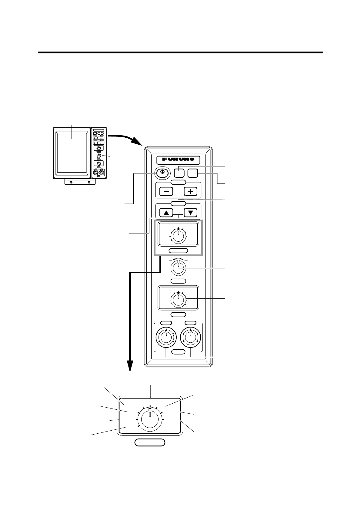
1.1.1 Portrait-type control unit
Monitor Unit
Correct key operation:One beep
Wrong key operation: Two beeps
Control
Unit
Turns power on/off.
(P. 1-3)
• Shifts VRM/WHITE
MARKER. (P. 1-13)
• Selects menu item.
(P. 2-1)
COLOR LCD SOUNDER FCV– 1200L
BRILL
PWR
SHIFT
VRM
ADVANCE/A-SCOPE
SIG LEVEL
TVG
CLUTTER
EXIT
ZOOM ZOOM
LF HF
46
28
0
NL
GAIN-EXT
FUNCTION
RANGE
DUAL
HF
LF
USER-2
MODE
46
28
10
0
GAIN
MENU
USER-1
MARKER
TLL
10
Adjusts dimmer of the display
and control panel. (P. 1-3)
Inscribes marks on the display
(P. 1-14).
• Shifts the display area.
(P. 1-12)
• Changes the menu setting.
(P. 2-1)
Selects a display range. (P. 1-11)
Selects a display.
(P. 1-4)
Adjusts gain of high and low
frequencies individually. (P. 1-13)
Opens the SIGNAL
LEVEL menu.
(P. 1-18)
Opens the TVG
menu. (P. 1-16)
Opens the CLUTTER
menu. (P. 1-15)
Closes menus.
Opens the PIC ADVANCE/A-SCOPE menu.
(P. 1-19, 1-21)
Opens the NOISE
ADVANCE/A-SCOPE
SIG LEVEL
TVG
CLUTTER
EXIT
NL
GAIN-EXT
MENU
LIMITER menu. (P. 1-22)
Opens the EXTERNAL
ECHO menu. (P. 1-24)
Opens the main menu. (P. 2-1)
FUNCTION
Control unit (Portrait type)
1-1
Page 12
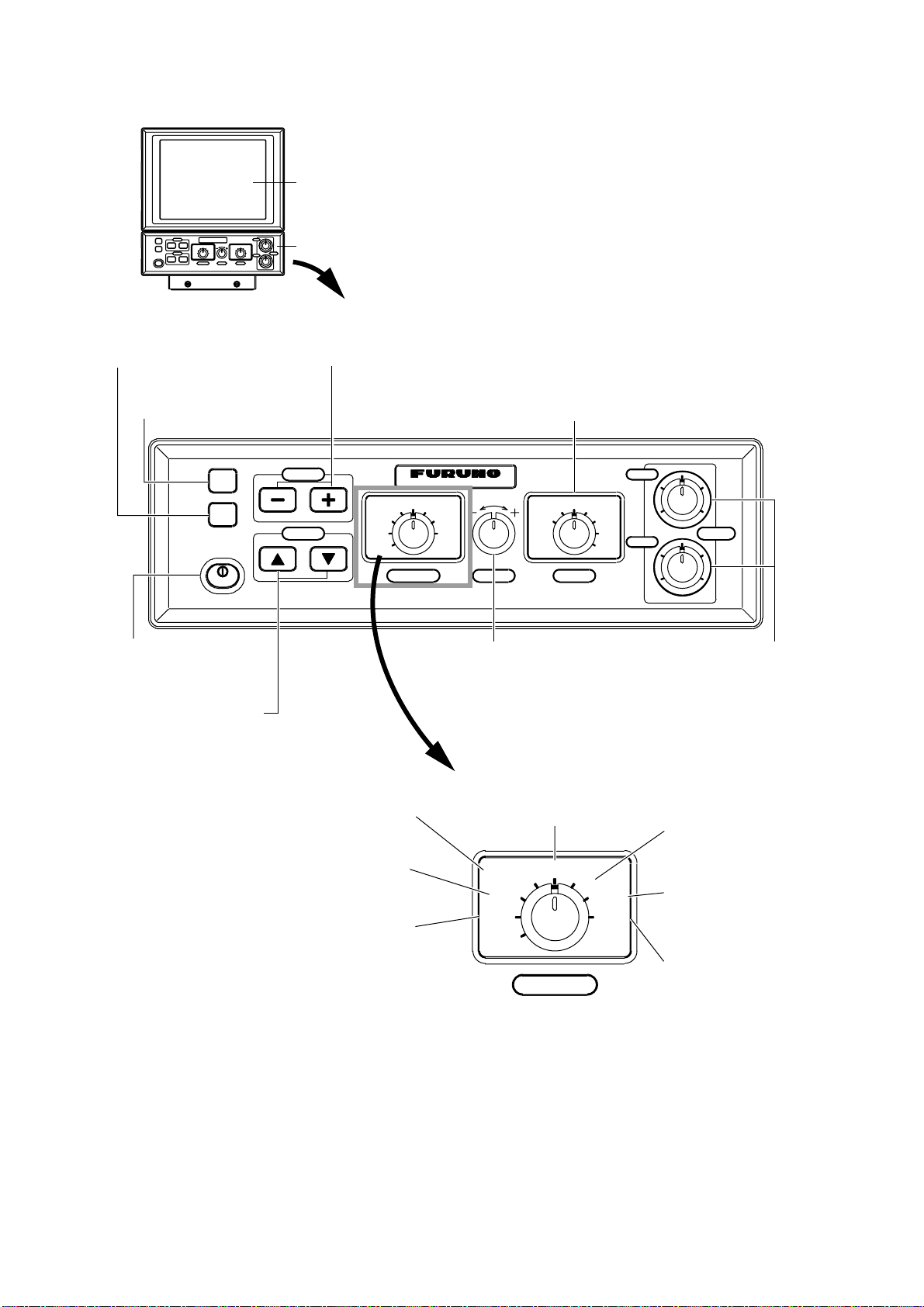
1.1.2 Landscape-type control unit
Monitor Unit
Adjusts dimmer of the
display and control
panel (P. 1-13).
Inscribes marks
on the display
(P. 1-14).
MARKER
TLL
BRILL
PWR
Turns power on/off.
(P.1-3)
· Shifts VRM/WHITE
MARKER. (P. 1-13)
· Selects menu item.
(P. 2-1)
Control Unit
· Shifts the display area. (P. 1-12)
· Changes menu setting. (P. 2-1)
SHIFT
VRM
COLOR LCD SOUNDER FCV– 1200L
ADVANCE/A-SCOPE
SIG LEVEL
TVG
CLUTTER
EXIT
NL
FUNCTION
GAIN-EXT
MENU
RANGE
Selects the
display range. (P. 1-11)
Opens the SIGNAL
LEVEL menu.
(P. 1-18)
Opens the TVG
menu. (P. 1-16)
Opens the CLUTTER
menu. (P. 1-15)
SIG LEVEL
TVG
CLUTTER
EXIT
Correct key operation:One beep
Wrong key operations:Two beeps
Selects the display.
(P.1-4)
HF
4
6
28
0
10
LF
4
6
28
0
10
GAIN
ZOOM
LF
MODE
DUAL
HF
ZOOM
USER1
USER2
Adjusts gain of high and
low frequencies individually.
(P. 1-13)
Opens the PIC ADVANCE/A-SCOPE
menu.(P. 1-19, 1-21)
Opens the NOISE
LIMITER menu.
ADVANCE/A-SCOPE
NL
GAIN-EXT
MENU
(P. 1-22)
Opens the
EXTERNAL
ECHO menu. (P. 1-24)
Opens the main
FUNCTION
menu. (P. 2-1)
1-2
Control unit (Landscape type)
Page 13
1.2 Turning the Power On/Off
1. Press the [PWR] key to turn the power on.
Beep sounds, and then th e pow er t urns on. The display selected with the [MODE] swit ch
appears.
2. Press the [PWR] key again to turn the power off.
Note: Wait for five seconds before turning on the power again.
1.3 Adjusting the Brilliance of LCD and Key Panel
The brilliance of the LCD and the dimmer of key panel may be adjusted as below. The LCD
brilliance is adjustable 10 steps; the panel dimmer in 5 steps.
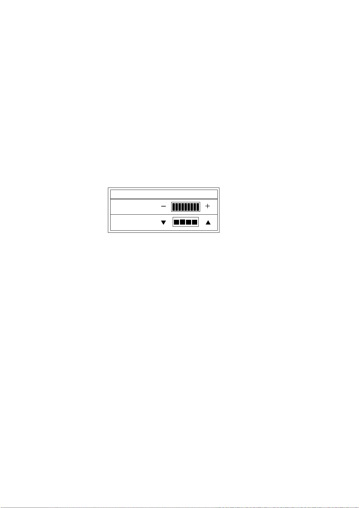
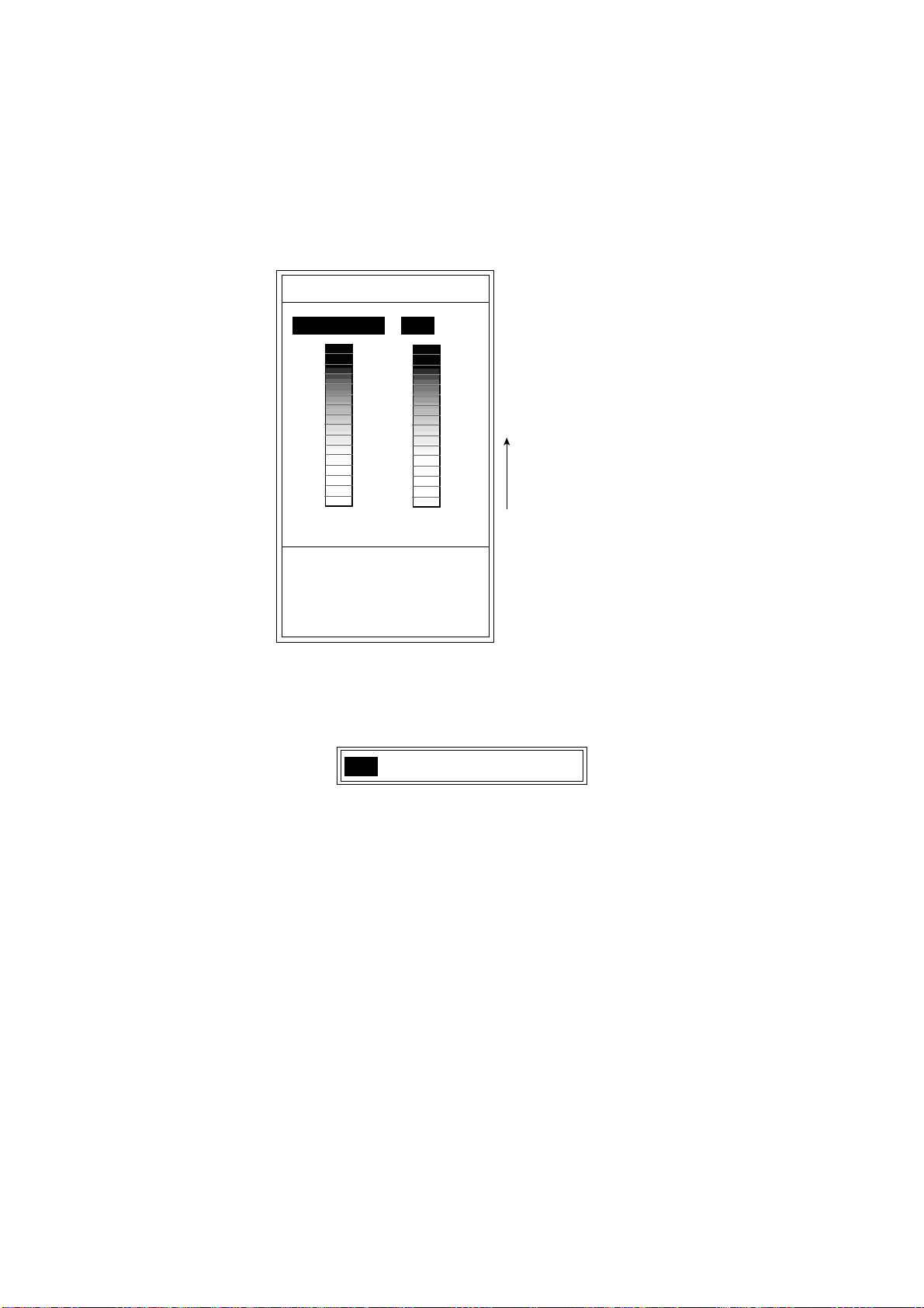
1. Press the [BRILL] key to open the BRILL/PANEL DIMMER window.
BRILL/PANEL DIMMER
B R I L L (9)
PANEL DIM (4)
Note: Location of arrow keys on the brilliance setting
window is opposite of same controls on the control unit.
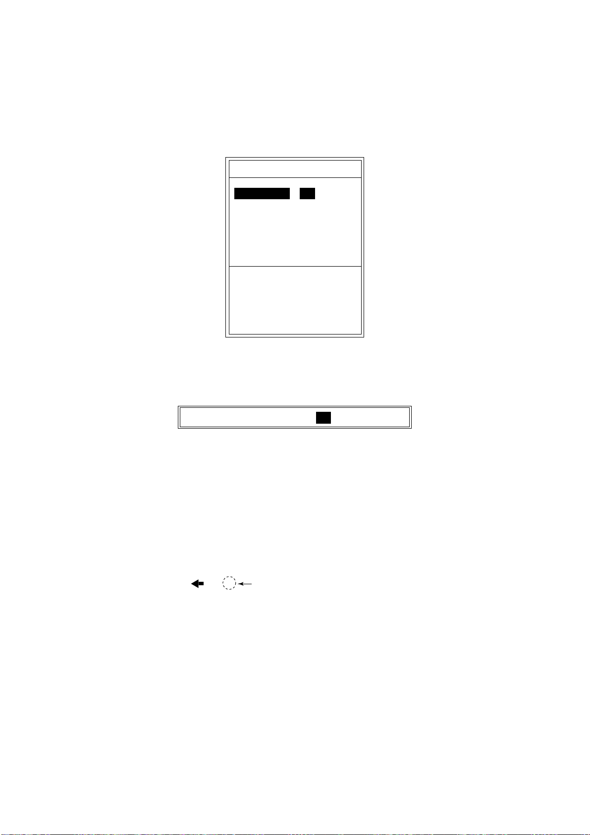
2. Press the [+] or [-] key to adjust the LCD brilliance (0 – 9).
([+] key: bright, [-] key: dark)
Note:Brilliance must be adjusted within five seconds after pressing the [BRILL] key or the
brill/panel dimmer window will be erased.
3. Press the [!] or ["] key to adjust the key panel dimmer (0 – 4, 0: OFF, 4: Maximum).
Adjust the key pan e l brilliance within five seconds or the window w ill be erased.
Note1: When turning off the power with brilliance set to minimum, since nothing will appear on
the display the next time the power is turned on. In this case, press the [BRILL] key several
times.
[] []
[][]
Brill/panel dimmer window
Note2: The brilliance of a commercial monitor cannot be adjusted with the [BRILL] key. Use the
associated control on the monitor.
1-3
Page 14
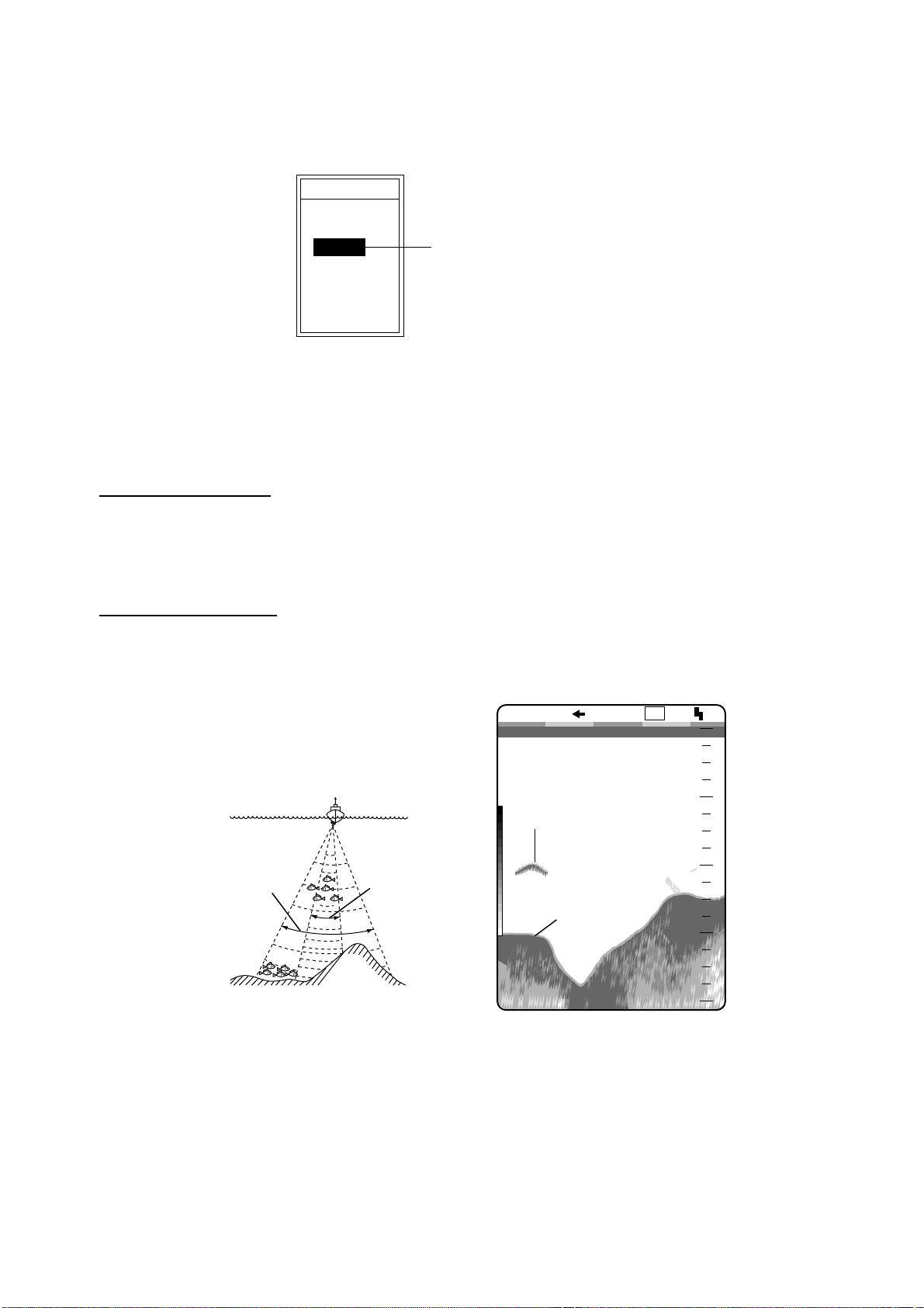
1.4 Presentation Mode
Seven presentation modes are available with the [MODE] switch.
MODE
LF-ZOOM
LF
DUAL
HF
HF-ZOOM
USER-1
USER-2
Display mode window
Single picture (low frequency or high frequency)
Low frequency (LF)
The lower the frequency of the ultrasonic pulse the wider the detection area. Thus, the low
frequency is suitable for general search and judging bottom condition.
Currentry selected mode
shown in reverce video
High frequency (HF)
The higher the frequency of the ultrasonic pulse the better the resolution. Therefore, the high
frequency pulse is useful for detailed observation of fish echoes.
LF
0.0
0
0
20
40
60
80
Low
frequency
Detection Area
High
frequency
Fish school
Bottom
49.6
Single Picture
1/1
ft
1-4
Comparison of detection ranges, sample single picture (low frequency)
Page 15
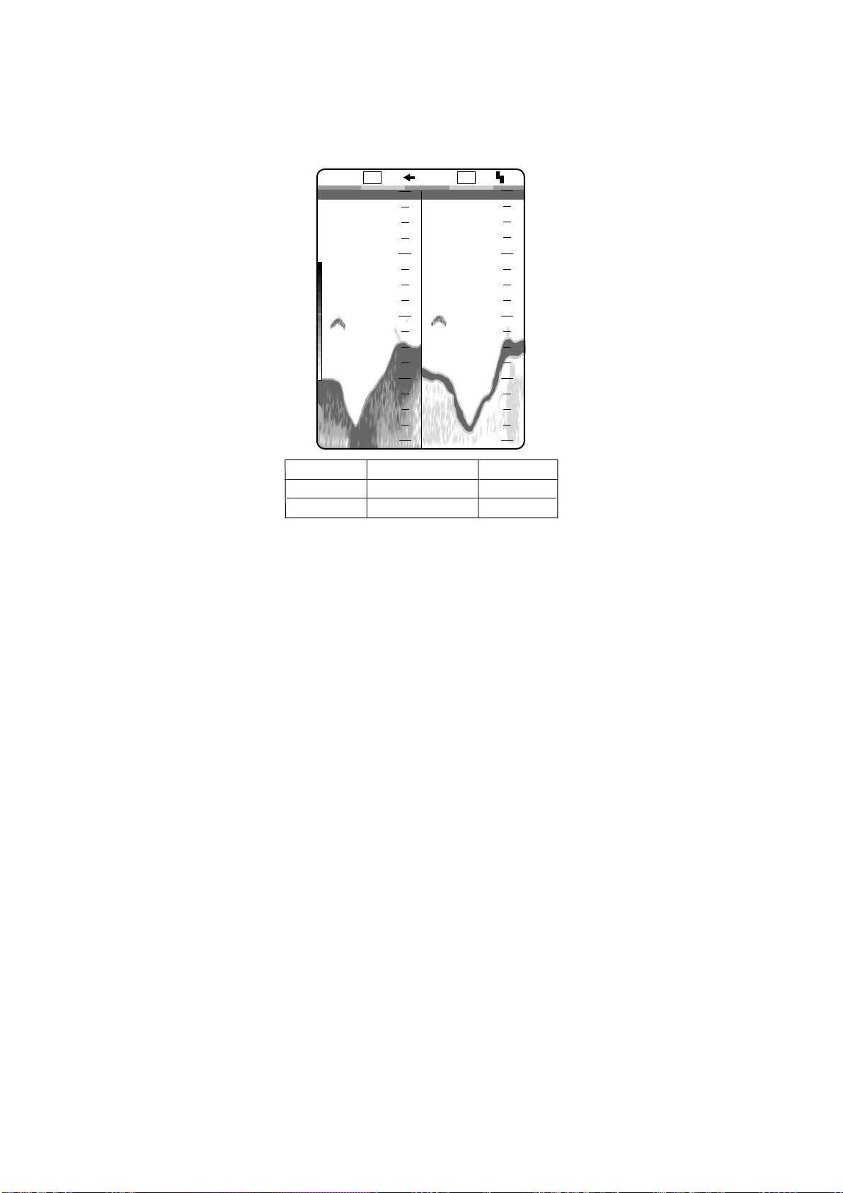
Dual
Provides the low frequency picture on the left 1/2 of the screen; the high frequency on the right
1/2.
1/1
LF
0
Low
frequency
20
HF
0.0
High
frequency
20
0
0
49.6
Frequency
Low
High
Dual frequency display
40
60
ft
80
Beamwidth
wide
Narrow
40
60
80
Echo trail
Long
Short
1-5
Page 16
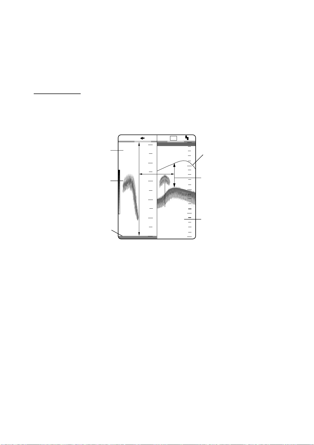
ZOOM
The “single picture” (high or low frequency) appears on the right 1/2 of the screen and t he zoom
picture on the left 1/2. The zoom picture may be selected among BOTTO M LOCK, BOTTOM
ZOOM, MARKER ZOOM, DISCRIM (discrimination) 1/2 and DISCRIM (discrimination) 1/3. The
default zoom picture is BOTTOM LOCK. You can select through the menu. See page 2-3.
BOTTOM LOCK
The bottom lock display shows the area between the zoom marker and the bottom as a straight
line to distinguish it from fish near the bottom, and thus it is useful for discriminating fish near
the bottom.
Bottom lock display
Zoomed fish school
Bottom as a straight line
1/1
5
4
3
2
1
21.7
ft
0
Bottom lock display
LF
Fish
school
10
20
30
40
0
0
0
Zoom marker
This area zoomed
and displayed on left
1/2 of screen.
Single frequency display
1-6
Page 17
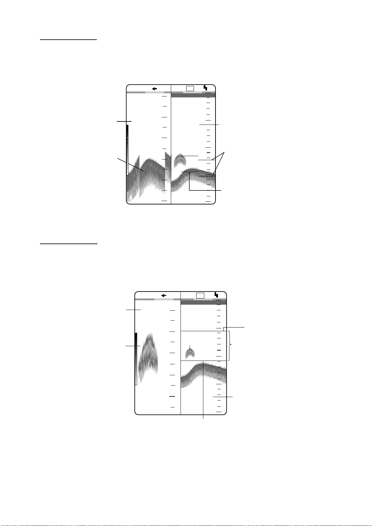
BOTTOM ZOOM
The bottom zoom display shows the zoomed bottom (automatically tracked) on the left 1/2 of
the screen. When the bottom depth increases, the display shifts to keep the bottom echo at the
lower part of the scre en.
Bottom zoom
1/1
24
26
LF
10
0
0
0
Single frequency display
display
28
Bottom
29.8
20
30
32
ft
34
30
40
Zoom marker (current)
Zoom marker (past)
Bottom zoom display
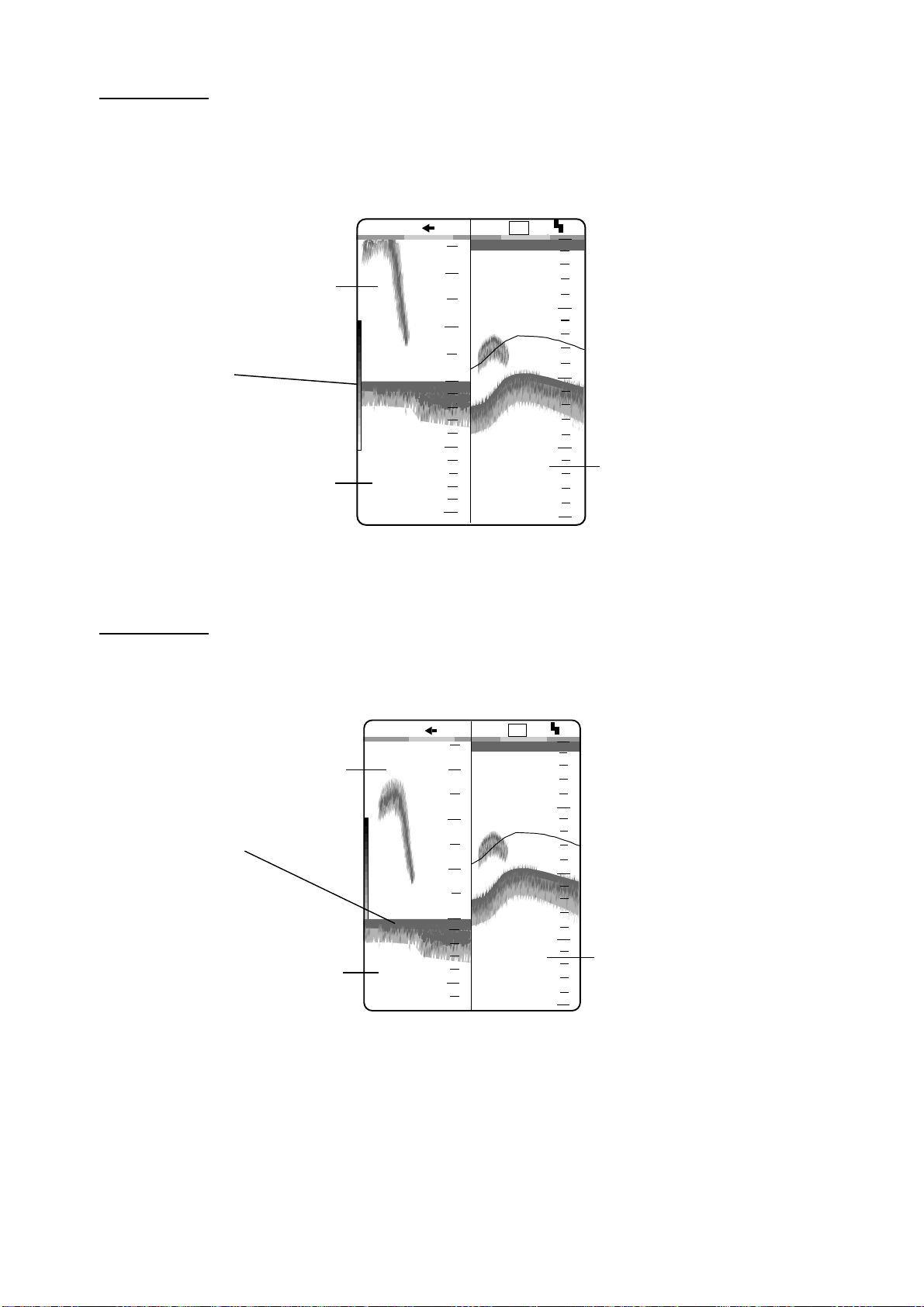
MARKER ZOOM
The marker zoom display expands the area selected with the VRM on the normal picture to full
vertical size of the screen on the left-half window. This mode is useful for observing specific fish
school.
Marker zoom
display
Zoomed fish school
1/1
12
14
16
18
20
25.0
ft
Marker zoom display
LF
11.5
Fish school
Zoom marker
10
20
30
40
0
0
0
VRM (Green)
This area is zoomed.
Single frequency display
1-7
Page 18
DISCRIM 1/2
The discrim(ination) 1/2 screen shows the single picture on the right 1/2 of the screen and the
bottom lock display and discriminator display occupy the left 1/2 of the screen. The discriminat or
display shows the bottom as a straight line, which is useful for determining bottom hardness.
Bottom lock display
Bottom trail
1/1
2
1
0
LF
10
20
0
0
0
Long tail=Hard bottom
Short tail=Soft bottom
10
30
Single frequency display
Bottom discrimination
display
21.5
ft
20
40
Discrim 1/2 display
DISCRIM 1/3
This display is similar to the DISCRIM 1/2 display except the bottom discriminator display
occupies only 1/3 of the left 1/2 of the screen as below.
1/1
Bottom zoom
3
display
2
Bottom trail
1
Long tail=Hard bottom
Short tail=Soft bottom
Bottom discrimination
display
21.5
0
10
ft
Discrim 1/3 display
LF
0
10
20
30
40
0
0
Single frequency display
1-8
Page 19
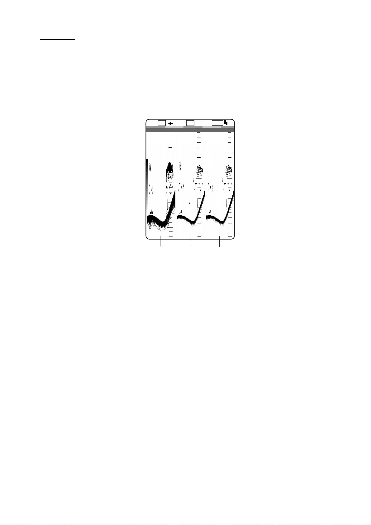
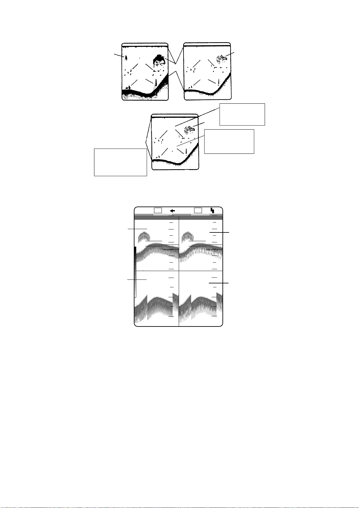
USER 1, 2
The display set at the user 1 (user 2) menu appears. Default setting is as follows.
USER 1: Vertical split three screens (LF + HF + MIX)
USER 2: Vertical and horizontal split four screens (LF + HF + LF bottom lock +HF bottom lock
displays)
This setting may be changed through the menu. For further details see page 2-11.
*Mix
LF
0
10
20
30
40
24.8
Low
frequency
User 1 display
HF
1/1
10
20
30
ft
40
High
frequency
0
MIX
0
10
20
30
40
Mix
display*
0
This mode compares echo intensity between low and high frequencies, and displays echoes
from tiny fish in discriminative colors. This is done by utilizing the fact that tiny fish return a
stronger echo against a high frequency rather than a low frequency. This is done as below.
1. If a high frequency echo is stronger than the corresponding echo on the low frequency, the
high frequency echo is displayed.
2. If the low frequency echo is stronger than or equal to the high frequency echo, it is less
likely to be a tiny fish and therefore is displayed in blue.
3. If the echoes on both frequencies have the intensity corresponding to reddish brown or red,
they are displayed in reddish brown or red: this is necessary to display the zero line and
bottom in reddish brown or red.
In other words, the echoes displayed in orange thru light-blue may be considered to be tiny fish
such as whitebait.
1-9
Page 20
Low frequency
High frequency
Blue
GRN
RED
Reddish-brown
Displayed in reddishbrown since high
freq. echoes are
red or reddish brown.
How the mix display works
R-BRN
+
Descriminator
YEL
BLU
LF
1/1
0
YEL
ORG
Blue
Displayed in blue
since high freq.
echo is weaker.
HF
0
0.0
Green
These echoes
are likely to be
small fish.
0
Low frequency display
Bottom zoom
display (LF)
23.6
10
20
30
40
21
22
23
ft
User 2 display
10
20
30
40
21
22
23
High frequency display
Bottom zoom
display (HF)
1-10
Page 21
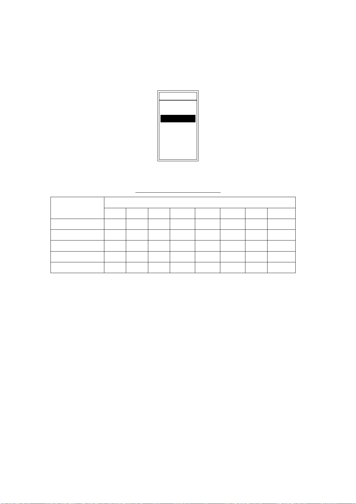
1.5 Selecting Basic Range
E
The basic range may be selected with the [RANGE] switch from the eight ranges listed below.
(The default unit of depth measurement is feet.) These eight ranges may be programmed as
desired. For details, see page 3-7.
RANG
30ft
60ft
120ft
250ft
500ft
1000ft
1600ft
3000ft
Range setting window (ex. feets)
Basic ranges (default setting)
Range Unit
1 2 3 4 5 6 7 8
Feet 30 60 120 250 500 1000 1600 3000
Meter 10 20 40 80 150 300 500 1000
Fathom 5 10 20 40 80 160 250 500
Hiro (Japanese) 6 12 25 50 100 200 300 600
Passi/Braza 6 12 25 50 100 200 300 600
Note1: This setting must be done within five seconds after rotating the [RANGE] switch once or
the range window will be erased.
Note2: Range for high and low frequencies can be set separately.
Note3: For how to select unit of depth measurement of depth, see page 3-3.
Range Switch Position
1-11
Page 22
1.6 Shifting the Basic Range
The [-] and [+] keys determine the start depth of the picture. Start depth (shift) is shown at the
top of the screen. The shift value setting is reflected on all other range by default. This function
is not available when AUTO SHIFT is ON in DISP menu.
Shift the start
depth to watch
shallow or deep.
picture
Principle of shift
SHIFT
10 ft
Shift window (screen center), shift indication (top right corner)
Note1: This operation must be done wit h in five seconds after pressing the [-] or [+] key or the
shift window will be erased.
Note2: The FCV-1200L/LM can automatically shift the display range to provide virtually
hands-free automatic operation. This can be done through the menu. For further details
see page 2-5.
Note3: You can set shift value independently for each range. See page 3-3.
10
1-12
Page 23
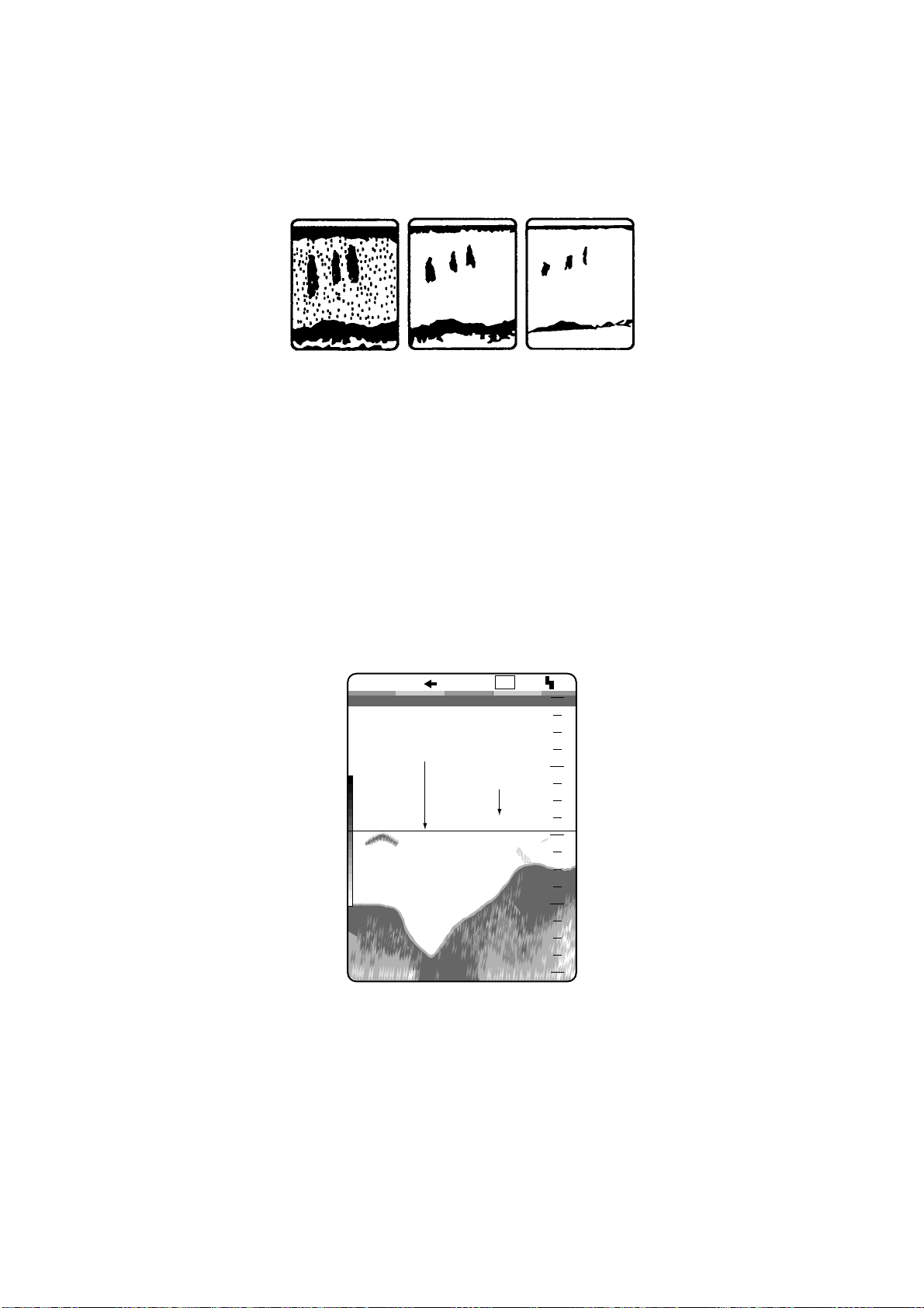
1.7 Adjusting Gain
The [GAIN] control adjusts the sensitivity of the receiver. Adjust it so excessive noise just
disappears from the screen.
Gain too high Gain proper
Gain too low
Examples of proper and improper gain levels
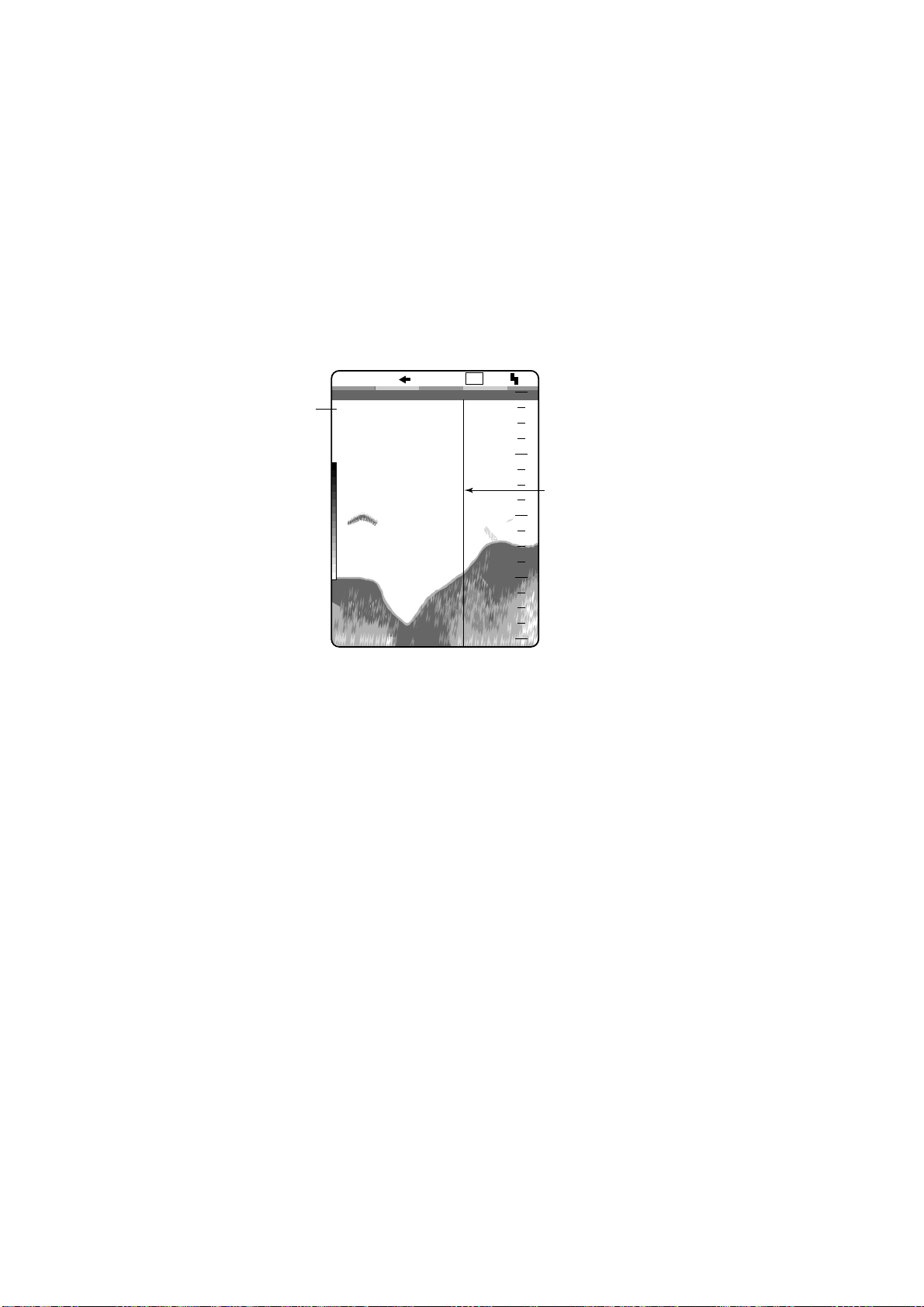
1.8 Measuring Depth
Use [!] or ["] key to place the VRM on the object to measure depth. Depth is digitally
displayed above the VRM.
Note: This operation is not available when the white marker window appears (by pressing the
[!] or ["] key). Select VRM at MARKER SELECT in DISP menu to use the VRM.
1/1
VRM (Green)
Depth to VRM
LF
0.0
0
0
20
39.8
40
60
49.6
ft
80
How to use the VRM
1-13
Page 24
1.9 Marker Line
The [MARKER/TLL] key inscribes a vertical line when pressed. It may be used to denote a fish
school or other important echo.
At the same moment the key is pressed latitude and longitude position may be output to
connected navigation plotter and marked on its screen. (This feature requires a navigation
plotter.) For further details see TLL OUTPUT on page 3-16.
Elapsed time from the moment that the [MARKER/TLL] key is pressed may be displayed at the
upper-left corner of the screen. For details, see page 2-5.
LF
0.0
0
0
Elapsed time from
when the
1/1
0H00M
[MARKER/TLL] key
is pressed.
20
Marker line
40
Shown in second color
from top of color bar in
16-color display; the top
color of color bar in 8-color
49.6
60
ft
80
display.
Marker/TLL key function
1-14
Page 25
1.10 Adjusting Clutter
When blue dots appear over the entire screen (mainly caused by dirty wat er ) , use the clutter
function to eliminate them.
1. Rotate the [FUNCTION] switch to select CLUTTER.
The clutter menu appears.
CLUTTER
HF•CLUTTER : 4 (0 7)
HF•CURVE : STD
LF•CLUTTER : 4 (0 7)
LF•CURVE : STD
Color changes
depending on
clutter level.
LOW HIGH
Change echo color
assignment.
[-/+]: Change setting
[EXIT (knob)]: Exit
Clutter menu
• For dual display → Go to step 2.
• For other modes → Go to step 3.
2. Press the [!] or ["] key to select HF CURVE or LF CURVE as appropriate.
3. Press the [-] or [+] key to open the clutter curve selection window (default: STD).
LINEAR CUSTOM
STD
Clutter curve selection window
STD: The higher the clutter level the smaller weak echoes are displayed. (default set t in g)
LINEAR: The high er t he clutter level the smaller all echoes are displayed.
CUSTOM: Applies the user clutter settings to the clutter menu.
4. Press the [!] or ["] key to close the window.
5. Press the [!] or ["] to select HF CLUTTER or LF CLUTTER as appropriate.
6. Press the [-] or [+] key to set clutter rejection level. (0-7, 0 turns clutter rejector off.)
1-15
Page 26
4
Clutter setting window
7. Rotate the [FUNCTION] switch fully counterclockwise to select EXIT.
Note: To use the user clutter setting menu setting is reflected on this function, select CUSTOM
at step 3.
1.11 Adjusting TVG
The TVG compensates for propagation loss of sound, so that the echoes from the same size
fish schools are displayed in the same color. Avoid excessive TVG ; weak echoes may not be
displayed. The TVG is also useful for reducing surface noise.
0 ft
100
How TVG works
1. Rotate the [FUNCTION] switch to select TVG.
The TVG menu appears.
TVG
HF·TVG LEV : 5 (0~10)
HF·TVG DIST: 600ft
LF·TVG LEV : 5 (0~10)
LF·TVG DIST : 600ft
0ft
0 ft
100
1-16
low
Adjust TVG effective
distance.
[-/+]: Change setting
[EXIT (knob)]: Exit
Gain high
This scale is
synchronized with the
distance value setting.
600
ft
TVG menu
Page 27

For dual display → Go to step 2.
•
• For other modes → Go to step 3.
Note: When only the picture of the external equipment is displayed, an error message appears
on the menu.
2. Press the [!] or ["] key to select HF TVG DIST or LF TVG DIST as appropriate.
3. Press the [-] or [+] key to set the TVG available distance.
The larger the setting, the lon ger t he range at which TVG works. The scale on the menu
synchronizes with the rate sett ing.
4. Press the [!] or ["] key to close the window.
5. When surface noise appears in the range shallower than the setting range, press the [!]
key to select HF TVG LEV(EL) or LF TVG LEV(EL) as appropriate.
6. Press the [-] or [+] key to set the TVG level in the setting window (range: 0-10).
The higher the TVG level, the less the gain near distance.
5
TVG level setting window
7. Rotate the [FUNCTION] switch fully counterclockwise to select EXIT.
1-17
Page 28
1.12 Eliminating Weak Echoes
Dirty water or reflections from plankton may be painted on the display in green or light-blue.
These weak echoes may be erased with the signal level function.
1. Rotate the [FUNCTIO N] switch to select SIG LEVEL.
The SIGNAL LEVEL menu appears.
SIGNAL LEVEL
SIGNAL LEV : OFF
Echo colors
disappear from
weakest to
OFF
current
strongest.
Eliminate low
intensity echoes.
[-/+]: Change setting
[EXIT (knob)]: Exit
Signal level menu
2. Press the [-] or [+] key to select the setting desired.
987654321OFF
Signal level setting window (For 16 colors)
Every pressing of the [+] key delet es echoes from weakest to strongest in ascending or der.
For eight colors, the setting window shows OFF , 1 t o 4.
3. Rotate the [FUNCTION] switch fu lly counterclockwise to select EXIT.
1-18
Page 29
1.13 Picture Advance Speed
The ADVANCE/A-SCOPE function selects picture advance speed.
1. Rotate the [FUNCTION] switch to select ADVANCE/A-SCOPE.
The PIC ADVNC/A-SCOPE menu appears.
PIC ADVNC/A-SCOPE
PIC ADVNC : 1/1
A-SCOPE : OFF
For picture advance
and A-SCOPE setting.
[-/+]: Change setting
[EXIT (knob)]: Exit
PIC ADVNC/A-SCOPE menu
2. Press the [-] or [+] key to select the speed desired.
1/16STOP 1/8 1/4 1/2 1/1 2/1 3/1 4/1
Picture advance speed setting window
The fractions in the window mea n t he number of vertical scan lines produced per trans missi on.
For example, “1/2” means a vert ical scan line is produced every two transmissions. These
fractions also appear at the top of the screen for your reference.
When selecting an adv ance speed, keep in mind that a fast advance speed will expand the size
of a fish school horizontally and a slow speed will contract it. The current spe ed appears at the
top of the display.
1/1 S
"S" means picture advance
speed is synchronized with
ship's speed.
See the next page.
Speed indication
3. Rotate the [FUNCTION] switch fu lly counterclockwise to select EXIT.
1-19
Page 30

Ship’s speed dependent mode
With speed data provided by a speed log, current indicator or navigation equipment, the display
advance speed may be set according to ship’s speed, the ship’s speed dependent mode. As
shown in the figure below the horizontal scale of the display is not influenced by the change of
ship’s speed, thus the speed-dependent picture advance permits j udgement of fish school size
and abundance at any speed. The picture advance speed indication is suffixed with an “S” when
the ship’s speed dependent mode is active. For exam ple, “1/1S.” For how to enable the ship’s
speed dependent mode see page 2-9. T his funct ion is available with ship’s speed of 2-20 kt.
Fish school is shrunk at high
ship's speed; expanded at
low ship's speed.
Same size
fish schools
Speed
FULL SPEED HALF SPEED
Actual Movement
How the ship’s speed dependent mode works
Normal Mode
Fish schools are shown
same size regardless of
ship's speed.
Ship's Speed Dependent Mode
1-20
Page 31

1.14 A-Scope Display
The A-scope picture displays echoes at each transmission with amplitudes and colors
proportional to their intensities on the right 1/4 of the screen. This feature is useful for close
observation of small fish and fish near the bottom,.
Note: For the dual mode display and vertical split screen, the A-scope display is available of the
high frequency only. In case of the horizontal split screen, high and low frequency A-scope
displays appear.
1. Rotate the [FUNCTION] switch to select ADVANCE/A-SCOPE.
The PIC ADVNC/A-SCOPE menu appears.
2. Press the ["] key to select A-SCOPE.
3. Press the [+] key to select ON in the setting window.
OFF ON
A- scope select ion window
4. Rotate the [FUNCTION] key to select EXIT.
To turn off the A-scope display , press the [-] key to select OFF at step 3 in this procedure.
LF
Single
frequency
49.6
ft
1/1
0
20
40
60
80
0
0.0
A-scope Display
No responce
Weak echo (fish)
Strong echo (bottom)
A-scope display
1-21
Page 32

1.15 Suppressing Interference
Interference from other acoustic equipment operating nearby or other electronic equipment on
your boat may show itself on the display as shown in t he figure below. You may suppress these
types of interference with the noise limiter.
Interference from
other sounder
Interference
1. Rotate the [FUNCTION] key to select NL.
The NOISE LIMITER menu appears.
NOISE LIMITER
HF·FREQ ADJ : +0.0%
-10
HF·NOISE LIM: OFF
LF·FREQ ADJ : +0.0%
-10
LF·NOISE LIM : OFF
1. Shift frequencies to
reject interference.
2. Use LF/HF·NOISE LIM
in case interference
hasn't been rejected.
[-/+]: Change setting
[EXIT (knob)]: Exit
0
0
+10
+10
Electrical interference
The inverted solid
triangle shifts with
operation of [-] or
[+] key.
NL menu
• For the dual display → Go to step 2.
• For other modes → Go to step 3.
Note: When only the picture from external equipment is displayed, an error message appears
on the menu.
1-22
Page 33

2. Press the [!] or ["] to select HF•FREQ ADJ or LF•FREQ ADJ whichever is appropriate.
3. Press the [-] or [+] key to set appropriate value in the setting window so that interference
disappears. (The setting range is -10.0% to +10.0%, however the lowest setting available
for the 68 and 200 kHz transducers is -4.5%.)
To adjust interference supp ression level finely, go to step 4.
If the interference suppression is sufficient, go to step 7.
4. Press the [!] or ["] key to close the setting window.
5. Press the ["] key to select HF•NOISE LIM or LF•NOISE LIM whichever is appropriate.
6. Press the [-] or [+] key to select the noise rejection setting in the setting window.
N3 provides the highest le vel of interference suppression.
OFF N1
N2
N3
Signal level setting window
7. Rotate the [FUNCTION] switch to select EXIT.
Note: Turn the noise limiter off when no interference exists, otherwise weak echoes may be
missed.
1-23
Page 34

1.16 Adjusting the External Video Sounder Picture
The USER-1/USER-2 display can show the picture from external equipment, and you can adjust
the picture as below.
1. Display the picture of the external equipment. “EXT” appears at the top of the screen.
2. Rotate the [FUNCTION] switch to select GAIN-EXT.
The EXTERNAL (3 rd) ECHO menu appears.
EXTERNAL (3rd) ECHO
GAIN : 5.0 (0 10)
CLUTTER : 4 (0 7)
CURVE : STD
TVG : 5 (0 10)
STC : 0 (0 10)
NOISE LIM : OFF
GAIN ADJ : +0 ( 50)
TX PULSE : STD
MANUAL
+
: 0.2 msec
These settings only
appear when the
picture from external
equipment is
displayed.
Optimize external (3rd)
echo presentation.
[-/+]: Change setting
[EXIT (knob)]: Exit
EXTERNAL (3 rd) ECHO menu
3. Press the [!] or ["] to select the item to adjust.
4. Press the [-] or [+] key to adjust.
5. Press the [!] or ["] to close the window.
6. Rotate the [FUNCTION] switch fu lly counterclockwise to select EXIT.
Items
GAIN: Adjusts gain (0.0-10.0 ) CLU TTER: See page 1- 15,
CURVE: See page 1-15 T VG: See page 1-16
STC: See page 2-9 NOISE LIM: Same as NOISE LIMITER. See page 1-22
GAIN ADJ: See page 2-9 TX PULSE, MA N UAL: Se e page 2-1 0
1-24
Page 35

2. MENU OPERATION
2.1 Basic Menu Operation
The main menu, consisting of the DISP (display), ALM (alarm), TX/RX , USER-1/2 and SYSTEM
menus, contains various items which once preset do not require frequent adjustment.
1. Rotate the [FUNCTION] switch fully clockwise to select MENU.
The last-used menu among DISP, ALM, TX/RX, USER-1/2 and SYSTEM appears.
The illustration below sh ows the DISP menu.
Menu titles
Description for
selection.
DISP ALM TX/RX USER-1/2 SYSTEM
ZOOM MODE : BOTTOM LOCK
NO. OF COLORS : 16
HUE : STD
BACKGROUND : BLUE
WHITE LINE : OFF (OFF, 1~10)
DEPTH INFO : STD
BOTTOM SEARCH : AUTO
MARKER SELECT : VRM
AUTO SHIFT : OFF
DISPLAY DATA : TIMER
SCROLL TIME : OFF
SMOOTHING-1 :
SMOOTHING-2 : OFF
Menu for display setting.
[-/+]: Change set, [EXIT (knob)]: Exit
DISP menu
2. Press the [!] key to select menu title area.
(OFF,1~8)
3. Press the [+] or [-] key to select menu desired among DISP, ALM, TX/RX, USER-1/2 and
SYSTEM.
The menu selected is hig hlighted in the menu title area.
4. Press the [!] or ["] key to select item. For example, select NO. OF COLORS.
Menu help for the item selected ap pears at t he bottom of the screen.
5. Press the [-] or [+] key to display the setting window. The illustration below shows the
selection window for NO. OF COLORS.
8 16
Selection window (ex. NO. OF COLORS)
2-1
Page 36

cursor position in relation to the entire option range. This bar shifts with operation of [-] or [+] key.
Blue bar
CUSTOM STD HUE1 HUE2 HUE3 HUE4
The blue bar shows the current cursor position in
relation to the option range.
This bar shifts with operation of [-] or [+] key.
Selecting window (for item having several options, ex. HUE)
7. Rotate the [FUNCTION] switch fully counterclockwise to select EXIT.
The menu disappears.
2-2
Page 37

2.2 DISP Menu
DISP ALM TX/RX USER-1/2 SYSTEM
ZOOM MODE : BOTTOM LOCK
NO. OF COLORS : 16
HUE : STD
BACKGROUND : BLUE
WHITE LINE : OFF (OFF, 1~10)
DEPTH INFO : STD
BOTTOM SEARCH : AUTO
MARKER SELECT : VRM
AUTO SHIFT : OFF
DISPLAY DATA : TIMER
SCROLL TIME : OFF
SMOOTHING-1 :
SMOOTHING-2 : OFF
Menu for display setting.
[-/+]: Change set, [EXIT (knob)]: Exit
For picure advance speed: 2/1, 3/1, 4/1
For picture advance speed : 1/16, 1/8, 1/4, 1/2, 1/1
(OFF,1~8)
DISP menu
ZOOM MODE
Selects the zoom mode to show when the [MODE] switch selects ZOOM. Ref er to Chapter 1.
NO. OF COLORS
Selects eight color or sixteen-color presentation.
HUE
Selects desired picture color. USER displays the colors programmed by the user. (See chapter
3.) STD is the standard colors used on most FURUNO video sounders. HUE 1-7 provide other
picture color arrangements.
BACKGROUND
Selects background color to black, dark blue, blue, light-blue or white. Note that the background
color is fixed when the user color (in HUE above) is selected.
WHITE LINE
Changes the strongest signal color to white. The higher the setting, the wider the white line.
Generally, f ish schools on or close to the bottom are displayed on the screen as if they are small
rising of the bottoms. This feature can help discriminate bottom fish schools from the bottom.
2-3
Page 38

DEPTH INFO
Changes the size and position of the depth indication.
BOTTOM SEARCH
On the dual frequency display, select transducer which is to measure depth. AUTO, automatic;
LOW, low frequency, HIGH, high frequency.
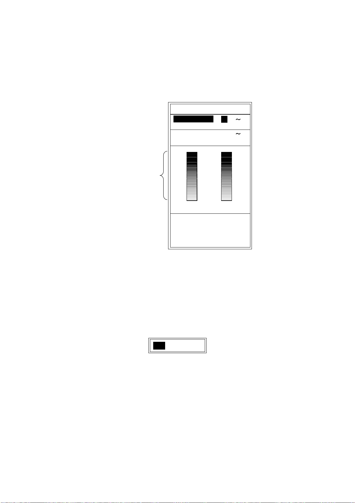
MARKER SELECT
Selects the marker function, VRM or WHITE MARKER.
VRM: Measures depth to an echo.
WHITE MARKER: The echo from a fish school or the bottom can be displayed in white.
(White marker operation)
1. After the selecting EXIT with the [FUNCTION] switch to close the menu, press the [!] or ["]
key to show the white marker setting window.
WHITE MARKER
Color bar
The color selected
by this red arrow
changes to white.
OFF
/ : Select color
to enhance.
White marker setting window
2. Press the [!] or ["] key to select the echo color which you want to emphasize.
The setting window disappears if there is no key operation within five seconds.
The color bar selected to display in white is displayed in white on the color bar.
Note:
Before changing from WHITE MARKER to VRM, you must select OFF in the white marker
setting window.
2-4
Page 39

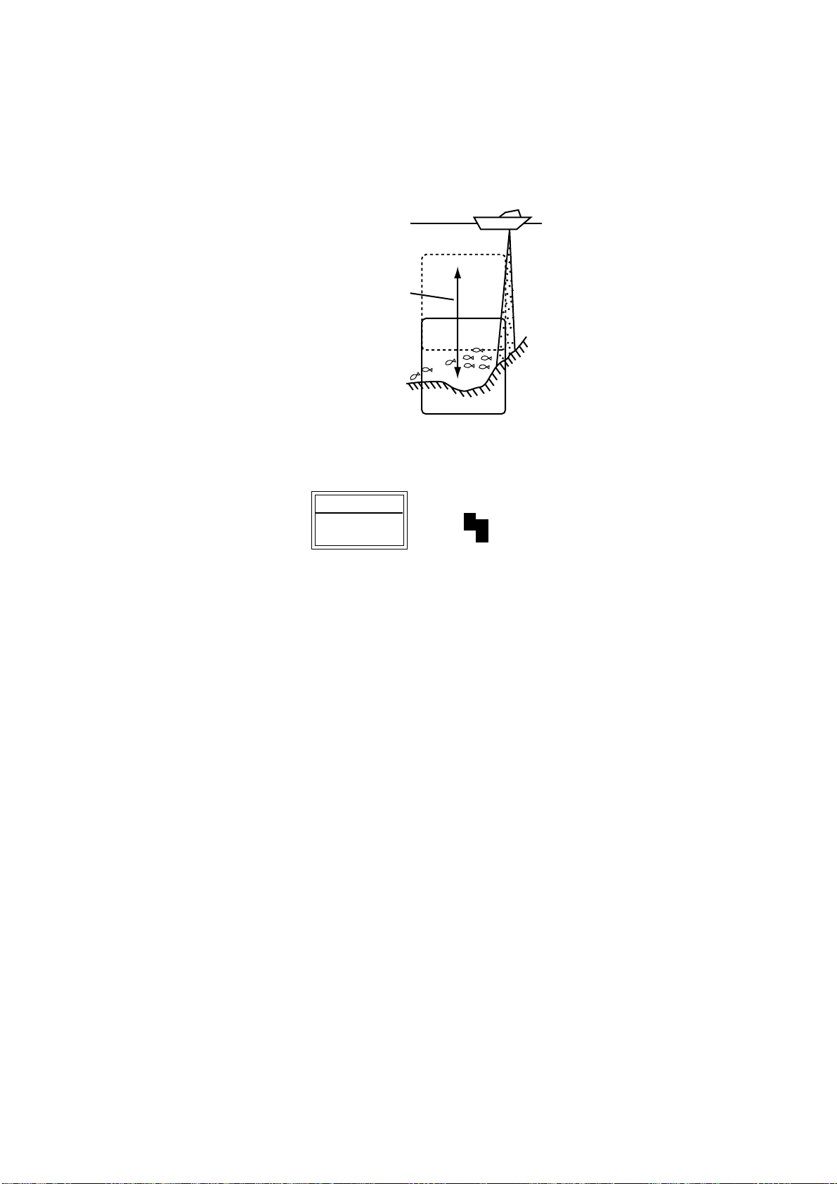
AUTO SHIFT
Selects manual or automatic depth shift. The automatic shift function automatically locates the
bottom trace on the lower half of the screen; the range window jumps up where the bottom trace
rises over the center of the screen and jumps down when it reaches the bottom of the screen.
AUTO appears at the top right corner of the screen when the auto shift function is on. Note that
the [+] and [-] key are inoperative when the automatic shift function is turned on,
1/2
3/4
3/4
Range changes automatically to
locate the bottom on the lower half
of screen.
The equipment shifts to a deeper
range when the bottom comes to
the lower edge of the depth scale.
Automatic shift concept
DISPLAY DATA
Selects the data to display at the left top corner of the screen among OFF, L/L*, TD*, TIMER
(Elapsed time from the moment when the [MARKER/TLL] key is pressed), GAIN**, R/B* (range
and bearing to the waypoint) and COURSE*.
*: Requires navigation device.
**: The gain setting shown on the display may not agree exactly with GAIN controller position.
When you change the gain setting and then return correctly, using of the setting shown on
the display is recommended.
SCROLL TIME
Turns the display scroll time on/off. Scroll time displays, at the screen bottom, the amount of
time a scan line stays on the screen as it passes from one side of the screen t o the other. Time
varies with the range and picture advance speed.
SMOOTHING-1
This setting can only be changed when the picture advance speed is set to 1/16, 1/8, 1/4, 1/2 or
1/1. (See page 1-19.) This function smoothes echo presentation. The higher the number, the
greater the smoothing. Ad j ust the setting when echoes appear “spotty.”
SMOOTHING-2
This setting can only be changed when the picture advance speed is set to 2/1, 3/1 or 4/1. (See
page 1-19.) This function smoothes echo pr esentation. Select ON when rough echoes appear.
2-5
Page 40

2.3 ALM Menu
Sets the alarms; BOTTOM, FISH and TEMP (temperature). To silence the alarm beep, press the
[-], [+], [!] or ["] key.
BOTTOM ALARM
When your ship comes in the area of the selected depth, the beep sounds and the indication
BTM flashes at the top right corner to draw your attention.
FISH ALARM
FISH ALARM: Fish echoes of yellow or stronger colors (default setting) trigger the alarm.
BTM-FISH ALARM: When fish echoes come in the area which you set above the bottom, the
beep sounds and the indication FISH flashes at the top right corner of the screen. (Available
mode: bottom lock, discrim 1/2, discrim 1/3)
TEMP ALARM
Selects temperature range which triggers temperature alarm. Alarm is activated (beep sounds
and the indication TEMP appears at the top right corner of the screen) when water temperature
is above (UP) or below (DOWN) the preset value. This function requires a water temperature
sensor.
2.3.1 Setting the alarm
1. Rotate the [FUNCTION] switch fully clockwise to select MENU.
2. Press the [!] key to select the menu title area.
3. Press the [-] or [+] key to select ALM to display the ALM menu.
2-6
Page 41

DISP ALM TX/RX USER-1/2 SYSTEM
BOTTOM ALARM : OFF
ALARM DEPTH : 0 ft
ALARM ZONE : 10 ft
FISH ALARM : OFF
ALARM DEPTH : 0 ft
ALARM ZONE : 10 ft
ALARM LEVEL : MID
TEMP ALARM : OFF
TEMP LIMIT : 65.0˚F(20~95)
ALARM ZONE : 1.0˚F
Menu for alarm setting.
[-/+]: Change set, [EXIT (knob)]: Exit
*: The setting is not available when ALARM
is OFF.
*
*
*
ALM (Alarm) menu
4. Press the [!] or ["] key to select the alarm which you want to set.
5. Press the [-] or [+] key to show the alarm setting window.
OFF ON
Bottom alarm
OFF FISH BTM-FISH
Fish alarm
OFF WITHIN RANGE OUT OF RANGE
Temp alarm
Alarm setting window
6. Press the [-] or [+] key to select the alarm type desired.
7. Press the ["] key twice to select ALARM DEPTH (TEMP LIMIT for temp alarm).
8. Press the [-] or [+] key to show the alarm setting window.
0 ft
Starting depth setting window (ex. Depth alarm)
9. For BOTTOM ALARM and FISH ALARM, press the [-] or [+] key to set the starting point of
alarm zone.
Alarm marker appears (Depth al arm: green, Fish alarm: white).
2-7
Page 42

BTM
Selected alarm
(flashing)
Alarm area
12.5
ft
Start line
Alarm marker
Bottom alarm (green): right side
Fish alarm (white): right side
Bottom-fish alarm (white): left side (vertical screen division)
right side (horizontal screen division)
Setting of alarm zone (ex. Bottom alarm)
10. Press the [] key to sele ct ALARM ZONE.
11. Press the [-] or [+] key to show the alarm zone setting window.
10 ft
Alarm zone setting window (ex. Bottom alarm)
12. Press the [-] or [+] key to set the alarm zone.
For depth alarm and temp alarm, go to step 16. To set the fish alarm, go to step 13.
13. Press the [] key to select ALARM LEV EL.
14. Press the [-] or [+] key to show the level setting window.
MIN MID MAX
Level setti ng window
15. Press the [-] or [+] key to set the alarm level.
MIN: Alarm triggered against light-blue or stronger fish echoes.
MID: Alarm triggered against yellow or stronger fish echoes.
MAX: Alarm triggered against red or stronger fish echoes.
16. Rotate the [FUNCTION] switch fully counterclockwise to select EXIT.
To cancel an alarm, select OFF at step 6.
2-8
Page 43

2.4 TX/RX Menu
DISP ALM TX/RX USER-1/2 SYSTEM
PRR LEVEL : (0~20,S)
<High Frequency>
STC :
GAIN ADJ : +
*1
*1
RX BAND : STD
TX PULSE : STD
PULSE LENGTH : 0.2msec (0.2~5.0)*2
<Low Frequency>
STC :
GAIN ADJ : +
RX BAND : STD
TX PULSE : STD
PULSE LENGTH : 0.2msec (0.2~5.0)*2
Menu for TX/RX setting.
[-/+]: Change set, [EXIT (knob)]: Exit
*1: FCV-1200L only
*2: The setting becomes available when
MANUAL is selected at TX PULSE.
(0~10)
(0~10)
TX/RX menu
PRR LEVEL
Changes pu lse repetition rate. Normally, the highest rate (20) is used. When in shallow waters
second reflection echoes may appear between surface and actual bottom echo. In this case
lower the PRR level.
The choice “S” means the ship’s speed dependent mode, where the PRR changes
automatically with ship’s speed. (Requires ship’s speed input.) For further information about the
ship’s speed dependent mode, see page 1-20.
STC (High and Low Frequencies)
Adjusts STC level for the high and low frequencies, and is useful for suppressing surface noise.
The setting range is 0-10; the higher the setting the greater the extent of suppression. Setting
10 suppresses noise up to about 5 m. Turn off the STC when there is no noise on the screen,
otherwise weak echoes may be missed.
GAIN ADJ (High and Low Frequencies)
Adjusts gain (range: -50 to +50) of transceiver unit selected. Adjust the setting when the GAIN
control cannot effectively adjust the gain.
2-9
Page 44

RX BAND (High and Low Frequencies)
Sets amplifier bandwidth of high and low frequency Rx amplifier.
When NARROW is selected, the noise suppression is greater however resolution is lower in
shallow water. Normally, set to STD. For more effective resolution, select WIDE.
TX PULSE (High and Low Frequencies)
Sets TX pulselength for high and low frequencies. The available choices are SHORT1,
SHORT2, STD, LONG, and MANUAL. Pulselength (without MANUAL) automatically changes
with range and shift.
PULSE LENGTH (High and Low Frequencies)
When selecting MANUAL on TX PULSE, this setting (setting range: 0.2 msec – 5.0 msec) is
active. The smaller digit, the greater the detection resolution; the larger digit, the longer the
detection range.
2-10
Page 45

2.5 USER-1/2 Menu
Sets screen division for the dual frequency picture. This setting can be selected with USER-1, 2
of the [FUNCTION] switch. Default settings are as below.
USER-1:
USER-2:
( [LF]+[HF] +[MIX])
([LF]ZM/NOR+[HF]ZM/NOR)
DISP ALM TX/RX USER-1/2 SYSTEM
<USER 1>
SCREEN LAYOUT
DISP MODE : [LF]+[HF]+[MIX]
ZOOM MODE : BOTTOM ZOOM *1
<USER
SCREEN LAYOUT:
DISP MODE :
ZOOM MODE : BOTTOM ZOOM
EXT DEVICE : ETR*2
DEFAULT SET : NO
Menu for user-preset mode setting.
[-/+]: Change set, [EXIT (knob)]: Exit
*1: The setting is available when Zm (Zoom)
is selected at the DISP MODE field.
*2: The setting is available when EX is
selected at the DISP MODE field.
2>
:
[LF]Zm/Nor+[HF]Zm/Nor
USER-1/2 menu
SCREEN LAYOUT
Selects the screen division layout among the following patterns.
2-11
Page 46

DISP MODE
Selects the picture to display in respective screen layout. See the Appendix 2 at the back of this
manual for detailed information.
[HF]:Normal
[LF]:Normal
[EX]:Normal*
[HF]:Zoom
[LF]:Zoom
[EX]:Zoom*
[MIX]:Normal
[HF]:Zm/Nor
[LF]:Zm/Nor
[EX]:Zm/Nor*
[LF]+[HF]
[EX]+[HF]*
[EX]+[LF]*
[LF]:Zm+[HF]:Zm
[HF]+[MIX]
[LF]+[MIX]
[H]sub+[HF]
[L]sub+[LF]
*: EXIF assy. (option) equipped for FCV-1200L,
INTERNAL selected at XDCR CONNECT
on the E/S DRAFT SETTING menu.
[LF]+[HF]:Zm/Nor
[LF]:Zm/Nor+[HF]
[EX]+[HF]:Zm/Nor*
[EX]+[LF]:Zm/Nor*
[EX]:Zm/Nor+[HF]*
[EX]:Zm/Nor+[LF]*
[EX]+[LF]+[HF]*
[MIX]+[LF]+[HF]
[LF]+[H]sub+[HF]
[L]sub+[LF]+[HF]
[LF]:Zm/Nor+[HF]:Zm/Nor
HF: high frequency LF: low frequency,
NOR: normal ZM: zoom,
MIX: mix Sub: gain for fish and seabed echoes is raised
EX: display of external transducer unit or telesounder
Gain (sub)
The [GAIN] control mainly adjusts the bottom echo. When selecting the sub (sub gain), the
[GAIN] control adjusts the fish and bottom echoes. At the sub gain mode, press the [-] or [+] key
to show the sub gain setting window.
GAIN (SUB)
1 . 3
Sub gain setting window
Press the [-] or [+] key to select the setting value (0.0-10.0) within five seconds.
ZOOM MODE
Selects the zoom mode to use.
2-12
Page 47

EXT DEVICE
Selects the equipment to use for EX in use mode EX of SCREEN LAYOUT. “EXT” appears at the
top of the screen.
ETR: External Transceiver Unit
TS/OTHER: telesounder, external echo sounder, sonar, picture recorder.
Note:
When selecting
should be connected to the EXT_H port. The EXT_L port signal cannot be displayed on
those screen layouts.
or screen, the above equipment (low frequency echo)
DEFAULT SET
Restores default settings of the user-1/2 menus. Select YES to restore default settings. Three
beeps sounds while default settings are being restored.
2-13
Page 48

This page is intentionally left blank .
Page 49

3. SYSTEM MENU
3.1 SYSTEM Menu Operation
1. Rotate the [FUNCTION] switch fully clockwise to select MENU.
2. Press the [!] key to select the menu title area.
3. Press the [+] key to select SYSTEM to show the system menu.
DISP ALM TX/RX USER-1/2 SYSTEM
SYSTEM SETTING
ES / DRAFT SETTING
RANGE SETTING
TEMP SETTING
NET SONDE SETTING
USER COLOR SETTING
USER CLUTTER SETTING
NAV DATA SETTING
TARGET ECHO
TEST MODE
DEFAULT SETTING
Menu for system setting.
[+]: Go to setting [EXIT (knob)]: Exit
System menu
4. Press the [!] or ["] key to select the item which you want to set.
5. Press the [+] key to show the sub menu.
6. Rotate the [FUNCTION] switch fully counterclockwise to select EXIT.
The system menu disappears.
3-1
Page 50

3.2 SYSTEM SETTING Menu
This menu mainly sets picture layout parameters.
DISP ALM TX/RX USER-1/2 SYSTEM
SYSTEM SETTING
LANGUAGE : ENGLISH
PICT ADV DIR : LEFT
DEPTH SCALE : RIGHT
DISP DIVISION :
ZOOM MARKER: ON
FREE SHIFT : OFF
ECHO STRETCH : OFF
DEPTH UNIT : ft
SPEED UNIT : kt
TEMP UNIT : ˚F
BOTTOM LEVEL :+0 (-40 ~ +0)
Select system language.
[-/+]: Change set, [EXIT (knob)]: Exit
SYSTEM SETTING menu
LANGUAGE
Selects the language, ENGLISH or JAPANESE. After making selection, rotate the [FUNCTION]
switch to select EXIT. This permits switching of language.
PICT ADV DIR
Selects picture advance direction to left, right or left/right which advances the picture in both
right and left directions from the screen center.
DEPTH SCALE
Selects where to position the depth scale; right, center or off .
DISP DIVISION
Sets screen division for the dual picture. vertically divides the screen; horizontally
divides the screen.
3-2
Page 51

ZOOM MARKER
Turns zoom marker on/off.
FREE SHIFT
Set shift value independ ently for each range (ON) or commonly for all range (OFF).
ECHO STRETCH
Displays the strong echoes long though the pulse length setting is short. It is useful for
distinguishing individual fish (e.x. squid) in plankton.
DEPTH UNIT
Selects unit of depth measurement; meters, feet, fathoms, hiro (Japanese), passi/braza.
SPEED UNIT
Selects unit of ship’s speed; kt, km/h, sm/h.
TEMP UNIT
Sets unit of water temperature measurement; Celsius or Fahrenheit.
BOTTOM LEVEL
When seabed depth readout is unstable,
use this feature to stabilize it. The
setting range is -40 to 0, and the default
setting is 0.
If this setting value is too small, fish
echo m ay be regarded as bottom w hich
causes unstable depth readout.
Bottom lock display
Set the bottom
search so that this
line disappears.
1/1
5
4
3
2
1
0
Seabed
LF
10
20
30
40
0
0
0
3-3
Page 52

3.3 ES/DRAFT SETTING Menu
This menu sets up the transducer and ship’s draft.
DISP ALM TX/RX USER-1/2 SYSTEM
ES/DRAFT SETTING
<High Frequency>
XDCR CONNECT : INTERNAL
TX POWER : MAX
*
DRAFT : +0.0 ft (-15 +90)
FREQ CHOICE : 75 kHz
<Low Frequency>
XDCR CONNECT :INTERNAL
TX POWER : MAX
*
DRAFT : +0.0 ft (-15 +90)
FREQ CHOICE : 22 kHz
E/S SIG OUT : OFF
KP SETTING : INTERNAL
Select transducer connected.
[-/+]: Change set, [EXIT (knob)]: Exit
*: FCV-1200L only
ES/DRAFT SETTING menu
XDCR CONNECT (High and Low Frequencies)
Sets the video sounder to be used for the high and low fr eq uencies, as follows.
INTERNAL: Use the internal video sounder signal (FCV-1200L only).
ETR: Use the video sounder signal from the external Transceiver unit (FCV-1200LM and
FCV-1200L with optional EXIF assy. only).
TS/OTHER: Use the video sounder signal from the external telesounder, video sounder or
sonar (FCV-1200LM and FCV-1200L with optional EXIF assy. only).
Note: Choose INTERNAL when selecting LF, HF or LF/HF at the ES SIG OUT described on the
next page.
TX POWER (High and Low Frequencies)
Reduces the power output on high and low frequency (FCV-1200L only). <P/R> appears at the
bottom of the screen when MIN is selected. When interference from near another shipborne
transducer occurs, set this item appropriately. (MAX →1/2→ 1/4→ 1/8→ 1/16 →MIN)
3-4
Page 53

DRAFT
Sets the ship’s draft, to show the depth between the sea surface and the bottom (rather than
from transducer to bottom). When the picture recorder MT-12 is used to replay the recording
data, set the draft to –2.0 ft.
FREQ CHOICE
You can select the transmitting frequencies for the following transducers. Select the frequency to
use on this menu.
This function is useful when there is interference from other vessel, or when targeting certain fish
species.
50kHz/75kHz transducer
Using the following transducers with 75 kHz provides high resolution.
•
50B-6
•
50/200-1T (50kHz)
•
50/200-1ST(50 kHz)
•
50B-9
•
50B12
88 kHz/22 kHz transducer
Using the following transducer with 22 kHz frequency enables long range detection, a
characteristic of low frequency.
•
88B-10
Note:
When the above transducers are used with 75 kHz or 22 kHz, the transmission line may
be longer slightly.
3-5
Page 54

E/S SIG OUT
Outputs selected video sounder signal to external equipment. Default setting is OFF (no output).
In the following cases, the optional EXIF assy. is required for FCV-1200L.
•
When telesounder is connected on sister ship.
•
When recording video sounder signal by picture recorder.
•
When FCV-1200L outputs video sounder signal to other color video sounder.
LF: Outputs the low frequency signal.
HF: Outputs the high frequency signal.
LF/HF: Outputs both the high and low frequency signals.
Note:
When selecting LF, HF, or LF/HF, select INTERNAL at XDCR CONNECT.
Equipment connected XDCR CONNECT E/S SIG OUT Remarks
External
Telesounder on sister ship INTERNAL LF, HF, LF/HF Not available on FCV-
Telesounder on master
ship
Record by picture recorder INTERNAL LF, HF, LF/HF Not available on FCV-
Play back by picture
recorder
Outputs to other E/S INTERNAL LF, HF, LF/HF Not available on FCV-
transceiver unit
ETR
TS/OTHER
TS/OTHER
-
1200LM
-
1200LM
-
1200LM
KP SETTING
Synchronizes transmission with other echo sounders. Select EXTERNAL to synchronize
transmission.
3-6
Page 55

3.4 RANGE SETTING Menu
This menu allows the user to preset the range selected with the [RANGE] control.
DISP ALM TX/RX USER-1/2 SYSTEM
RANGE SETTING
RANGE1 : 30 ft (16 6000)
RANGE2 : 60 ft
RANGE3 : 120 ft
RANGE4 : 250 ft
RANGE5 : 500 ft
RANGE6 : 1000 ft
RANGE7 : 1600 ft
RANGE8 : 3000 ft
M/Z RANGE : 16 ft (16 600)
B/L RANGE : 16 ft
SPLIT RANGE: OFF
Set preset range scales.
[-/+]: Change set, [EXIT (knob)]: Exit
RANGE SETTING Menu
Note:
Hiro is the Japanese unit of depth measurement.
RANGE1-RANGE8
Presets basic ranges for the [RANGE] switch. (5-2000 m, 16-6000 ft, 2-1200 fa, 4-1600 hiro, 3-
1200 P/B)
M/Z RANGE
Sets display range of marker zoom and bottom zoom pictures. (5-200 m, 16-600 ft, 2-120 fa,
4-160 hiro, 3-120 P/B)
Note:
For the vertical split screen, halve the above values.
B/L RANGE
Sets display range of bottom-lock, discrim-1/2, discrim-1/3 picture. (5-200 m, 16-600 ft, 2-120 fa,
4-160 hiro, 3-120 P/B)
Note:
For the vertical split screen, halve the above values.
3-7
Page 56

SPLIT RANGE
Select ON to set range for low frequency and high frequency individually.
1. Rotate the [RANGE] switch to show RANGE (LF or HF) window.
RANGE [LF]
30 ft
60 ft
120 ft
250 ft
500 ft
1000 ft
1600 ft
3000 ft
Switch [LF] and [HF] by
pressing the [RANGE]
switch.
RANGE [HF]
30 ft
60 ft
120 ft
250 ft
500 ft
1000 ft
1600 ft
3000 ft
Range window
2. Press the [RANGE] switch within five seconds to display the RANGE (LF) window or
RANGE (HF) window whichever desired.
3. Rotate the [RANGE] switch to select the range desired.
3-8
Page 57

3.5 TEMP SETTING Menu
This menu sets up water temperature sensor.
DISP ALM TX/RX USER-1/2 SYSTEM
TEMP SETTING
TEMP INPUT : SENSOR
TEMP ADJUST : +0.0 F(-20 +20)
TEMP READOUT : ON
TEMP GRAPH : OFF
TEMP COLOR : STD
Select temperature sensor.
[-/+]: Change set, [EXIT (knob)]: Exit
TEMP SETTING menu
TEMP INPUT
Selects source of water temperature data; net sonde, sensor, NMEA or CIF.
TEMP ADJUST
Offsets water temperature indication to improve accuracy. Effective only for net sonde and water
temperature sensor. (-20.0 to +20.0°F in 0.1 step)
TEMP READOUT
Turns on/off water temperature indication.
TEMP GRAPH
Turns on/off temperature graph and selects graph scale.
OFF: No water temperature graph NARROW: Graduation every 2°
STD: Graduation every 2.5° (default setting) EXPAND: Graduation every 5.0°
TEMP COLOR
Selects the color of the temperature graph (standard, white, red, black, yellow).
Note: Standard means the fifth color from the bottom of the color bar, including background
color in 16-color display; third color in 8-color display. Yellow means tenth (8-color display: sixth)
color from the bottom of the color bar.
3-9
Page 58

3.6 NET SONDE SETTING Menu
This menu sets up the Net Sonde.
DISP ALM TX/RX USER-1/2 SYSTEM
NET SONDE SETTING
SONDE MARK : OFF
COLOR :1
WIDTH : 2
SONDE GRAPH : OFF
GRAPH MODE :SURFACE
GRAPH WIDTH:1/4
GRAPH RESET: NO
Indication of sonde mark.
[-/+]: Change set, [EXIT (knob)]: Exit
NET SONDE SETTING menu
SONDE MARK
Selects where to display the sonde mark; HIGH frequency picture, LOW frequency picture or
OFF.
1/1
LF
0.0
0
0
20
40
Sonde mark
60
COLOR
Selects number of colors to display net sonde mark; 1 (14 level color), 2 (12 level color) or 3 (10
level color).
WIDTH
Selects the width of sonde mark; 2 dot s, 3 dots, 4 dots or 5 dots.
3-10
Page 59

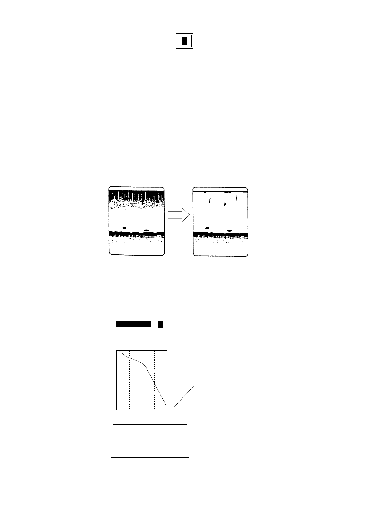
SONDE GRAPH
Turns on/off the net sonde water temperature graph.
Net sonde water temperature graph (at the left-hand side of display)
GRAPH MODE
Horizontal lines
show depth.
10 15 20
0510
Water temperature
graph
Selects the display starting position of the net sonde water temperature graph. SURFACE is the
first-water temperature (surface condition); BOTTOM the last-written water temperature (net
sonde position). The display range is 12 °C and scale interval is 5 °C. For example, if the surface
water temperature is 18 °C, the first temperature scale would be 10 °C-20 °C and the display
range is 9 °C-21 °C. If the water temperature drops by 9 °C, for example, the next temperature
scale would be 0 °C to 10 °C and the display range –1 °C to 11 °C.
3-11
Page 60

Scale (5 C)
10 15 20
Display Range(12 C)
15 20 25
51015
0510
Net sonde water temperature graph (SURFACE/BOTTOM)
Surface
Scale shifts with
temperature
Bottom
GRAPH WIDTH
Selects the width of sonde water temperature graph; 1/4 of the screen or 1/2 of the screen.
Note:
When turning on both of sonde water temperature graph and A-scope, 1/2 is not available.
GRAPH RESET
Select ON to reset the graph.
3-12
Page 61

3.7 USER COLOR SETTING Menu
In addition to the standard and factory programmed color sets, t he user may set and store
display colors as desired and recall them from the DISP menu.
DISP ALM TX/RX USER-1/2 SYSTEM
USER COLOR SETTING
COLOR NO. : BKGD
RED : 0 (0 15)
GREEN : 2
BLUE : 9
DEFAULT SET: NO
Color setting for 16-color presentation.
[-/+]: Change set, [EXIT (knob)]: Exit
USER COLOR SETTING menu
1. Press the [-] or [+] key to show the color setting window.
BKGD ECHO1 ECHO2 ECHO3 ECHO4 ECHO5 ECHO6 ECHO7
Color setting window (in case of 16 colors)
2. Press the [-] or [+] key to select the color to change (background, color 1-14* and the
strongest color).
*: In case of eight colors, color is 1-6.
ECHO15
ECHO14
ECHO13
ECHO12
ECHO11
ECHO10
ECHO9
ECHO8
ECHO7
ECHO6
ECHO5
ECHO4
ECHO3
ECHO2
ECHO1
BKGD
Color bar (in case of 16 colors)
3-13
Page 62

3. Press the [!] or ["] key to close the color setting window.
4. Press the ["] key to select RED, GREEN or BLUE (level).
5. Press the [-] or [+] key to show the level setting window.
0
Level setting window
6. Press the [-] or [+] key to select color strength.
The higher the number, the darker the color.
7. Press the [!] or ["] key to close the level setting window.
8. Do steps 4-7 to adjust other color..
9. To return to original color, select YES at DEFAULT SET.
3-14
Page 63

3.8 USER CLUTTER SETTING Menu
The USER CLUTTER SETTING menu lets you emphasize weak to medium strength echoes.
The settings of this menu are active when selecting CUSTOM on the CLUTTER menu.
DISP ALM TX/RX USER-1/2 SYSTEM
USER CLUTTER SETTING
COLOR-7 : 3 (1 14)
COLOR-6 : 3
COLOR-5 : 3
COLOR-4 : 3
COLOR-3 : 3
COLOR-2 : 3
COLOR-1 : 3
BACKGROUND : 3
DEFAULT SET : NO
When the value is not suitable,
weak level is automatically adjusted.
Set clutter level to be displayed.
[-/+]: Change set, [EXIT (knob)]: Exit
The larger setting
value, the wider
ratio of the color
selected.
USER CLUTTER SETTING menu
1. Press the [!] or ["] key to select color or background to change. COLOR-7 is the strongest
color.
2. Press the [-] or [+] key to show the setting window.
0
Setting window
3. Press the [-] or [+] key to set the level (1-14).
If then
you want to emphasize COLOR-7 (reddish
brown, red)
you want to emphasize middle color (yellow,
green)
COLOR-7, COLOR-6: set large value.
COLOR-5 to COLOR-1: set small value.
COLOR-7 to COLOR-5: set small value.
COLOR-4 and COLOR-3: set large value.
COLOR-2 and COLOR-1: set small value.
you want to remove the weakest color COLOR-1: set small value.
4. Press the [!] or ["] key to close the setting window.
5. Repeat steps 1 through 4 to set other color.
To return to default setting, select YES at DEFAULT SET.
3-15
Page 64

3.9 NAV DATA SETTING Menu
This menu selects source of position data and heading data.
DISP ALM TX/RX USER-1/2 SYSTEM
NAV DATA SETTING
SPEED INFO : OFF
NMEA VERSION : Ver 2.0
NAV DATA : AUTO
COURSE : TRUE
TLL OUTPUT : OFF
Indication of speed data.
[-/+]: Change set, [EXIT (knob)]: Exit
NAV DATA SETTING menu
SPEED INFO
Turns on/off the ship’s speed indication.
NMEA VERSION
Selects NMEA version of exter nal eq uipm ent; Ver 1.5, Ver 2.0 or SPECIAL. If you are not sure
of version number try both and select which one successfully receives data. SPECIAL outputs
the depth data with 600 bps.
NAV DATA
Selects source of navigation data (NMEA talker); Loran C, Loran A, Decca, GPS, DR or AUTO.
Select AUTO when more than one talker data is input. The order of priority is GPS, Loran C,
Loran A, Decca DR.
COURSE
Selects heading reference; TRUE or MAG (magnetic bearing).
TLL OUTPUT
Enables/disables output of L/L position to a navigation plotter when the [MARKER/TLL] key is
pressed.
3-16
Page 65

3.10 TARGET ECHO SETTING Menu
The TARGET ECHO menu sets equipment objective. Four choices are available: NORMAL,
SURFACE, SQUID and DEEP SEA.
DISP ALM TX/RX USER-1/2 SYSTEM
TARGET ECHO
TARGET ECHO : NORMAL
SURFACE is valid when proper
transducer is connected.
Select target echo to optimize
sounding parameters.
[-/+]: Change set, [EXIT (knob)]: Exit
TARGET ECHO menu
Note: Select SURFACE only when both of the transducers (1 kW) below are used. The
SURFACE can be used to detect small surface fish. The pulse repetition rate is greater than
NORMAL.
•
50/200-1ST
•
50/200-1T
•
200B-5S
•
50B-6
•
50B-9/9B
•
50B-8G
•
50/200/400
3-17
Page 66

This page is intentionally left blank .
Page 67

4. INTERP RE TING THE DISPLAY
This section provides, using typical examples, information necessary for interpreting the display.
Surface
noise
Color bar
Bottom
49.6
4.1 Color Bar
1/1
ft
LF
0.0
Typical display
20
40
60
80
0
0
Zero line
Fish school
The color bar shows the relation between echo intensity and echo color on the screen. The top
color (reddish brown) is the strongest color and the lower colors the weakest. The bar can be
used as a reference to estimate density of a fish school, fish species and hardness of the
bottom. The background color can be selected on the menu screen.
STRONG
R-BRN
RED
ORANGE
YELLOW
GREEN
LIGHT-BLUE
BLUE
WEAK
No Signal
DEEP BLUE
49.6
ft
Color bar
4-1
Page 68

4.2 Zero Line
The zero line represents the transducer’s posi ti on. I t m oves off the screen w hen a s hifted range
is used, or is shown at draft depth when ship’s draft is entered.
Zero Line
Range shifted
Zero line
4.3 Bottom Echoes
Bottom echoes are normally strongest and displayed in reddish brown or red, but colors and
width will vary wit h bottom material, depth, sea condition, installation, frequency, pulselength
and sensitivity.
Bottom prof ile
A hard and rough bottom appears with a longer tail because it reflects more of the ultrasonic
pulse. Because of their stronger return, shallow echoes appear wider than deep ones even
when all botom conditions are equal. Also, a longer bottom tail appears on slopes because of
the difference in traveling time at both edges of the beam angle. In the rugged bottom, echoes
are reflected on many different planes, overlapping to present a 3D effect.
4-2
Color difference
Second bottom
echo
Rugged
bottom
Bottom material and bottom profile
Page 69

Bottom nature
The nature of the bottom is known from the intensity and length of the bottom tail. Generally,
when observing the bottom nature, the lower sounding frequency is used, the pulselength is set
to long, and the gain setting is not disturbed. In the hard and craggy bottom, the bottom appears
more reddish and with a long tail. However, the bottom with a sediment may give a short tail if a
low frequency sounding is used.
Rock base
Mud & sand
Bottom nature
4.4 Fish Schools
Fish quantity
Fish quantity can be estimated to a certain extent from fish echoes on the screen if fish school
size and fish school density are kept in mind.
Fish school size
Usually the size of fish echoes on the screen is proportional to the actual size of the fish school.
However, if two fish echoes appear at different depths with the same size, the fish school at
shallower depth is smaller because the ultrasonic beam widens as it propagates and a fish
school in deep water is displayed larger.
Deep fish school sounding time
Shallow fish school sounding time
School depth
and sounding
time
Size of
fish school
Large
school
Small
school
Fish school size Difference of fish school sounding times
4-3
Page 70

Fish school density
If two fish scools appear with the same color at different depths, the one in deeper water is
denser because the ultrasonic wave attenuates as it propagates and the fish school in deep
water tends to be displayed in a weaker color.
Fish Echo
Less Reddish
(Sparse echo)
Reddish
(Dense echo)
Difference in
signal strength
Weak Echo
Strong
Echo
Fish school density
4.5 Other Echoes
Plankton
A plamkton layer, a likely place to find fish, is displayed in green or blue dots. It usually descends
in the day and rises at night.
Plankton
Fish School
Plankton
Current rip
When two ocean currents meet with different speeds, directions and water temperatures, a
current rip develops. A current rip’s on-screen appearance is as shown below.
Current Rip
Current rip
4-4
Page 71

Surface noise
When the sea is rough or the ship passes over a wake, surface noise may appear at the top of
the screen. It can be suppressed with the CLUTTER function.
Surface Noise
Surface noise
Aerated water
When the sea is rough or the ship makes a quick turn, gaps in the bottom echo on the screen
may appear. This is caused by air bubbles which block propagation of the sound wave.
Generally low frequency ultrasonic waves are interrupted more easily than high ones.
Ultrasonic wave
blocked by aerated
water
Aerated water
False image
Every time the ultrasonic pulse is transmitted, some radiation escapes on each side of the beam,
called “side lobes.” Echoes from side lobes show on the display as false images as below.
Main
Lobe
False Image
Side
Lobe
False images
4-5
Page 72

This page is intentionally left blank .
Page 73

5. MAINTENANCE &
TROUBLESHOOTING
WARNING
ELECTRICAL SHOCK HAZARD
Do not open the equipment.
Only qualified personnel
should work inside the
equipment.
5.1 Maintenance
Regular maintenance is important for continued performance. Important points to be checked
from time to time are shown below.
Check point Action Interval
Transducer cable If conductors are exposed, replace cable. Monthly
Power cable plug, transducer cable plug If loosened, secure tightly. Monthly
Grounding If corroded, clean. Monthly
Ship’s mains voltage If out of ratings, correct problem. Mont hly
Transducer cleanliness Marine life on the transducer will result in a
gradual decrease in sensitivity. Check the
transducer face each time the boat is
drydocked. Carefully remove any marine
life with piece of wood or fine sandpaper.
Display unit cleanliness Dust or dirt may be removed with a soft
cloth. Water-diluted mild detergent may be
used if desired. DO NOT use chemical
cleaners to clean the display unit; they
may remove paint and markings.
LCD screen Wipe the LCD carefully to prevent
scratching, using tissue paper and an LCD
cleaner. To remove dirt or salt deposits,
use an LCD cleaner, wiping slowly with
tissue paper so as to dissolve the dirt or
salt. Change paper frequently so the salt
or dirt will not scratch the LCD. Do not use
solvents such as thinner, acet one or
benzene for cleaning.
At
dry-dock
As
necessary
5-1
Page 74

5.2 Fuse Replacement
A fuse in the display unit and processor unit protects the equipment against overcurrent and
reverse polarity of the ship’s mains or internal fault. If a fuse blows find the cause before
replacing it.
CAUTION
Use the proper fuse.
Use of a wrong fuse can cause fire or
equipment damage.
Location of fuse Replacement Type
On the circuit board in the
display unit
In the processo r unit Unscrew the fuse holder on
Contact your dealer. FGMB 3A 125VAC
the processor unit to replace
fuse. If the fuse blows again
after replacement, contact
your dealer.
FGMO 15A 125VAC
5-2
Page 75

5.3 Troubleshooting
This section provides simple troubleshooting procedures which the user may follow to restore
normal operation.
If… Then…
there are no echoes but the scale appears
there is no zero line or zero line is not in correct
position
you suspect low sensitivit y
the bottom is traced in zigzag pat tern or you
experienc e occassional loss of ec ho
there is no depth readout
automatic shift is inoper ative
picture is distorted
color is strange in a given area
•
check if the transducer is properly connec ted.
•
check if the range shifted. ( Zero li ne does not
appear when the range is shif ted.)
•
press the [-] key so as the scale appears from
0.
•
check that gain control is properly set.
•
the sea may be rough. B ottom is traced zigz ag
when the sea is rough.
•
own boat may have passed over ot her boat’s
wake, which blocks propagation of sound wave.
•
check to see if bottom is present on the normal
picture r ange.
•
check if bottom echo is strong enough (red,
reddish brown in color ) .
•
check if bottom echo is strong enough (red,
reddish brown in color )
•
check if magnet ic f ield generating equipment
(transfor mer, rectifier) are nearby.
•
check if a magnet is near the equipment.
occasional noise is seen
there is noise and i nterference
•
check if the cabl es of pulse generating
equipment are near the equipment.
•
check that GAIN and CLUTTE R pr oper ly
adjusted.
•
check the setting of t he noise limiter.
•
check the equi pment’s ground.
5-3
Page 76

5.4 Diagnostic Test
The diagnostic test checks the equipment for proper operation.
1. Rotate the [FUNCTION] switch fully clockwise to select MENU.
2. Press the [!] key to select the menu title area at the top of screen.
3. Press the [+] key to select SYSTEM.
4. Press the [!] or ["] key to select TEST.
5. Press the [+] key to open the test menu.
DISP ALM TX/RX USER-1/2 SYSTEM
TEST MODE
DIAGNOSTICS : NO
TEST PATTERN: NO
Press and hold [MARKER] key more than
3 sec to exit from TEST MODE.
Menu for diagnostics.
[-/+]: Change set, [EXIT (knob)]: Exit
Test menu
6. Press the [+] key twice to select YES in the setting window.
The test screen appears.
[ ] : YES[ ] : NO
Test setting window
5-4
Page 77

Program No. 0252296-0XX
Panel Unit Ver XX OK
ROM OK
SRAM OK
DRAM OK
E S 1 OK
E S 2 OK
EXIF OPEN
NMEA OK
SONDE (CIF) OK
Temp. SENSOR +32.6˚F
Temp. SONDE +31.6˚F
Press and hold [MARKER] key more than 3 sec to exit.
15-200*
15-200*
XX: Version No.
*
: Frequency from the transducer connected.
*
0
0
61
0
0
0
0
8
0
0
5
86
• ROM, SRAM, DRAM test results are shown as OK or NG (No Good).
• ES1, ES2: ES1/2 Board connection test results are shown as OK or OPEN. (For
FCV-1200LM, OPEN only.) When test result is OK, the frequency of ES Board appears;
15-200 or 400.
• EXIF: Test results are shown as OK or OPEN (no EXIF assy connection). For FCV-1200LM,
OK appears.
• NMEA*, SONDE (CIF)* test results are shown as OK. Nothing appears in case of error or no
connection. *requires special test connector.
Panel test
The “Panel” column at the right of the diagnostics display is used to check keys and controls.
1. Press any key except the [POWER] key. The pressed key’s on-screen location changes
from 0 to 1 when the key is pressed.
2. Operate the controls. For the controls the figure on the screen changes as below.
[FUNCTION] :1 to 8
[RANGE] : 0 to 20
[MODE] : 1 to 7
[GAIN] : 0 to 127
3. Press the [MARKER/TLL] key more than three seconds to return to the SYSTEM menu.
4. Rotate the [FUNCTION] switch fully counterclockwise to select EXIT.
5-5
Page 78

5.5 Test Pattern
The test pattern tests for proper display of colors.
1. Rotate t he [FUNCTION] switch fully clockwise t o select MENU.
2. Press the [] key to select the menu title area at the top of the screen.
3. Press the [+] key to select SYSTEM.
4. Press the [] or [] key to select TEST.
5. Press the [+] key.
6. Press the [+] key to select TE S T PATTERN.
7. Press the [+] key twice to select YES in the dialog box.
Test pattern selection dialog box
8. Press the [+] key to change the test pattern.
The test pattern changes in the sequence below.
16 tones
of RED
16 tones
of GREEN
[ ] : YES[ ] : NO
16 tones
of BLUE
BLUE GREENBLACK
WHITE
RED
Test pattern sequence
9. Press the [MARKER/TLL] key more than three seconds to return to the system menu.
10. Rotate the [FUNCTION] switch fully counterclockwise to select EXIT.
5-6
Page 79

5.6 Default Setting
The memory (all menu settings) can be cleared to start afresh. All default menu settings are
restored when the memory cleared. For your ref erence all default settings are shown in the
menu tree at the back of this manual.
Note:
User color setting, language, target echo setting and user clutter setting are not
disturbed.
1. Rotate t he [FUNCTION] switch fully clockwise t o select MENU.
2. Press the [] key to se lect the menu titles at the top of the menu.
3. Press the [+] key to select SYSTEM.
4. Press the [] key to select DEFAULT SETTING.
5. Press the [+] key to show the DEFAULT SETTING menu.
DISP ALM TX/RX USER-1/2 SYSTEM
DEFAULT SETTING
DEFAULT SET : NO
[-/+]: Change set, [EXIT (knob)]: Exit
Default setting menu
6. Press the [+] key twice to select YES in the selection window.
[ ] : YES[ ] : NO
Selection window
Alarm beeps three times while the memory is being cleared.
7. Rotate the [FUNCTION] switch fully counterclockwise to sele ct EXIT.
5-7
Page 80

This page is intentionally left blank .
Page 81

APPENDIX 1 MENU TREE
[FUNCTION] switch
CLUTTER
TVG
SIG LEVEL
ADVANCE/A-SCOPE PIC ADVNC (STOP, 1/16, 1/8, 1/4, 1/2, 1/1, 2/1, 3/1, 4/1)
NL
HF CLUTTER (0-7, 4)
HF CURVE (STD, LINEAR, CUSTOM)
LF CLUTTER (0-7, 4)
LF CURVE (STD, LINEAR, CUSTOM)
HF TVG LEV (0-10, 5)
HF TVG DIST (100ft-3000ft, 600ft)
LF TVG LEV (0-10, 5)
LF TVG DIST (100ft-3000ft, 600ft)
SIGNAL LEV (OFF, 16 colors: 1-9, 8 colors: 1-4)
A-SCOPE (OFF, ON)
HF FREQ ADJ (-10.0-+10.0% , +0.0%)
HF NOISE LIM (OFF, N1, N2, N3)
LF FREQ ADJ (-10.0-+10.0, +0.0)
LF NOISE LIM (OFF, N1, N2, N3)
*1
Underline: default setting
*1: For 68 and 200 kHz transducers,
the setting range is -4.5 to +10.0%)
GAIN-EXT
MENU
(Continued on the next page.)
GAIN (0.0-10.0, 5.0)
CLUTTER (0-7, 4)
CURVE (STD, LINEAR, CUSTOM)
TVG (0-10, 5)
STC (0-10, 0)
NOISE LIM (OFF, N1, N2, N3)
GAIN ADJ (-50-+50, +0)
TX PULSE (SHORT1, SHORT2, STD, LONG, MANUAL)
PULSE LENGTH (0.2msec-5.0msec, 0.2msec)
*2: Only when the picture from the external equipment is displayed.
*2
1
AP-1
Page 82

(Continued from previous page)
1
DISP
ALM BOTTOM ALARM (OFF, ON)
ZOOM MODE (BOTTOM LOCK, BOTTOM ZOOM,
MARKER ZOOM, DISCRIM-1/2, DISCRIM-1/3)
NO. OF COLORS (8, 16)
HUE (CUSTOM, STD, HUE1-7)
BACKGROUND (BLACK, DARKBLUE, BLUE, LIGHTBLUE, WHITE)
WHITE LINE (OFF, 1-10)
DEPTH INFO (OFF, STD, LARGE, RIGHT)
BOTTOM SEARCH (AUTO, LF, HF)
MARKER SELECT (VRM, WHITE MARKER)
AUTO SHIFT (OFF, ON)
DISPLAY DATA (OFF, L/L, TD, TIMER, GAIN,
R/B, COURSE)
SCROLL TIME (OFF, ON)
SMOOTHING-1 (OFF, 1-8, 3)
SMOOTHING-2 (OFF, ON)
ALARM DEPTH (0-6000ft, 0ft)
ALARM ZONE (1-6000ft, 10ft)
(Continued on the next page)
FISH ALARM (OFF, FISH, BTM-FISH)
ALARM DEPTH (FISH: 0-6000ft, 0ft)
(BTM-FISH: 0.0-600.0ft, 0.0ft)
ALARM ZONE (FISH:1-6000ft, 10ft)
(BTM-FISH:0.1-600.0ft, 1.0ft)
ALARM LEVEL (MIN, MID, MAX)
TEMP ALARM (OFF, WITHIN RANGE, OUT OF RANGE)
TEMP LIMIT (20.0-95.0, 65.0 F)
ALARM ZONE (0.1-30.0, 1.0 F)
AP-2
Page 83

(From the previous page)
TX/RX
USER-1/2 USER-1
PRR LEVEL (0-20, S, 20)
STC (0-10, 0)
GAIN ADJ (-50-+50, +0)
RX BAND* (NARROW, STD, WIDE)
TX PULSE (SHORT1, SHORT2, STD, LONG, MANUAL)
PULSE LENGTH (0.2msec-5.0msec, 0.2msec)
HF and LF should be set.
*: FCV-1200L only
SCREEN LAYOUT ( )
DISP MODE
ZOOM MODE (BOTTOM LOCK, BOTTOM ZOOM, MARKER ZOOM,
DISCRIM-1/2, DISCRIM-1/3)
USER-2
SCREEN LAYOUT (Same as USER-1, default setting: )
DISP MODE (Same as USER-1, default setting:[LF]Zm/Nor+[HF]Zm/Nor)
ZOOM MODE (Same as USER-1, default setting:BOTTOM ZOOM)
([HF]:Normal, [LF]:Normal, [Ex]:Normal*
[HF]:Zoom, [LF]:Zoom, [Ex]:Zoom*, [Mix]:Normal)
([HF]:Zm/Nor, [LF]:Zm/Nor, [Ex]:Zm/Nor*,
[LF]+[HF], [Ex]+[HF]*, [Ex]+[LF]*, [LF]Zm+[HF]Zm,
[HF]+[Mix], [LF]+[Mix], [H]sub+[HF], [L]sub+[LF])
([LF]+[HF]:Zm/Nor, [LF]:Zm/Nor+[HF], [Ex]+[HF]:Zm/Nor*,
[Ex]+[LF]:Zm/Nor*, [EX]:Zm/Nor+[HF]*, [EX]:Zm/Nor+[LF]*,
[Ex]+[LF]+[HF]*, [LF]+[HF]+[Mix],
[LF]+[H]sub+[HF], [L]sub+[LF]+[HF])
([LF]Zm/Nor+[HF]Zm/Nor)
*: FCV-1200L equipped with EXIF Assy.,
INTERNAL selected at XDCR
CONNECT on the DRAFT SETTING
menu.
SYSTEM
(Continued on the next page)
EXT DEVICE (ETR, TS/OTHER)
DEFAULT SET (NO, YES)
2
AP-3
Page 84

(Continued from the previous page)
SYSTEM SETTING
ES/DRAFT SETTING XDCR CONNECT (INTERNAL, ETR, TS/OTHER)
LANGUAGE (ENGLISH, JAPANESE)
PICT ADV DIR (LEFT, RIGHT, L/R)
DEPTH SCALE (RIGHT, CENTER, OFF)
DISP DIVISION ( )
ZOOM MARKER (OFF, ON)
FREE SHIFT (OFF, ON)
ECHO STRETCH (ON, OFF)
DEPTH UNIT (m, ft, fa, hiro, P/B)
SPEED UNIT (kt, km/h, sm/h)
TEMP UNIT ( C, F)
BOTTOM LEVEL (-40-+0, +0)
TX POWER (MAX, 1/2, 1/4, 1/8, 1/16, MIN)
DRAFT (-15ft-+90ft; +0ft)
FREQ CHOICE (XXX kHz)
HF and LF should be set.
*:FCV-1200L only
E/S SIG OUT (OFF, LF, HF, LF/HF)
KP SETTING (INTERNAL, EXTERNAL)
RANGE SETTING
TEMP SETTING
(Continued on the next page)
RANGE1 (16-6000ft, 30ft)
RANGE2 (16-6000ft, 60ft)
RANGE3 (16-6000ft, 120ft)
RANGE4 (16-6000ft, 250ft)
RANGE5 (16-6000ft, 500ft)
RANGE6 (16-6000ft, 1000ft)
RANGE7 (16-6000ft, 1600ft)
RANGE8 (16-6000ft, 3000ft)
M/Z RANGE (16-600ft, 16ft)
B/L RANGE (16-600ft, 16ft)
SPLIT RANGE (OFF, ON)
TEMP INPUT (SONDE, SENSOR, NMEA, CIF)
TEMP ADJUST (-20.0 F-+20.0 F, +0.0 F)
TEMP READOUT (OFF, ON)
TEMP GRAPH (OFF, NARROW, STD, EXPAND)
TEMP COLOR (STD, WHITE, RED, BLACK, YELLOW)
AP-4
Page 85

(Continued from the previous page)
NET SONDE SETTING SONDE MARK (OFF, LF, HF)
COLOR (1, 2, 3)
WIDTH (2dots, 3dots, 4dots, 5dots)
SONDE GRAPH (OFF, ON)
GRAPH MODE (SURFACE, BOTTOM)
GRAPH WIDTH (1/4, 1/2)
GRAPH RESET (NO, YES)
USER COLOR SETTING
USER CLUTTER SETTING
NAV DATA SETTING
COLOR NO. (BKGD, ECHO1-ECHO15)
RED (0-15, 0)
GREEN (0-15, 2)
BLUE (0-15, 9)
DEFAULT SET (NO, YES)
COLOR-7 (1-14, 3)
COLOR-6 (1-14, 3)
COLOR-5 (1-14, 3)
COLOR-4 (1-14, 3)
COLOR-3 (1-14, 3)
COLOR-2 (1-14, 3)
COLOR-1 (1-14, 3)
BACKGROUND (1-14, 3)
DEFAULT SET (NO, YES)
SPEED INFO (OFF, ON)
NMEA VERSION (Ver1.5, V er2.0, SPECIAL)
NAV DATA (LC, LA, DECCA, GPS, DR, AUTO)
COURSE (TRUE, MAG)
TLL OUTPUT (OFF, ON)
TARGET ECHO TARGET ECHO (NORMAL, SURFACE, SQUID, DEEP SEA)
TEST MODE DIAGNOSTICS (NO, YES)
TEST PATTERN (NO, YES)
DEFAULT SETTING DEFAULT SET (NO, YES)
AP-5
Page 86

APPENDIX 2 SCREEN DIVISION
The screen divisions are arranged as below through the SCREEN LAYOUT on the USER-1/2
menu.
(full screen)
HIGH
NORMAL
[HF]: Normal
LOW
ZOOM
[LF]: Zoom
LOW
NORMAL
[LF]: Normal *[Ex]: Normal [HF]: Zoom
ETR/
TELESOUNDER
ZOOM
*[Ex]: Zoom
ETR/
TELESOUNDER
NORMAL
MIX
NORMAL
[Mix]: Normal
HIGH
ZOOM
*: For FCV-1200L with EXIF assy. (option). Select INTERNAL at HF/LF XDCR CONNECT on
ES/DRAFT SETTING menu.
AP-6
Page 87

(two split screen)
(half)
(1:2)
/
L
T
S
L
N
O
R
M
A
L
[LF]: Zm/Nor
H
N
O
R
M
A
L
[LF]+[HF]
L
N
O
R
M
TELESOUNDER
A
L
*[Ex]+[LF]
LOW
NORMAL
LOW
ZOOM
HIGH
NORMAL
LOW
NORMAL
LOW
NORMAL
ETR/
NORMAL
T
S
/
Z
T
S
/
N
R
A
L
H
N
O
R
M
A
L
[HF]: Zm/Nor
T
E
S
T
/
R
N
O
R
M
A
L
*[Ex]: Zm/Nor
H
N
O
R
M
A
L
*[Ex]+[HF]
H
Z
O
O
M
E
T
R
O
O
M
E
T
R
O
M
HIGH
NORMAL
HIGH
ZOOM
ETR/
TELESOUNDER
NORMAL
ETR/
TELESOUNDER
ZOOM
HIGH
NORMAL
ETR/
TELESOUNDER
NORMAL
L
Z
O
O
M
L
N
O
R
M
A
L
E
T
R
N
O
R
M
A
L
Z
O
O
M
L
N
O
R
M
A
L
L
S
U
B
H
Z
O
O
M
[LF]:Zm+[HF]:Zm
M
I
X
N
O
R
[LF]+[Mix]
L
N
O
R
M
A
L
[L]sub+[LF]
NORMAL
NORMAL
NORMAL
HIGH
ZOOM
LOW
ZOOM
MIX
LOW
LOW
LOW
SUB
H
N
O
R
M
A
L
H
S
U
B
M
I
X
N
O
R
[HF]+[Mix]
H
N
O
R
M
A
L
[H]sub+[HF]
MIX
NORMAL
HIGH
NORMAL
HIGH
NORMAL
HIGH
SUB
Tbe dashed line shows position of
dividing line for vertical (1:2) split screen.
*: For FCV-1200L with EXIF assy. (option). Select INTERNAL at HF/LF XDCR CONNECT on
ES/DRAFT SETTING menu.
AP-7
Page 88

(three split screen)
L
N
O
R
M
A
L
E
S
T
/
R
N
O
R
M
A
L
E
T
/
R
Z
O
O
M
T
E
S
T
/
R
N
O
R
M
A
L
H
H
N
O
Z
R
O
M
O
A
M
L
[LF]+[HF]: Zm/Nor
T
T
S
H
H
N
O
Z
R
O
M
O
A
M
L
*[Ex]+[HF]: Zm/Nor *[Ex]+[LF]: Zm/Nor
T
E
H
S
T
/
R
N
N
O
O
R
R
M
M
A
A
L
L
*[EX]:Zm/Nor+[HF]
H
L
N
N
O
O
R
R
M
M
A
A
L
L
*[Ex]+[LF]+[HF]
HIGH
NORMAL
HIGH
ZOOM
LOW
NORMAL
HIGH
NORMAL
HIGH
ZOOM
ETR/
TELESOUNDER
NORMAL
HIGH
NORMAL
ETR/
TELESOUNDER
NORMAL
ETR/
TELESOUNDER
ZOOM
HIGH
NORMAL
LOW
NORMAL
ETR/
TELESOUNDER
NORMAL
L
Z
O
O
M
T
E
S
T
/
R
N
O
R
M
A
L
T
E
S
T
/
R
Z
O
O
M
L
N
O
R
M
A
L
L
H
N
N
O
O
R
R
M
M
A
A
L
L
[LF]: Zm/Nor+[HF]
L
L
N
O
Z
R
O
M
O
A
M
L
T
E
L
S
T
/
R
N
N
O
O
R
R
M
M
A
A
L
L
*[EX]:Zm/Nor+[LF]
H
M
I
N
X
O
R
N
M
O
A
R
L
[LF]+[HF]+[Mix]
HIGH
NORMAL
LOW
NORMAL
LOW
ZOOM
LOW
NORMAL
LOW
ZOOM
ETR/
TELESOUNDER
NORMAL
LOW
NORMAL
ETR/
TELESOUNDER
NORMAL
ETR/
TELESOUNDER
ZOOM
MIX
NORMAL
HIGH
NORMAL
LOW
NORMAL
L
N
O
R
M
A
L
H
H
N
O
S
R
U
M
B
A
L
[LF]+[H]sub+[HF] [L]sub+[LF]+[HF]
HIGH
NORMAL
HIGH
SUB
LOW
NORMAL
L
S
U
B
L
H
N
N
O
O
R
R
M
M
A
A
L
L
HIGH
NORMAL
LOW
NORMAL
LOW
SUB
*: For FCV-1200L with EXIF assy. (option). Select INTERNAL at HF/LF XDCR CONNECT on
ES/DRAFT SETTING menu.
(four split screen)
LOW
NOR
LOW
ZOOM
HIGH
NOR
HIGH
ZOOM
[LF]: Zm/Nor+[HF]: Zm/Nor
AP-8
Page 89

APPENDIX 3 DISPLAY DIVISION
The display is arranged as shown below through DISP DIVISION on the SYSTEM SETTING
menu.
NORMAL
SONDE
WATER
TEMP
"ON"
A-SCOPE
"ON"
LF or HF DUAL
LOW/HIGH
S
O
N
D
E
LOW/HIGH
LOW/
HIGH
A
S
C
O
P
E
LOW HIGH
S
O
N
D
E
LOW
LOW
HIGH
HIGH
A
S
C
O
P
E
ZOOM
ZOOM
S
O
N
D
E
Z
O
O
M
O
O
M
LOW/
HIGH
H
H
G
H
L
O
W
I
G
H
/
L
O
W
A
I
S
C
/
O
P
E
Z
The width of the sonde temperature display may be set to 1/4 or 1/2 the screen size. Selection
is made with SONDE GRAPH in the NET SONDE SETTING menu. When Sonde temperature
display is set to 1/2, and the A-scope is turned on, the width of the sonde temperature display
becomes 1/4 automatically.
AP-9
Page 90

SPECIFICATIONS OF THE COLOR LCD VIDEO SOUNDER
FCV-1200L/1200LM
1. ECHO SOUNDER (FCV-1200L ONLY)
(1) TX Frequency 15/28/38/45/50/68/88/107/150/200/400 kHz, select 2 channels
400 kHz requires optional transmit board
(2) Output Power 1, 2 or 3 kWrms
(3) TX Rate 5 to 1000 pulse/min (20 to 1000 m range, normal mode)
Max. 2400 pulse/min (5 m range, surface mode)
(4) Pulselength 0.2 to 5.0 msec
2. DISPLAY UNIT
(1) Display Mode 10.4 inch TFT color LCD, VGA: 640 x 480 pixels, Portrait/Landscape
(2) Echo Color 8 or 16 colors according to echo intensity.
(3) Background Color Selectable among 5 colors.
(4) Display Mode Single mode (high/low frequency), Dual-frequency, Zoom, Mix, A-scope
(5) Zoom Display Marker zoom, Bottom zoom, Bottom-lock expansion
(6) Range Shift Range: 5-2000 m, Shift: 0-2000 m, Expansion range: 5-200 m
(7) Display Advance Speed 7 steps (Lines/TX: Freeze, 1/16, 1/8, 1/4, 1/2, 1/1, 2/1, 3/1, 4/1)
(8) Alarm Fish alarm, Water temperature alarm, Bottom alarm
(9) Noise Limiter Frequency adjustable range: ±10% (-4.5 to +10% for 68/200 kHz)
(10) Other Features Automatic bottom tracking, Clutter rejector,
Water temperature graph (optional sensor required)
3. INTERFACE
(1) Data Format IEC 61162-1, NMEA0183 Ver.1.5/2.0
(2) Input Data GGA, GLC, GLL, GTD, MTW, RMA, RMB, RMC, VTG
Any talker is available
(3) Output Data SDDBS, SDDBT, SDDPT, SDTLL, YCMTW*, VRM
*: Optional sensor required
(4) Output for Monitor RGB: VGA signal, optional interface IF-8000 required
4. POWER SUPPLY
(1) Voltage and Current 12-24 VDC: 10.0-5.0 A
(2) Power Consumption 120 VA or less
(3) Rectifier 100/110/115/200/220/230 VAC available (option)
SP - 1
Page 91

5. ENVIRONMENTAL CONDITION
(1) Temperature -15 °C to +55 °C
(2) Relative Humidity Less than 95% (at 40°C)
(3) Water Resistance Display Unit and Control Unit: IEC IPX5
Processor Unit: IEC IPX2
6. COATING COLOR
(1) Processor Unit 2.5GY5/1.5
(2) Display Unit and Control Unit
Panel: N3.0 Sleektone No.535, Chassis: 2.5GY5/1.5
SP - 2
Page 92

INDEX
AAAA
advance speed........................................1-19
Aerated water..........................................4-5
A-scope display......................................1-21
BBBB
ba ckgro und color......................................2-3
basic range .............................................1-11
BOT TOM A L A R M....................................2-6
BOTTOM LOCK ......................................1-6
Bottom nature..........................................4-3
Bottom profile..........................................4-2
BOTTOM ZOOM......................................1-6
BRILL key...............................................1-3
BT M- F I S H A L A RM..................................2-6
CCCC
IIII
interference............................................1-22
LLLL
language..................................................3-2
MMMM
marker Line...........................................1-14
MARKER ZOOM......................................1-6
MARKER/TLL key..................................1-14
mix
mix......................................................... 1111----9999
mixmix
MODE switch...........................................1-4
NNNN
navigation data......................................3-16
NMEA ...................................................3-16
PPPP
clutter...................................................1-15
Current rip..............................................4-4
DDDD
DEPTH UNIT..........................................3-3
discrimination..........................................1-6
DISPLAY DATA.......................................2-5
DRAFT ....................................................3-5
dual .........................................................1-5
FFFF
False image..............................................4-5
FI S H A L A RM ..........................................2-6
Fish quantity...........................................4-3
Fish school size........................................4-3
GGGG
GAIN con trol..........................................1-13
Panel test.................................................5-5
Plankton ..................................................4-4
RRRR
RANGE switch.......................................1-11
SSSS
screen division........................................2-11
shift ....................................................... 1-12
signal level.............................................1-18
single picture............................................1-4
smoothing................................................2-5
SPEED UNIT...........................................3-3
sub gain.................................................2-12
Surface noise ............................................4-5
TTTT
TE MP AL A R M.........................................2-6
HHHH
HUE........................................................2-3
TEMP UNIT.............................................3-3
te mperature graph....................................3-9
IN-1
Page 93

LF or HF DUAL
ZOOM
NORMAL
SONDE
WATER
TEMP
"ON"
A-SCOPE
"ON"
LOW/HIGH
S
O
N
D
E
LOW/
HIGH
LOW/
HIGH
HIGH
LOW
HIGH
LOW
HIGH
A
S
C
O
P
E
S
O
N
D
E
A
S
C
O
P
E
LOW/HIGH
ZOOM
S
O
N
D
E
ZOOMLOW
LOW/
HIGH
ZOOM
LOW/
HIGH
A
S
C
O
P
E
The width of the sonde temperature display may be set to 1/4 or 1/2 the screen size. Selection
is made with SONDE GRAPH in the NET SONDE SETTING menu. When Sonde temperature
display is set to 1/2, and the A-scope is turned on, the width of the sonde temperature display
becomes 1/4 automatically.
AP-10
Page 94

TVG ......................................................1-16
WWWW
UUUU
USER-1,2................................................. 1-9
VVVV
VRM ......................................................1-13
white line.................................................2-3
WH ITE MARKER....................................2-4
IN-2
 Loading...