

Page 1

Installation Manual
COLOR LCD SOUNDER
FCV-1200L/FCV-1200LM
SAFETY INSTRUCTIONS .......................................................................... i
SYSTEM CONFIGURATION .................................................................... iii
EQUIPMENT LISTS .................................................................................. v
1. MOUNTING
1.1 Monitor Unit, Control Unit .........................................................................................1-1
1.2 Processor Unit.......................................................................................................... 1-8
1.3 Interface Unit............................................................................................................1-9
1.4 Transducer ............................................................................................................... 1-9
1.5 Water Temperature Sensor (option)..........................................................................1-9
1.6 Booster Box (option)...............................................................................................1-10
2. WIRING
2.1 Wiring Standard Equipment ...................................................................................... 2-5
2.2 Wiring Optional Equipment.......................................................................................2-8
2.3 Input/Output Sentences..........................................................................................2-10
3. INITIAL SETTINGS
3.1 Language Setting ..................................................................................................... 3-1
3.2 Display Type............................................................................................................. 3-2
3.3 Transducer Data (FCV-1200L only) .......................................................................... 3-3
3.4 Adjustment for Transceiver Unit, Video Sounder, Telesounder, Picture Recorder ..... 3-7
3.5 Water Temperature Sensor Setting.........................................................................3-12
3.6 Net Sonde Setting .................................................................................................. 3-14
3.7 Nav Data, Heading Sensor Setting.........................................................................3-16
3.8 Stabilization (heaving compensation)......................................................................3-18
3.9 Propagation Velocity...............................................................................................3-19
3.10 Demonstration Mode.............................................................................................. 3-20
3.11 Restoring Default Settings...................................................................................... 3-21
3.12 DIP Switch Setting .................................................................................................3-22
APPENDIX 1 TRANSDUCER 50BL-12/50BL-24H.............................. AP-1
APPENDIX 2 BLT TRANSDUCERS.................................................... AP-2
APPENDIX 3 TRANSDUCER 82B-35R............................................... AP-4
PACKING LISTS ................................................................................... A-1
OUTLINE DRAWINGS .......................................................................... D-1
INTERCONNECTION DIAGRAMS.........................................................S-1
www.furuno.co.jp
Page 2

9-52 Ashihara-cho,
*
00080900712
**00080900712
*
Nishinomiya, 662-8580, JAPAN
Telephone : +81-(0)798-65-2111
Fax :+81-(0)798-65-4200
The paper used in this manual
is elemental chlorine free.
・FURUNO Authorized Distributor/Dealer
All rights reserved.
Pub. No. IME-23650-T1
(YOSH ) FCV-1200L/LM
Printed in Japan
A : APR 2000
.
T1 : JUN . 18, 2007
*00080900712**00080900712*
* 0 0 0 8 0 9 0 0 7 1 2 *
Page 3
SAFETY INSTRUCTIONS
WARNING
ELECTRICAL SHOCK HAZARD
Do not open the equipment
unless totally familiar with
electrical circuits and
service manual.
Only qualified personnel
should work inside the
equipment.
Turn off the power at the switchboard
before beginning the installation.
Fire or electrical shock can result if the
power is left on.
Do not install the equipment where it
may get wet from rain or water splash.
Water in the equipment can result in fire,
electrical shock or equipment damage.
WARNING
Install the transducer according
to the installation instructions.
Failure to install the transducer correctly
may result in water leakage and damage to
the ship's hull.
For wooden or FRP vessel using a steel
tank, attach a zinc plate to the hull to
prevent electrolytic corrosion.
Electrolytic corrosion can, in the worst
case, result in loss of the transducer.
Be sure no water leaks in at the transducer mounting location.
Water leakage can sink the vessel. Also,
confirm that the transducer will not loosen
by ship's vibration. The installer of the
equipment is solely responsible for the
proper installation of the equipment.
FURUNO will assume no responsibility for
any damage associated with improper
installation.
Be sure that the power supply is
compatible with the voltage rating of
the equipment.
Connection of an incorrect power supply
can cause fire or equipment damage. The
voltage rating of the equipment appears
on the label above the power connector.
i
Page 4
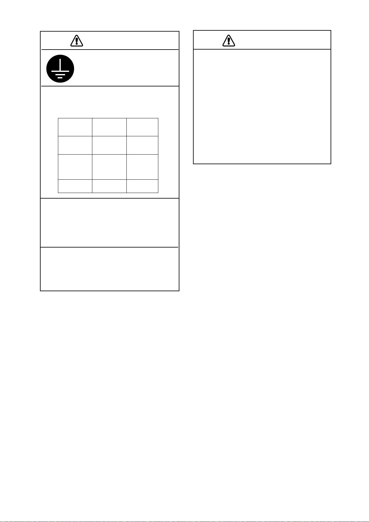
CAUTION
CAUTION
Ground the equipment to
prevent mutual interference.
Observe the following compass safe
distances to prevent interference to a
magnetic compass:
CV-1201
CV-1202
CV-1203
CV-1203M
MU-101C
IF-8000
Standard
compass
0.3 m 0.2 m
0.75 m 0.5 m
0.95 m 0.65 m
Steering
compass
Do not allow warm water or any other
liquid other than seawater or freshwater
to contact the transducer.
The transducer cable must he handled
carefully, following the guidelines
below.
• Keep fuels and oils away from the
cable.
• Locate the cable where it will not be
damaged.
• The cable sheath is made of chloro phrene or polychloride vinyl, which
are easily by damaged plastic solvents
such as toulene. Locate the cable
well away from plastic solvents.
Damage to the transducer may result.
Do not install the transducer where
noise or air bubbles is present.
Performance will be affected.
ii
Page 5
SYSTEM CONFIGURATION
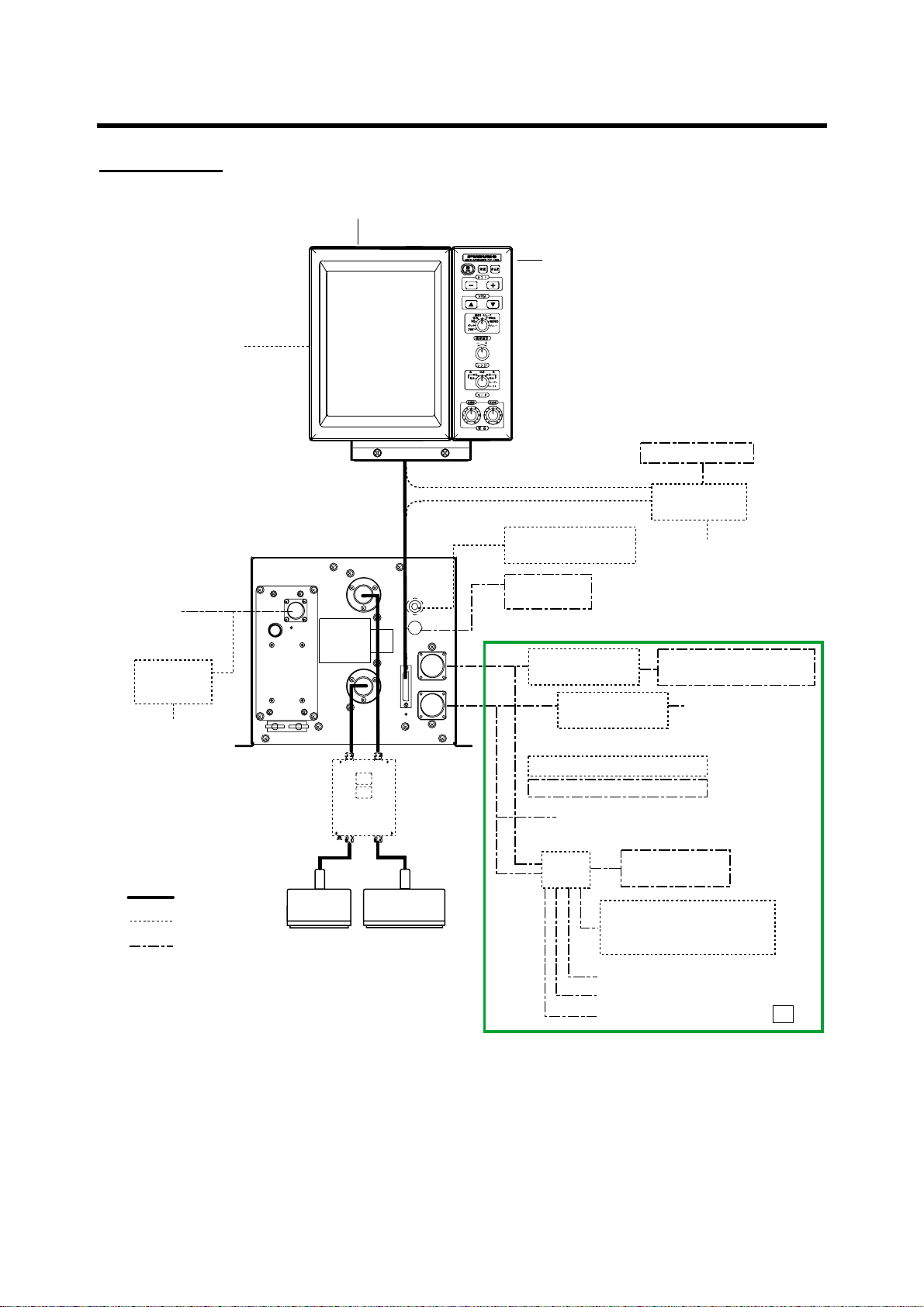
Standard type
MONITOR UNIT MU-101C
CONTROL UNIT
CV-1201: Portrait type
CV-1202: Landscape type
Navigator *4
Ship's Mains
12-24 VDC
Rectifier
RU-1746B-2
100/110/115/200/
220/230 V AC
1φ, 50/60 Hz
NMEA 0183
PROCESSOR UNIT
CV-1203 (FCV-1200L)
CV-1203M (FCV-1200LM)
Booster Box
BT-5
: Standard
: Option
: Local Supply
Low
Frequency
Transducer*1
HI
LO
High
Frequency
Transducer*1
Water Temp. Sensor
(T-02MSB, etc.)
Net Sonde
FNZ-18
E/S Interface
VI-1100A
E/S Interface
VI-1100A
OR
Transceiver Unit ETR-5D/10D
T elesounder TS-7000/8000 *3
Same as above
OR
Switch Box
EX-7
Picture Recorder
E/S Interface VI-1100A
Transmitter Unit ETR-5D/10D
External Monitor
Interface Unit
IF-8000
Navigator *4
Sonar, Net Recorder,
Telesounder TS-50/80 *3
Same as above
MT-12
OR
*1: FCV-1200L only
*2: EXIF Assy. required for FCV-1200L.
*3: For sister ship one unit only
Sister ship: EXIF Assy. required for FCV-1200L
Master ship: FCV-1200LM or FCV-1200L equipped with EXIF Assy.
*4: Navigator may be connected to interface unit or monitor unit.
iii
Same as above
Same as above
Same as above
*2
Page 6
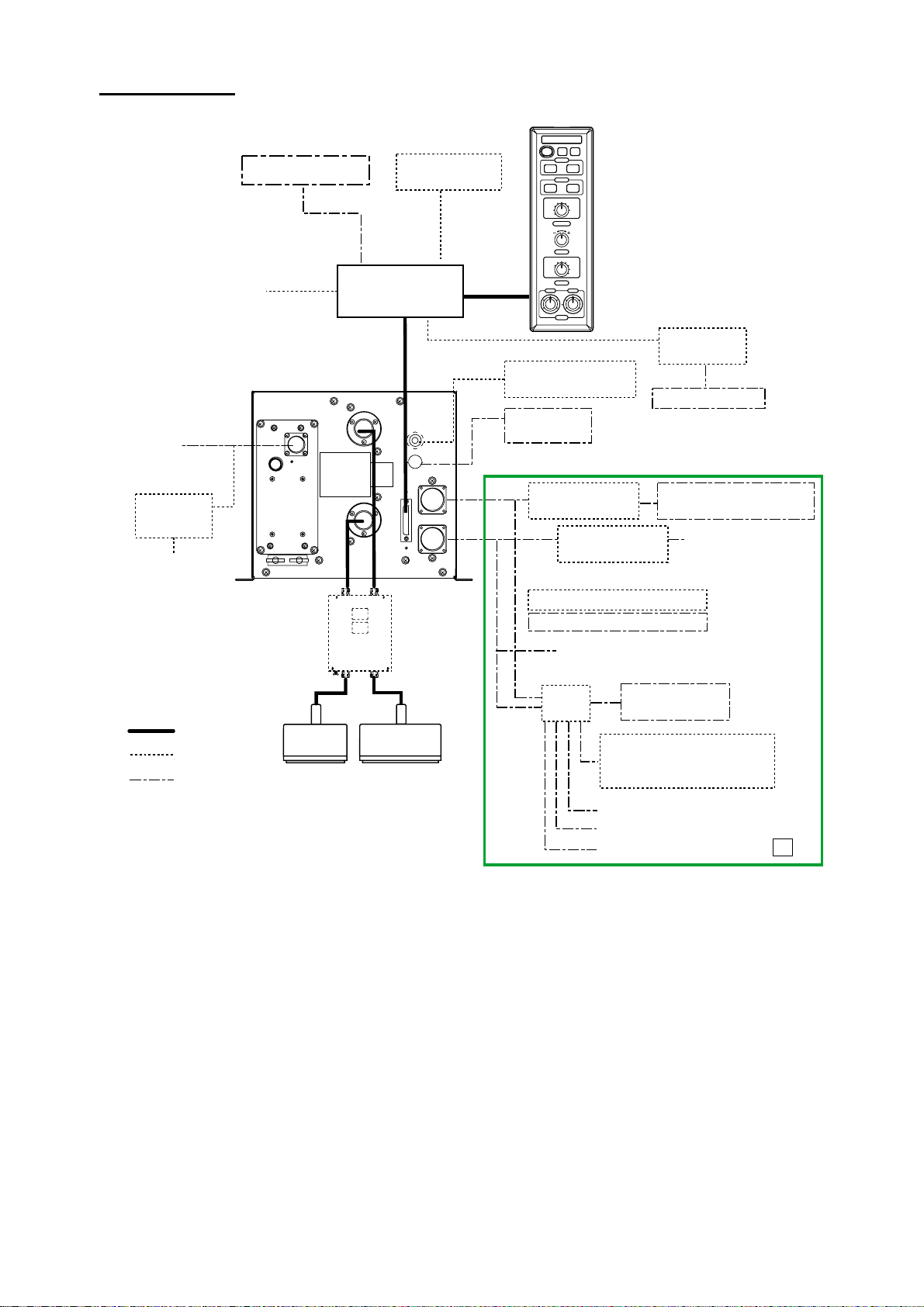
Blackbox type
Ship's Mains
12-24 VDC
Rectifier
RU-1746B-2
100/110/115/200/
220/230 V AC
1φ, 50/60 Hzz
External Monitor
Navigator
PROCESSOR UNIT
CV-1203 (FCV-1200L)
CV-1203M (FCV-1200LM)
: Standard
: Option
: Local Supply
NMEA 0183
Booster Box
BT-5
Low
Frequency
Transducer*1
MONITOR UNIT
MU-101C
Interface Unit
IF-8000
HI
LO
High
Frequency
Transducer*1
CONTROL UNIT
*4
Water Temp. Sensor
(T-02MSB, etc.)
Net Sonde
FNZ-18
E/S Interface
VI-1100A
OR
Transceiver Unit ETR-5D/10D
T elesounder TS-7000/8000 *3
OR
Switch Box
EX-7
CV-1201: Portrait type
CV-1202: Landscape type
E/S Interface
VI-1100A
Same as above
Picture Recorder
E/S Interface VI-1100A
Transmitter Unit ETR-5D/10D
Interface Unit
IF-8000
External Monitor
Sonar, Net Recorder,
Telesounder TS-50/80 *3
Same as above
MT-12
OR
*1: FCV-1200L only
*2: EXIF Assy. required for FCV-1200L.
*3: For sister ship one unit only
Sister ship: EXIF Assy. required for FCV-1200L
Master ship: FCV-1200LM or FCV-1200L equipped with EXIF Assy.
*4: When connecting optional monitor unit, connect it to control unit.
iv
Same as above
Same as above
Same as above
*2
Page 7
EQUIPMENT LISTS
Standard supply
Name Type Code No. Qty Remarks
CV-1201/MU-101C
Monitor Unit
Processor Unit
Spare Parts SP02-04200 000-012-451 1 set SP02-04001 (Processor Unit)
Accessories
Installation
Materials
Transducer
CV-1202/MU-101C
CV-1203
CV-1203M
FP02-05100 000-012-474
FP02-05110 000-012-475
CP02-06540
(FCV-1200L,
unibody)
CP02-06560
(FCV-1200LM,
unibody)
CP02-06500
(FCV-1200L,
unibody)
CP02-06510
(FCV-1200LM,
unibody)
CP02-06550
(FCV-1200L,
unibody)
CP02-06570
(FCV-1200LM,
unibody)
Transducer available in 1, 2 and 3 kW models. See page ix - xx for details. No selection
also available.
000-012-464
000-012-466
000-012-453
000-012-454
000-012-465
000-012-467
−
−
−
−
1 set
1 set
Portrait type
1
Landscape type
For FCV-1200L
1
For FCV-1200LM
For landscape-type monitor unit,
FP02-05101 (Hanger),
FP06-01102 (Hood)
For portrait-type monitor unit,
FP02-05101 (Hanger), FP02-05022
(Hood)
06S4078 *1.5* m
MJ-A10SPF0002-0015 (0.15 m)
CP02-06501
06S4078 *1.5* m
MJ-A10SPF0002-0015 (0.15 m)
CP03-06511
06S4078 *5* m
MJ-A10SPF0002-0015 (0.15 m)
CP02-06501
06S4078 *5* m
MJ-A10SPF0002-0015 (0.15 m)
CP02-06511
06S4078 *10* m
MJ-A10SPF0002-0015 (0.15 m)
CP02-06501
06S4078 *10* m
MJ-A10SPF0002-0015 (0.15 m)
CP02-06511
Select one, with
SP06-01101 (for
dislay unit)
v
Page 8

Blackbox type
Name Type Code No. Qty Remarks
CV-1201-E-15
−
1.5 m cable,
portrait type
CV-1201-E-50
Control Unit
CV-1202-E-15
CV-1202-E-50
CV-1203
Processor Unit
CV-1203M
−
1
−
−
−
1
−
Spare Parts SP02-04210 000-012-452 1 set
Interface Unit
IF-8000
−
1
FP06-01120 006-556-260 1 set Landscape-type
Accessories
FP02-05111 001-413-710 1 Flush mount type
06-021-2121 100-320-101 1
Installation
Materials
Transducer
CP02-06520
(FCV-1200L)
CP02-06530
(FCV-1200LM)
CP02-06680
(FCV-1200L)
CP02-06690
(FCV-1200LM)
CP02-06610 000-012-480 1.5m cable
CP02-06620 000-012-481
Transducer available in 1, 2 and 3 kW models. See page ix - xx for details. No selection
also available.
000-012-455
000-012-456
1 set
000-012-468
000-012-469
1 set
5 m cable,
portrait type
1.5 m cable,
Select
one
landscape type
5 m cable,
landscape type
No transducer
With transducer
SP02-04001 (Processor Unit)
SP06-01111 (Interface Unit)
Hard cover
For Control Unit
06S4078 *5* m
CP02-06501
06S4078 *5* m
CP02-06511
06S4078 *10* m
CP02-06501
06S4078 *10* m
CP02-06511
5m cable
Optional equipment
Name Type Code No. Qty Remarks
Monitor Unit MU-101C-H
Monitor Unit MU-101C-V
Echosounder
VI-1100A
Interface
Switch Box EX-7
(Continued on next page.)
−
−
−
−
vi
1 set Landscape type, with spare parts
and accessories
1 set Portrait type, with spare parts and
accessories
Page 9

Optional equipment (con’t)
Rectifier RU-1746B-2
Cable
Transceiver
Unit
Water
Temperature
Sensor
Connector
EXIF Board
Assy.
Interface Unit IF-8000
Unibody
monitor unit
flush mount kit
Separate
monitor unit
flush mount kit
Control unit
flush mount kit
Separate
installation kit
Cable Assy. 80-0654 001-413-880 1 For program ver.up
Booster Box BT-5
MJ-A6SPF0012-050 000-134-424 1 6 pin-6 pin, 5 m, for navigator
MJ-A6SPF0012-100 000-133-817 1 6 pin-6 pin, 10 m, for navigator
MJ-A6SPF0011-050 000-132-244 1 6 pin-4 pin, 5 m, for navigator
MJ-A6SPF0011-100 000-132-336 1 6 pin-4 pin, 10 m, for navigator
MJ-A10SPF0002-0015 000-142-879 1 10 pin-10 pin, 0.15 m, for control unit
MJ-A10SPF0002-050 000-131-411 1 10 pin-10 pin, 5 m, for control unit
06S4078*1.5 m* 000-142-901 1 For monitor unit
06S4078*5 m* 000-142-902 1 For monitor unit
06S4078*10 m* 000-142-900 1 For monitor unit
NCS255AD-254P-L500 000-142-518 1 For unibody dual-frequency
ETR-5D
ETR-10D
T-02MSB 000-040-040 1 Thru-hull mount
T-02MTB 000-040-026 1 Transom mount
T-03MSB 000-040-027 1 Thru-hull mount
SRCN6A25-24P 000-508-676 1 For EXIF Board Assy.
FM14-8P 000-511-408 1 For FNZ-18
NCS-254-P 000-506-505 1 For connection of transducer
OP02-81 000-012-463 1 set For FCV-1200L
OP06-16 006-556-300 1 set For monitor unit and control unit
OP06-17 006-556-310 1 set For monitor unit
OP06-18 006-556-320 1 set For control unit, Blackbox type
OP02-83-1.5 001-413-600 1 set 1.5 m cable
OP02-83-5 001-413-610 1 set 5 m cable
OP06-15-1.5 006-559-140 1 set 1.5 m cable
OP06-15-5 006-559-150 1 set 5 m cable
CV-1201-E
CV-1202-E
−
−
−
−
−
−
−
transducer
1 set
1 set
1 set
1 Portrait type Control Unit
1 Landscape type
1
Unibody flush
mount
Unibody
tabletop
vii
Page 10

Available transducers
1 kW transducer
ycneuqerF
)zHk(
54/51
05/51
86/51
88/51
002/51
lluH
lairetaM
leetS
PRF
leetS
PRF
leetS
PRF
leetS
PRF
leetS
PRF
leetS
PRF
leetS
PRF
recudsnarT
S4-F51
H3-F54
S4-F51
B6/6-B05
S4-F51
B9-B05
S4-F51
G8-F05
S4-F51
H8-F86
S4-F51
8-B88
S4-F51
S5-B002
lluH-urhT
epiP
knaT
leetS
54/82
PRF
leetS
PRF
leetS
05/82
PRF
leetS
PRF
leetS
86/82
PRF
leetS
88/82
PRF
leetS
002/82
PRF
leetS
88/54
PRF
8-F82
H3-F54
8-F82
B6/6-B05
8-F82
B9-B05
8-F82
G8-F05
8-F82
H8-F86
8-F82
8-B88
8-F82
S5-B002
H3-F54
8-B88
)2(0006-BWT656-T
)2(0006-BWT756-T
viii
Page 11

1 kW transducer (con’t)
ycneuqerF
)zHk(
002/54
88/05
lluH
lairetaM
leetS
PRF
leetS
PRF
leetS
PRF
leetS
PRF
leetS
PRF
leetS
PRF
8-B88
8-B88
8-B88
recudsnarT
H3-F54
S5-B002
B6/6-B05
B9-B05
G8-F05
B6/6-B05
S5-B002
B9-B05
S5-B002
lluH-urhT
epiP
)2(0006-BWT856-T
knaT
leetS
002/05
PRF
leetS
PRF
leetS
PRF
leetS
PRF
leetS
004/05
PRF
leetS
PRF
leetS
002/86
PRF
G8-F05
S5-B002
T1-002/05
TS1-002/05
B6/6-B05
25-B004
B9-B05
25-B004
G8-F05
25-B004
H8-F86
S5-B002
002/88
leetS
PRF
8-B88
S5-B002
ix
Page 12

2 kW transducer
ycneuqerF
)zHk(
54/51
05/51
86/51
88/51
002/51
54/82
05/82
lluH
lairetaM
leetS
PRF
leetS
PRF
leetS
PRF
leetS
PRF)2(0011-BRTF-926-T
leetS
PRF)2(0011-BRTF-236-T
leetS
PRF
leetS
PRF
01-F51
H6-F54
01-F51
21-B05
01-F51
H03-F86
01-F51
01-B88
01-F51
81-F82
H6-F54
81-F82
21-B05
recudsnarT
N8/B8/8-B002
lluH-urhT
epiP
)2(0007-BFT726-T
)2(0007-BFT926-T
)2(0007-BFT236-T
)2(0007-BFT436-T
knaT
leetS
86/82
PRF)2(0011-BRTF-436-T
leetS
88/82
PRF)2(0011-BRTF-636-T
leetS
002/82
PRF)2(0011-BRTF-836-T
leetS
88/54
PRF
002/54
88/05
002/05
leetS
PRF
leetS
PRF)2(0011-BRTF-346-T
leetS
PRF
81-F82
H03-F86
81-F82
01-B88
81-F82
N8/B8/8-B002
H6-F54
01-B88
H6-F54
N8/B8/8-B002
21-B05
01-B88
21-B05
N8/B8/8-B002
)2(0007-BFT636-T
)2(0007-BFT836-T
)2(0007-BFT346-T
)2(0007-BFT546-T
leetS
002/86
PRF)2(0011-BRTF-546-T
002/88
leetS
PRF)2(0011-BRTF-946-T
H03-F86
N8/B8/8-B002
01-B88
N8/B8/8-B002
)2(0007-BFT946-T
x
Page 13

3 kW transducer
ycneuqerF
)zHk(
leetS
54/51
PRF
*: 5 kW transducer.
lluH
lairetaM
recudsnarT
2X01-F51
H21-F54
lluH-urhT
epiP
knaT
05/51
leetS
PRF
leetS
86/51
PRF
leetS
88/51
PRF
leetS
701/51
PRF
leetS
051/51
PRF
leetS
002/51
PRF
leetS
54/82
PRF
leetS
05/82
PRF)2(0011-BRTF-186-T
2X01-F51
H42-F05
2X01-F51
H03-F86
2X01-F51
H*621-F88
2X01-F51
R01-B001
2X01-F51
H21-B051
2X01-F51
H*21-B002
H42-F82
H21-F54
H42-F82
H42-F05
)2(0007-BFT186-T
86/82
leetS
PRF
leetS
88/82
PRF)2(0011-BRTF-286-T
leetS
701/82
PRF
leetS
051/82
PRF)2(0011-BRTF-386-T
leetS
002/82
PRF)2(0011-BRTF-386-T
leetS
88/54
PRF
leetS
701/54
PRF
leetS
051/54
PRF
H42-F82
H03-F86
H42-F82
H*621-F88
H42-F82
R01-B001
H42-F82
H21-B051
H42-F82
H21-B002
H21-F54
H621-F88
H21-F54
R01-B001
H21-F54
H21-B051
)2(0007-BFT286-T
)2(0007-BFT386-T
)2(0007-BFT386-T
xi
Page 14

3 kW transducer (con’t)
ycneuqerF
)zHk(
002/54
lluH
lairetaM
leetS
PRF
*: 5 kW transducer.
recudsnarT
H21-F54
H*21-B002
lluH-urhT
epiP
knaT
88/05
leetS
PRF)2(0011-BRTF-286-T
leetS
701/05
PRF
leetS
051/05
PRF)2(0011-BRTF-386-T
leetS
002/05
PRF)2(0011-BRTF-386-T
leetS
701/86
PRF
leetS
051/86
PRF)2(0011-BRTF-646-T
leetS
002/86
PRF)2(0011-BRTF-646-T
leetS
051/88
PRF
H42-F05
H*621-F88
H42-F05
R01-B001
H42-F05
H21-B051
H42-F05
H*21-B002
H03-F86
R01-B001
H03-F86
H*21-B051
H03-F86
H21-B002
H*621-F88
H21-B051
)2(0007-BFT286-T
)2(0007-BFT386-T
)2(0007-BFT386-T
)2(0007-BFT646-T
)2(0007-BFT646-T
002/88
leetS
PRF)2(0011-BRTF-586-T
leetS
002/701
PRF)2(0011-BRT
H*621-F88
H*21-B002
R01-B001
H*21-B002
)2(0007-BFT586-T
)2(0007-BFT
xii
Page 15

1 kW/2 kW transducer
tuptuO
)W(
k2/k1
ycneuqerF
)zHk(
54/51
05/51
86/51
88/51
002/51
54/82
05/82
lluH
lairetaM
leetS
PRF
leetS
PRF)2(0011-BRTF-626-T
leetS
PRF
leetS
PRF)2(0011-BRTF-826-T
leetS
PRF)2(0011-BRTF-136-T
leetS
PRF
leetS
PRF
S4-F51
H6-F54
S4-F51
21-B05
S4-F51
S4-F51
01-B88
S4-F51
8-F82
H6-F54
8-F82
21-B05
recudsnarT
H03-F86
N8/B8/8-B002
lluh-urhT
epiP
)2(0007-BFT626-T
)2(0006-BWT826-T
)2(0006-BWT136-T
knaT
leetS
86/82
PRF
leetS
88/82
PRF
leetS
002/82
PRF
leetS
88/54
PRF
leetS
002/54
PRF
8-F82
H03-F86
8-F82
01-B88
8-F82
N8/B8/8-B002
H3-F54
01-B88
H3-F54
N8/B8/8-B002
)2(0006-BWT756-T
xiii
Page 16

1 kW/2 kW transducer (con’t)
tuptuO
)W(
k2/k1
ycneuqerF
)zHk(
88/05
002/05
lluH
lairetaM
leetS
PRF
leetS
PRF
leetS
PRF)2(0011-BRTF-636-T
leetS
PRF
leetS
PRF
leetS
PRF)2(0001-BRTF-836-T
01-B88
B9-B05
01-B88
G8-F05
01-B88
9-B05
G8-F05
recudsnarT
B6/6-B05
B6/6-B05
N8/B8/8-B002
N8/B8/8-B002
N8/B8/8-B002
lluh-urhT
epiP
)2(0007-BFT636-T
)2(0006-BWT856-T
)2(0007-BFT836-T
knaT
leetS
002/86
PRF
leetS
002/88
PRF
H8-F86
N8/B8/8-B002
8-B88
N8/B8/8-B002
)2(0006-BWT956-T
xiv
Page 17

1 kW/3 kW transducer
tuptuO
)W(
ycneuqerF
)zHk(
54/51
PRF
*: 5 kW transducer.
lluH
lairetaM
leetS
S4-F51
H21-F54
recudsnarT
lluH-urhT
epiP
knaT
05/51
86/51
88/51
701/51
051/51
002/51
54/82
k3/k1
05/82
86/82
leetS
PRF
leetS
PRF
leetS
PRF
leetS
PRF
leetS
PRF)2(0011-BRTF-736-T
leetS
PRF
leetS
PRF
leetS
PRF
leetS
PRF
S4-F51
H42-F05
S4-F51
H03-F86
S4-F51
H*621-F88
S4-F51
R01-B001
S4-F51
H21-B051
S4-F51
H*21-B002
8-F82
H21-F54
8-F82
H42-F05
8-F82
H03-F86
)2(0007-BFT736-T
88/82
leetS
PRF
leetS
701/82
PRF
leetS
051/82
PRF
leetS
002/82
PRF
leetS
88/54
PRF
leetS
701/54
PRF
leetS
051/54
PRF
8-F82
H*621-F88
8-F82
R01-B001
8-F82
H21-B051
8-F82
H*21-B002
H3-F54
H*621-F88
H3-F54
R01-B001
H3-F54
H21-B051
xv
Page 18

1 kW/3 kW transducer (con’t)
tuptuO
)W(
ycneuqerF
)zHk(
002/54
lluH
lairetaM
leetS
PRF
*: 5 kW transducer.
recudsnarT
H3-F54
H*21-B002
lluH-urhT
epiP
knaT
leetS
PRF
88/05
701/05
051/05
k3/k1
leetS
PRF
leetS
PRF
leetS
PRF
leetS
PRF
leetS
PRF
leetS
PRF
leetS
PRF
leetS
PRF
B6/6-B05
H*621-F88
B9-B05
H*621-F88
G8-F05
H*621-F88
B6/6-B05
R01-B001
B9-B05
R01-B001
8-F05
R01-B001
B6/6-B05
H21-B051
B9-B05
H21-B051
G8-F05
H21-B051
leetS
PRF
leetS
002/05
PRF
leetS
PRF
leetS
701/86
PRF
leetS
051/86
PRF
leetS
002/86
PRF
leetS
051/88
PRF
leetS
002/88
PRF
B6/6-B05
H*21-B002
B9-B05
H*21-B002
G8-F05
H*21-B002
H8-F86
R01-B001
H8-F86
H21-B051
H-F86
H*21-B002
8-B88
H21-B051
8-B88
H*21-B002
xvi
Page 19

2 kW/3 kW transducer
tuptuO
)W(
ycneuqerF
)zHk(
54/51
PRF
*: 5 kW transducer.
lluH
lairetaM
leetS
01-F51
H21-F54
recudsnarT
lluH-urhT
epiP
knaT
05/51
86/51
88/51
701/51
051/51
002/51
54/82
k3/k2
05/82
86/82
leetS
PRF
leetS
PRF
leetS
PRF
leetS
PRF
leetS
PRF
leetS
PRF
leetS
PRF
leetS
PRF
leetS
PRF
01-F51
H42-F05
01-F51
H03-F86
01-F51
H*621-F88
01-F51
R01-B001
01-F51
H21-B051
01-F51
H*21-B002
81-F82
H21-F54
81-F82
H42-F05
81-F82
H03-F86
88/82
leetS
PRF
leetS
701/82
PRF)2(0011-BRTF-636-T
leetS
051/82
PRF)2(0011-BRTF-736-T
leetS
002/82
PRF
leetS
88/54
PRF
leetS
701/54
PRF
leetS
051/54
PRF
81-F82
H*621-F88
81-F82
R01-B001
81-F82
H21-B051
81-F82
H*21-B002
H6-F54
H*621-F88
H6-F54
R01-B001
H6-F54
H21-B051
)2(0007-BFT636-T
)2(0007-BFT736-T
xvii
Page 20

2 kW/3 kW transducer (con’t)
tuptuO
)W(
k3/k2
ycneuqerF
)zHk(
002/54
88/05
701/05
051/05
002/05
701/86
051/86
002/86
051/88
002/88
lluH
lairetaM
leetS
PRF
leetS
PRF
leetS
PRF)2(0011-BRTF-346-T
leetS
PRF)2(0011-BRTF-446-T
leetS
PRF
leetS
PRF
leetS
PRF
leetS
PRF
leetS
PRF
leetS
PRF
*: 5 kW transducer.
recudsnarT
H6-F54
H*21-B002
21-B05
H*621-F88
21-B05
R01-B001
21-B05
H21-B051
21-B05
H*21-B002
H03-F86
R01-B001
H03-F86
H21-B051
H03-F86
H*21-B002
01-B88
H21-B051
01-B88
H*21-B002
lluH-urhT
epiP
)2(0007-BFT346-T
)2(0007-BFT446-T
knaT
xviii
Page 21

3 kW/2 kW transducer
tuptuO
)W(
ycneuqerF
)zHk(
54/51
PRF
*: 5 kW transducer.
lluH
lairetaM
leetS
H6-F54
recudsnarT
2X01-F51
lluH-urhT
epiP
knaT
05/51
86/51
88/51
002/51
54/82
05/82
86/82
k2/k3
88/82
leetS
PRF
leetS
PRF
leetS
PRF
leetS
PRF
leetS
PRF
leetS
PRF
leetS
PRF
leetS
PRF
2X01-F51
21-B05
2X01-F51
H03-F86
2X01-F51
01-B88
2X01-F51
N8/B8/8-B002
H42-F82
H6-F54
H42-F82
21-B05
H42-F82
H03-F86
H42-F82
01-B88
002/82
leetS
PRF
leetS
88/54
PRF
leetS
002/54
PRF
leetS
88/05
PRF
leetS
002/05
PRF
leetS
002/86
PRF)2(0011-BRTF-746-T
leetS
002/88
PRF
leetS
002/001
PRF)2(0011-BRTF-946-T
H42-F82
N8/B8/8-B002
H21-F54
01-B88
H21-F54
N8/B8/8-B002
H42-F05
01-B88
H42-F05
N8/B8/8-B002
H03-F86
N8/B8/8-B002
H*621-F88
N8-B002
R01-B001
N8/B8/8-B002
)2(0007-BFT746-T
)2(0007-BFT946-T
xix
Page 22

This page is intentionally left blank.
Page 23
1. MOUNTING
1.1 Monitor Unit, Control Unit
The monitor and control units can be installed as one unit (unibody) or two separate units. The
optional “separate monitor unit installation kit” is necessary when installing them as separate
units. Further, these units can be mounted in a panel (requires optional flush mount kit), together
or separately. See the outline drawings at the back of this manual for details.
Mounting considerations
•
Locate the units out of direct sunlight.
•
The operator should face the bow while viewing the display screen.
•
Select a location where the display screen can be easily observed while operating the control
unit.
•
Leave sufficient space around the units for maintenance and servicing. Recommended
maintenance space appears in the outline drawing at the back of this manual.
Mounting procedure
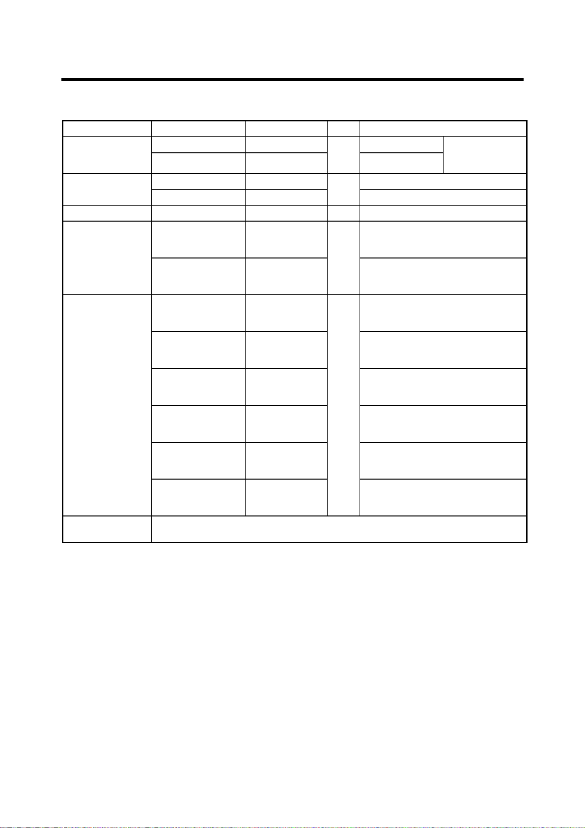
Desktop mounting
1. Fasten the mounting base to the mounting location with four tapping screws.
FRONT
Figure 1-1 Mounting base
1-1
Page 24
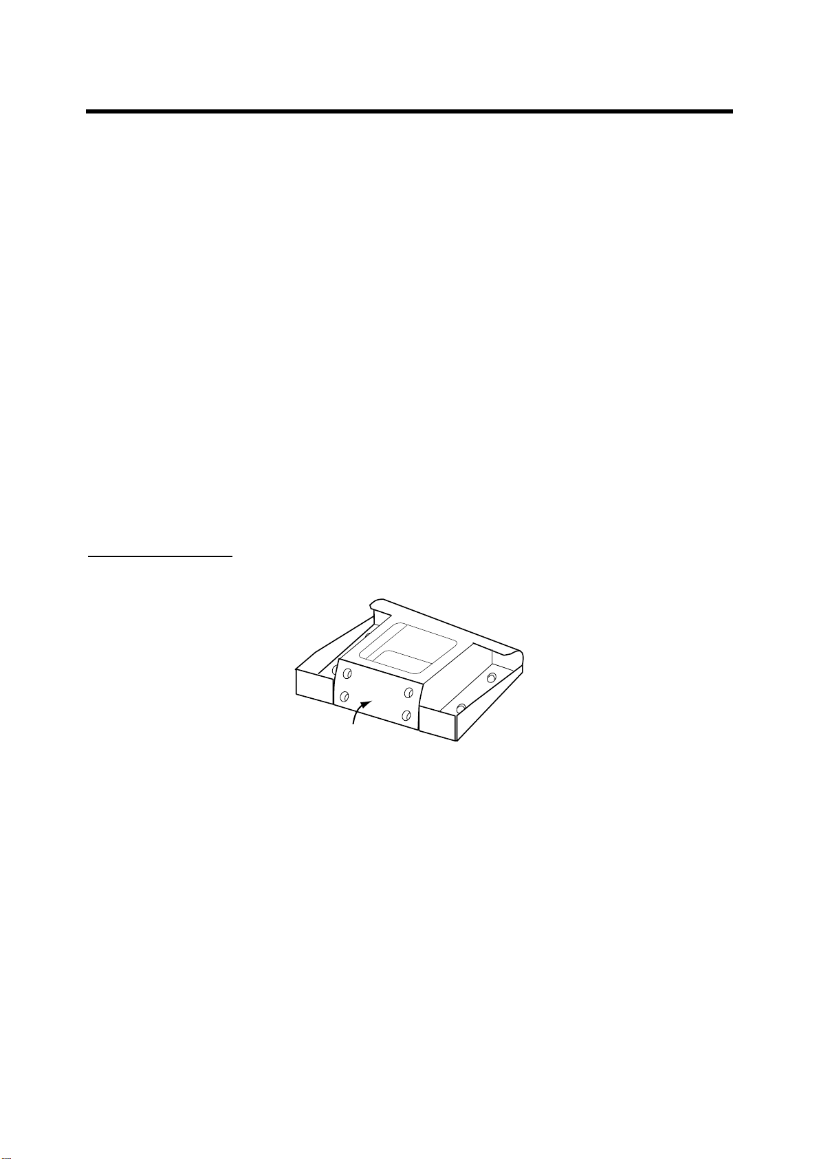
For portrait-type unibody monitor unit
a) Pass the signal cable (connects between interface unit and display unit) through the slot in
the hanger and then connect the cable to the display unit.
HANGER
Signal Cable
Slot
Figure 1-2 Hanger
b) Fasten the hanger at the rear of the display unit with four binding screws (M4X10).
Hanger (rear view)
1
1
3
2
3
2
4
4
Figure 1-3 Hanger, rear view
For landscape-type unibody monitor unit
a) Attach the hanger at the rear of the display unit with four binding screws (M4X10).
Hanger (rear view)
1
2
1
3
3
2
4
1-2
4
Figure 1-4 Hanger, rear view
Page 25
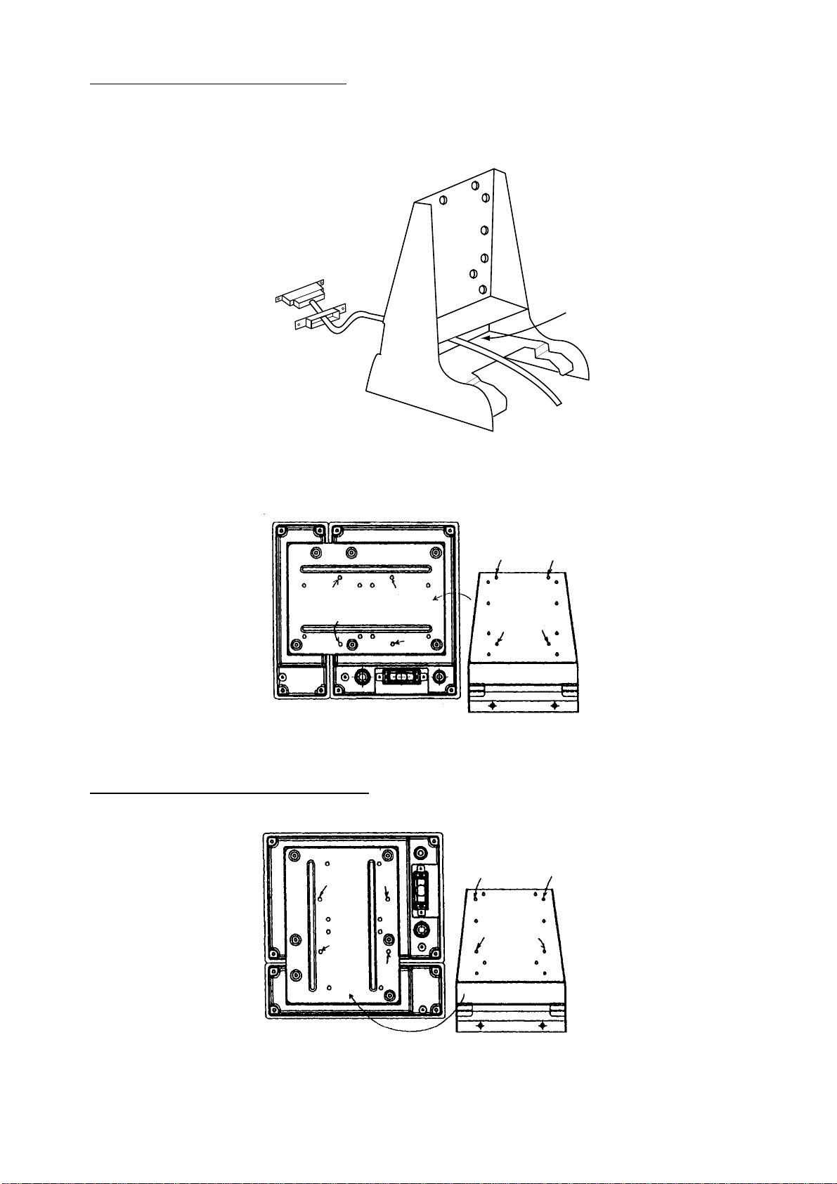
Display unit for separate type, blackbox type (vertical-type control unit)
1. Dismount the coupling place from the rear of the display unit to separate display unit from
control unit.
2. Pass the signal cable (connects between interface unit and display unit) through the slot in
the hanger and then connect the cable to the display unit.
HANGER
Signal Cable
Slot
Figure 1-5 Monitor unit, rear view
3. Attach the hanger at the rear of the display unit with four binding screws (M4X10).
Hanger (rear view)
2
1
4
3
2
1
4
3
Figure 1-6 Hanger, rear view
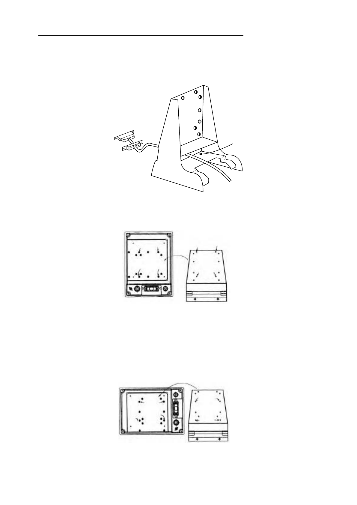
Display unit for separate type, blackbox type (horizontal-type control unit)
1. Dismount the coupling place from the rear of the display unit to separate display unit from
control unit.
2. Attach the hanger at the rear of the display unit with four binding screws (M4X10).
Hanger (rear view)
1
1
2
3
4
3
Figure 1-7 Hanger, rear view
2
4
1-3
Page 26
Hanger (rear view)
1
1
2
3
4
2
4
3
Figure 1-7 Hanger, rear view
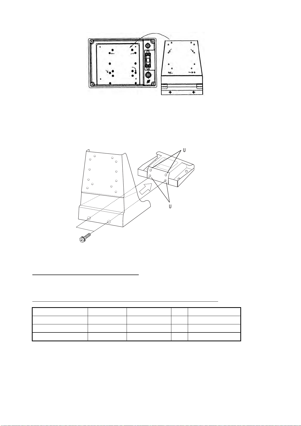
3. Coat threads of upset screws (M6X16, 2 pcs.) used to fasten hanger to mounting base.
4. Fasten the hanger (or display unit) to the mounting base with two upset screws. (Use the
upper holes to tilt the display unit 20°; lower holes to tilt it 9°.)
se these holes to
tilt monitor unit 20˚.
MOUNTING
BASE
se these holes to
tilt monitor unit 9˚.
HANGER
Upset Screw
Figure 1-8 Fastening hanger to mounting base
Unibody monitor unit flush mount kit
Refer to the outline drawing at the back of this manual.
Unib ody monitor un it flush moun t kit: Type OP06-16, Code no. 006-556-300
Name Type Code No. Qty Remarks
Mounting Fixture 06-021-1311 100-279-610 1
Self-tapping Screw 5×20 000-162-609-10 6
Hex-head Screw M4×12 000-162-939- 10 4
1. Make cutout in mounting location referring to page D-2A/D-2B.
2. Using four hex-head screws, fasten control and monitor units together with the mounting
fixture.
1-4
Page 27
Hex-head screws
Mounting fixture
location changes
with monitor
orientation.
Mounting fixture
Figure 1-9 How to flush mount unibody type monitor unit
3. Fasten the monitor unit to the mounting location with six self-tapping screws.
Separate monitor unit flush mount kit
Separate monitor unit flush mount kit: Type OP06-17, Code no. 006-556-310
Name Type Code No. Qty Remarks
Mounting Fixture 06-021-1321 100-279-622 1
Self-tapping Screw 5×20 000-162-609-10 4
Hex-head Screw M4×12 000-162-939- 10 4
1. Make cutout in mounting location referring to page D-8A/D-8B.
2. Fasten mounting fixture to monitor unit four hex-head screws.
Hex-head screws
Mounting fixture location
changes with monitor unit
orientation.
Mounting fixture
Figure 1-10 How to flush mount the control unit
3. Fasten monitor unit with mounting fixture to mounting location with four self-tapping screws.
1-5
Page 28
Separate control unit flush mount kit
Control unit flush mount kit OP06-18 (Code no. 006-556-320)
Separate installation kit OP02-83-1.5 (Code no. 001-413-600)
Separate installation kit OP02-83-5 (Code no. 001-413-610)
Name Type Code No. Qty Remarks
Mounting Fixture 06-021-2101 100-279-731 1
Self-tapping Screw 5×20 000-162-609-10 4
Hex-head Screw M4×12 000-162-939-10 2
Cable Assy.
1. Make cutout in mounting location referring to page D-5A/D-5B.
2. Faste n mounting fixtur e to c o ntr ol unit with two hex- hea d screws.
MJ-A10SPF002-015 000-142-878 1.5 m
MJ-A10SPF002-050 000-131-411 1 5 m
Hex-head screws
OP02-83 only
Mounting fixture location
changes with unit orientation.
Mounting fixture
Figure 1-11 How to flush mount separate type control unit
3. Fasten the control unit to the mounting location with four self-tapping screws.
Separate installation kit
The optional “separate installation kit” or “control unit flush mount kit” is required to install the
monitor and control units separate from one another. Below are the contents of the separate
installation kit. Installation procedure is the same as for the control unit for the blackbox type.
(See next page.) For control unit flush mount kit refer to above section.
Separate installation kit OP06-15-1.5 (with 1.5 m cable, code no. 006-559-140)
Separate installation kit OP06-15-5 (with 5 m cable, code no. 006-559-150)
Name Type Code Qty Remarks
Cable
Control Unit Brack et 06-021-2112 100-281- 880 1
Control Unit Mounting Base 06-021-2111 100-279-740 1
Self-tapping Scr ew 5×20
Hex-head Screw M4×12
Cosmetic Plug DP-687 000-808-417 2
MJ-A10SPF0002-015 000-142-878 1.5 m
MJ-A10SPF0002-050 000-131-411
000-162-608-10
000-162-939-10
1
5 m
2
4
1-6
Page 29
Blackbox type
Supply monitor and interconnection cable (D-sub connector, three rows of 15 pins, max. length
15 m) locally. The monitor connects to the interface unit, and should satisfy the specifications
shown below.
• VGA type
• Analog RGB , 0.7 Vp p, po s iti v e polarity
• TLL level H, V, negative polarity
Control unit for blackbox type
The control uni t com es in two types: portrait and lan dsc a pe . T h e la nds c a pe- type control uni t ca n
be installed on a desktop or flush mounted in a panel. For desktop, the control unit should be
fastened to the control unit mounting base (supplied with accessories). The portrait-type control
unit is designed for flush mounting. For flush mount, the control unit should be fastened to the
mounting fixture (supplied with accessories).
For mounting dimensions see the outline drawing at the back of this manual.
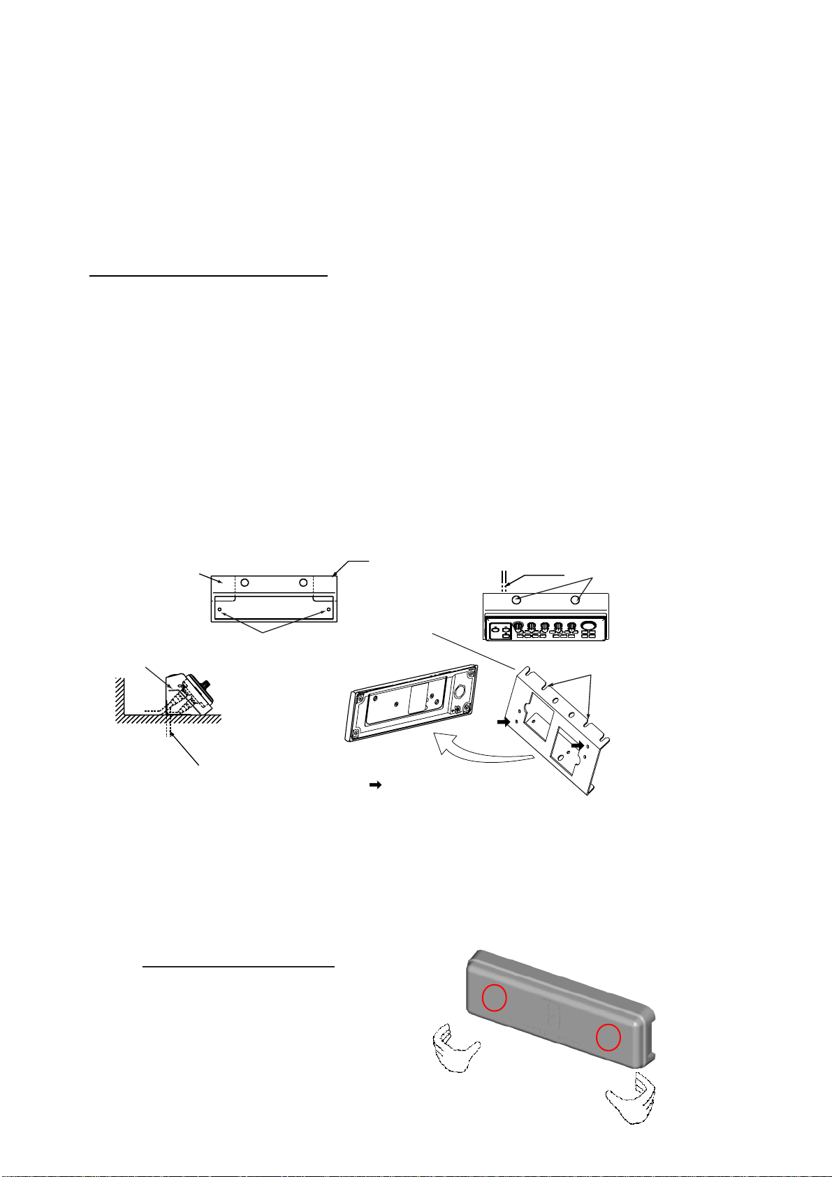
1. Fasten the control unit mounting base to the mounting location with two 5×20 self-tapping
screws.
2. Fasten the control unit to the control unit bracket with two M4×12 hex-head screws.
3. Inserting screwdriver through holes at the top of the control unit mounting base, loosely
screw in two M4×12 hex-head screws.
Cable
entrance
Control unit
bracket
Self-tapping screw
x
20)
(M5
Control unit
(rear)
Cable can be led in
through here.
Control unit
mounting base
Control unit
bracket
: Fix with hex-head screws.
Cable
Fasten control unit
bracket from here.
Set to screws loosely
fastened at step 3.
Figure 1-12 How to mount the control unit for blackbox type
4. Set the control unit to the control unit mounting base and fasten hex-head screws inserted
at step 3.
5. Set cosmetic plugs (2 pcs.) to the holes at the top of the control unit mounting base.
6. Attach hard cover to protect the control unit.
How to remove the hard cover
Place your thumbs at the locations shown with
circles in the illustration at right, and then lift the
cover while pressing it with your thumbs.
1-7
Page 30

1.2 Processor Unit
There are two types of Processor Units: CV-1203 (FCV-1200L) and CV-1203M (FCV-1203LM).
With the EXIF Board Assy. (standard on FCV-1200LM, optional on FCV-1200L) external
equipment such as an echosounder interface, switch box, etc. can be connected.
The unit can be mounted on the deck, a desktop or on a bulkhead. Select a mounting location
considering the points below.
• Locate the uni t out o f direc t su nl i gh t.
• Select a location where temperature and humidity are moderate and stable.
• Consider the length of the cable connected between the processor unit and monitor and/or
interface unit.
• Locate the unit where its cover can be easily removed and cabling easily accessed.
• For mounting on a bulkhead be sure the mounting location is strong enough to support the
unit under the pitching and rolling normally encountered on the v essel.
• Leave sufficient space around the unit for maintenance and servicing. Recommended
maintenance space appears in the outline drawing at the back of this manual.
Tabletop or deck mounting: Fasten with four self-tapping screws.
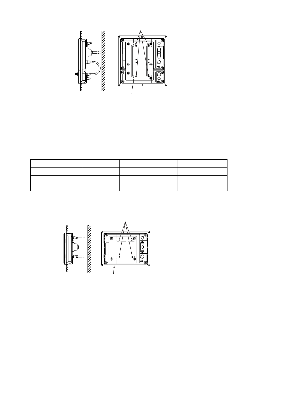
Bulkhead mounting: Screw in four
protrudi n g. Set the pr ocessor unit to t he scr ew s a nd ti gh te n scr ews.
self-tapping screws in mounting location, leaving 5 mm
1-8
Page 31

1.3 Interface Unit
-
The Interface Unit IF-8000 is supplied with the blackbox-type system, and is optional with the
standard type system. It can be mounted on the deck, a desktop or a bulkhead. Select a
mounting location for it considering the following:
• Locate the unit away from areas subject to water splash.
• The length of the cable to processor unit is 10 max.
• Leave sufficient space around the unit for maintenance and servicing. Recommended
maintenance space appears in the outline drawing at the back of this manual.
• For mounting on a bulkhead be sure the mounting location is strong enough to support the
unit under the pitching and rolling normally encountered on the v essel.
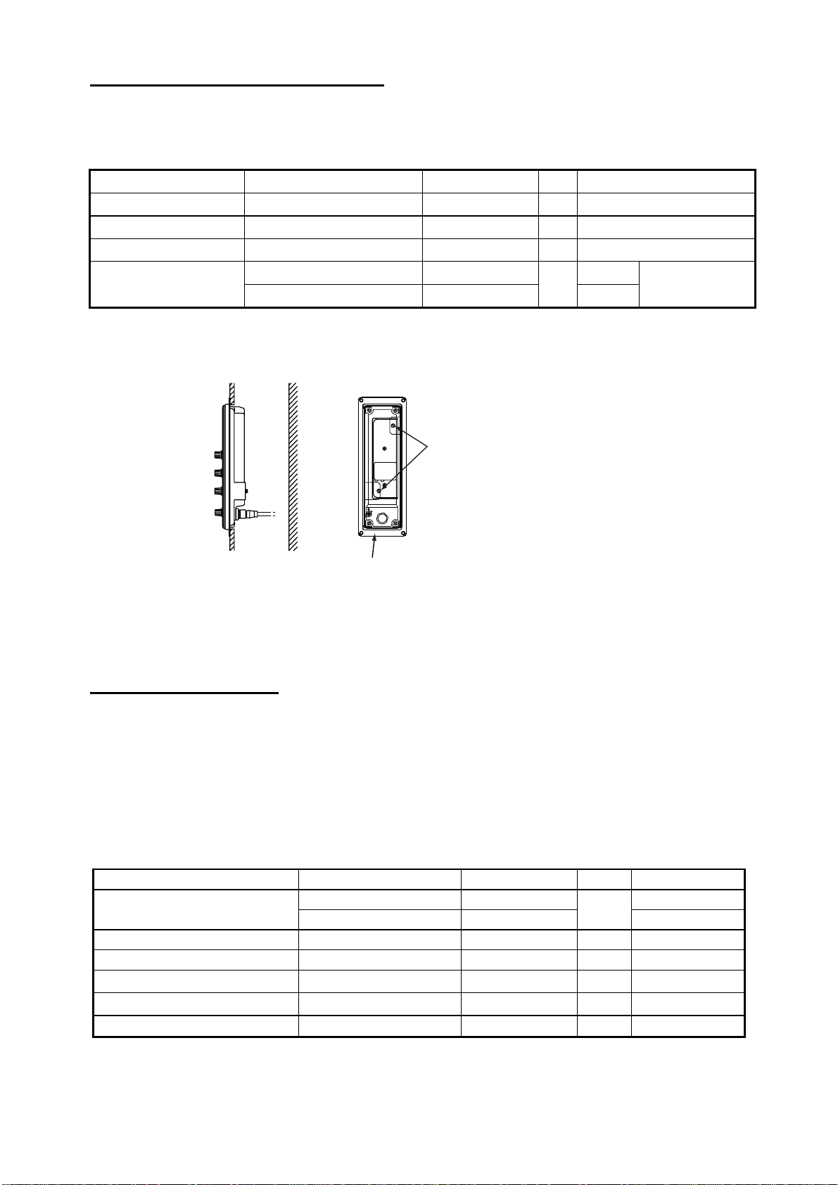
Tabletop or deck mounting: Fasten with four self-tapping screws.
Bulkhead mounting: Screw in self-tapping screws for the upper fixing holes, leaving 5 mm
protruding. Set the interface unit to the screws. Screw in screws for lower fixing holes and
tighten. Finally, tighten screws in upper fi xing holes.
1.4 Transducer
The perfor m an ce o f th e vid eo so un der de pe n ds upo n the tr an s d uc er pos i tion. A place least
affected by air bubbles should be selected since turbulence blocks the sounding path. Further,
select a place least influenced by engine noise. It is known that air bubbles are fewest at the
place where the bow first falls and the next wave rises, at usual cruising speed. In small,
slow-speed boats, the position between 1/3 and 1/2 of the ship’s length from the bow is usually
a good place.
Note: The face of the transducer mu st be facing the sea bottom in normal cruising trim of the
boat.
1.5 Water Temperature Sensor (option)
Transom mount water tem per a t ure sens or T-02 MTB
• Fix the cable at a convenient location
on the transom with the cable clamp.
• When the cable is led through the
transom board, make a hole of
approx. 17 mm in diam eter to pass
the connector. Afte r pass ing the
cable, seal the hole with a sealing
compound.
D>50 cm
D
Figure 1
13 How to m ount transom mount
water temp er ature sensor T-02MTB
5X20
Flush with hull bottom
1-9
Page 32

Thru-hull m ount wa ter t emper at ure se ns or T-02MSB, T-03MSB
Select a suitable mounting location considering the following points:
• Selec t a mid- b oat flat positio n. The sensor do es n ot have to be instal led perfectl y
perpendicular; however, the location should not be such that the transducer may be damaged
when the boat is dry-docked.
• Locate aw ay from equipm en t which gives off heat.
• Locate away from drain pipes.
• Select a location where vibration is minimal.
T-02MSB T-03MSB
Sensor Holder
Sensor
cable
Locknut
Washer
Gasket
φ21 mm
φ25 mm
Locknut
Locknut
Washer
Gasket
Coat with
sealant.
Coat with
sealant.
Mounting procedure
1. Drill a hole of 21 mm in diameter in
the mounting location.
2. Pass the sensor cable through the
hole.
3. Pass gasket, washer and locknut
onto cable in that order.
4. Coat the sensor flange with high
quality sealant and then fasten the
sensor with the locknut.
(Torque: max. 59N·m)
5. Launch the boat to check for water
leakage around the sensor.
Holder Guide
Mounting procedure
1. Drill a hole of 25 mm in diameter in the mounting
location.
2. Coat holder guide with high quality sealant, and
pass gasket, washer and locknut onto holder
guide in that order and then tighten the locknut.
3. Set the sensor holder to the holder guide from
inside the boat and then tighten the locknut.
4. Launch the boat to check for water leakage
around the sensor.
Plate thickness within
25 mm
Figure 1-14 Assembling thru-hull water temperature sensor T-02MSB, T-03MSB
1.6 Booster Box (option)
The Booster Box enables connection of a 5 kW transducer (28F-38M, 50F-38). You can also
connect a 10 kW transducer (28F-72, 50F-70), however the maximum output power will be 5
kW
. For furt her details see i ts operator’s manual.
1-10
Page 33

2. WIRING
Refer to the interconnection diagram at the back of this manual for detailed information.
If the D-sub connector (used with monitor unit, processor unit, interface unit) is too large to pass
through a hole, remove the connector cover. Cover wiring with vinyl tape and pass cable
through hole. This will permit passing of the cable through a hole of 30 mm diameter.
Standard-type FCV-1200L
CONTROL UNIT
CV-1201: Portrait type
CV-1202: Landscape type
PROCESSOR UNIT
CV-1203
Ship's Mains
12-24 VDC
DPYCYS-2.0
Rectifier
RU-1746B-2
100/110/115/200/
220/230 VA C
1φ, 50/60 Hz
: Standard
: Option
: Local Supply
*1: FCV-1200L only
*2: Requires EXIF Assy.
*3: For sister ship one unit only
Sister ship: Requires EXIF Assy.
Master ship: Requires EXIF Assy.
*4: Navigator may be connected to either monitor unit or interface unit.
*5: Cable between monitor unit and control unit
Unibody - MJ-A10SPF0002-0015
Separate - MJ-A10SPF0002-015, MJ-A10SPF0002-050
*6: A + B < 15 m
A + C < 15 m
06S4078 (1.5m/5m/10m)
High
Frequency
Transducer*1
*5
06S4078
*1.5m/5m/10m*
Low
Frequency
Transducer*1
MONITOR UNIT
MU-101C
NMEA 0183
Navigator *4
06S4078 (1.5m/5m/10m)
TEMP
SONDE
HI
LO
Water Temp. Sensor
(T-02MSB, etc.)
Net Sonde
FNZ-18
Transceiver Unit ETR-5D/10D
T elesounder TS-7000/8000 *3
E/S Interface
VI-1100A
E/S Interface
VI-1100A
OR
Same as above
OR
Switch Box
EX-7
Transmitter Unit ETR-5D/10D
Same as above
Same as above
Same as above
External Monitor
B
Interface Unit
IF-8000
A
Navigator *4
External Monitor
Sonar, Net Recorder,
Telesounder TS-50/80 *3
Same as above
Picture Recorder
MT-12
E/S Interface VI-1100A
OR
*2
Figure 2-1 Wiring diagram for standard-type FCV-1200L
2-1
Page 34

Blackbox-type FCV-1200L
CONTROL UNIT
CV-1201: Portrait type
CV-1202: Landscape type
Ship's Mains
12-24 VDC
Rectifier
RU-1746B-2
100/110/115/200/
220/230 VA C
1φ, 50/60 Hz
Navigator
DPYCYS-2.0
External Monitor
NMEA 0183
06S4078 (1.5m/5m/10m)
PROCESSOR UNIT
CV-1203
MONITOR UNIT
MU-101C
06S4078 (1.5m/
5m/10m)
Interface Unit
IF-8000
A
LO
C
*4
06S4078 (1.5m/5m/10m)
HI
MJ-A10SPF0002-015
MJ-A10SPF0002-050
Water Temp. Sensor
(T-02MSB, etc.)
Net Sonde
FNZ-18
E/S Interface
VI-1100A
E/S Interface
VI-1100A
OR
Transceiver Unit ETR-5D/10D
T elesounder TS-7000/8000 *3
B
Interface Unit
IF-8000
External Monitor
Sonar, Net Recorder,
Telesounder TS-50/80 *3
Same as above
High
Frequency
Transducer*1
Low
Frequency
Transducer*1
: Standard
: Option
: Local Supply
*1: FCV-1200L only
*2: Requires EXIF Assy.
*3: For sister ship one unit only
Sister ship: Requires EXIF Assy.
Master ship: Requires EXIF Assy.
*4: When connecting optional monitor unit, connect it to control unit.
*5: A + B < 15 m
A + C < 15 m
Figure 2-2 Wiring diagram for blackbox-type FCV-1200L
Same as above
OR
Switch Box
EX-7
Picture Recorder
MT-12
E/S Interface VI-1100A
OR
Transmitter Unit ETR-5D/10D
Same as above
Same as above
Same as above
*2
2-2
Page 35

Standard-type FCV-1200LM
CONTROL UNIT
CV-1201: Portrait type
CV-1202: Landscape type
PROCESSOR UNIT
CV-1203M
Ship's Mains
DPYCYS-2.0
12-24 VDC
Rectifier
RU-1746B-2
100/115/200/
220/230 V AC
1φ, 50/60 Hz
*4
06S4078
*1.5m/5m/10m*
06S4078(1.5m/5m/10m)
MONITOR UNIT
MU-101C
NMEA 0183
Navigator *2
06S4078 (1.5m/5m/10m)
Water Temp. Sensor
(T-02MSB, etc.)
TEMP
SONDE
HI
LO
Net Sonde
FNZ-18
Transceiver Unit ETR-5D/10D
T elesounder TS-7000/8000 *3
E/S Interface
VI-1100A
E/S Interface
VI-1100A
OR
External Monitor
B
Interface Unit
IF-8000
A
Navigator *2
External Monitor
Sonar, Net Recorder,
Telesounder TS-50/80 *1
Same as above
: Standard
: Option
: Local Supply
*1: Sister ship only
*2: Navigator may be connected to either monitor unit or interface unit.
*3: Cable between monitor unit and control unit
Unibody - MJ-A10SPF0002-0015
Separate - MJ-A10SPF0002-015, MJ-A10SPF0002-050
*4: A + B < 15 m
A + C < 15 m
Figure 2-3 Wiring diagram for standard-type FCV-1200LM
Same as above
OR
Switch Box
EX-7
Picture Recorder
MT-12
E/S Interface VI-1100A
OR
Transmitter Unit ETR-5D/10D
Same as above
Same as above
Same as above
2-3
Page 36

Blackbox-type FCV-1200LM
CONTROL UNIT
CV-1201: Portrait type
CV-1202: Landscape type
PROCESSOR UNIT
CV-1203M
Ship's Mains
12-24 VDC
Rectifier
RU-1746B-2
100/110/115/200/
220/230 V AC
1φ, 50/60 Hz
Navigator
DPYCYS-2.0
External Monitor
NMEA 0183
06S4078(1.5m/5m/10m)
MONITOR UNIT
MU-101C
06S4078(1.5m/
5m/10m)
Interface Unit
IF-8000
*3
TEMP
SONDE
HI
LO
MJ-A10SPF0002-015
MJ-A10SPF0002-050
C
*3
06S4078(1.5m/5m/10m)
Water Temp. Sensor
(T-02MSB, etc.)
Net Sonde
FNZ-18
E/S Interface
OR
Transceiver Unit ETR-5D/10D
T elesounder TS-7000/8000 *1
VI-1100A
E/S Interface
VI-1100A
External Monitor
B
Interface Unit
IF-8000
A
C
Interface Unit
IF-8000
External Monitor
Sonar, Net Recorder,
Telesounder TS-50/80 *1
Same as above
OR
Switch Box
: Standard
: Option
: Local Supply
*1: Sister ship only
*2: When optional monitor unit is connected, connect it to the control unit.
*3: A + B < 15 m
A + C < 15 m
Figure 2-4 Wiring diagram for blackbox-type FCV-1200LM
Same as above
Picture Recorder
EX-7
E/S Interface VI-1100A
Transmitter Unit ETR-5D/10D
Same as above
Same as above
Same as above
MT-12
OR
2-4
Page 37

2.1 Wiring Standard Equipment
Transducer (FCV-1200L only)
Separate the transducer cable well away from power cables to prevent interference. Connect the
cable to the transducer connector at the rear of the processor unit. Fabricate the cable as below.
Shield
Connector
Cable Clamp
Shield Foam 71TS-10-1
Cable
Figure 2-5 Fabrication of transducer cable
Note:
For connection of dual-frequency transducer, use cable assy. NCS255AD-254P-L500
(option).
Echosounder interf ace (FCV-1200LM only)
The Echosounder Interface VI-1100A connects external equipment such as a color video
sounder, Transceiver Unit (ETR-5D/ETR-10D), Switch Box EX-7, etc. Attach connector
SRCN6A25-24P (supplied) to the signal cable assy. supplied with the Transceiver Unit.
Note 1:
equipment. Connector SRCN6A25-24P is optionally available.
For the FCV-1200L, the EXIF board assy. (option) enables connection of external
Note 2:
Telesounder may be connected to EXT-H or EXT-L.
(1) Solder connector terminals.
Sheath
Shield
Solder connector terminals.
(2) Cover shield with shield foam where shield is to be clamped.
Sheath
Shield foam (conductive resin tape)
(3) Tighten clamp.
CABLE
Pass connector case onto cable.
Clamp
Sheath
Shield foam
Unfasten two screws.
Figure 2-6 Fabrication of cable, connector for echosounder interface
2-5
Page 38

Power cable
This video sounder is designed to be powered with 12-24 VDC power. To prevent power loss,
use power cable DPYCYS-2.0 (or equivalent) or equivalent. The armor should lie within the
connector case. Confirm polarity when connecting pins.
Lay armor in cable
#1 pin (+)
#2 pin (-)
#3 pin
Taping
Sheath
Core
S = 3.5 mm
φ = 2.4 mm
2
Vinyl Sheath
Shield
Figure 2-7 Fabrication of power cable
Ground
The processor unit, monitor unit and interface unit should be grounded to prevent mutual
interference. Connect an earth plate or earth wire (interface unit) between unit and ship’s
superstructure to ground.
Armor
CAUTION
Ground the equipment to
prevent electrical shock
and mutual interference.
Interface unit IF-8000
The Interface Unit IF-8000 is supplied standard with the FCV-1200LM and is optionally available
with the FCV-1200L.
DATA/VIDEO IN DATA/VIDEO OUT RGB OUT
Cable (06S4078)
from processor
unit
Cable (06S4078)
from monitor unit
or interface
unit
CONT
VGA
Monitor
Cable (06S4079)
from control
unit
NMEA
Navigator
Earth terminal
(Ground to ship's
superstructure.)
GROUND TO
PREVENT MUTUAL
INTERFERENCE.
2-6
Figure 2-8 Interface unit, rear view
Page 39

Use a monitor cable (max. length 15 m) to connect a commercial monitor. A D-sub 15P
connector with three rows of pins is required for connection at the interface unit. The monitor
must satisfy the following requirements:
VGA type
Analog RGB, 0.7Vpp, positive polarity
TTL level H, V, negative polarity
Note 1:
Note 2:
DATA/VIDEO OUT its connector will touch the connector of DATA/VIDEO IN. To prevent this, cut
and remove the rubber covers and fixing metals from the connectors as below to attach them to
the interface unit.
Two interface units may be connected.
When connecting the Monitor Unit MC-101C or an interface unit to the terminal
Connectors touch here.
Remove
fixing metals.
Cut and
remove
covers.
Figure 2-9 Remover fixing metals and covers from connectors
of DATA/VIDEO IN and DATA/VIDEO OUT
Note 3:
interface units in parallel, cable lengths should be as below. Further, two cables (type 06S4078)
of 10 m in length cannot be used.
When connecting the interface unit to the Monitor Unit MU-101C or connecting two
2-7
Page 40

2.2 Wiring Optional Equipment
Navigator
Use cable type MJ-A6SPF0011/0012 (option) to connect the navigator to the NMEA connector
on the standard LCD monitor unit or Interface Unit in case of blackbox system. For detailed
information see the interconnection diagram at the back of this manual.
Water temperature sensor T-02MSB, T-02MTB, T-03MSB
Connect the water temperature sensor cable to the TEMP connector on the processor unit.
Net Sonde FNZ-18
Use connector type FM14-8P (option) and five-pair cable CO-SPEVV-SB-C 0.2X5P (or
equivalent, local supply) to connect the Net Sonde to the SONDE connector on the processor
unit. Attach the connector to the cable as below.
Analog sonde signal and sonde temperature may also be input. For details see the
interconnection diagram at the back of this manual.
1. Remove sheath by 15 mm.
3.Solder cores to connector
pins; clamp shield.
Figure 2-11 Fabrication of cable for net sonde
2. Fold back shield onto cable;
cut unused cores.
Wrap with vinyl tape.
4. Tape shield with vinyl tape,
leaving no gap between
clamp and tape.
2-8
Page 41

EXIF board assy.
The EXIF board assy. (type OP02-81, code no. 000-012-463), installed inside the processor unit
CV-1203, is necessary when connecting a telesounder (on sister ship and ma ster ship),
transceiver or other video sounder to the FCV-1200L. Below are the contents of the EXIF board
assy. kit. For connection cable use type S-02-6-10 (24P, 10 m, Code No. 002-962-030).
Name Type Code No. Qty Remarks
EXIF Assy. OP02-81 001-413-440 1
Pan Head Screw M4×10 000-163-191-10 3
SRCN Connector S RCN6A 25- 24P 000-160-740- 10 2
1. Remove the cover o f the pr ocessor unit by unfastenin g 13 sc r ews (M4X8).
Unfasten 13 screws to remove cover.
Left, right, top: 6 (2 screws each side)
Heat sink: 7 screws
Unfasten two screws to remove dummy plate.
Dummy plate
Figure 2-12 Processor unit CV-1203, rear view
2. Unfasten two screws to remove the dummy plate. (The screws and plate may be
discarded.)
3. Unfasten screw marked with % in the figure below. (The screw may be discarded.)
4. Fasten the EXIF board assy. to the chassis with three screws (M4×10, supplied).
*Screw
(M4x10)
J7
POWER
SECTION
Screw
x10)
(M4
MAIN
Board
*- Fasten screw here.
J1
EXIF Board
Assy.
Figure 2-13 Processor unit CV-1203, left side view
5. Connect the EXIF Assy. between J1 on the pcb 02P6278 and J7 on the MAIN board. For
log-type video sounder, see page 3-23.
6. Close the cover.
2-9
Page 42

2.3 Input/Output Sentences
Input sentences
Sentence Data Remarks
GGA Time, position
GLC GRI, TD (Loran C)
GLL Latitude and longitude
GTD TD (Loran C)
MTW Water temperature
RMA Latitude and longitude, TD (Loran C), ground speed and course
RMB Recommended minimum navigation information
RMC Latitude and longitude (GPS), ground speed and course
VTG Speed through the ground and course
hve Heaving data (satellite compass) P sentence
att Roll angle, Pitch angle (satellite compass) P sentence
Output sentences
Sentence Data Remarks
DBS Depth below sea surface Ver. 1.5
DBT Depth below transducer Ver. 1.5
DPT Depth below transducer Ver. 2.0
MTW Water temperature Ver. 1.5. Ver. 2.0 with connection of water
temperature sensor
TLL Target position Ver. 2.0
VRM Water depth Ver. 1.5. Ver. 2.0
CIF input signal
Signal Data Remarks
66 Current (tide) speed, current course
D3 Sonde water temperature, depth
2-10
Page 43

3. INITIAL SETTINGS
This section provides the information necessary for initial setup of the equipment. First turn on
the power and set display language. For the FCV-1200L, enter transducer used, by model
number (FURUNO transducer only) or by specifications. For either model, execute other
procedures as applicable.
3.1 Language Setting
1. Turn on the power. The following display appears.
Note:
The picture on your set may be turned 90
section 3.2.
Please set language.
([ / ]: Select, [+]: Enter)
XXXXXXXX
XXXXXXXX
English
XXXXX
Figure 3-1 Initial display screen
2. Press [ ] to select English, and then press the [+] key to set. The following display appears
on the FCV-1200L only.
Carrry out transducer setting.
Press any key to go to Transducer setting menu.
FCV-1200L:
3.
applicable section(s).
FCV-1200LM:
3.4 and follow the appropriate procedure according to equipment connected (transceiver unit,
external video sounder, picture recorder, telesounder). Then, go to other applicable sections.
Change picture orientation (if necessary) and set transducer type. Then, go to
Change picture orientation (if necessary) and turn off the power. Go to section
(For Japanese customers)
(Japanese)
°
. Picture orientation may be corrected at
3-1
Page 44

3.2 Display Type
If your picture is turned 90° do the following:
1. Press any key to show the installation main menu.
XDCR SETTING INSTALLATION DEMO
XDCR SELECT : XDCR TYPE
[HIGH] FREQ : --- kHz
TRANSDUCER : -----
PWR REDUCTION : OFF
OUTPUT POWER : -- kW
SUPPL Y V OLT : -- V
[LOW] FREQ : --- kHz
TRANSDUCER : -----
PWR REDUCTION : OFF
OUTPUT POWER : -- kW
SUPPL Y V OLT : -- V
[-/+]: Change setting, Turn OFF to exit
Figure 3-2 Installation main menu
2. Press [+] to selection INSTALLATION.
XDCR SETTING INSTALLATION DEMO
MONITOR TYPE : LANDSCAPE
SOUND SPEED : 1500.0 m/s (1~2000)
3-2
[-/+]: Change setting, Turn OFF to exit
Figure 3-3 INSTALLATION menu
Page 45

3. Press [ ] to select MONITOR TYPE, and then press [+] to open the dialog box.
PORTRAIT LANDSCAPE
4. Use [+] or [-] to select appropriate monitor type, and then press [+] to close the dialog box.
5. Turn off the power to change picture orientation.
3.3 Transducer Data (FCV-1200L only)
This paragraph provides information necessary for entering transducer data. You enter
transducer data by either transducer model number (for FURUNO transducer, page 3-4) or
specification (page 3-5). The FCV-1200L is programmed for use with the following
non-FURUNO transducers.
Maker Frequency Transducer Type Remarks
Simrad 38kHz 38E-9-18S1(2kW)
Airmar 38kHz 38E-M42(3kW)
Honda
28kHz 28/55/100(3kW)
33kHz 36/65/110(3kW)
36kHz 32/40(3kW)
41kHz 40/75(3kW)
50/200/400(2kW) 50kHz
50/3K/3F(3kW)
55kHz 28/55/100(3kW)
60kHz 36/65/110(3kW)
67kHz 40/75(3kW)
100kHz 28/55/100(3kW)
118kHz 36/65/110(3kW)
200kHz 50/200/400(2kW)
400kHz 50/200/400(2kW)
50kHz TGM50/200 Suzuki
200kHz TGM50/200
Same as FURUNO 50/200-1T(1kW)
CAUTION
Set the transducer model number
properly.
Wrong transducer setting can damage the
transducer and void the warranty.
CAUTION
Do not enter transducer data by specifications if model number of transducer
used is programmed in the equipment.
Wrong transducer setting can damage the
transducer and void the warranty.
3-3
Page 46

Entering transducer data by transducer model number
Note 1: If you are continuing from paragraph 3.1 go to step 2.
Note 2: If you have already entered transducer settings and want to reconfirm them turn on the
power while pressing any key.
1. Turn on the power.
2. Press any key to show the following menu.
XDCR SETTING INSTALLATION DEMO
XDCR SELECT : XDCR TYPE
[HIGH] FREQ : --- kHz
TRANSDUCER : ---- TX POWER : MAX
OUTPUT POWER : -- kW
SUPPL Y V OLT : -- V
[LOW] FREQ : --- kHz
TRANSDUCER : ---- TX POWER : MAX
OUTPUT POWER : -- kW
SUPPL Y V OLT : -- V
[-/+]: Change setting, Turn OFF to exit
Figure 3-4 Ins tallati on m ai n m en u
3. Press [
] to select [HIGH] FREQ or [LOW] FREQ (whichever is installed), and then press
[+] to show the dialog box. (The appearance of the dialog box depends on the type of
monitor unit used.) The scroll bar at the bottom of the dialog box shows cursor position in
relation to the entire menu.
15 kHz 28 kHz 33 kHz 36 kHz 38 kHz 41 kHz 45 kHz 50 kHz
Scroll bar
4. Press [+] or [-] to select transducer frequency, and then press [
] or [ ] to close the dialog
box.
5. Press [
] to select TRANSDUCER, and then press [+] to open the dialog box. The dialog
box below is for the 200 kHz transducer.
200B-5S (1kW) 50/200-1ST (1kW) 50/200-1T (1 kW) 200 -8/8 (2 kW)
6. Press [+] or [-] to select model number, and then press [
] or [ ] to close the dialog box.
7. To operate the transducer in reduced power (for example, when vessel is in dry dock), press
] to select TX POWER, and then press [+] to open the dialog box.
[
3-4
Page 47

MAX 1/2 1/4 1/8 1/16 MIN
8. Press [+] or [-] to select appropriate power, and then press [
] or [ ] to close the dialog box.
Normally set to MAX. MIN means transmission power less than 1W.
9. Follow steps 1-6 to enter model number of other transducer if installed.
Note: For dual-frequency transducer, enter both high and low frequencies and set the same
transducer model number for both high and low frequencies.
10. Confirm settings and turn off the power.
Note: If the system detects frequency mismatch the message “Frequency unmatch error! Press
any key to go to Transducer setting menu.” appears at the next powering of the equipment.
Press any key to go to the transducer setting menu and reenter transducer data.
Entering transducer data by transducer specifications
For new transducer or other make of transducer see FURUNO Information for further
information.
Note 1: If you are continuing from paragraph 3.1 go to step 2.
Note 2: If you have already entered transducer settings and want to reconfirm them turn on the
power while pressing any key.
1. Turn on the power.
2. Press any key.
3. Press [
TYPE MANUAL
] to select XDCR SELECT, and then press [+] to show the dialog box below.
4. Press [+] to select MANUAL, and then press [
should now look something like the one below.
XDCR SETTING INSTALLATION DEMO
XDCR SELECT : MANUAL
[HIGH] FREQ : --- kHz
SUPPL Y V OLT : --- V
TX POWER : MAX
[LOW] FREQ : --- kHz
SUPPL Y V OLT : --- V
TX POWER : MAX
INVERTER FREQ : STD (62/125/188 kHz)
NOTE: Don't select the item which is
within +/- 3kHz of power supply freq.
Select how to set XDCR type.
] or [ ] to close the dialog box. The display
[-/+]: Change setting, Turn OFF to exit
Figure 3-5 Menu for manual entry of transducer specifications
3-5
Page 48

5. Do the following for both the high and low frequency transducers, or whichever transducer
is installed.
a) Press [ ] to select [HIGH] FREQ or [LOW] FREQ, and then press [+] to open the dialog box.
--- kHz
b) Press [+] or [-] to enter transducer frequency, and then press [ ] or [ ] to close the dialog
box.
c) Press [
d) Press [+] or [-] to enter transducer supply voltage, and then press [
] to select SUPPLY VOLT, and then press [+] to open the dialog box.
--- V
] or [ ] to close the
dialog box.
e) To operate the transducer in reduced power (for example, when vessel is in dry dock),
press [
MAX 1/2 1/4 1/8 1/16 MIN
f) Press [-] to select MAX and then press [ ] or [ ] to close the dialog box.
g) If the transducer frequency and power frequency are the same, noise will be present in the
picture. To prevent this, change the inverter (power) frequency. Press [
INVERTER FREQ, and then press [+] to open the dialog box.
6. Press [+] or [-] to select appropriate power frequency, and then press [
] to select TX POWER, and then press [+] to open the dialog box.
] to select
LO(59/118/177kHz) STD(62/125/188kHz) HI(66/132/198kHz)
] or [ ] to close the
dialog box.
7. Confirm settings and turn off the power.
3-6
Page 49

3.4 Adjustment for Transceiver Unit, Video Sounder,
Telesounder, Picture Recorder
This section provides the settings necessary when connecting a Transceiver Unit (ETR-5D,
ETR-10D, etc.), Color Video Sounder, Telesounder (TS-30/507000/8000) or the Picture
Recorder MT-12.
Note 1: For the FCV-1200L, first install the EXIF board assy. See page 2-7.
Note 2: For the FCV-1200LM, only a master ship’s telesounder can be connected. Further, the
Picture Recorder MT-12 can only play back the echosounder signal; it cannot be used for
recording.
Transceiver unit, video sounder
1. Turn on the power.
2. Turn the [FUNCTION] switch to the MENU position.
3. Press [
] and [+] to select SYSTEM at the top of the screen.
DISP ALM TX/RX USER-1/2 SYSTEM
SYSTEM SETTING
ES/DRAFT SETTING
RANGE SETTING
TEMP SETTING
NET SONDE SETTING
USER COLOR SETTING
USER CLUTTER SETTING
NAV DATA SETTING
TARGET ECHO
STABILIZATION
TEST MODE
DEFAULT SETTING
Menu for system setting.
[+]: Go to setting [EXIT (knob)]: Exit
Figure 3-6 SYSTEM menu
3-7
Page 50

4. Press [ ] to select E/S DRAFT SETTING, and then press [+] to open that menu.
DISP ALM TX/RX USER-1/2 SYSTEM
E/S DRAFT SETTING
<High Frequency>
XDCR CONNECT : INTERNAL
TX POWER : MAX
DRAFT : +0.0 ft (-15~+90)
FREQ CHOICE : **kHz
<Low Frequency>
XDCR CONNECT : INTERNAL
TX POWER : MAX
DRAFT : +0.0 ft (-15~+90)
FREQ CHOICE : ***kHz
E/S SIG OUT : OFF
KP SETTING : INTERNAL
Select transducer connected.
[-/+]: Change set, [EXIT (knob)]: Exit
Figure 3-7 E/S DRAFT SETT ING menu
5. Do the following for both the high and low frequencies, or whichever is installed.
a) Select XDCR CONNECT, and then press [+] to open the dialog box.
INTERNAL ETR TS/OTHER
b) Select INTERNAL or ETR referring to the table below, and then press [ ] or [ ] to close the
dialog box.
Equipment connected
Transceiver Unit ETR OFF
External Video Sounder INTERNAL LF, HF, LF/HF
E/S DRAFT SETTING menu item
XDCR CONNECT E/S SIG OUT
c) If the transceiver or external video sounder is to be used when vessel is in dry dock, select
TX POWER and press [+] to open the dialog box.
MAX 1/2 1/4 1/8 1/16 MIN
d) Press [+] to select appropriate power, and then press [ ] or [ ] to close the dialog box.
3-8
Page 51

For transceiver unit
1. Do the following for both high and low frequencies, or whichever is installed.
a) Use [ ] or [ ] to select DRAFT and press [+] to open the dialog box.
+0.0
b) Use [+] or [-] to enter ship’s draft, and then press [
] or [ ] to close the dialog box.
2. Press [ ] to select E/S SIG OUT, and then press [+] to open the dialog box.
OFF LF HF LF/HF
3. Select OFF, and then press [
] or [ ] to close the dialog box.
4. Turn the [FUNCTION] switch to the EXIT position to quit.
For external video sounder
1. Turn the [FUNCTION] switch to the EXIT position.
2. Do the following for both the high and low frequencies, or whichever is installed.
a) Set the [MODE] switch in the LF, HF or DUAL (dual-frequency transducer only) position.
b) Measure how many feet the transmission line is shifted, by using the VRM marker.
c) If the transmission line is shifted go to step 3, and if it has not shifted, go to step 6.
3. Turn the [FUNCTION] switch to the MENU position.
4. Press [
] and [+] to show the SYSTEM menu.
5. Do the following for both the high and low frequencies, or whichever is installed.
a) Use [ ] or [ ] to select DRAFT, and then press [+] to open the dialog box.
+0.0
b) Use [+] or [-] to enter value measure at step 2, and then press [ ] or [ ] to close the dialog
box.
6. Press [ ] to select E/S SIG OUT, and then press [+] to open the dialog box.
OFF LF HF LF/HF
7. Select LF, HF or LF/HF as appropriate, and then press [
8. Press [
INTERNAL EXTERNAL
] to select KP SETTING and [+] to open the dialog box.
] or [ ] to close the dialog box.
3-9
Page 52

9. Press [+] to select EXTERNAL, and then press [ ] or [ ] to close the dialog box.
10. Turn the [FUNCTION] switch to the EXIT position to quit.
Telesounder
The FCV-1200LM can only be connected to a telesounder on board a master ship and the
FCV-1200L to a telesounder on board a master ship or sister ship.
1. Turn on the power.
2. Turn the [FUNCTION] switch to the MENU position.
3. Press [
4. Press [
] and [+] to select SYSTEM at the top of the screen.
] to select E/S DRAFT SETTING, and then press [+] to open that menu.
5. Do the following for both the high and low frequencies, or whichever is installed.
a) Select XDCR CONNECT, and then press [+] to open the dialog box.
INTERNAL ETR TS/OTHER
b) Select TS / OTHER or INTERNAL referring to the table below, and then press [ ] or [ ] to
close the dialog box.
Equipment connected
Telesounder installed on sister ship INTERNAL LF/HF
Telesounder installed on master ship TS / OTHER OFF
E/S DRAFT SETTI NG menu i t em
XDCR CONNECT E/S SIG OUT
6. Press [ ] to select E/S SIG OUT, and then press [+] to open the dialog box.
OFF LF HF LF/HF
7. Select OFF, LF, HF, LF/HF referring to the table above.
8. Press [
] or [ ] to close the dialog box.
9. Follow the procedure below to set up for telesounder installed on a master ship, or turn the
[FUNCTION] switch to the EXIT position to quit.
Do the following for telesounder installed on master ship
1. Turn the [FUNCTION] switch to the EXIT position.
2. Do the following for both the high and low frequencies, or whichever is installed.
a) Set the [MODE] switch in the LF, HF or DUAL (dual-frequency only) position.
b) Measure how many feet the transmission line is shifted, by using the VRM marker.
c) If the transmission line is shifted go to step 3, and if it has not shifted, go to step 6.
3. Turn the [FUNCTION] switch to the MENU position.
4. Press [
3-10
] and [+] to show the SYSTEM menu.
Page 53

5. Do the following for both the high and low frequencies, or whichever is installed.
a) Use [ ] or [ ] to select DRAFT, and then press [+] to open the dialog box.
+0.0
b) Enter value measured at step 2 with [+] or [-], and then press [ ] or [ ] to close the dialog
box.
Final adjustment (master ship and sister ship)
1. Observer the picture from the sister ship and master ship. The dynamic range of the signal
received at the telesounder is about 6 dB less than that of the raw signal, so set the clutter
control on the telesounder between 2 and 3. This should produce the same picture on both
the master and sister ships.
2. Turn the [FUNCTION] switch to the EXIT position to quit.
Picture recorder
The FCV-1200L can only playback the echosounder signal; FCV-1200LM can record and play
back the echosounder signal.
1. Turn on the power and turn the [FUNCTION] switch to the MENU position.
2. Press [
3. Press [
] and [+] to select SYSTEM at the top of the screen.
] to select E/S DRAFT SETTING, and then press [+] to open that menu.
4. Do the following for both the high and low frequencies, or whichever is installed.
a) Select XDCR CONNECT, and then press [+] to open the dialog box.
INTERNAL ETR TS/OTHER
b) Select INTERNAL or TS / OTHER referring to the table below, and then press [ ] or [ ] to
close the dialog box.
Equipment connected
Record INTERNAL LF + HF
Playback TS / OTHER OFF
E/S DRAFT SETTI NG menu i t em
XDCR CONNECT E/S SIG OUT
5. Press [ ] to select E/S SIG OUT, and then press [+] to open the dialog box.
OFF LF HF LF/HF
6. Select appropriate option referring to the table above, and then press [
dialog box.
7. Turn the [FUNCTION] switch to the EXIT position to quit.
] or [ ] to close the
3-1 1
Page 54

3.5 Water Temperature Sensor Setting
If a water temperature sensor is connected set up as follows:
1. Turn on the power and turn the [FUNCTION] switch to the MENU position.
2. Press [
3. Press [
] and [ +] to select SYST EM at the top of the screen.
] to select TEMP SETTING, and then press [+] to open that menu.
DISP ALM TX/RX USER-1/2 SYSTEM
TEMP SETTING
TEMP INPUT : SENSOR
TEMP ADJUST : +0.0˚F (-20~+20)
TEMP READOUT : ON
TEMP GRAPH : OFF
TEMP COLOR : STD
Select temperature sensor.
[-/+]: Change set, [EXIT (knob)]: Exit
Figure 3-8 TEMP SET TIN G menu
4. The cursor is selecting TEMP INPUT; press [+] to open the dialog box.
SONDE SENSOR NMEA CIF
5. Use [+] or [-] to select source of water temperature data, and then press [
] or [ ] to close
the dialog box.
SONDE: FURUNO Net Sonde FNZ-18 inputs water tempe rature data.
SENSOR: Water temperature sensor T-02MSB, T-02MTB or T-03MSB inputs water
temperat ur e data. This is the default s etting.
NMEA: Water temperature data input from navigation equipment.
CIF: Water temperature data input from CIF of Net Sonde.
6. If you chose SONDE or SENSOR at step 5, you may offset water temperature data to
further refine its accuracy. This must be done with the boat in water.
a) Press [ ] to select TEMP ADJUST, and then press [+] to open the dialog box.
+0.0
b) Watch the water temperature readout on the monitor (if it is not displayed set TEMP
READOUT to ON) and compare it with known value.
3-12
Page 55

c) Use [+] or [-] to enter the difference found in b) above. For example, if the indication of the
,
FCV-1200L is +5
d) Press [
] or [ ] to close the dialog box.
°
higher than the actual value
enter –5 (degrees).
7. Press [ ] to select TEMP READOUT, and then press [+] to open the dialog box.
OFF ON
8. Use [-] or [+] to turn the water temperature indication OFF or ON (default setting)
respectively, and then press [
] or [ ] to close the dialog box.
9. Press [
OFF NARROW STD EXPAND
10. Use [+] or [-] to select the temperature scale graduation interval, and then press [
] to select TEMP GRAPH, and then press [+] to open the dialog box.
] or [ ] to
close the dialog box.
OFF: No water temperature graph
NARROW: Graduation every 2
STD: Graduation every 2.5° (default setting)
°
EXPAND: Graduation every 5.0°
11. Press [
STD WHITE RED BLACK YELLOW
] to select TEMP COLOR and [+] to open the dialog box.
12. Use [+] or [-] to select the color of the water temperature graph for STD (blue in default
setting but color depends on color setting), WHITE, RED, BLACK or YELLOW as
appropriate, and then press [
] or [ ] to close the dialog box.
13. Turn the [FUNCTION] switch to EXIT position to quit.
3-13
Page 56

3.6 Net Sonde Setting
Follow the procedure below when a Net Sonde is connected to the video sounder.
1. Turn on the power and turn the [FUNCTION] switch to the MENU position.
2. Press [
3. Press [
] and [+] to select SYSTEM at the top of the screen.
] to select NET SONDE SETTING, and then press [+] to open that menu.
DISP ALM TX/RX USER-1/2 SYSTEM
NET SONDE SETTING
SONDE MARK : OFF
COLOR : 1
SONDE GRAPH : OFF
GRAPH MODE : SURFACE
GRAPH WIDTH : 1/4
GRAPH RESET : NO
Indication of sonde mark.
[-/+]: Change set, [EXIT (knob)]: Exit
Figure 3-9 NET SONDE SETTING menu
4. The cursor is selecting SONDE MARK; press [+] to open the dialog box.
OFF LF HF
5. Use [+] or [-] to select where to display the sonde marker: OFF, no sonde marker displayed;
LF, low frequency picture, HF, high frequency picture.
6. Press [
7. Press [
8. Use [+] or [-] to select echo level to display, and then press [
] or [ ] to close the dialog box.
] to select COLOR, and then press [+] to open the dialog box.
1 2 3
] or [ ] to close the dialog box.
1: Echo of color level 14 (Reddish-brown in standard color arrangement, default setting)
2: Echo of color level 12 (Red in standard color arrangement)
3: Echo of color level 10 (Orange in standard color arrangement)
3-14
Page 57

9. Press [ ] to select SONDE GRAPH, and then press [+] to open the dialog box.
OFF ON
10. Use [-] or [+] to turn the graph display OFF (default setting) or ON as appropriate, and then
press [
] or [ ] to close the dialog box.
11. Press [
SURFACE BOTTOM
] to select GRAPH MODE, and then press [+] to open the dialog box.
12. Use [-] or [+] to select what temperature to use for the graph, and then press the [
close the dialog box.
SURFACE: First-written water temperature (surface condition, default setting)
BOTTOM: Last-written water temperature (net sonde position)
13. Press [
14. Use [+] or [-] to set width of the sonde graph as desired, and then press [
] to select GRAPH WIDTH, and then press [+] to open the dialog box.
1/4 1/2
] or [ ] to close
the dialog box.
1/4: 1/4 of screen width (default setting)
1/2: 1/2 of screen width
15. Turn the [FUNCTION] switch to EXIT position to quit.
] or [ ] to
3-15
Page 58

3.7 Nav Data, Heading Sensor Setting
Select navigator and heading sensor used as below.
1. Turn on the power and turn the [FUNCTION] switch to the MENU position.
2. Press [
3. Press [
] and [+] to select SYSTEM at the top of the screen.
] to select NAV DATA SETTING, and then press [+] to open that menu. (If a heading
sensor is connected but not a navigator, go to step 10.)
DISP ALM TX/RX USER-1/2 SYSTEM
NAV DATA SETTING
SPEED INFO : OFF
NMEA VERSION : Ver 2.0
NAV DATA : AUTO
COURSE : TRUE
TLL OUTPUT : OFF
Indication of speed data.
[-/+]: Change set, [EXIT (knob)]: Exit
Figure 3-10 NAV DATA SETTING menu
4. The cur s or is selecting SPEED INFO; press [+] to open the dialog box.
OFF ON
5. Use [- ] or [+] t o turn the speed indication OFF (default setting) or ON, and then press [ ] or
[
] to close the dialog box.
6. Press [
Ver 1.5 Ver 2.0 SPECIAL
] to select NMEA VERSION, and then press [+] to open the dialog box.
7. Use [+] or [-] to select NMEA version no. (default setting is Ver 2.0) of the navigator, and then
press [
] or [ ] to close the dialog box. If you are unsure of the version no., try both to see
which one successfully receives position data. SPECIAL is for use with a navigator which has
a baud rate of 600 bps.
3-16
Page 59

8. Press [ ] to select NAV DATA, and then press [+] to open the dialog box.
LC LA DECCA GPS DR AUTO
9. Use [-] or [+] to select type of navigator connected, and then press [ ] or [ ] to close the
dialog box. AUTO (default setting) selects a navigator in the order of GPS, Loran C, Loran A,
Decca, DR (Dead Reckoning).
10. Press [
] to select COURSE, and then press [+] to open the dialog box.
TRUE MAG
11. Use [-] or [+] to select TRUE or MAG (magnetic bearing) as appropriate, and then press [ ]
] to close the dialog box. TRUE is the default setting. If no navigator is connected, turn
or [
the [FUNCTION] switch to other position to quit.
12. Press [
] to select TLL (Target Latitude, Longitude) OUTPUT, and then press [+] to open the
dialog box.
OFF ON
13. TLL OUTPUT enables or disables output of position data from the video sounder to external
equipment, at the moment the [MARKER TLL] key is pressed. Use [+] or [-] to select ON or
OFF (default setting) as appropriate, and then press [
] or [ ] to close the dialog box.
14. Turn the [FUNCTION] switch to EXIT position to quit.
3-17
Page 60

3.8 Stabilization (heaving compensation)
The stabilization feature is available with connection of a satellite compass (SC-50/SC-110) to
the NMEA port and functions to compensate for ship's heaving. Set NMEA output from the
satellite compass as below and follow the accompanying procedure to compensate for heaving.
Output format: IEC ED1
Sentence: ATT, HVE, VTG, GLL
Baud rate: 4800 bps
Interval: 200 ms
1. Turn on the power.
2. Set the FUNCTION control to the MENU position.
3. Press the [▲] key to set the cursor on the top line
and then hit the [+] key to select SYSTEM.
4. Press the [▼] key to select STABILIZATION.
5. Press the [+] key to show the STABILIZATION
menu.
6. Press the [▼] key to select STABILIZATION and
press the [+] key.
7. Use [+] or [-] key to choose OFF or ON as
appropriate and press the [▼] key to confirm
setting.
8. Press the [▼] key to choose SENSOR and press
the [+] key.
9. Use the [-] or [+] key to choose satellite compass
model to use and press the [▼] key to confirm
setting.
10. Press the [▼] key to choose ANT-TD LONG. and
press the [+] key.
11. Use the [-] or [+] key to enter the distance from the
antenna of the satellite compass to this transducer in the fore-aft direction. Enter a "plus"
value if the transducer is closer to the bow than the antenna.
12. Press the [▼] key to confirm setting.
13. Press the [▼] key to choose ANT-TD TRNSV. and press the [+] key.
14. Use the [-] or [+] key to enter the distance from the antenna of the satellite compass to the
transducer in the port-starboard direction. Enter a "plus" value if the transducer is closer to
starboard than the antenna.
15. Press the [▼] key to confirm setting.
16. Press the [▼] key to choose ANT-TD HEIGHT and press the [+] key.
17. Use the [-] or [+] key to enter the distance from the antenna of the satellite compass to this
transducer in the vertical direction.
18. Press the [▼] key to confirm setting.
19. Enter data for
20. Enter data for low frequency similarly.
21. Set the FUNCTION switch to the EXIT position.
DISP ALM TX/RX USER-1/2 SYSTEM
STABILIZATION
STABLIZATION : OFF
SENSOR : SC50/110
<High Frequency>
ANT-TD LONG. : 0.0m (-100 - +100)
ANT-TD TRNSV. : 0.0m (-100 - +100)
ANT-TD HEIGHT : 0.0m (0 -100)
<Low Frequency>
ANT-TD LONG. : 0.0m (-100 - +100)
ANT-TD TRNSV. : 0.0m (-100 - +100)
ANT-TD HEIGHT : 0.0m (0 -100)
Turn on/off stabilization mode.
[+]: Go to setting [EXIT (knob)]: Exit
Figure 3-11 STABILIZATION menu
3-18
Page 61

3.9 Propagation Velocity
This section provides the information for adjustment of propagation velocity. Normally, no
adjustment is necessary, however if the depth indication is wrong, lower or raise propagation
velocity as appropriate.
1. Turn on the power while pressing any key to show the installation main menu.
2. Press [+] or [-] to select the INSTALLATION menu.
XDCR SETTING INSTALLATION DEMO
MONITOR TYPE : LANDSCAPE
SOUND SPEED : 1500.0 m/s (1~2000)
[-/+]: Change setting, Turn OFF to exit
Figure 3-12 INSTALLATION menu
3. Press [
1500.0 m/s
4. Use [+] or [-] to enter value, and then press [
setting is 1500.0 (m/s) and the setting range is 1-2000 (m/s).
5. Turn off the power to quit.
] to select SOUND SPEED, and then press [+] to open the dialog box.
] or [ ] to close the dialog box. The default
3-19
Page 62

3.10 Demonstration Mode
The demonstration mode provides a simulated video sounder picture. Connection of the
transducer is not necessary. All controls are operational.
1. Turn on the power while pressing any key to display the installation main menu.
2. Press [+] to select DEMO.
XDCR SETTING INSTALLATION DEMO
DEMO MODE : OFF
[-/+]: Change setting, Turn OFF to exit
Figure 3-13 DEMO menu
3. Press [
OFF ON
4. Use [+] or [-] to select ON or OFF (default setting) as appropriate, and then press [
to close the dialog box.
5. Turn off the power.
6. Turn on the power. “<DEMO>” appears at the bottom of the screen when the demonstration
mode is on.
] to select DEMO MODE, and then press [+] to open the dialog box.
] or [ ]
3-20
Page 63

3.11 Restoring Default Settings
The procedure below restores most default settings. The following settings are not affected:
target setting, language, demo mode, monitor type (portrait, landscape), transducer settings,
user color settings and user clutter settings.
1. Turn on the power and turn the [FUNCTION] switch to the MENU position.
2. Press [
3. Press [
] and [+] to select SYSTEM at the top of the screen.
] to select DEFAULT SETTING, and then press [+] to open that menu.
DISP ALM TX/RX USER-1/2 SYSTEM
DEFAULT SETTING
DEF A ULT SET : NO
[-/+]: Change set, [EXIT (knob)]: Exit
Figure 3-14 DEFAULT SETTING menu
4. Press [+] to open the dialog box.
[-]: NO [+]: YES
5. Press [+] to restore default settings.
6. Three beeps sound and then normal operation is restored.
3-21
Page 64

3.12 DIP Switch Setting
Interface unit IF-8000
Open the cover of the IF-8000. Set DIP Switch S1 according to system configuration, referring
to the illustration below.
THROUGH
BUFFER
J6
S1
OFF
J1
J2
J3
External
Monitor
J7
Processor
Unit
Processor
Unit
Processor
Unit
Interface
Unit
S1:All OFF
External
Monitor
Interface
Unit
S1:All ON
External
Monitor
Interface
Unit
S1:All OFF
Control
Unit
Monitor
Unit
Control
Unit
Control
Unit
External
Monitor
Interface
Unit
S1:All ON
Figure 3-15 Interface unit, cover removed
EXIF board
Set the DIP switches on the EXIF Board 02P6279 (in the processor unit) according to
equipment connected. No change is necessary when connecting a video sounder which uses a
linear amplifier (FCV-271/382/782, etc.). For video sounder with log amplifier (FCV-1500, etc.)
change the DIP switch settings as below. Early model FURUNO video sounders which have a
log amplifier cannot be connected.
3-22
Page 65

Default setting (for linear amp)
S2
1 2 3 4 5 6 7 8
ON
OFF
S3
1 2 3 4 5 6 7 8
ON
OFF
Setting for log amp
DIP SWITCH S1 DIP SWITCH S2 DIP SWITCH S3
1 2 3 4 5 6 7 8
ON
OFF
1: KP OUT L POS (Default: ON)
2: KP OUT L NEG (Default: OFF)
3: KP IN L POS (Default: ON)
4: KP IN L NEG (Default: OFF
5: LINER IN L (Default: ON)
6: LOG IN L (Default: OFF)
7: KP IN L 12V (OFF, Default)
KP IN L 5 V (ON)
8: WL IN L 12V (OFF, Default)
WL IN L 5 V (ON)
S1
1 2 3 4 5 6 7 8
ON
OFF
1: KP OUT H POS (Default: ON)
2: KP OUT H NEG (Default: OFF)
3: KP IN H POS (Default: ON)
4: KP IN H NEG (Default: OFF
5: LINER IN H (Default: ON)
6: LOG IN H (Default: OFF)
7: KP IN H 12V (OFF, Default)
KP IN H 5 V (ON)
8: WL IN H 12V (OFF, Default)
WL IN H 5 V (ON)
1 2 3 4 5 6 7 8
ON
OFF
1 2 3 4 5 6 7 8
ON
OFF
1: GND (Default: OFF)
2: KP OUT L (Default: OFF)
3: RECO H (Default: ON)
4: ETRREC H (Default: OFF)
5: GND (Default: OFF)
6: KP OUT H (Default: OFF)
7: RECO L (ON)
8: ETRREC L (Default: OFF)
LINEAR AMP (Default setting)
Low frequency
S1-5: ON, S1-6: OFF
High frequency
S2-5: ON, S2-6: OFF
LOG AMP
Low frequency
S1-5: OFF, S1-6: ON
High frequency
S2-5: OFF, S2-6: ON
Figure 3-16 DIP switches on the EXIF board
ETR-2D, 3D, 5D/2, 10D/2, EX-7
Low frequency: (CN8-9: GND)
S3-5: ON, S3-6: OFF
High frequency: CN8-9: GND)
S3-1: ON, S3-2: OFF
NOTE: Do not turn S3-1 and S3-2
and S3-5 and S3-6 ON. This will
cause a short circuit.
3-23
Page 66

APPENDIX 1 TRANSDUCER 50BL-12/50BL-24H
When using the transducer 50BL-12/50BL-24H, see this appendix.
Transducer, thru-hull pipe and tank list
Frequency
(kHz)
50/200 50BL-12/200B-8B
28/50 28F-24H/50BL-24H
50/88 50BL-24H/88F-126H
50/200 50BL-24H/200B-12H
Transducer
Material
Steel
FRP
Steel
FRP
Steel
FRP
Steel
FRP
Settings
Hull
Tank
(Code No.)
T-693
(000-015-044)
T-693F
(000-015-241)
T-696
(000-015-048)
T-696F
(000-015-244)
T-697
(000-015-239)
T-697F
(000-015-245)
T-695
(000-015-047)
T-695F
(000-015-243)
Fasten inside
hull (Code No.)
TWB-6000
(000-015-207)
TWB-1100
(000-015-218)
TWB-6000
(000-015-207)
TRB-1100
(000-015-218)
TWB-6000
(000-015-207)
TRB-1100
(000-015-218)
TWB-6000
(000-015-207)
TRB-1100
(000-015-218)
Fasten outside
hull (Code No.)
TFB-7000
(000-015-209)
-
TFB-7000
(000-015-209)
-
TFB-7000
(000-015-209)
-
TFB-7000
(000-015-209)
-
Referring page 3-5, set XDCR SELECT to MANUAL.
Frequency Output (kW) Transducer Supply
voltage (V)
2 50BL-12 60
50
3 50BL-24H 80
AP-1
Page 67

APPENDIX 2
BLT TRANSDUCERS
The BLT transducer (Bolt-clamp Langevin Transducer) has large bandwidth, good sound
efficiency, compact structure and is reinforced for protection against slamming.
Transducer, thru-hull pipe and tank list
Frequency
(kHz)
28/200 28BL-6HR/200B-8B
38/200 38BL-9HR/200B-8B
50/200 50BL-12HR/200B-8B
28/38 28BL-12HR/38BL-15HR
28/50 28BL-12HR/50BL-24HR
Transducer
Hull
Material
Steel
FRP
Steel
FRP
Steel
FRP
Steel
FRP
Steel
Tank
(Code No.)
T-693
(000-015-044)
T-693F
(000-015-241)
T-693
(000-015-044)
T-693F
(000-015-241)
T-693
(000-015-044)
T-693F
(000-015-241)
T-681
(000-015-849)
T-681F
(000-015-850)
T-681
(000-015-849)
Fasten inside
hull (Code No.)
TWB-6000 (2)
(000-015-207)
TRB-1100 (2)
(000-015-219)
TWB-6000 (2)
(000-015-207)
TRB-1100 (2)
(000-015-219)
TWB-6000 (2)
(000-015-207)
TRB-1100 (2)
(000-015-219)
TWB-6000 (2)
(000-015-207)
TRB-1100 (2)
(000-015-219)
TWB-6000 (2)
(000-015-207)
Fasten outside
hull (Code No.)
TFB-7000 (2)
(000-015-209)
-
TFB-7000 (2)
(000-015-209)
-
TFB-7000 (2)
(000-015-209)
-
TFB-7000 (2)
(000-015-209)
-
TFB-7000 (2)
(000-015-209)
FRP
38/50 38BL-15HR/50BL-24HR
28/88 28BL-12HR/88F-126H
38/88 38BL-15HR/88F-126H
AP-2
Steel
FRP
Steel
FRP
Steel
FRP
T-681F
(000-015-850)
T-681
(000-015-849)
T-681F
(000-015-850)
T-682
(000-015-851)
T-682F
(000-015-852)
T-682
(000-015-851)
T-682F
(000-015-852)
TRB-1100 (2)
(000-015-219)
TWB-6000 (2)
(000-015-207)
TRB-1100 (2)
(000-015-219)
TWB-6000 (2)
(000-015-207)
TRB-1100 (2)
(000-015-219)
TWB-6000 (2)
(000-015-207)
TRB-1100 (2)
(000-015-219)
-
TFB-7000 (2)
(000-015-209)
-
TFB-7000 (2)
(000-015-209)
-
TFB-7000 (2)
(000-015-209)
-
Page 68

APPENDIX 2 BLT T RANSDUCERS
A
50/88 50BL-24HR/88-126H
28/200 28BL-12HR/200B-12H
38/200 38BL-15HR/200B-12H
50/200 50BL-24HR/200B-12H
28/150 28BL-12HR/150B-12H
Steel
FRP
Steel
FRP
Steel
FRP
Steel
FRP
Steel
FRP
T-682
(000-015-851)
T-682F
(000-015-852)
T-683
(000-015-853)
T-683F
(000-015-854)
T-683
(000-015-853)
T-683F
(000-015-854)
T-683
(000-015-853)
T-683F
(000-015-854)
T-683
(000-015-853)
T-683F
(000-015-854)
TWB-6000 (2)
(000-015-207)
TRB-1100 (2)
(000-015-219)
TWB-6000 (2)
(000-015-207)
TRB-1100 (2)
(000-015-219)
TWB-6000 (2)
(000-015-207)
TRB-1100 (2)
(000-015-219)
TWB-6000 (2)
(000-015-207)
TRB-1100 (2)
(000-015-219)
TWB-6000 (2)
(000-015-207)
TRB-1100 (2)
(000-015-219)
TFB-7000 (2)
(000-015-209)
-
TFB-7000 (2)
(000-015-209)
-
TFB-7000 (2)
(000-015-209)
-
TFB-7000 (2)
(000-015-209)
-
TFB-7000 (2)
(000-015-209)
-
38/150 38BL-15HR/150B-12H
50/150 50BL-24HR/150B-12H
Steel
FRP
Steel
FRP
T-683
(000-015-853)
T-683F
(000-015-854)
T-683
(000-015-853)
T-683F
(000-015-854)
Settings
• Referring page 3-5, set the menu as bel ow.
XDCR SELECT: MANUAL
FREQ: 28/38/50 kHz
SUPPLY VOLT 70/90 V
Transducer Output Supply voltage (V)
28BL-6HR 70
38BL-9HR 70
50BL-12HR
28BL-12HR 90
2
70
38BL-15HR 90
50BL-24HR
3
90
TWB-6000 (2)
(000-015-207)
TRB-1100 (2)
(000-015-219)
TWB-6000 (2)
(000-015-207)
TRB-1100 (2)
(000-015-219)
TFB-7000 (2)
(000-015-209)
-
TFB-7000 (2)
(000-015-209)
-
P-3
Page 69

APPENDIX 3 TRANSDUCER 82B-35R
The 82B-35R is a transducer with wide bandwidth of 65 kHz-110 kHz. It is constructed to
provide protection against slamming.
Transducer, thru-hull pipe and tank list
Frequency
(kHz)
15/88
28/88 28F-18/82B-35R
50/88
15F-4S/82B-35R
15F-10/82B-35R
50F-8G/82B-35R
50B-12/82B-35R
Transducer
Hull
Material
Steel
FRP
Steel
FRP
Steel
FRP
Steel
FRP
Steel
Tank
(Code No.)
T-628
(000-015-921)
T-628-F
(000-015-922)
T-629
(000-015-804)
T-629-F
(270-601-660)
T-636
(000-015-813)
T-636F
(000-015-814)
T-636
(000-015-813)
T-636F
(000-015-814)
T-643
(000-015-821)
Fasten inside
hull (Code No.)
TWB-6000 (2)
(000-015-207)
TRB-1100 (2)
(000-015-218)
TWB-6000 (2)
(000-015-207)
TRB-1100 (2)
(000-015-218)
TWB-6000 (2)
(000-015-207)
TRB-1100 (2)
(000-015-218)
TWB-6000 (2)
(000-015-207)
TRB-1100 (2)
(000-015-218)
TWB-6000 (2)
(000-015-207)
Fasten outside
hull (Code No.)
-
-
TFB-7000 (2)
(000-015-209)
-
TFB-7000 (2)
(000-015-209)
-
TFB-7000 (2)
(000-015-209)
-
TFB-7000 (2)
(000-015-209)
FRP
88/200 82B-35R/200B-8/200B-8B
/200B-8N
Steel
FRP
(000-015-822)
(000-015-833)
(000-015-834)
Settings
• Referring page 3-5, set the menu as below.
XDCR SELECT: MANUAL
FREQ: 88 kHz
SUPPLY VOLT: 90 V
AP-4
T-643F
T-649
T-649F
TRB-1100 (2)
(000-015-218)
TWB-6000 (2)
(000-015-207)
TRB-1100 (2)
(000-015-218)
-
TFB-7000 (2)
(000-015-209)
-
Page 70

PACKING LIST
A-1
FCV‑1200L/LM(和/英一体型縦型)
02FJ‑X‑9851 ‑2
1/1
NAME
OUTLINE
DESCRIPTION/CODE№
ユニット UNIT
操作/表示部
CONTROL/DISPLAYUNIT
CV‑1201/MU101C
000‑012‑487‑00
予備品 SPAREPARTS SP06‑01101
ヒューズ
FUSE
FGMB125V3APBF
000‑157‑481‑10
付属品 ACCESSORIES FP02‑05022
フード
HOOD
FP02‑05022
001‑412‑230‑00
付属品 ACCESSORIES FP02‑05101
トリツケダイ
MOUNTINGBASE
02‑127‑1301‑1
100‑285‑141‑00
ハンガー
BRACKET
02‑127‑1302‑1
100‑285‑151‑00
+アプセットUIセムスB
+HEX.BOLT
M6X16SUS304
000‑800‑420‑00
+バインドセムスF
WASHERBINDINGHEADSCREW
M4X10C2700WMBCR2ヒラ
000‑163‑543‑10
+トラスタッピンネジ 1シュ
SELF‑TAPPINGSCREW
5X20SUS304
000‑162‑608‑10
工事材料 INSTALLATIONMATERIALS CP02‑06600
ケーブル組品MJ
CABLEASSY.
MJ‑A10SPF0002‑0015
000‑142‑879‑00
Q'TY
1
**
3
1
1
1
2
4
4
1
注記)コード末尾に[**]の付いたユニットは代表の型式/コードを表示しています。
DOUBLEASTERISKDENOTESCOMMONLY USEDEQUIPMENT.
型式/コード番号が2段の場合、下段より上段に代わる過渡期品であり、どちらかが入っています。 なお、品質は変わりません。
TWOTYPESANDCODESMAYBELISTEDFORANITEM.THELOWERPRODUCTMAYBESHIPPEDINPLACEOFTHEUPPER
PRODUCT.QUALITYISTHESAME.
(略図の寸法は、参考値です。DIMENSIONSINDRAWINGFORREFERENCEONLY.)
02FJ‑X‑9851
Page 71

PACKING LIST
A-2
FCV‑1200L/LM(和/英一体型横型)
02FJ‑X‑9852 ‑3
1/1
NAME
OUTLINE
DESCRIPTION/CODE№
ユニット UNIT
操作/表示部
CONTROL/DISPLAYUNIT
CV‑1202/MU101C
000‑012‑488‑00
予備品 SPAREPARTS SP06‑01101
ヒューズ
FUSE
FGMB125V3APBF
000‑157‑481‑10
付属品 ACCESSORIES FP06‑01102
フードクミヒン
HOODASSY.
FP06‑01102
006‑556‑240‑00
付属品 ACCESSORIES FP02‑05101
トリツケダイ
MOUNTINGBASE
02‑127‑1301‑1
100‑285‑141‑00
ハンガー
BRACKET
02‑127‑1302‑1
100‑285‑151‑00
+アプセットUIセムスB
+HEX.BOLT
M6X16SUS304
000‑800‑420‑00
+バインドセムスF
WASHERBINDINGHEADSCREW
M4X10C2700WMBCR2ヒラ
000‑163‑543‑10
+トラスタッピンネジ 1シュ
SELF‑TAPPINGSCREW
5X20SUS304
000‑162‑608‑10
工事材料 INSTALLATIONMATERIALS CP02‑06600
ケーブル組品MJ
CABLEASSY.
MJ‑A10SPF0002‑0015
000‑142‑879‑00
Q'TY
1
**
3
1
1
1
2
4
4
1
注記)コード末尾に[**]の付いたユニットは代表の型式/コードを表示しています。
DOUBLEASTERISKDENOTESCOMMONLY USEDEQUIPMENT.
型式/コード番号が2段の場合、下段より上段に代わる過渡期品であり、どちらかが入っています。 なお、品質は変わりません。
TWOTYPESANDCODESMAYBELISTEDFORANITEM.THELOWERPRODUCTMAYBESHIPPEDINPLACEOFTHEUPPER
PRODUCT.QUALITYISTHESAME.
(略図の寸法は、参考値です。DIMENSIONSINDRAWINGFORREFERENCEONLY.)
02FJ‑X‑9852
Page 72

PACKING LIST
A-3
FCV‑1200L/LM(英ブラックボックス横型)
02FJ‑X‑9858 ‑2
1/1
NAME
OUTLINE
DESCRIPTION/CODE№
ユニット UNIT
操作部
CONTROLUNIT
CV‑1202
000‑012‑497‑00
その他部品 OTHERPARTS
ハードカバー
HARDCOVER
06‑021‑2121‑1
100‑320‑101‑00
付属品 ACCESSORIES FP06‑01120
+トラスタッピンネジ 1シュ
SELF‑TAPPINGSCREW
5X20SUS304
000‑162‑608‑10
ソウサブラケット
BRACKET
06‑021‑2112‑0
100‑281‑880‑10
ホールプラグ
HOLEPLUG
DP‑687クロ
000‑165‑997‑10
操作取付台
CONTROLUNITMOUNTINGPLATE
06‑021‑2111‑0
100‑279‑740‑00
六角スリワリセムスB
HEX.BOLT
(SLOTTED,WASHERHEAD)
M4X12SUS304
000‑162‑939‑10
工事材料 INSTALLATIONMATERIALS CP02‑06610
ケーブル組品MJ
CABLEASSY.
MJ‑A10SPF0002‑015
000‑142‑878‑00
工事材料 INSTALLATIONMATERIALS CP02‑06620
ケーブル組品MJ
CABLEASSY.
MJ‑A10SPF0002‑050
000‑131‑411‑00
Q'TY
1
**
1
2
1
2
1
4
1
(*)
1
(*)
1.(*)印のケ-ブル組品は選択出来ます。
(*)MARKEDCABLESARESELECTABLE.
2.コ-ド番号末尾の[**]は、選択品の代表型式/コードを表します。
CODENUMBERENDINGWITH"**"INDICATESTHECODENUMBEROFREPRESENTATIVEMATERIAL.
型式/コード番号が2段の場合、下段より上段に代わる過渡期品であり、どちらかが入っています。 なお、品質は変わりません。
TWOTYPESANDCODESMAYBELISTEDFORANITEM.THELOWERPRODUCTMAYBESHIPPEDINPLACEOFTHEUPPER
PRODUCT.QUALITYISTHESAME.
(略図の寸法は、参考値です。DIMENSIONSINDRAWINGFORREFERENCEONLY.)
02FJ‑X‑9858
Page 73

PACKING LIST
A-3A
FCV‑1200L/LM (英ブラックボックス縦型)
02FJ‑X‑9859 ‑1
1/1
NAME
OUTLINE
DESCRIPTION/ CODE№
ユニット UNIT
操作部
CONTROLUNIT
CV‑1201
000‑012‑495‑00
その他部品 OTHERPARTS
ハードカバー
HARDCOVER
06‑021‑2121‑1
100‑320‑101‑00
付属品 ACCESSORIES FP02‑05111
+トラスタッピンネジ1シュ
SELF‑TAPPINGSCREW
5X20SUS304
5X20SUS3041種クロ
000‑162‑609‑10
000‑802‑840‑00
操作取付金具
FLUSHMOUNTINGPLATEFOR
CONTROLUNIT
六角スリワリセムスB
HEX.BOLT
(SLOTTED,WASHERHEAD)
06‑021‑2101‑1
100‑279‑731‑00
M4X12SUS304
M4X12SUS304
000‑162‑939‑10
000‑882‑040‑00
工事材料 INSTALLATIONMATERIALS CP02‑06610
ケーブル組品MJ
CABLEASSY.
MJ‑A10SPF0002‑015
000‑142‑878‑00
工事材料 INSTALLATIONMATERIALS CP06‑06620
ケーブル組品MJ
CABLEASSY.
MJ‑A10SPF0002‑050
000‑131‑411‑00
Q'TY
1
**
1
4
1
2
1
(*)
1
(*)
1.(*)印のケ-ブル組品は選択出来ます。
(*)MARKEDCABLESARESELECTABLE.
2.コ-ド番号末尾の[**]は、選択品の代表型式/コードを表します。
CODENUMBERENDINGWITH"**"INDICATESTHECODENUMBEROFREPRESENTATIVEMATERIAL.
型式/コード番号が2段の場合、下段より上段に代わる過渡期品であり、どちらかが入っています。 なお、品質は変わりません。
TWOTYPESANDCODESMAYBELISTEDFORANITEM.THELOWERPRODUCTMAYBESHIPPEDINPLACEOFTHEUPPER
PRODUCT.QUALITYISTHESAME.
(略図の寸法は、参考値です。DIMENSIONSINDRAWINGFORREFERENCEONLY.)
02FJ‑X‑9859
Page 74

工事材料表
,
A-4
INSTALLATIONMATERIALS
番号
NO.
1
2
3
4
名 称
NAME
+トラスタッピンネジ 1シュ
SELF‑TAPPINGSCREW
コネクタ(NCS)
CONNECTOR
コネクタ(NJC)
CONNECTOR(NJC)
アース板
COPPERSTRAP
略 図
OUTLINE
CODENO.
TYPE
5X20SUS304
5X20SUS304
CODENO.
NCS‑254‑P *ROHS*
NCS‑254‑P
CODENO.
NJC‑203‑PF *ROHS*
NJC‑203‑PF
CODENO.
WEA‑1004‑0
CODENO.
001‑412‑100‑00
CP02‑06501
型名/規格
DESCRIPTIONS
000‑162‑608‑10
000‑802‑081‑00
000‑160‑159‑10
000‑506‑505‑10
000‑160‑185‑10
000‑506‑703‑10
500‑310‑040‑00
数量
Q'TY
4
2
1
1
02FJ‑X‑9401
用途/備考
REMARKS
‑3
1/1
型式/コード番号が2段の場合、下段より上段に代わる過渡期品であり、どちらかが入っています。 なお、品質は変わりません。
TWOTYPESANDCODESMAYBELISTED FORANITEM.THELOW ERPRODUCTMAYBESHI PPED IN PL AC EO F TH EU PP ER PR ODU CT .
QUALITYISTH E SAM E.
(略図の寸法は、参考値です。 DIMENSIONSINDRAWINGFORREFERENCEONLY.)
FURUNO ELECTRIC CO .
LTD
02FJ‑X‑9401
Page 75

工事材料表
,
A-5
INSTALLATIONMATERIALS
番号
NO.
1
2
3
4
名 称
NAME
+トラスタッピンネジ 1シュ
SELF‑TAPPINGSCREW
コネクタ(NJC)
CONNECTOR(NJC)
コネクタ(SRCN)
CONECTOR(SRCN)
アース板
COPPERSTRAP
略 図
OUTLINE
CODENO.
TYPE
5X20SUS304
5X20SUS304
CODENO.
NJC‑203‑PF *ROHS*
NJC‑203‑PF
CODENO.
SRCN6A25‑24P
CODENO.
WEA‑1004‑0
CODENO.
001‑412‑110‑00
CP02‑06511
型名/規格
DESCRIPTIONS
000‑162‑608‑10
000‑802‑081‑00
000‑160‑185‑10
000‑506‑703‑10
000‑508‑676‑00
500‑310‑040‑00
数量
Q'TY
4
1
2
1
02FJ‑X‑9402
用途/備考
REMARKS
‑4
1/1
型式/コード番号が2段の場合、下段より上段に代わる過渡期品であり、どちらかが入っています。 なお、品質は変わりません。
TWOTYPESANDCODESMAYBELISTED FORANITEM.THELOW ERPRODUCTMAYBESHI PPED IN PL AC EO F TH EU PP ER PR ODU CT .
QUALITYISTH E SAM E.
(略図の寸法は、参考値です。 DIMENSIONSINDRAWINGFORREFERENCEONLY.)
FURUNO ELECTRIC CO .
LTD
02FJ‑X‑9402
Page 76

Page 77

付属品表
A-7
付属品表
付属品表付属品表
ACCESSORIES
番号
NO.
1
名 称
フードクミヒン
HOODASSY.
NAME
略 図
OUTLINE
CODENO.
CODENO.
CODENO.CODENO.
TYPE
TYPE
TYPETYPE
FP06‑01102
CODENO.
006‑556‑240
FP06‑01102
型名/規格
DESCRIPTIONS
006‑556‑240
数量
Q'TY
06AS‑X‑9503
1
‑3
1/1
用途/備考
REMARKS
06AS‑X‑9503
FURUNO ELECTRIC CO .,LTD.
(略図の寸法は、参考値です 。 DIMENSIONSINDRAWINGFORREFERENCEONLY.)
(略図の寸法は、参考値です 。 DIMENSIONSINDRAWINGFORREFERENCEONLY.)
(略図の寸法は、参考値です 。 DIMENSIONSINDRAWINGFORREFERENCEONLY.)(略図の寸法は、参考値です 。 DIMENSIONSINDRAWINGFORREFERENCEONLY.)
Page 78

Page 79

SHIPNO.
変
A-9
CODENO.
TYPE
006‑556‑220
SP06‑01111
SPAREPARTSLISTFOR USE
06AS‑X‑9303
BOXNO.P
SETSPER
VESSEL
‑4
1/1
ITEM
NO.
1
NAMEOF
PART
ヒューズ
FUSE
OUTLINE
DWG.NO.
OR
TYPENO.
FGMB125V
0.2APBF
FGMB0.2A125V
QUANTITY REMARKS/CODENO.
WORKING
PER
PER
VES
SPARE
SET
3
000‑157‑457‑10
000‑121‑723‑00
MFR'SNAME
(略図の寸法は、参考値です。 DIMENSIONSINDRAWING FORREFERENCEONLY.)
型式/コード番号が2段の場合、下段より上段に代わる過渡期品であり、どちらかが入っています。 なお、品質は
わりません。
TWOTYPESANDCODESMAYBELISTED FORANITEM.THELOW ERPRODUCTMAYBESHI PPED IN PL AC EO F TH E
UPPERPRODUCT.QUALITYISTHESAME.
FURUNOELECTRICCO.,LTD.
DWGNO.
06AS‑X‑9303
1/1
Page 80

D-1
Page 81

D-2
Page 82

D-2A
Page 83

D-2B
Page 84

D-3
Page 85

D-4
Page 86

D-5
Page 87

D-5A
Page 88

D-5B
Page 89

D-6
Page 90

Page 91

Page 92

Page 93

Page 94

Nov. 14, '02
D - 9
Page 95

Page 96

Page 97

D-12
Page 98

This page is intentionally left blank.
Page 99

1
S-1
2
43
65
VGAモニター
VGA MONITOR
A
DISPLAY UNIT
MU-101C
MJ-A10SPF0002
CONTROL UNIT
CV-1202
VGAモニター
VGA MONITOR
NAVAID
IEC 61162-1
SATELLITE COMPASS
VGA CABLE
*5
06S4078
選択 SELECT
MJ-A6SPF0011/0012
5/10m,φ6
*1
I/F
*2
D-SUB15P
*2
操作部
CONTROL UNIT
CV-1201/1202
B
TRXTD_A
TRXTD_B
CONTD_H
CONTD_C
PSW_H
PSW_C
SCAN_REV
航法装置
NAVAID
IEC61162-1
(NMEA0183)
*3
CONT
MJ-A10SPF
1
2
3
4
5
6
7
+12V
8
GND
9
10
FG
*1
IV-8sq.
MJ-A6SPF0012,6P-6P
MJ-A6SPF0011,6P-4P
5/10m,φ6
MJ-A10SPF
MJ-A10SPF0002
0.15/1.5/5m
*2
サテライトコンパス
C
D
SATELLITE COMPASS
SC-50/110
IV-8sq.
注記
*1)造船所手配。
*2)オプション。
*3)工場にて取付済み。
*4)コネクタクランプでアースに落とす。
*5)表示部がある場合は表示部に接続すること。
NOTE
*1. SHIPYARD SUPPLY.
*2. OPTION.
*3. FITTED AT FACTORY.
*4. GROUND THRU CONNECTOR CLAMP.
*5. CONNECT DISPLAY UNIT IF PROVIDED.
インターフェイス
INTERFACE UNIT
IF-8000
DATA/VIDEO OUT
CONT
RGB OUT
IEC61162-1
(NMEA0183)
表示部 MU-101C
MONITOR UNIT
*3
1
2
3
4
5
6
7
8
9
10
*3
MJ-A6SPF
1
2
3
4
5
6
*1
100/110/115/
220/230VAC,
1φ,50/60Hz
DATA/VIDEO IN
CONT
DATA/VIDEO IN
TRXTD_A
TRXTD_B
CONTD_H
CONTD_C
PSW_H
PSW_C
+12V
GND
SCAN_REV
FG
NMEA
TD_A
TD_B
RD_A
RD_B
NC
GND
12-24 VDC
送受信装置
SRCN6A25-24P
*2
TRANSCEIVER
ETR-5D/10D
送受波器
TRANSDUCER
10m,φ10.4
(02S4018)
*1
(-)
*2
S-02-6-10(24P)
*3
XM2A-2501
06S4078,1.5/5/10m,φ12
NJC-203-PF
*4
*3
XM2A-2501
HS_N
VS_N
YC_N
TRXTD_A
CONTD_A
TD_A
RD_A
PSW_H
12VA
R_GND
G_GND
B_GND
HS_N_GND
VS_N_GND
YC_N_GND
TRXTD_B
CONTD_B
TD_B
RD_B
PSW_C
12VA
DPYCYS-1.5
IV-8sq.
R
G
B
0V
10
11
12
13
14
15
16
17
18
19
20
21
22
23
24
25
*1
*3
XM2A-2501
1
2
3
4
5
6
7
8
9
DPYCYS-2.5
*1
12 56
(+)
整流器
RECTIFIER
RU-1746B-2
*1
IV-8sq.
CO-0.2x5P: CO-SPEVV-SB-C 0.2x5P,φ13.5
1B7 02P6278/6279
CN7/CN8
SIGIN(AC)
SIGIN(DC)
KPIN
WLIN
KPOUT
GND
REC
KP/GND
GAINc
GAINb
GAINa
TVGa
TVGb
TVGc
GND
SIGOUT_TX
-12V
+5V
+12V
GND
CN1
R
G
B
HS_N
VS_N
YC_N
TRXTD_A
CONTD_A
TD_A
RD_A
PSW_H
12VA
0V
R_GND
G_GND
B_GND
HS_N_GND
VS_N_GND
YC_N_GND
TRXTD_B
CONTD_B
TD_B
RD_B
PSW_C
12VA
CN2
(+)
(-)
FG
(HIGH/LOW)
CN3
NCS-254P
1
2
3
4
6
7
8
9
10
11
12
13
14
15
17
19
20
21
22
23
FCV-1200LMは標準装備
STANDARD FOR FCV-1200LM
1
2
3
4
5
6
7
8
9
10
11
12
13
14
15
16
17
18
19
20
21
22
23
24
25
1
2
3
W=50mm
COPPER STRAP
アース銅板
送受波器 TRANSDUCER
FCV-1200Lのみ
FCV-1200L ONLY
操作部 CONTROL UNIT
CV-1201: 縦型 PORTRAIT TYPE
CV-1202: 横型 LANDSCAPE TYPE
EX I/F
123
φ12
制御部
PROCESSOR UNIT
CV-1203/1203M
ZSTEMP-H
ZSKPO
EXKPI
SHIELD
TEMP0V
TX-LTX-H
CN4
123
4
NCS-254P
φ12
CN5
ZSA
ZSB
RD-H
RD-C
GND
CN6
TEMP
4
*2
FM-14-8P
1
2
3
4
5
6
7
8
*4
MJ-A6SPF
1
2
3
4
NC
5
NC
6
NC
*3
8m
T-02MTB
T-03MSB
T-02MSB
TTYCS-4 (*1) OR
CO-0.2x5P (*2)
NCS-254P
P
P
SRCN6A16-10P
P
SRCN6A25-24P
P
1
2
3
4
1
2
10
1
8
9
24
CN-3
REC-H
KP-H
KP-C
REC-C
CN-4
CIFTD-H
GND
GND
CN-5
TEMP-H
TEMP-C
ネットゾンデ
NET SONDE
FNZ-18
水温センサー
TEMP. SENSOR
CN3
NCS-254P(H)
*2
NCS-255AD254P-L500,0.5m
(02S4168)
TX-H
123
1
10m(1ST:15m),φ12
50/200-1T
50/200-1ST
送受波器
CN4
4
123
2
435
BLU
GRN
BLK
アオミドクロ
TX-L
4
NCS-255AD
NCS-255P
RED
アカ
*2
NCS-254P(L)
*2
TRANSDUCER
DRAWN
CHECKED
APPROVED
SCALE
DWG.No.
Feb. 17 '07
Feb. 19 '07
T.YAMASAKI
T.TAKENO
Feb.19'07R.Esumi
MASS
C2365-C01- J
kg
TITLE
名称
NAME
FCV-1200L/1200LM
カラー魚群探知機
相互結線図
COLOR VIDEO SOUNDER
INTERCONNECTION DIAGRAM
Page 100

S-2
 Loading...