

Page 1

Installation Manual
COLOR LCD SOUNDER FCV-1150
SAFETY INSTRUCTIONS ............................................................................i
SYSTEM CONFIGURATION ......................................................................iii
EQUIPMENT LISTS.................................................................................... iv
1. MOUNTING............................................................................................1
1.1 Display Unit ..................................................................................................................1
1.2 Transducer ...................................................................................................................1
1.3 Water Temperature/Speed Sensor ..............................................................................2
2. WIRING .................................................................................................. 5
2.1 Interconnection .............................................................................................................5
2.2 Wiring Standard Equipment..........................................................................................6
2.3 Input/Output Sentences................................................................................................8
3. INITIAL SETTING ................................................................................ 10
3.1 Language Setting .......................................................................................................10
3.2 Transducer Data.........................................................................................................11
3.3 Speed/Water Temperature Sensor Calibration ..........................................................14
3.4 NMEA Port Setting .....................................................................................................16
3.5 Heaving Setting ..........................................................................................................17
APPENDIX TRANSDUCER 82B-35R .................................................AP-1
PACKING LIST........................................................................................ A-1
OUTLINE DRAWINGS............................................................................. D-1
INTERCONNECTION DIAGRAM ............................................................ S-1
www.furuno.com
All brand and product names are trademarks, registered trademarks or service marks of their respective holders.
Page 2

Page 3
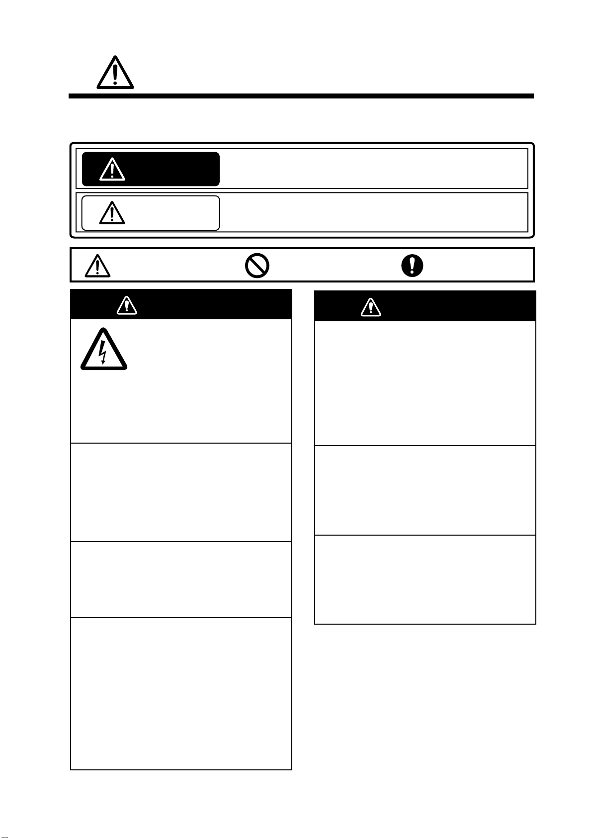
SAFETY INSTRUCTIONS
WARNING
WARNING
The operator and installer must read the applicable safety instructions before attempting to
install or operate the equipment.
Indicates a potentially hazardous situation which, if not avoided,
WARNING
CAUTION
Warning, Caution
could result in death or serious injury.
Indicates a potentially hazardous situation which, if not avoided,
can result in minor or moderate injury.
Prohibitive Action
Mandatory Action
ELECTRICAL SHOCK HAZARD
Do not open the equipment
Turn off the power at the switchboard
before beginning the installation.
Connect to a dedicated breaker in the power
distributor.
Fire or electrical shock can result if the
power is left on.
Do not install the equipment where it
may get wet from rain or water splash.
Water in the equipment can result in fire,
electrical shock or damage the equipment.
unless totally familiar with
electrical circuits and
service manual.
Only qualified personnel
should work inside the
equipment.
Be sure that the power supply is
compatible with the voltage rating of
the equipment.
Connection of an incorrect power supply
can cause fire or damage the equipment.
The voltage rating of the equipment
appears on the label above the power
connector.
Install the transducer according
to the installation instructions.
Failure to install the transducer correctly
may result in water leakage and damage to
the ship's hull.
For wooden or FRP vessel using a steel
tank, attach a zinc plate to the hull to
prevent electrolytic corrosion.
Electrolytic corrosion can, in the worst
case, result in loss of the transducer.
Be sure no water leaks in at the transducer mounting location.
Water leakage can sink the vessel. Also,
confirm that the transducer will not loosen
by ship's vibration. The installer of the
equipment is solely responsible for the
proper installation of the equipment.
FURUNO will assume no responsibility for
any damage associated with improper
installation.
i
Page 4
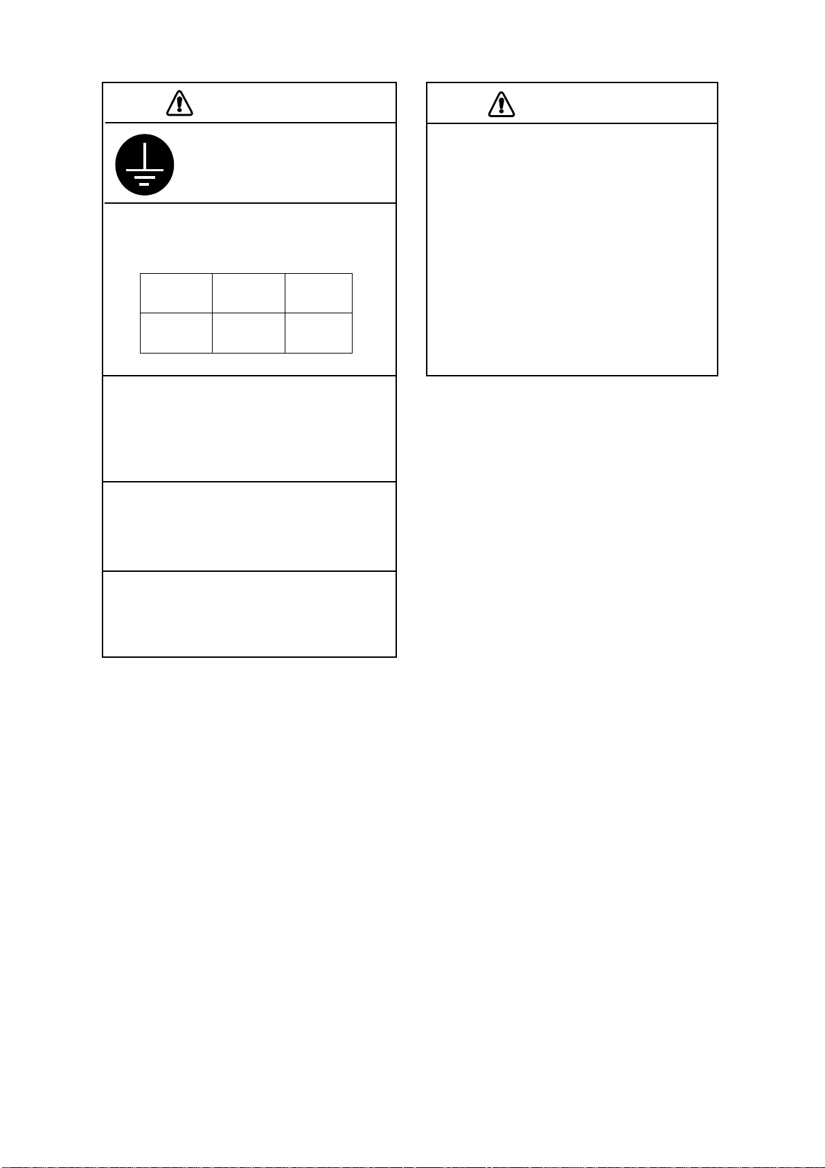
CAUTION
Ground the equipment to
CAUTION
prevent mutual interference.
The transducer cable must he handled
carefully, following the guidelines
below.
Observe the following compass safe
distances to prevent interference to a
magnetic compass:
Standard
compass
CV-1150
Do not allow warm water or any other
liquid other than seawater or freshwater
to contact the transducer.
The transducer may become damaged.
Do not turn on the power when the
transducer is in air.
The transducer may become damaged.
Do not install the transducer where
noise or air bubbles is present.
0.75 m 0.50 m
Steering
compass
Performance will be affected.
• Keep fuels and oils away from the
cable.
• Locate the cable where it will not be
damaged.
• The cable sheath is made of chloro-
phrene or polychloride vinyl, which
are easily by damaged plastic solvents
such as toulene. Locate the cable
well away from plastic solvents.
ii
Page 5
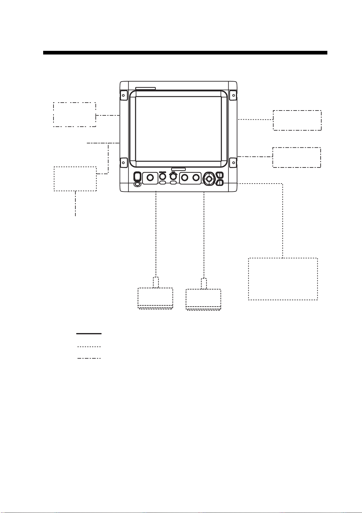
SYSTEM CONFIGURATION
Display unit
CV-1150
NavNet 3D
12-24 VDC
Rectifier
PR-62
100/110/115/
220/230 VAC
1㱢, 50/60 Hz
High
Navigator
Satellite
compass
Temperature sensor
T-02MSB, etc.
Speed/temp sensor
ST-02MSB, etc.
Low
Transducer
: Standard supply
: Optional supply
: Local supply, External device
Transducer
iii
Page 6
EQUIPMENT LISTS
Standard supply
Name Type Code No. Qty Remarks
Display Unit CV-1150 - 1
Spare Parts SP02-05401 001-032-550 1 set
Accessories FP02-05700 000-011-976 1 set
Installation Materials CP02-08301 001-032-560 1 set
Option
Name Type Code No. Remarks
See back of this manual.
Transducer
Thru-hull pipe -
Ta nk -
Cable MJ-A6SPF0003-050C 000-154-054-10 one end 6 pin, 5 m, for navigator
Water temperature
sensor
Speed/Temperature sensor
Rectifier PR-62 000-013-484 100 V AC
See next pages.
CO-SPEVV-SBC
2Px0.2SQ LF
T-02MSB 000-040-040 Thru-hull type
T-02MTB 000-040-026 Transom type
T-03MSB 000-040-027 Thru-hull type
ST-02MSB 000-137-986-01 Thru-hull type
ST-02PSB 000-137-987-01 Thru-hull type
000-111-680-10 5 m
000-120-792-10 10 m
000-120-793-10 15 m
000-013-485 110 V AC
000-013-486 220 V AC
-
000-013-487 230 V AC
iv
Page 7

Combination of transducer, thru-hull pipe and tank
Output
(W)
1k/1k 28/50 Steel 28F-8
1k/2k 28/200 Steel 28F-8
2k/2k 28/50 Steel 28F-18
Frequency
(kHz)
28/88 Steel 28F-8
50/88 Steel 50B-9B
50/200 Steel 50/200-1T
50/200 Steel 50B-9B
88/200 Steel 88B-8
28/82 Steel 28F-18
28/88 Steel 28F-18
28/200 Steel 28F-18
38/200 Steel 38BL-9HR
50/82 Steel 50B-12
50/88 Steel 50B-12
50/200 Steel 50B-12
50/200 Steel 50BL-12
82/200 Steel 82B-35R
88/200 Steel 88B-10
28/107 Steel 28F-18
Ship type Transducer Thru-hull pipe Tank
FRP
FRP - -
FRP - -
FRP - T-603F
FRP - -
FRP - -
FRP - -
FRP TRB-1100(2) T-634-F
FRP TRB-1100(2) T-636-F
FRP TRB-1100(2) T-636-F
FRP TRB-1100(2) T-638-F
Steel 28BL-6HR
FRP TRB-1100(2) T-693-F
FRP TRB-1100(2) T-693-F
FRP TRB-1100(2) T-643-F
FRP TRB-1100(2) T-643-F
FRP TRB-1100(2) T-645-F
Steel 50BL-12HR
FRP TRB-1100(2) T-693-F
FRP TRB-1100(2) T-693-F
FRP TRB-1100(2) T-649-F
FRP TRB-1100(2) T-649-F
FRP TRB-1100(2) T-636-F
50B-9B
88B-8
88B-8
50/200-1ST
200B-8/8B
200B-8/8B
200B-8/8B
50B-12
82B-35R
88B-10
200B-8/8B
200B-8/8B
200B-8/8B
82B-35R
88B-10
200B-8/8B
200B-8/8B
200B-8/8B
200B-8/8B
200B-8/8B
100B-10H
TWB-6000(2) T-656
-
TWB-6000(2) T-657
TWB-6000(2) T-658
TFB-5000(1) T-603
TWB-6000(2) T-657
TWB-6000(2) T-658
TWB-6000(2) T-659
TFB-7000(2) T-634
TFB-7000(2) T-636
TFB-7000(2) T-636
TFB-7000(2) T-638
TFB-7000(2) T-693
TFB-7000(2) T-693
TFB-7000(2) T-643
TFB-7000(2) T-643
TFB-7000(2) T-645
TFB-7000(2) T-693
TFB-7000(2) T-693
TFB-7000(2) T-649
TFB-7000(2) T-649
TFB-7000(2) T-636
-
v
Page 8

Output
(W)
2k/3k 28/150 Steel 28F-18
3k/2k 68/200 Steel 68F-30H
3k/3k 28/38 Steel 28BL-12HR
Frequency
(kHz)
50/107 Steel 50B-12
50/150 Steel 50B-12
107/200 Steel 100B-10R
28/50 Steel 28BL-12HR
28/88 Steel 28BL-12HR
28/150 Steel 28BL-12HR
28/200 Steel 28BL-12HR
38/50 Steel 38BL-15HR
38/88 Steel 38BL-15HR
Ship type Transducer Thru-hull pipe Tank
FRP TRB-1100(2) T-637-F
FRP TRB-1100(2) T-643-F
FRP TRB-1100(2) T-644-F
FRP TRB-1100(2) T-647-F
FRP TRB-1100(2) T-649-F
FRP TRB-1100(2) T-681-F
Steel 28F-24H
FRP TRB-1100(2) T-681-F
FRP TRB-1100(2) T-681-F
Steel 28BL-12HR
FRP TRB-1100(2) T-681-F
Steel 28F-24H
FRP TRB-1100(2) T-696-F
Steel 28F-24H
FRP TRB-1100(2) T-681-F
Steel 28F-24H
FRP TRB-1100(2) T-681-F
FRP TRB-1100(2) T-682-F
Steel 28F-24H
FRP TRB-1100(2) T-682-F
FRP TRB-1100(2) T-683-F
Steel 28F-24H
FRP TRB-1100(2) T-683-F
FRP TRB-1100(2) T-683-F
Steel 28F-24H
FRP TRB-1100(2) T-683-F
FRP TRB-1100(2) T-681-F
Steel 38BL-15HR
FRP TRB-1100(2) T-681-F
FRP TRB-1100(2) T-682-F
150B-12H
100B-10R
150B-12R
200B-8/8B
200B-8/8B
38BL-15HR
38BL-15HR
50BL-24HR
50F-24H
50BL-24H
50BL-24HR
50F-24H
88F-126H
88F-126H
150B-12H
150B-12H
200B-12H
200B-12H
50BL-24HR
50F-24H
88F-126H
TFB-7000(2) T-637
TFB-7000(2) T-643
TFB-7000(2) T-644
TFB-7000(2) T-647
TFB-7000(2) T-649
TFB-7000(2) T-681
TFB-7000(2) T-681
TFB-7000(2) T-681
TFB-7000(2) T-681
TFB-7000(2) T-696
TFB-7000(2) T-681
TFB-7000(2) T-681
TFB-7000(2) T-682
TFB-7000(2) T-682
TFB-7000(2) T-683
TFB-7000(2) T-683
TFB-7000(2) T-683
TFB-7000(2) T-683
TFB-7000(2) T-681
TFB-7000(2) T-681
TFB-7000(2) T-682
vi
Page 9

Output
(W)
3k/3k 38/150 Steel 38BL-15HR
1k 28 Steel 28F-8 TFB-5000(1) T-604
Frequency
(kHz)
38/200 Steel 38BL-15HR
50/88 Steel 50BL-24H
50/150 Steel 50BL-24HR
50/200 Steel 50BL-24H
68/150 Steel 68F-30H
68/200 Steel 68F-30H
88/150 Steel 88F-126H
88/200 Steel 88F-126H
50 Steel 50B-6/6B TFB-5000(1) T-605
68 Steel 68F-8H TFB-5000(1) T-621
88 Steel 88B-8 TFB-5000(1) T-606
200 Steel 200B-5S TFB-5000(1) T-605
Ship type Transducer Thru-hull pipe Tank
TFB-7000(2) T-683
FRP TRB-1100(2) T-683-F
FRP TRB-1100(2) T-683-F
FRP TRB-1100(2) T-697-F
Steel 50BL-24HR
FRP TRB-1100(2) T-682-F
Steel 50F-24H
FRP TRB-1100(2) T-682-F
FRP TRB-1100(2) T-683-F
Steel 50F-24H
FRP TRB-1100(2) T-683-F
FRP TRB-1100(2) T-695-F
Steel 50BL-24HR
FRP TRB-1100(2) T-683-F
Steel 50F-24H
FRP TRB-1100(2) T-683-F
FRP TRB-1100(2) T-646-F
FRP TRB-1100(2) T-646-F
FRP TRB-1100(2) T-685-F
FRP TRB-1100(2) T-685-F
FRP TRB-1000(1) T-604-F
FRP TRB-1000(1) T-605-F
Steel 50B-9B TFB-5000(1) T-603
FRP TRB-1000(1) T-603-F
FRP TRB-1000(1) T-621-F
FRP TRB-1000(1) T-606-F
FRP TRB-1000(1) T-605-F
150B-12H
TFB-7000(2) T-683
200B-12H
TFB-7000(2) T-697
88F-126H
TFB-7000(2) T-682
88F-126H
TFB-7000(2) T-682
88F-126H
TFB-7000(2) T-683
150B-12H
TFB-7000(2) T-683
150B-12H
TFB-7000(2) T-695
200B-12H
TFB-7000(2) T-683
200B-12H
TFB-7000(2) T-683
200B-12H
TFB-7000(2) T-646
150B-12H
TFB-7000(2) T-646
200B-12H
TFB-7000(2) T-685
150B-12H
TFB-7000(2) T-685
200B-12H
vii
Page 10

Output
(W)
2k 28 Steel 28F-18 TFB-5000(1) T-612
3k 28 Steel 28F-24H TFB-4000(1) T-616
Frequency
(kHz)
38 Steel 38BL-9HR TFB-5000(1) T-702
50 Steel 50B-12 TFB-5000(1) T-611
82 Steel 82B-35R TFB-5000(1) T-609
88 Steel 88B-10 TFB-5000(1) T-609
200 Steel 200B-8/8B TFB-5000(1) T-608
38 Steel 38BL-15HR TFB-4000(1) T-616
50 Steel 50F-24H TFB-4000(1) T-616
68 Steel 68F-30H TFB-5000(1) T-614
88 Steel 88F-126H TFB-4000(1) T-618
107 Steel 100B-10R TFB-5000(1) T-609
150 Steel 150B-12H TFB-5000(1) T-615
200 Steel 200B-12H TFB-5000(1) T-615
Ship type Transducer Thru-hull pipe Tank
FRP TRB-1000(1) T-612-F
Steel 28BL-6HR TFB-5000(1) T-702
FRP TRB-1000(1) T-702-F
FRP TRB-1000(1) T-702-F
FRP TRB-1000(1) T-611-F
Steel 50BL-12 TFB-5000(1) T-702
FRP TRB-1000(1) T-702-F
Steel 50BL-12HR TFB-5000(1) T-702
FRP TRB-1000(1) T-702-F
FRP TRB-1000(1) T-609-F
FRP TRB-1000(1) T-609-F
FRP TRB-1000(1) T-608-F
FRP TRB-1000(1) T-616-F
Steel 28BL-12HR TFB-4000(1) T-616
FRP TRB-1000(1) T-616-F
FRP TRB-1000(1) T-616-F
FRP TRB-1000(1) T-616-F
Steel 50BL-24HR TFB-4000(1) T-616
FRP TRB-1000(1) T-616-F
Steel 50BL-24H TFB-4000(1) T-694
FRP TRB-1000(1) T-694-F
FRP TRB-1000(1) T-614-F
FRP TRB-1000(1) T-618-F
FRP TRB-1000(1) T-609-F
FRP TRB-1000(1) T-615-F
FRP TRB-1000(1) T-615-F
viii
Page 11
1. MOUNTING
WARNING
Do not apply paint, anti-corrosive sealant
or contact spray to coating or plastic
parts of the equipment.
Those items contain organic solvents that
can damage coating and plastic parts,
especially plastic connectors.
1.1 Display Unit
Turn off the power at the switchboard
before beginning the installation.
NOTICE
Fire or electrical shock can result if the
power is left on.
Mounting considerations
• Locate the unit out of direct sunlight.
• The operator should face the bow while viewing the display screen.
• Select a location where the display screen can be easily observed while operating the control
panel.
• Leave sufficient space around the unit for maintenance and servicing. Recommended maintenance space appears in the outline drawing at the back of this manual.
• Observe the compass safe distances on page ii to prevent deviation of a magnetic compass.
The display unit can be mounted on the tabletop or on the panel (flush mounting). Mount the unit,
referring to the outline drawing at the back of this manual.
1.2 Transducer
The performance of the echo sounder depends upon the transducer position. A place least affected by air bubbles should be selected since turbulence blocks the sounding path. Further, select a
place least influenced by engine noise. It is known that air bubbles are fewest at the place where
the bow first falls and the next wave rises, at usual cruising speed.
Note: The face of the transducer must be facing the sea bottom in normal cruising trim of the boat.
1
Page 12

1.3 Water Temperature/ Speed Sensor
Transom mount water temperature sensor T-02MTB
• Fix the cable at a convenient location on the transom with the cable clamp.
• When the cable is led through the transom board, make a hole of approx. 17 mm in diameter to
pass the connector. After passing the cable, seal the hole with a sealing compound.
D>500
How to mount transom mount water temperature sensor T-02MTB
D
5X20
Flush with hull bottom
[Units: mm]
2
Page 13

Thru-hull mount water temperature sensor T-02MSB, T-03MSB
Select a suitable mounting location considering the following points:
• Select a mid boat flat position. The sensor does not have to be installed perfectly perpendicular; however, the location should not be such that the transducer may be damaged when the
boat is dry-docked.
• Locate away from equipment which gives off heat.
• Locate away from drain pipes.
• Select a location where vibration is minimal.
T-02MSB T-03MSB
Sensor Holder
cable
8 m
Sensor
cable
8 m
Locknut
Washer
Gasket
Locknut
Locknut
φ21 mm
M20
70
φ42
Mounting procedure
1. Drill a hole of 21 mm in diameter in
the mounting location.
2. Pass the sensor cable through the
hole.
3. Pass gasket, washer and locknut
onto cable in that order.
4. Coat the sensor flange with high
quality sealant and then fasten the
sensor with the locknut.
(Torque: max. 59N·m)
5. Launch the boat to check for water
leakage around the sensor.
Coat with
sealant.
Washer
Gasket
φ25 mm
Coat with
sealant.
Plate thickness within
Holder Guide
Mounting procedure
1. Drill a hole of 25 mm in diameter in the mounting
location.
2. Coat holder guide with high quality sealant, and
pass gasket, washer and locknut onto holder
guide in that order and then tighten the locknut.
3. Set the sensor holder to the holder guide from
inside the boat and then tighten the locknut.
4. Launch the boat to check for water leakage
around the sensor.
25 mm
Assembling thru-hull water temperature sensor T-02MSB, T-03MSB
3
Page 14

Through-hull mount water temperature/speed sensor ST-02MSB,
ST02-PSB
Select a suitable mounting location considering the following:
• Select a mid-boat flat position. The sensor does not have to be installed perfectly perpendicular. The sensor must not be located where it might get damaged in dry-docking operation.
• Select a place apart from equipment generating heat.
• Select a place in the forward direction viewing from the drain hole, to allow for circulation of
cooling water.
• Select a place free from vibration.
1. Dry-dock the boat.
2. Make a hole of approx. 51 mm diameter.
3. Unfasten locknut and remove the flange of the sensor.
4. Apply high-grade sealant to the flange of the sensor.
5. Pass the sensor casing through the hole.
6. Face the notch on the sensor toward boat's bow and tighten the flange.
7. Set the sensor section to the sensor casing and tighten the locknut.
8. Launch the boat and check for water leakage around the sensor.
Locknut
Face "notch"
toward bow.
Flange nut
51
123
Coat with
silicone sealant.
Brim
φ77
Water temperature/speed sensor ST-02MSB, ST-02PSB
4
Page 15

2. WIRING
2.1 Interconnection
Refer to the interconnection diagram at the back of this manual for detailed information.
Display unit rear panel
(connector cover removed)
IV-2.0sq
NavNet 3D
Speed/
Water temperature
sensor
Rectifier
PR-62
DPYCY-1.5
100/110/115/
220/230 VAC
φ
, 50/60 Hz
1
DPYCY-1.5
CO-SPEVV-SBC 2Px0.2SQ
TTYCS-1
Satellite
compass
12-24 VDC
(Connect to a dedicated
breaker in the power
distributor.)
MJ-A6SPF0003-050C
Navigator
High
Transducer
*
Transducer
Grounding wire:
As short as possible
Low
*
: Standard supply
: Option
: Local supply, External device
Wiring diagram for FCV-1150
5
*: This unit cannot accept transducers of
53 to 65 kHz, 111 to 139 kHz and 171
to 183 kHz.
Page 16

2.2 Wiring Standard Equipment
A
Power cable
This video sounder is designed to be powered with 12-24 VDC power. Use the cable DPYCY-1.5
(Japan Industry Standard) or equivalent.
6
Approx. 70
3
30
DPYCY-1.5
Armor
Sheath
Conductor
S = 1.5 mm
Ǟ = 1.56 mm
(AWG16)
2
Climp-on lug
FV2-M4
Sheath
Vinyl tape
Clamp armor with cable clamp.
Armor
Sheath
Ǟ = 13.7 mm
Power cable DPYCY-1.5 (JIS cable)
Transducer
Separate the transducer cable well away from power cables to prevent interference. Connect the
cable to the transducer port (for high frequency and/or low frequency) at the rear of the display
unit. Fabricate the cable as below.
Approx. 100
Shield
Extract cores from here and cut inner materials.
Sheath
Shield
6
ttach WAGO
connector.
(See next page.)
Vinyl tape
30
Wrap shield around sheath 30 mm and cut
excess shield. Clamp here with cable clamp.
Vinyl tape
Note: Never connect the shield to #2 of
[Composite transducer]
the WAGO connector.
BLK, RED: L side
BLU, GRN: H side
Fabrication of transducer cable
Note: FCV-1150 cannot accept the transducers of 53 - 65 kHz, 111 to 139 kHz and 171 - 183 kHz.
6
Page 17

NMEA port
Connect a GPS navigator, etc. to NMEA port J2 #1 to #4. You can connect two sensors (for example, GPS receiver GP-310B and smart sensor). One connects to NMEA port J2 #1 to #2 and
the other connects to the NMEA port J2 #3 to #4. A satellite compass can be connected to NMEA
port J2 #5 to #6.
Cable connected to NMEA port: Furuno cable MJ series
Approx. 30
Shield
6
Cut shield here and
solder vinyl wire.
Cable connected to NMEA port: Furuno cable CO-SPEVV-SB-C
6
Cable connected to NMEA port: JIS cable TTYCS-1Q
6
Approx. 80
Approx. 80
Cut shield here and
solder vinyl wire.
Vinyl tape
Clamp vinyl sheath with cable clamp.
3
30
Armor
Clamp armor with cable clamp.
3
30
Sheath
TTYCS-1Q (Four cores twisted)
Cut shield here and
solder vinyl wire.
Vinyl tape
Sheath
Armor
Vinyl tape
Ǟ = 11.3 mm
Clamp vinyl sheath with cable clamp.
7
Shield
Conductor
S = 0.75 mm
Ǟ = 1.11 mm
(AWG18)
Armor
Sheath
2
Page 18

WAGO connector (for transducer and NMEA port)
Press
Opener (attached inner side of shield cover).
1. Twist conductors
2. Insert opener and press it down.
3. Insert core to hole.
Twist.
Core
4. Release opener.
5. Pull the core to confirm to make sure it is
tightly fastened.
2.3 Input/Output Sentences
Input sentences
Sentence Data Remarks
BWC Range/bearing to waypoint
GGA Time, position GPS position
GLC GRI, Time difference Loran C
GLL Latitude and longitude GPS position
GNS GNSS position fixing
GTD Time difference Loran C
HDG Ship's heading, deviation, variation
HDT True heading
MDA Weather information
MTW Water temperature
MWV Wind direction, wind speed (true or apparent)
RMA Latitude and longitude, TD, ground speed and course Loran C
RMB Recommended minimum navigation information
RMC Latitude and longitude, speed over ground and course over ground GPS
VHW True/magnetic bearing, speed through water
VTG Speed over ground and course over ground
XTE Cross track error
att Roll, pitch
hve Heaving data
req Output request for specified attribute
8
Page 19

Output sentences
Sentence Data Remarks
DBT Depth below transducer Ver. 1.5
DPT Depth below transducer and offset Ver. 2.0
MTW Water temperature
TLL Marker line position Ver. 2.0
SDmrk Mark position (L&L) and its additional data
VHW Speed thru water
RMB Navigation information
dat Data of specified attribute (device name)
DBS Depth below sea surface
With connection of water
temperature sensor
9
Page 20

3. INITIAL SETTING
This chapter provides the information necessary for initial setup of the equipment. First turn on the
power and set display language. Then, set transducer used, by model number (FURUNO transducer only) or by specifications.
3.1 Language Setting
1. Press [ /BRILL] key to turn on the power. The following display appears.
Language setting screen
2. Press T or S to select English as an example, and then press the ENTER key to set. The unit
setting screen appears.
Unit setting screen
3. Set the units of measurement if necessary. For example, to set the distance unit, press T to
select “Distance Unit” and press the ENTER key. The list of selectable distance units is dis-
played.
10
Page 21

4. Press T or S to select necessary unit and then press the ENTER key to set.
CAUTION
• Depth: m, ft, fa, pb, HR (Japanese unit)
• Temp: °C, °F
• Speed: kt, km/h, mph
• Wind: kt, km/h, mph, m/h
• Distance: nm, km, sm
5. Press the MENU key. The following message appears.
6. Press any key. The transducer setting screen appears. Proceed to next section.
3.2 Transducer Data
Set the transducer model number
properly.
Wrong transducer setting can damage the
transducer and void the warranty.
Entering transducer data by transducer model
The following table shows the transducers programmed in the FCV-1150.
Type Output (kW) Tap Type Output (kW) Tap
28F-8 1 B 50BL-24HR 3 D
28BL-6HR 2 A 50F-24H 3 B
28F-18 2 B 68F-8H 1 A
28BL-12HR 3 A 68F-30H 3 B
28F-24H 3 D 82B-35R 2 E
38BL-9HR 2 B 88B-8 1 D
38BL-15HR 3 D 88B-10 2 C
50B-6B 1 A 88F-126H 3 E
*
50/200-IT
50/200-1ST (50 kHz) 1 B 150B-12H 3 C
(50 kHz)
1 B 100B-10R 3 E
50B-9B 1 A 200B-5S 1 D
50B-12 2 A
50BL-12 2 A 50/200-1ST (200 kHz) 1 A
50BL-12HR 2 B 200B-8B 2 C
50BL-24H 3 D 200B-12H 3 C
*: for ACCU-FiSH (Fish information display)
50/200-1T
*
(200 kHz)
1C
11
Page 22

Note: The “XDCR Setting” dialog box (see the illustration that follows step 1 below) only appears
when turning on the power after installation, after setting the desired language and the units of
measurement (see section 3.1). To open the “XDCR Setting” dialog box after completion of the
transducer setting, turn off the power, then turn on the power while pressing any key. Release the
key after the "XDCR Setting" dialog box appears.
1. At the transducer setting screen, confirm that "XDCR Select" is set to "XDCR Type" (default
setting).
Transducer setting screen
2. If a high frequency transducer is fitted, press T to select “HF Connection” and then press the
ENTER key.
Connected
Not connected
3. Press S to select “Connected” and then press the ENTER key.
4. Press T to select “Freq” and then press the ENTER key.
12
Page 23

5. Press T or S to select the transducer frequency and then press the ENTER key.
6. Press S to select “Transducer” and then press the ENTER key. The list of programmed transducers appears.
200B-5S
50/200-1T
50/200-1ST
200B-8B
200B-12H
7. Press T to select transducer connected and then press the ENTER key.
8. Jot down the alphabet which appears on the “TAP” line. You may need to change the tap setting at the rear of the display unit depending on the transducer type which is connected. For
details, see below.
9. If a low frequency transducer is fitted, repeat steps 2 to 8.
Note: Leave the “Tx Power” setting at “Auto”.
10.To connect to the NavNet 3D system, press T to select “NavNet Mode” and then press the
ENTER key. Select “On” and press the ENTER key.
The following program versions can be connected to the FCV-1150.
MFD8/12: 1950055-02.01 and later
MFDBB: 1950064-02.01 and later
(Example: 200 kHz)
11.Press and hold down the [ /BRILL] key to turn off the power.
Tap setting
Set the tap according to the alphabet shown when you selected transducer type.
Display unit rear panel
(connector cover removed)
Tap setting plug
(for high frequency)
Tap setting plug
(for low frequency)
Common point
E D C B A
jumper
connection
Set this side according to indication.
13
Page 24

Entering transducer data by transducer specifications
To connect the transducers which are not programmed, do as follows:
Note: The transducers of 53 - 65 kHz, 111 to 139 kHz and 171 - 183 kHz cannot be connected to
the FCV-1150 because of noise.
1. At the XDCR Setting dialog box, select “XDCR Select” and press the ENTER key.
The following screen appears.
XDCR Type
Manual
2. Press T to select “Manual”, and then press the ENTER key.
3. If a high frequency transducer is fitted, press T to select “HF Connection” and then press the
ENTER key.
Connected
Not connected
4. Press S to select “Connected” and then press the ENTER key.
5. Press T to select “Freq” and then press the ENTER key.
--- kHz
6. Press T or S to set the value for the frequency which is connected and then press the
ENTER key.
7. Press T to select “Band width” and then press the ENTER key.
8. Press T or S to set the value for the band width and then press the ENTER key. If the band
width is not entered manually, it is automatically set to 1/10 of the transducer frequency.
9. If a low frequency transducer is fitted, repeat steps 3 to 8.
Note: Leave the “Tx Power” at “Auto”.
10.Press and hold down the [ /BRILL] key to turn off the power.
3.3 Speed/Water Temperature Sensor Calibration
If the optional speed and/or water temperature sensor is connected, set up as follows:
1. Turn on the power and press the MENU key.
The main menu and sub-menu appears.
2. Press T to select “System” and “Club” and then press the ENTER key.
14
Page 25

3. Press T to select "Temp" and then press the ENTER key.
Temperature calibration screen
4. Press T or S to set the value for the temperature calibration and then press the ENTER key.
For example, if the temperature indication is 2.5°C higher than the actual value,
set “-2.5°C”.
5. To calibrate the speed value, press T to select "Speed(STW)" and then press the ENTER
key.
6. Press T or S to set the value for the speed calibration and then press the ENTER key.
For example, if the speed indication is 5% lower than the actual value, set +5%.
7. To close the menu, press the MENU/ESC key twice.
15
Page 26

3.4 NMEA Port Setting
If a GPS navigator and/or other sensor are connected, set up as follows.
1. Press the MENU key.
2. Press T to select "System" and "NMEA" and then press the ENTER key.
NMEA setting menu
3.Press T to select the item to set and then press the ENTER key.
4.Press T or S to select an appropriate one and then press the ENTER key.
Description for each item of the NMEA menu
NMEA0183: Choose NMEA0183 version of navigation equipment connected to the NMEA port,
among Ver. 1.5, Ver. 2.0 or Ver. 3.0. "SPECIAL" is for use with a navigator whose baud rate is
600 bps.
NMEA Port: The NMEA terminals in the NMEA port can function as input ports or input/output
port. Change the setting to "In/In" when connecting GP-310B/320B and a wind sensor. When connecting the GP-320B and a wind sensor, first turn on "WAAS Setup" and then select "In/In" as the
NMEA Port setting.
• In/Out: NMEA port J2 #1 & #2 is output port and J2 #3 & #4 is input port.
• In/In: NMEA port J2 #1 & #2 changes to input port. (Available with connection of the GP-310B/
320B and a wind sensor.)
NMEA Output: Set the output data sentences.
• Off: Outputs the "output data sentences" (see page 9).
• On: Outputs the "output data sentences" of FCV-1150 and sentences which are input from
other equipment.
16
Page 27

WAAS Setup: Choose how to use the WAAS signal when connecting with a WAAS receiver, for
example GP-320B. The message types (WAAS-00 to WAAS-27) are used as WAAS correction.
Choose WAAS-00 to enable WAAS.
Note: Currently, WAAS is only available in North America, and Japan and it is in the developmental stage in Europe and Japan. During the developmental phase the reliability and availability of
the WAAS signal cannot be guaranteed. Therefore, any position data should be verified against
other sources to confirm reliability. This function is available only when In/Out is selected at NMEA
Port.
TLL Output: Output the position specified by the MARK key to the plotter connected.
• Off: Does not output latitude/longitude.
• TLL: Outputs latitude/longitude.
• FURUNO-TLL: Outputs latitude/longitude, depth and water temperature. This requires
FURUNO-TLL enabled device.
Port Monitor: Port Monitor provides information for the data sentences input from the NMEA port.
Press the ENTER key to display the latest data sentence information. To display this information
on the Port 2 screen when two sensors are connected, set NMEA Port on the NMEA menu to In/In.
3.5 Heaving Setting
For the heaving feature to function correctly, set the distance between satellite compass antenna
(GPS sensor) and transducer as follows.
1. Press the MENU key to display the main menu.
2. Press T to select “Stabi” and then press the ENTER key.
3. Press T or S to select “Stabilization” and then press the ENTER key.
4. Press T to select “On” and then press the ENTER key.
5. Press T to select “Sensor” and then press the ENTER key.
SC50/110
SC30
6. Select the type of satellite compass connected and then press the ENTER key.
17
Page 28

7. Press T to select “Stabi. Area“ and then press the ENTER key.
8. Press T or S to select desired Stabi. Area and then press the ENTER key.
When heaving exceeds the value set here, stabilization is stopped and the stabilizer icon
at the top of the screen disappears. However, the heaving mode is kept “On“. When heaving
is once again less than the value set here, stabilization is restarted and the stabilizer icon
reappears.
9. Set the distance between transducer(s) and antenna unit (or sensor) of the satellite compass
as follows.
TD fore-aft: Set the distance from antenna unit to the transducer in fore-aft direction. When
the transducer is located on the fore side, set a positive value.
TD port-stbd: Set the distance from antenna unit to the transducer in port-starboard direction.
When the transducer is located on the starboard side, set a positive value.
ANT-TD height: Set the distance from the transducer to the antenna unit in the vertical direction.
Note: For the heaving feature, set the output of satellite compass SC-50/110/30 as follows.
SC-50/110
(DATA OUT menu)
Sentence ATT, HVE ATT, HVE
Baud rate 38400 BPS 38400 BPS
Cycle 25 ms 25 ms
Format IECED1 -
SC-30
(Set IF-NMEASC)
18
Page 29

APPENDIX TRANSDUCER 82B-35R
The 82B-35R is a transducer with wide bandwidth of 65 kHz-110 kHz. It is constructed to provide
protection against slamming.
Transducer, thru-hull pipe and tank list
Frquency
(kHz)
28/82 28F-18/82B-35R Steel T-636
50/82 50F-8G/82B-35R Steel T-636
82/200 82B-35R/200B-8/
Transducer Hull
Material
FRP T-636F
FRP T-636F
50B-12/82B-35R Steel T-643
FRP T-643F
Steel T-649
200B-8B/200B-8N
FRP T-649F
(Code No.)
(000-015-813)
(000-015-814)
(000-015-813)
(000-015-814)
(000-015-821)
(000-015-822)
(000-015-833)
(000-015-834)
Tank
Fasten inside
hull (Code No.)
TWB-6000 (2)
(000-015-207)
TRB-1100 (2)
(000-015-218)
TWB-6000 (2)
(000-015-207)
TRB-1100 (2)
(000-015-218)
TWB-6000 (2)
(000-015-207)
TRB-1100 (2)
(000-015-218)
TWB-6000 (2)
(000-015-207)
TRB-1100 (2)
(000-015-218)
Fasten outside
hull (Code No.)
TFB-7000 (2)
(000-015-209)
-
TFB-7000 (2)
(000-015-209)
-
TFB-7000 (2)
(000-015-209)
-
TFB-7000 (2)
(000-015-209)
-
Connection
Connect the 82B-35R transducer to either the "HF" or "LF" connector, referring to page S-1.
Tap Setting
Referring to page 13, set the tap to E.
AP-1
Page 30

Setting for dual frequency transmitting
1. Set the XDCR SELECT menu as follows (see page 12 and 13).
Setting for “HF” connection
Setting for “LF” connection
2. Press the [PWR] key to turn the power off, and turn it on again.
3. Press the MENU key to show the menu.
4. Select [Sounder] and press the ENTER key.
5. See the section "1.20.1 Sounder menu" in the Operator's Manual for how to set "Freq Choice"
and "Freq Control" for high and low frequencies.
AP-2
Page 31

1
A-1
1
1
1
1
1/1
02GD-X-9851 -2
NAME OUTLINE Q'TYDESCRIPTION/CODE №
100-342-010-10
02-157-1302-0
000-167-734-1*
MLG-23780-*
C22-00702-* ワ/エイ
**
000-167-736-1*
000-167-732-1*
IM*-23780-*
**
000-167-728-1*
OM*-23780-*
02GD-X-9851
Fマウントヨウスポンジ
FCV-1150-J/E
図書 DOCUMENT
FLUSH MOUNTING SPONGE
1
**
000-011-708-00
CV-1150
操作要領書(タゲン)
OPERATOR'S GUIDE
フラッシュマウント型紙
4
SP02-05401
000-157-493-10
FGMB 125V 7A PBF
FLUSH MOUNTING TEMPLATE
1
FP02-05700
02-155-1082-1
装備要領書
INSTALLATION MANUAL
CP02-08301
100-332-651-10
取扱説明書
OPERATOR'S MANUAL
2
000-157-229-10
FV2-M4
1
000-147-417-10
734-230
5
000-162-608-10
5X20 SUS304
1
000-165-800-10
231-131
型式/コード番号が2段の場合、下段より上段に代わる過渡期品であり、どちらかが入っています。 なお、品質は変わりません。
TWO TYPES AND CODES MAY BE LISTED FOR AN ITEM. THE LOWER PRODUCT MAY BE SHIPPED IN PLACE OF
THE UPPER PRODUCT. QUALITY IS THE SAME.
PACKING LIST
NAME OUTLINE Q'TYDESCRIPTION/CODE №
ユニット UNIT
指示器
DISPLAY UNIT
予備品 SPARE PARTS
ヒューズ
FUSE GLASS TUBE TYPE
付属品 ACCESSORIES
フィルタークリーナー
LCD CLEANING CLOTH
工事材料 INSTALLATION MATERIALS
圧着端子
CRIMP-ON LUG
操作レバー
TERMINAL OPENER
+トラスタッピンネジ 1シュ
SELF-TAPPING SCREW
操作レバー
TERMINAL OPENER
(略図の寸法は、参考値です。 DIMENSIONS IN DRAWING FOR REFERENCE ONLY.)
Page 32

Oct.4'07R.Esumi
D-1
Page 33

Oct.3'07R.Esumi
D-2
Page 34

43
S-1
相互結線図
パソコン(保守用)
PC FOR MAINTENANCE
または OR
マルチファンクションディスプレイ
MULTI-FUNCTION DISPLAY
MFD8/12/BB
カラー魚群探知機
TRANSDUCER
FCV-1150
TITLE
名称
TD_LF-COLD
3
NC
2
TD_LF-HOT
1
*2
8m
T-02MSB
T-03MSB
T-02MTB
水温センサー
TEMP. SENSOR
J5
TD_HF-COLD
3
NC
2
TD_HF-HOT
1
J4
RED
BLK
GRN
BLU
アカ
クロ
ミドリ
アオ
10m(1ST:15m)
50/200-1T
50/200-1ST
*2
送受波器
INTERCONNECTION DIAGRAM
COLOR LCD SOUNDER
NAME
P
+12V
12V_0V
10
6
NC
*2
10m
1B1 02P6352
ST-02MSB
ST-02PSB
TD_LF-COLD
NC
TD_LF-HOT
J5
LF
TD_HF-COLD
NC
TD_HF-HOT
J4
HF
TEMP/SPEED SENSOR
水温・速度センサー
*1
3
2
1
3
2
1
IV-2sq.
BLKクロ
BLKクロ
A02-157-1001-0
REF.No.
T.YAMASAKI
16/Apr/09
DRAWN
T.TAKENO
9/Jun/09R.Esumi
16/Apr/09
CHECKED
APPROVED
SCALE MASS
C2378-C01- F
DWG.No.
アカ RED
アカ RED
HIGH LOW
*4
送受波器
TRANSDUCER
CO-0.2x2P: CO-SPEVV-SB-C 0.2x2P,φ10.5
NETWORK
CV-1150
DISPLAY UNIT
指示部
RJ45
(CROSS)
STP CABLE(CAT5)
P
P
P
1234567
J5
TXN
TXP
12-24VDC
(+)
TB1
1
RXP
(-)
2
NC
NC
1B2 02P6350
NMEA
RXN
J2
P
8
NC
NC
NMEA1_TD-A
NMEA1_TD-B
NMEA1_RD-A
NMEA1_RD-B
3
2
1
*3
MJ-A6SPF
12345
J3
TEMP
SHIELD
NMEA2_RD-A
NMEA2_RD-B
564
P
TEMP
SPEED
TEMP_SPEED_0V
12V_P
SHIELD
SHIELD
789
2
YEL
GRN
WHT
BLK
キ
ミドリ
シロ
*1
DPYC-1.5
2
1
(+)
(-)
*2PR-62
RECTIFIER
整流器
5
6
3
*1
*1
DPYC-1.5
IV-2sq.
*2
MJ-A6SPF0003,5m,φ6
*3
MJ-A6SPF
P
1
TD-A
2
TD-B
P
3
RD-A
クロ
RD-B
J2
TD-A(RD-A)
TD-B(RD-B)
RD-A
RD-B
J2
2
1
P
TTYCS-1(*1) OR
CO-0.2x2P (*2)
564
NC
GND
TD-A
TD-B
3
P
TD-A
4
TD-B
SHIELD
7
*2
MJ-A7SPM0001,0.5m
TD-A
TD-B
2
1
WHT
BLU
シロ
アオ
2
175
12V_P
SHIELD
9
7
YEL
キ
6
12V_OV
10
GRN
ミドリ
1
220/230VAC,
100/110/115/
1φ,50/60Hz
12-24 VDC
NAV1
TWO SETS CONNECTION (CHANGE SETTING FROM MENU)
2台接続の場合(メニューにて設定変更)
SATELLITE COMPASS
SC-30/50/110
ETC.
NAV EQUIPMENT
航法装置など
サテライトコンパス
A
NAV2
B
MJ-A7SPF0013
RADIO TRANSMITTER CONNECTION (CHANGE SETTING FROM MENU)
FN6-2
無線送信機接続の場合(メニューにて設定変更)
注記
*1)造船所手配。
*2)オプション。
C
*3)コネクタは工場にて取付済み。
*4)送受波器82B-35RはHF/LFのいずれかに接続。
NOTE
*1: SHIPYARD SUPPLY.
*2: OPTION.
*3: CONNECTOR PLUG FITTED AT FACTORY.
*4: CONNECT THE 82B-35R TRANSDUCER TO EITHER HF OR LF.
Page 35

Page 36

9-52 Ashihara-cho,
*
00016773313
**00016773313
*
*
00016773313
**00016773313
*
Nishinomiya, 662-8580, JAPAN
Telephone : +81-(0)798-65-2111
Fax : +81-(0)798-65-4200
The paper used in this manual
is elemental chlorine free.
・FURUNO Authorized Distributor/Dealer
All rights reserved.
Pub. No. IME-23780-D
(REFU ) FCV-1150
Printed in Japan
A : DEC 2007
D : NOV. 16, 2011
* 0 0 0 1 6 7 7 3 3 1 3 *
.
 Loading...