

Page 1
COLOR LCD SOUNDER
FCV-1100L
Page 2

(
C
9-52, Ashihara-cho,
Nishinomiya, Japan
Telephone: 0798-65-2111
Telefax: 0798-65-4200
All rights reserved.
Printed in Japan
PUB. No. OME-23670
DAMI)
FCV-1100L
Your Local Agent/Dealer
FIRST EDITION : AUG. 2001
C : NOV. 20, 2001
Page 3
SAFETY INSTRUCTIONS
WARNING
ELECTRICAL SHOCK HAZARD
Do not open the equipment.
Only qualified personnel
should work inside the
equipment.
Immediately turn off the power at the
switchboard if water leaks into the
equipment or something is dropped in
the equipment.
Continued use of the equipment can cause
fire or electrical shock. Contact a FURUNO
agent for service.
Do not disassemble or modify the
equipment.
Fire, electrical shock or serious injury can
result.
Immediately turn off the power at the
switchboard if the equipment is emitting
smoke or fire.
WARNING
Keep heater away from equipment.
A heater can melt the equipment's power
cord, which can cause fire or electrical
shock.
Use the proper fuse.
Fuse rating is shown on the equipment.
Use of a wrong fuse can result in damage
to the equipment.
CAUTION
A warning label is attached to the equipment. Do not remove the label. If the
label is missing or illegible, contact
a FURUNO agent or dealer.
WARNING
To avoid electrical shock, do not
remove cover. No user-serviceable
parts inside.
Continued use of the equipment can cause
fire or electrical shock. Contact a FURUNO
agent for service.
Make sure no rain or water splash leaks
into the equipment.
Fire or electrical shock can result if water
leaks in the equipment.
Name: Warning Label (2)
Type: 03-129-1001-0
Code No.: 100-236-740
About the TFT LCD
The TFT LCD is constructed using the
latest LCD techniques, and displays
99.99% of its pixels. The remaining 0.01%
of the pixels may drop out or blink, however this is not an indication of malfunction.
i
Page 4

TABLE OF CONTENTS
FOREWORD.................................................................................................................. iv
SYSTEM CONFIGURATION .......................................................................................... v
1. OPERATIONAL OVERVIEW................................................................................1-1
1.1 Controls.............................................................................................................................. 1-1
1.2 Indications ..........................................................................................................................1-2
1.3 Turning the Power On/Off .................................................................................................. 1-2
1.4 Adjusting LCD Brilliance ....................................................................................................1-3
1.5 Display Mode .....................................................................................................................1-4
1.6 Choosing Basic Range .................................................................................................... 1-11
1.7 Shifting the Basic Range.................................................................................................. 1-12
1.8 Adjusting Gain..................................................................................................................1-13
1.9 Measuring Depth.............................................................................................................. 1-13
1.10 Marker Line ...................................................................................................................... 1-14
1.11 Suppressing Clutter ......................................................................................................... 1-15
1.12 Adjusting TVG ..................................................................................................................1-16
1.13 Eliminating Weak Echoes ................................................................................................ 1-17
1.14 Picture Advance Speed.................................................................................................... 1-18
1.15 A-Scope Display ..............................................................................................................1-20
1.16 Suppressing Interference................................................................................................. 1-21
1.17 SHIFT/PROG Key............................................................................................................ 1-22
2. MENU OPERATION..............................................................................................2-1
2.1 Basic Menu Operation ....................................................................................................... 2-1
2.2 DISP Menu......................................................................................................................... 2-3
2.3 ALM Menu.......................................................................................................................... 2-6
2.4 TX/RX Menu....................................................................................................................... 2-8
2.5 E/S Menu .........................................................................................................................2-10
2.6 USER Menu ..................................................................................................................... 2-12
3. SYSTEM MENU....................................................................................................3-1
3.1 SYSTEM Menu Operation .................................................................................................3-1
3.2 SYSTEM SETTING Menu ................................................................................................. 3-2
3.3 DRAFT SETTING Menu .................................................................................................... 3-4
3.4 RANGE SETTING Menu.................................................................................................... 3-5
3.5 TEMP SETTING Menu ...................................................................................................... 3-7
3.6 NAV DATA SETTING Menu ............................................................................................... 3-8
3.7 TARGET ECHO Menu .....................................................................................................3-10
4. INTERPRETING THE DISPLAY ........................................................................... 4-1
4.1 Color Bar ............................................................................................................................4-1
4.2 Zero Line ............................................................................................................................4-2
4.3 Bottom Echoes...................................................................................................................4-2
4.4 Fish School Echoes ...........................................................................................................4-3
4.5 Other Echoes ..................................................................................................................... 4-4
ii
Page 5

5. MAINTENANCE, TROUBLESHOOTING............................................................. 5-1
5.1 Maintenance....................................................................................................................... 5-1
5.2 Fuse Replacement .............................................................................................................5-2
5.3 Troubleshooting .................................................................................................................5-2
5.4 Diagnostic Test...................................................................................................................5-3
5.5 Test Pattern ........................................................................................................................ 5-5
5.6 Restoring Default Settings ................................................................................................. 5-6
APPENDIX ..................................................................................................................A-1
Menu Tree...................................................................................................................................A-1
Screen Division ...........................................................................................................................A-6
Display Division...........................................................................................................................A-9
SPECIFICATIONS.....................................................................................................SP-1
INDEX
iii
Page 6

FOREWORD
A Word to FCV-1100L Owners
Congratulations on your choice of the FURUNO FCV-1100L COLOR LCD SOUNDER. We
are confident you will see why the FURUNO name has become synonymous with quality
and reliability.
For over 50 years FURUNO Electric Company has enjoyed an enviable reputation for
innovative and dependable marine electronics equipment. This dedication to excellence is
furthered by our extensive global network of agents and dealers.
This equipment is designed and constructed to meet the rigorous demands of the marine
environment. However, no machine can perform its intended function unless installed,
operated and maintained properly. Please carefully read and follow the recommended
procedures for operation and maintenance.
We would appreciate hearing from you, the end-user, about whether we are achieving our
purposes.
Thank you for considering and purchasing FURUNO equipment.
Features
•
16-color (including background) presentation provides detailed information on fish
density and bottom composition, on a 10.4-inch color LCD. 8-color presentation also
available.
•
FURUNO Free Synthesizer (FFS) transceiver design allows use of user-selectable
operating frequencies.
•
Automatic bottom tracking feature permits unattended operation.
•
Frequency mixing picture helps discriminate fish species.
•
Alarms: Fish, Bottom, Fish-Bottom, Water Temperature (temperature data required).
•
A-scope presentation displays echoes at each transmission with amplitudes and colors
according to intensities.
•
Unique split range control allows independent range settings in dual-frequency mode.
iv
Page 7
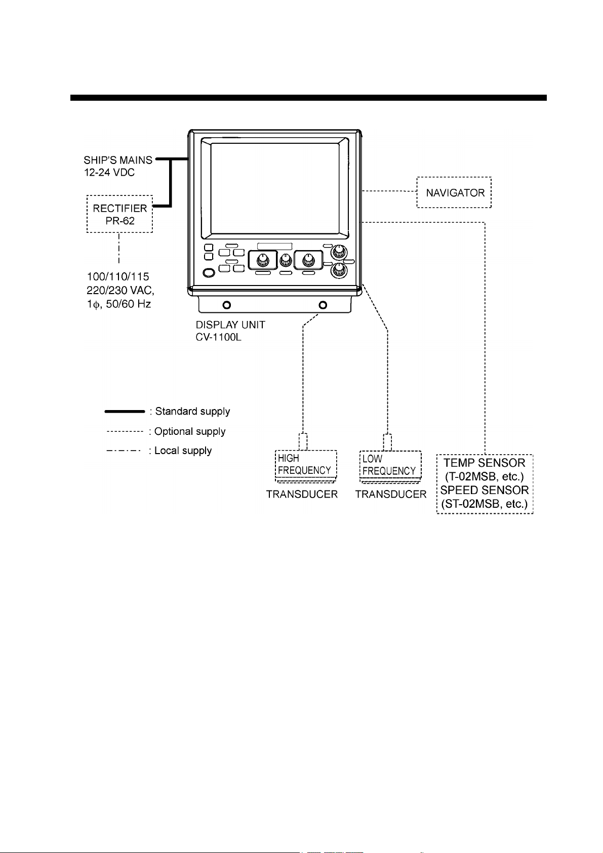
SYSTEM CONFIGURATION
System configuration
v
Page 8

This page is intentionally left blank.
vi
Page 9
1. OPERATIONAL OVERVIEW
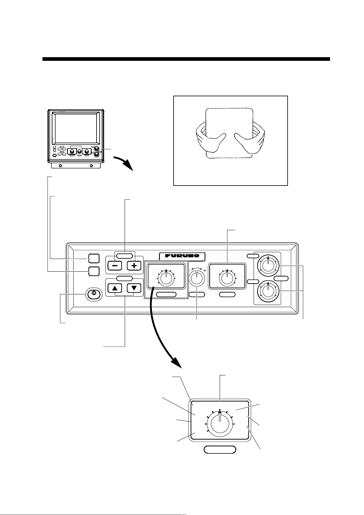
1.1 Controls
Correct key operation:One beep
Invalid key operation: Two beeps
Control Panel
Adjusts display brilliance.
(P. 1-3)
Inscribes vertical
line on the display.
Current position is output
to navigation plotter with
connection of navigator.
(P. 1-14)
MARKER
TLL
BRILL
PWR
SHIFT/PROG
VRM
HOW TO REMOVE THE HARD COVER
While pressing the center of the cover
with your thumbs as illustrated, pull the
cover towards you.
· Shifts the display area. (P. 1-12)
· Changes menu setting. (P. 2-1)
· Executes programmed function. (P. 1-22)
Selects a display.
(P. 1-4)
COLOR LCD SOUNDER FCV– 1100L
ZOOM
LF
DUAL
MODE
HF
ZOOM
USER1
USER2
ADVANCE/A-SCOPE
SIG LEVEL
TVG
CLUTTER
EXIT
FUNCTION
NL
PROG
MENU
RANGE
HF
4
6
28
0
10
LF
4
6
28
0
10
GAIN
Turns power
on/off. (P. 1-2)
· Shifts VRM/White
Marker. (P. 1-13, P. 2-4)
· Selects menu item.
(P. 2-1)
Opens the SIGNAL
LEVEL menu. (P. 1-17)
Opens the TVG
menu. (P. 1-16)
Opens the CLUTTER
menu. (P. 1-15)
Closes menu.
Controls
Selects a
display range. (P. 1-11)
Opens the PIC ADVANCE/A-SCOPE
menu. (P. 1-18, P. 1-20)
ADVANCE/A-SCOPE
SIG LEVEL
TVG
CLUTTER
EXIT
NL
FUNCTION
Adjusts gain of high and
low frequencies individually.
(P. 1-13)
Opens the NOISE
PROG
MENU
LIMITER menu.
(P. 1-21)
Opens the
USER menu.
(P. 2-12)
Opens the main
menu. (P. 2-1)
1-1
Page 10
1. OPERATIONAL OVERVIEW
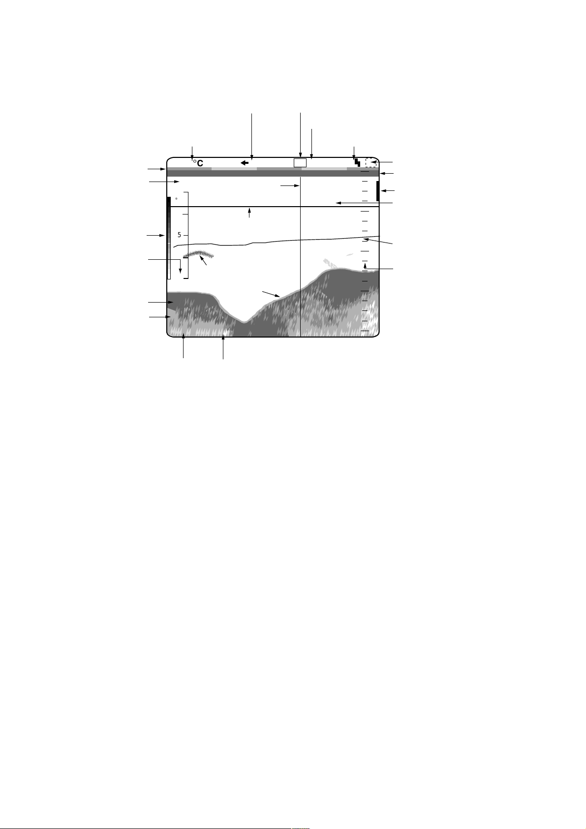
1.2 Indications
Minute marker
Elapsed time
(From pressing
MARKER/TLL
key)
Color bar
Temperature scale*
Ship's speed*
Depth
Picture advance speed
Water temperature*
5.30°C
0H01M
10
°
C
5
Fish school
0
17.8kt
49.6
1'21" <P/R>
Scroll time
m
Transducer power reduction
1/1
Marker
line
VRM
Bottom
echo
Frequency
Noise limiter
LF
N1
19.7
Shift
0
20
40
60
80
0
Alarm type
Zero line
Alarm marker
Depth to VRM
Water temperature graph*
Depth scale
*: Appropriate sensor
required.
Indications
1.3 Turning the Power On/Off
1. Press the [PWR] key. A beep sounds, and then the power turns on.
2. Press the [PWR] key again to turn the power off.
Note 1: Wait five seconds before turning on the power again.
Note 2: The example screens shown in this manual may not match the screens
you see on your display. The screen you see depends on your system
configuration and equipment settings.
1-2
Page 11

1.4 Adjusting LCD Brilliance
The brilliance of the LCD may be adjusted as below. Ten levels are available.
1. Press the [BRILL] key.
BRILL
1. OPERATIONAL OVERVIEW
B R I L L (9)
2. Press the [+] or [-] key to adjust the LCD brilliance; [+] key to raise the
brilliance, [-] key to lower it.
Note 1: Brilliance is automatically set to maximum at the next power on, when
the unit is turned off with the brilliance setting of 4 or lower.
Note 2: Brilliance must be adjusted within five seconds after pressing the
[BRILL] key or the brill window will be erased.
[] []
Brill window
1-3
Page 12
1. OPERATIONAL OVERVIEW
1.5 Display Mode
Seven display modes are available with the [MODE] switch.
MODE
LF-ZOOM
LF
DUAL
HF
HF-ZOOM
USER-1
USER-2
Display mode window
1.5.1 Single-picture (low frequency or high frequency) display
Low frequency (LF)
The lower the frequency of the ultrasonic pulse the wider the detection area.
Thus, the low frequency is suitable for general search and judging bottom
condition.
High frequency (HF)
Currently selected mode
shown in reverse video
The higher the frequency of the ultr asonic pulse the better the resolution.
Therefore, the high frequency pulse is useful for detailed observation of f ish
echoes.
LF
0.0
20
40
60
80
Low
frequency
Frequency and Detection Area
High
frequency
Fish school
49.6
1/1
Bottom echo
m
Single-frequency Picture
Frequency and detection area, sample single picture (low frequency)
0
0
1-4
Page 13
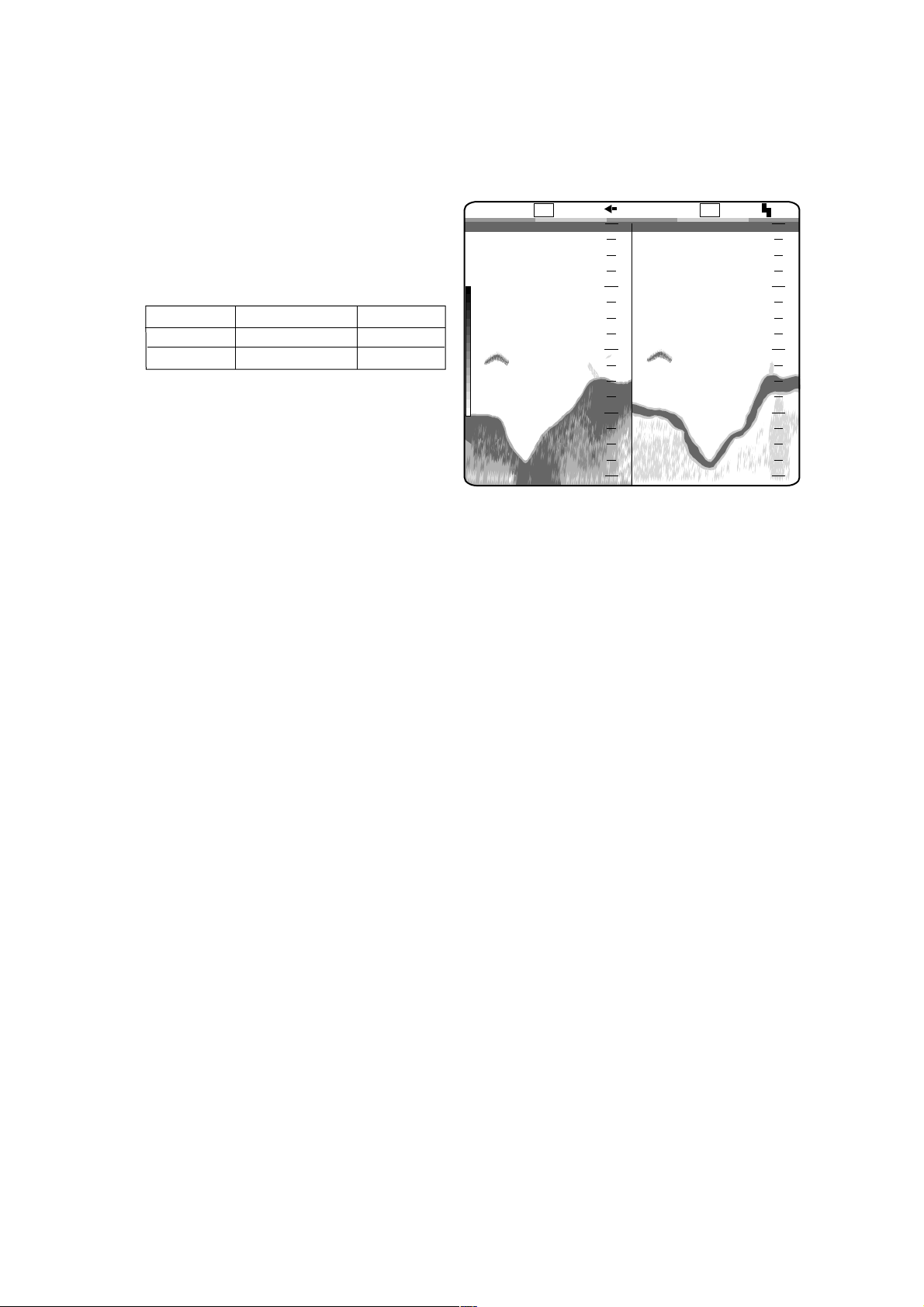
1.5.2 Dual frequency display
The dual frequency display provides the low frequency picture on the left half of
the screen; the high frequency picture on the right half.
1. OPERATIONAL OVERVIEW
Frequency
Low
High
Beamwidth
Wide
Narrow
frequency
Echo Trail
Long
Short
49.6
Dual frequency display
Low
m
20
40
60
80
1/1
0
HFLF
0.0
High
frequency
20
40
60
80
0
0
1-5
Page 14
1. OPERATIONAL OVERVIEW
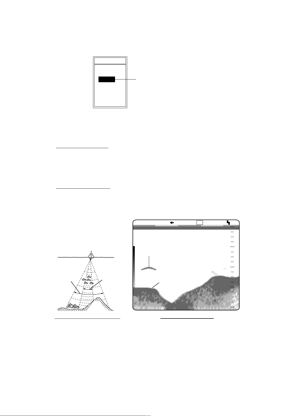
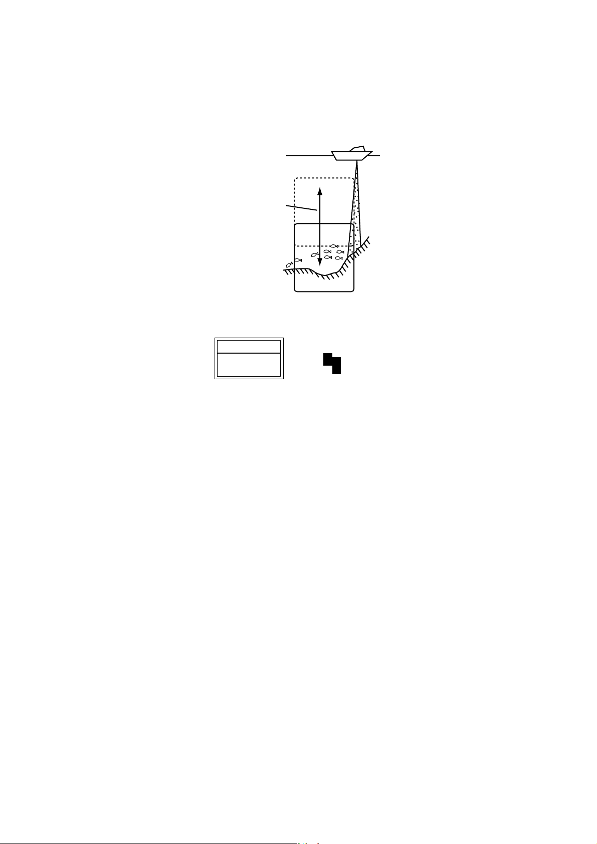
1.5.3 Zoom displays
The “single-frequency picture” (high or low frequency) appears on the right half
of the screen and the zoom picture on t he left half. The zoom picture may be
pre-chosen among bottom lock, bottom zoom, marker zoom and discrim ination,
from the SYSTEM SETTING menu. For further det ails, see ZOOM MODE on
page 3-3.
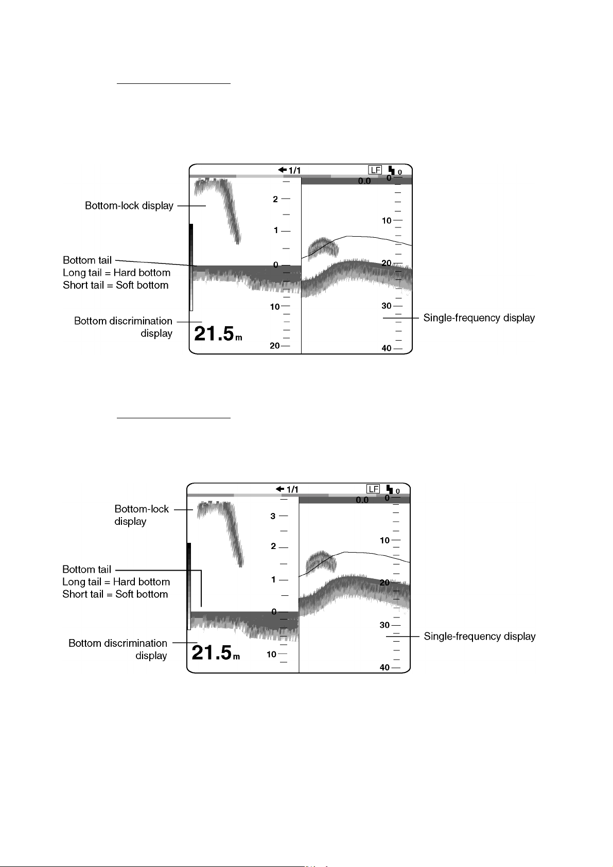
Bottom-lock display
The bottom-lock display shows the area between the zoom marker and the
bottom as a straight line to dist inguish it from fish near the bottom, and thus it is
useful for discriminating fish near the bottom .
The bottom-lock zoom range may be chosen on the RANGE SETTING menu.
For further details see B/L RANGE on page 3-5.
Bottom-lock display
Zoomed fish school
Bottom shown
as a straight line
21.7
1/1
5
4
3
2
1
m
0
Bottom-lock display
Fish
school
0.0
LF
10
20
30
40
0
0
Zoom marker
This area zoomed
and displayed on
left 1/2 of screen
Single-frequency display
1-6
Page 15
1. OPERATIONAL OVERVIEW
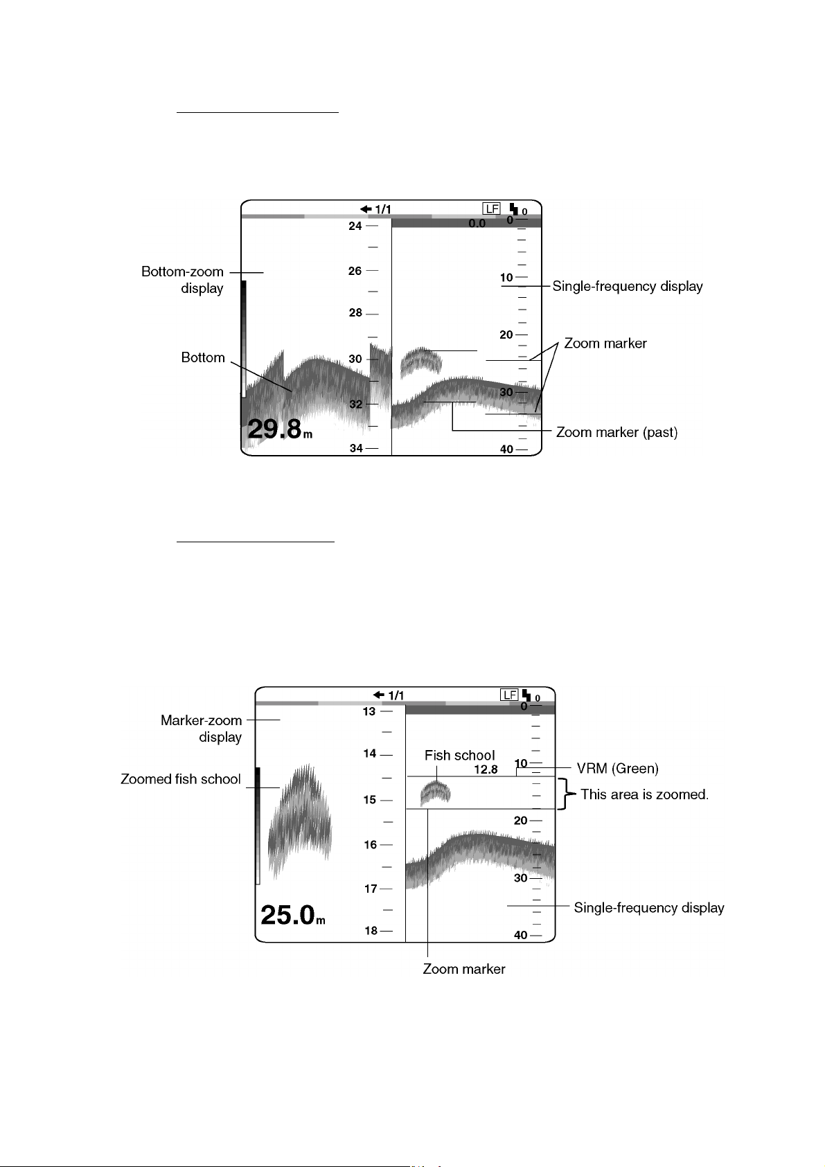
Bottom-zoom display
The bottom-zoom display shows the zoomed bottom (automatically tracked) on
the left half of the screen. When the bottom depth increases, the display shifts to
keep the bottom echo at the lower part of the screen.
Bottom-zoom display
Marker-zoom display
The marker-zoom display expands the area chosen with the VRM on the normal
picture to full vertical size of the screen on the left half of the screen. T his mode
is useful for observing a specific fish school.
The marker-zoom range may be chosen on the RANGE SETTING m enu. For
further details see M/Z RANGE on page 3-5.
Marker-zoom display
1-7
Page 16
1. OPERATIONAL OVERVIEW
DISCRIM 1/2 display
The discrim(ination) 1/2 screen shows the single picture on the right half of the
screen and the bottom-lock display and discriminator display occupy the left half
of the screen. The discrim inator display shows the bottom as a straight line,
which is useful for determining bottom hardness.
Discrimination 1/2 display
DISCRIM 1/3 display
This display is similar to the DISCRIM 1/2 display except the bottom
discriminator display occupies the bottom one-third of the left half of the screen
as below.
1-8
Discrimination 1/3 display
Page 17
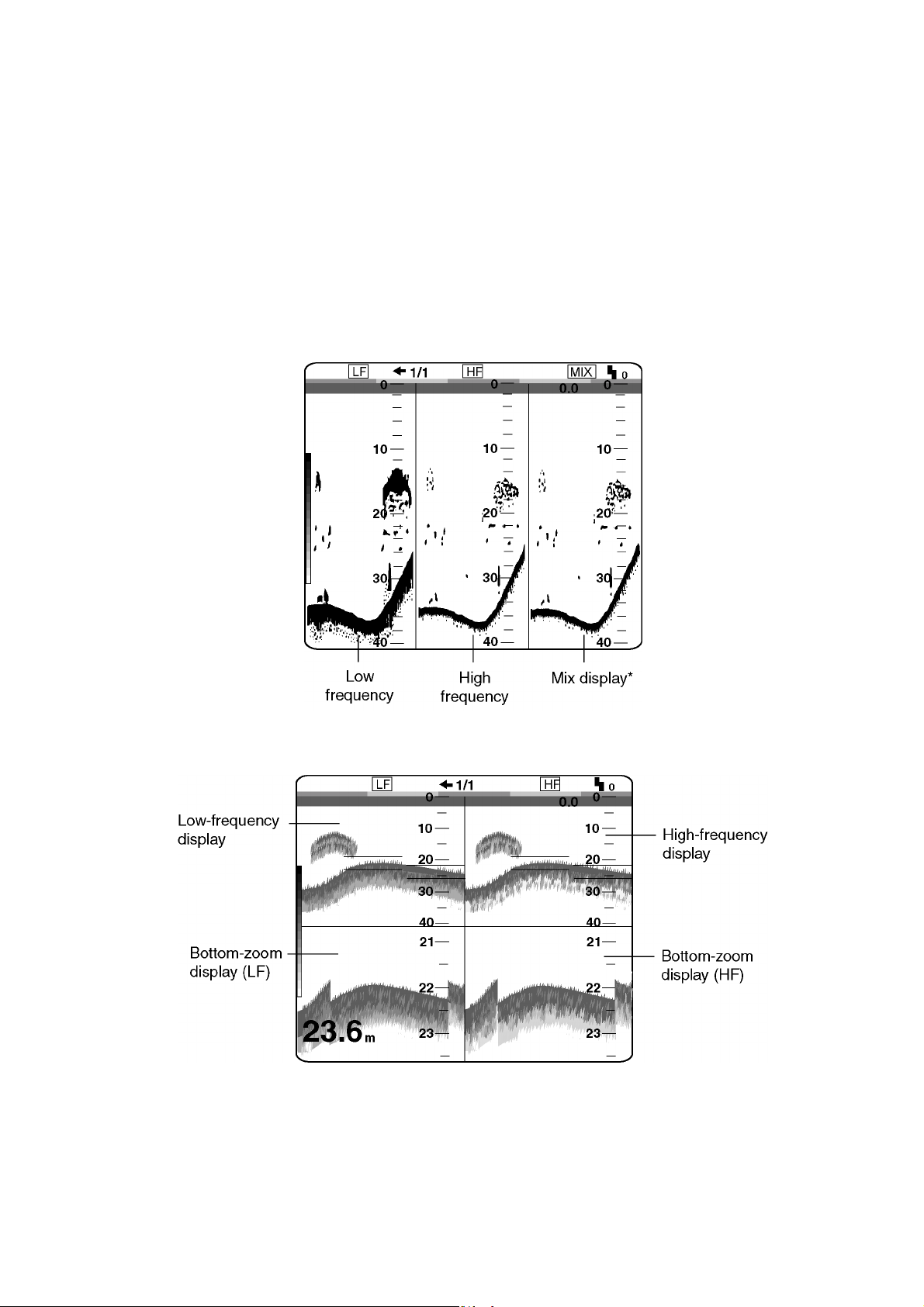
1.5.4 USER-1, -2 displays
The display programmed at USER-1/ 2 on the USER menu appears. The default
settings are as follows:
USER 1: Screen is split vertically in thirds (LF + HF + MIX)
USER 2: Screen is split vertically in fourths (LF + HF + LF bottom zoom +HF
bottom zoom)
This setting may be changed through the USER menu. For further details, see
“USER-1/2” on page 2-12.
1. OPERATIONAL OVERVIEW
User 1 display (default display)
User 2 display (default display)
1-9
Page 18
1. OPERATIONAL OVERVIEW
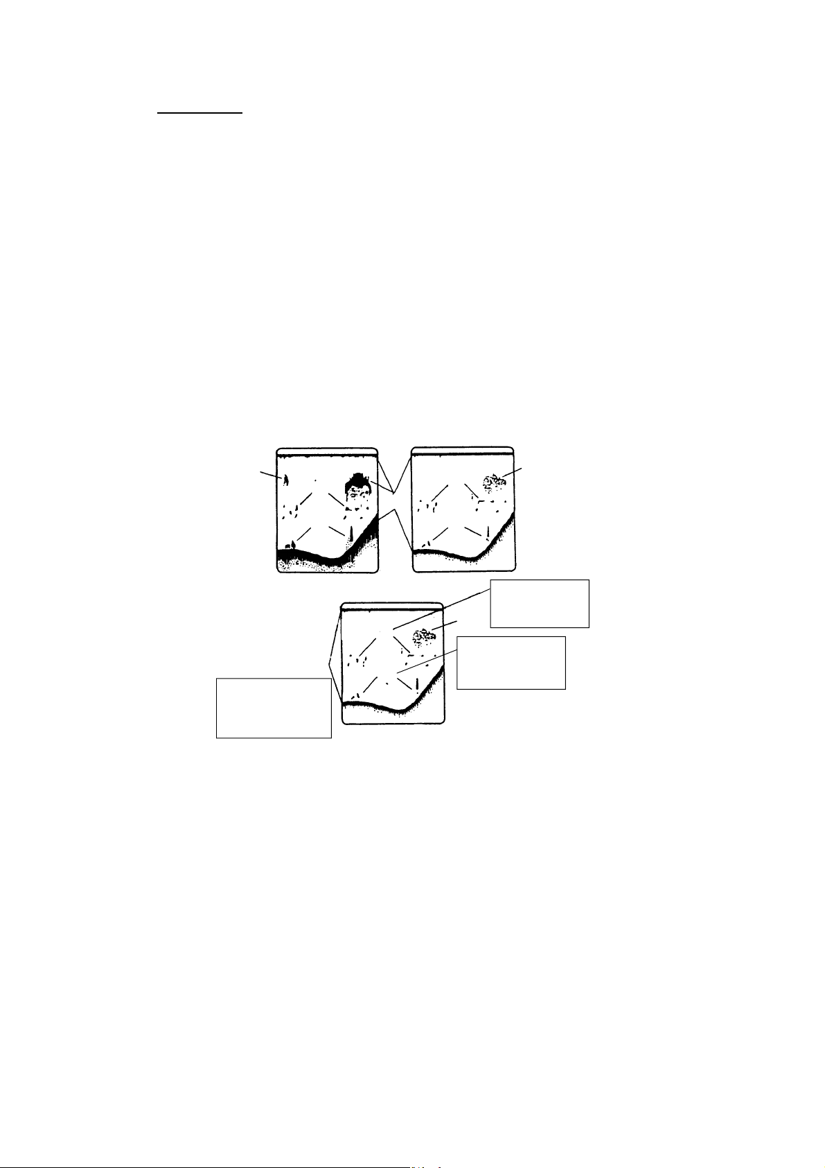
Mix display
The mix display compares echo intensity between low and high frequencies, and
displays echoes from tiny fish in discriminative colors. This is done by utilizing
the fact that tiny fish return a stronger echo against a high frequency rather than
a low frequency. This is done as below.
1. If a high frequency echo is stronger than the corresponding echo on the low
frequency, the high frequency echo is displayed.
2. If the low frequency echo is stronger than or equal to the high frequency echo,
it is less likely to be a tiny fish and therefore is displayed in blue.
3. If the echoes on both frequencies have the intensity corresponding to
reddish-brown or red, they are displayed in reddish-brown or red: this is
necessary to display the zero line and bottom in reddish-brown or red.
4. In other words, the echoes displayed in orange thru light-blue may be
considered to be tiny fish such as whitebait.
Low frequency
Blue
GRN
RED
Reddish-brown
Displayed in reddishbrown since high
freq. echoes are
red or reddish brown.
How the mix display works
High frequency
R-BRN
+
Discriminator
YEL
BLU
YEL
ORG
These echoes
are likely to be
Blue
small fish.
Displayed in blue
since high freq.
echo is weaker.
Green
1-10
Page 19
E
1.6 Choosing Basic Range
The basic range may be chosen with the [RANGE] switch from the eight ranges
listed below. These eight ranges may be programmed as desired on the RANGE
SETTING menu. For details, see page 3-5.
RANG
30ft
60ft
120ft
250ft
500ft
1000ft
1600ft
3000ft
Range setting window (example: feet)
1. OPERATIONAL OVERVIEW
Basic ranges (default settings)
Range Switch Position
Range Unit
1 2 3 4 5 6 7 8
Feet (default) 30 60 120 250 500 1000 1600 3000
Meter 10 20 40 80 150 300 500 1000
Fathom 5 10 20 40 80 160 250 500
Hiro (Japanese) 6 12 25 50 100 200 300 600
Passi/Braza 6 12 25 50 100 200 300 600
Note 1: This setting must be done within five seconds after rotating the [RANGE]
switch once, otherwise the range window will be erased.
Note 2: Range for high and low frequencies can be set separately.
Note 3: The unit of depth measurement may be chosen from the SYSTEM
SETTING menu. For details, see DEPTH UNIT on page 3-2.
1-11
Page 20
1. OPERATIONAL OVERVIEW
10
1.7 Shifting the Basic Range
The [-] and [+] keys determine the start depth (shown at the top of the screen) of
the picture. In the default setting any shift is reflected on other ranges. This
feature is not available when AUTO SHIFT is active.
Shift the start
depth to watch
shallow or deep.
picture
Principle of shift
SHIFT
10ft
Shift window (screen center), shift indication (top right corner)
Note 1: This operation must be done within five seconds after pressing the [-] or
[+] key, otherwise the shift window will be erased.
Note 2: Automatic shift, which provides virtually hands-free automatic operation,
is also available. For further details, see AUTO SHIFT on page 3-3.
Note 3: You can shift the display independently for each range by turning on
FREE SHIFT, on the SYSTEM SETTING menu. For details, see FREE
SHIFT on page 3-2.
1-12
Page 21
1.8 Adjusting Gain
The [GAIN] control adjusts the sensitivity of the receiver. Adjust it so excessive
noise just disappears from the screen.
1. OPERATIONAL OVERVIEW
Gain too high Gain proper
Examples of proper and improper gain levels
1.9 Measuring Depth
Use the [▲] or [▼] key to place the VRM on the object to measure depth. Depth
is digitally displayed above the VRM.
Note: This operation is available by setting MARKER SELECT on the DISP
menu to “VRM.”
1/1
VRM (green)
Gain too low
LF
Depth to VRM
39.8
20
40
0
0
60
49.6
m
80
How to use the VRM
1-13
Page 22
1. OPERATIONAL OVERVIEW
1.10 Marker Line
The [MARKER/TLL] key inscribes a vertical marker line on the screen when
pressed. It may be used to denote a fish school or other important echo.
At the same m oment the key is pressed, latitude and longitude position are
output to a navigation plotter and marked on its screen if this unit is interfaced
with position-fixing equipment.
Elapsed time from the moment the [MARKER/TLL] key is pressed may be
displayed at the upper-left corner of the screen. For further details, see SCROLL
TIME on page 2-3.
Elapsed time
from when the
[MARKER/TLL]
key is pressed.
LF
0.0
0H01M
49.6
1/1
m
Marker line and elapsed time indication
20
40
60
80
0
0
Marker line
Shown in second color
from top of color bar in
16-color display; the top
color of color bar in 8-color
display.
1-14
Page 23
1.11 Suppressing Clutter
When blue dots appear over the entire screen (mainly caused by sediments in
the water), use the clutter function to suppress them.
1. Rotate the [FUNCTION] switch to choose CLUTTER.
HF•CLUTTER : 2 (0 5)
HF•CURVE : STD
LF•CLUTTER : 2 (0 5)
LF•CURVE : STD
Color changes
depending on
clutter level
and curve.
1. OPERATIONAL OVERVIEW
CLUTTER
LOW HIGH
Change echo color
assignment.
[-/+]: Change setting
[EXIT]: Exit
Clutter menu
• For dual frequency display: Go to step 2.
• For other modes: Go to step 3 after pressing the [▼] key.
2. Press the [▲] or [▼] key to choose HF CURVE or LF CURVE as appropriate.
3. Press the [-] or [+] key to open the clutter curve selection window (default:
STD).
LINEAR CUSTOM
STD
Clutter curve selection window
STD: The higher the clutter level the smaller weak echoes are displayed.
LINEAR: The higher the clutter level the smaller all echoes are displayed.
CUSTOM: Applies the user clutter settings from the user clutter menu. See
page 2-17.
4. Press the [-] or [+] key to choose clutter curve desired.
5. Press the [▲] or [▼] key to close the window.
6. Press the [▲] key to choose HF CLUTTER or LF CLUTTER as appropriate.
7. Press the [-] or [+] key to set clutter rejection level: 0, OFF; 1, weakest,
5, strongest.
8. Rotate the [FUNCTION] switch fully counterclockwise to choose EXIT.
Note: Clutter cannot be adjusted manually when using the auto mode. Turn off
the auto mode on the E/S menu to manually adjust clutter. For details see
page 2-11.
1-15
Page 24
1. OPERATIONAL OVERVIEW
1.12 Adjusting TVG
The TVG compensates for propagation loss of sound, so that the echoes from
the same size fish schools are displayed in the same color. Avoid excessive
TVG; weak echoes may not be displayed. The TVG is also useful for reducing
surface noise.
0m
100
How TVG works
1. Rotate the [FUNCTION] switch to choose TVG.
TVG
HF·TVG LEV : 5 (0~10)
HF·TVG DIST: 600ft
LF·TVG LEV : 5 (0~10)
LF·TVG DIST : 600ft
0ft
This scale is
synchronized with the
distance value setting.
0m
100
600
low
Adjust TVG effective
distance.
[-/+]: Change setting
[EXIT]: Exit
Gain high
ft
TVG menu
•
For dual display: Go to step 2.
•
For other display modes: Go to step 3 after pressing the [▼] key.
2. Press the [▲] or [▼] key to choose HF TVG DIST or LF TVG DIST as
appropriate.
3. Press the [-] or [+] key to set the TVG distance. The larger the setting, the
longer the range at which TVG works. The scale on the menu synchronizes
with the rate setting.
4. Press the [▲] or [▼] key to close the window.
1-16
Page 25
5. When surface noise appears in the range shallower than the setting range,
press the [▲] key to choose HF TVG LEVEL or LF TVG LEVEL as
appropriate.
6. Press the [-] or [+] key to set the TVG level in the setting window. The higher
the TVG level, the less the gain near distance.
5
TVG level setting window
7. Rotate the [FUNCTION] switch fully counterclockwise to choose EXIT.
1.13 Eliminatin g Weak Echoes
Sediments in the water or reflections from plankton may be painted on the
display in green or light-blue. These weak echoes may be erased with the signal
level function.
1. Rotate the [FUNCTION] switch to choose SIG LEVEL.
1. OPERATIONAL OVERVIEW
SIGNAL LEVEL
SIGNAL LEV : OFF
Echo colors
disappear from
weakest to
OFF
Eliminate low
intensity echoes.
[-/+]: Change setting
[EXIT]: Exit
current
strongest.
Signal level menu
2. Press the [-] or [+] key to choose the setting desired. Every pressing of the [+]
key deletes echoes from weakest to strongest in ascending order. (For eight
colors, the setting window shows OFF, 1 to 4.)
987654321OFF
Signal level setting window (for 16 colors)
3. Rotate the [FUNCTION] switch fully counterclockwise to choose EXIT.
1-17
Page 26
1. OPERATIONAL OVERVIEW
1.14 Picture Advance Speed
The picture advance speed determines ho w quickly the vertical scan li nes run
across the screen.
1. Rotate the [FUNCTION] switch to choose ADVANCE/A-SCOPE.
PIC ADVNC/A-SCOPE
PIC ADVNC : 1/1
A-SCOPE : OFF
For picture advance
and A-SCOPE setting.
[-/+]: Change setting
[EXIT]: Exit
PIC ADVNC/A-SCOPE menu
2. Press the [-] or [+] key to choose the speed desired.
1/16STOP 1/8 1/4 1/2 1/1 2/1 3/1 4/1
Picture advance speed setting window
The fractions in the window mean the num ber of vertical scan lines produced
per transmission. For example, “1/2” means a vertical scan line is pro duced
every two transmissions. These fractions also appear at t he top of the
screen for your reference.
When choosing an advance speed, keep in m ind that a fast advance speed
will expand the size of a fish school horizontally and a slow speed will
contract it.
1/1 S
"S" means picture advance speed is
synchronized with ship's speed.
1-18
Speed indication
3. Rotate the [FUNCTION] switch fully countercl ockwise to choose EXIT.
Page 27

1. OPERATIONAL OVERVIEW
Ship’s speed dependent mode
With speed data provided by a speed log, current indicator or navigation
equipment, the display advance speed may be set according to ship’s speed, the
ship’s speed dependent mode. As shown in the figure below the horizontal scale
of the display is not influenced by the change of ship’s speed, thus the
speed-dependent picture advance permits judgment of fish school size and
abundance at any speed. The picture advance speed indication is suffixed with
an “S” when the ship’s speed dependent mode is active. For example, “1/1S.”
This function is available with ship’s speed of 2-20 kt. You can use the ship’s
speed dependent mode by setting PRR LEVEL to “S” on the TX/RX menu. For
further details, see PRR LEVEL on page 2-8.
Fish school is shrunk at high
ship's speed; expanded at
low ship's speed.
Same size
fish schools
Speed
FULL SPEED HALF SPEED
Actual Movement
How the ship’s speed dependent mode works
Normal Mode
Fish schools are shown
same size regardless of
ship's speed.
Ship's Speed Dependent Mode
1-19
Page 28

1. OPERATIONAL OVERVIEW
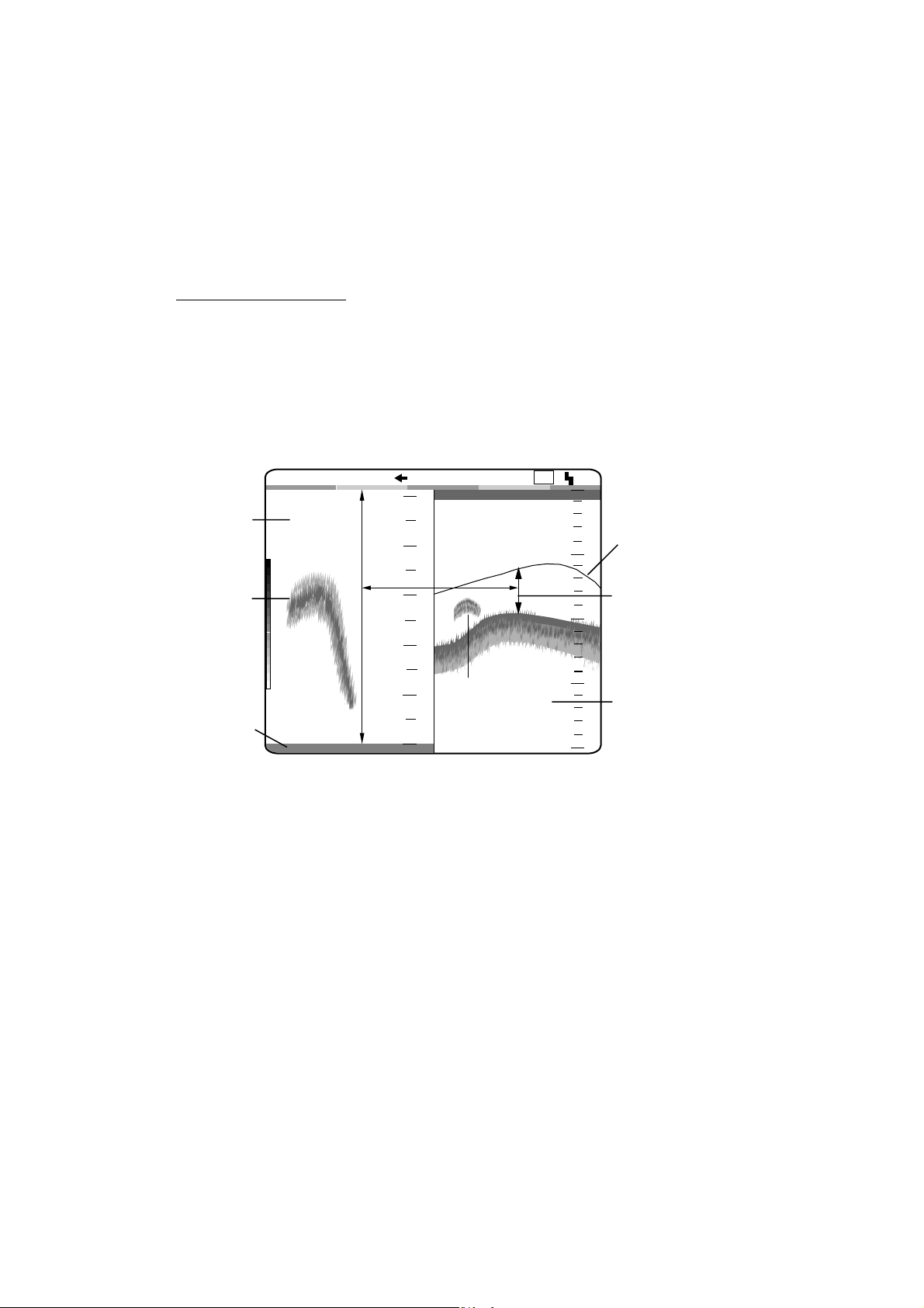
1.15 A-Scope Display
The A-scope picture displays echoes at each transmission with amplitudes and
colors proportional to their intensities on the right one-fourth of the screen. This
feature is useful for close observation of small fish and fish near the bottom.
Note: For the dual-frequency display and vertical split screen, the A-scope
display is only available with the high frequency display. In case of the
horizontal split screen, high and low frequency A-scope displays appear.
1. Rotate the [FUNCTION] switch to choose ADVANCE/A-SCOPE to show the
PIC ADVANC/A-SCOPE menu.
2. Press the [▼] key to choose A-SCOPE.
3. Press the [+] key twice to choose ON from the setting window.
OFF ON
A-scope selection window
4. Rotate the [FUNCTION] switch to choose EXIT.
5. To turn off the A-scope display, press the [-] key twice to choose OFF at step
3 in this procedure.
LF
20
40
60
80
0
0.0
0
A-scope Display
Weak echo (fish)
Strong echo (bottom)
Single
frequency
59.6
1/1
m
1-20
A-scope display
Page 29

1.16 Suppressing Interference
Interference from other acoustic equipment operating nearby or other electronic
equipment on your boat may show itself on the display as shown in the figure
below. You may suppress these types of interference with the noise limiter.
1. OPERATIONAL OVERVIEW
Interference from
other sounder
Electrical interference
Interference
1. Rotate the [FUNCTION] switch to choose NL.
NOISE LIMITER
HF·FREQ ADJ : +0.0%
The inverted solid
-10
HF·NOISE LIM: OFF
LF·FREQ ADJ : +0.0%
-10
LF·NOISE LIM : OFF
1. Shift frequencies to
reject interference.
2. Use LF/HF·NOISE LIM
in case interference
hasn't been rejected.
[-/+]: Change setting
[EXIT]: Exit
0
0
+10
+10
triangle shifts with
operation of [-] or
[+] key.
NL menu
•
For the dual display: Go to step 2.
•
For other modes : Go to step 3.
2. Press the [▲] or [▼] key to choose HF•FREQ ADJ or LF•FREQ ADJ,
whichever is appropriate.
1-21
Page 30

1. OPERATIONAL OVERVIEW
3. Press the [-] or [+] key to set appropriate value in the setting window so that
interference disappears. The setting range for most transducers is -10.0% to
+10.0%. However the transducer listed below have different setting ranges.
50 kHz: -10% - +6%
67 kHz /68 kHz: -4% - +10%
107 kHz: -10% - +4%
200 kHz: -9% - +10%
The transducer having the frequency near 54-64 kHz, 112-122 kHz or
171-181 kHz has adjustment limitations. For example, the adjustment range
for 66 kHz is –2% - +10%.
If interference is still present, go to step 4, otherwise go to step 7.
4. Press the [▲] or [▼] key to close the setting window.
5. Press the [▼] key to choose HF•NOISE LIM or LF•NOISE LIM, whichever is
appropriate.
6. Press the [-] or [+] key to choose the noise rejection setting among N1, N2
and N3. N3 provides the highest level of interference suppression.
OFF N1
Signal level setting window
7. Rotate the [FUNCTION] switch to choose EXIT.
Note: Turn the noise limiter off when no interference exists, otherwise weak
echoes may be missed.
1.17 SHIFT/PROG Key
The [SHIFT/PROG] key is a “soft key” which the operator may program to
provide instant access to a function. Simply press the [+] or [-] key to access the
function programmed. An appropriate setting window appears. (The illustration
below shows the SHIFT window.) Then, press the [+] or [-] key again to select
desired setting.
N2
SHIFT
N3
0 ft
1-22
SHIFT window
You can select the soft key function with SHIFT/PROG on the USER menu, and
the default setting is “SHIFT.” For further details, see SHIFT/PROG on page
2-15.
Page 31

2. MENU OPERATION
2.1 Basic Menu Operation
The main menu, consisting of the DISP (display), ALM (alarm), TX/RX, E/S and
SYSTEM menus, contains various items which once preset do not require
frequent adjustment. The operator may set t hese items as appropriate to suit
operating needs.
1. Rotate the [FUNCTION] switch fully clockwise to choose MENU. The
last-used menu among DI SP, ALM, T X /RX, ES and SYSTEM appears. The
illustration below shows the DISP menu.
Menu titles
Description for
selection.
DISP ALM TX/RX E/S SYSTEM
NO. OF COLORS : 16
HUE : STD
BACKGROUND : BLUE
WHITE LINE : OFF (OFF, 1~10)
DEPTH INFO : STD
MARKER SELECT : VRM
ZOOM MARKER : ON
DISPLAY DATA : TIMER
SCROLL TIME : OFF
ECHO STRETCH : OFF
SMOOTHING-1 : 3 (OFF,1~4)
SMOOTHING-2 : OFF
Menu for display setting.
[-/+]: Change set, [EXIT]: Exit
DISP menu
2. Press the [▲] key to choose menu title area.
3. Press the [+] or [-] key to choose menu desired among DISP, ALM, TX/RX,
ES and SYSTEM. The menu chosen is highlighted.
4. Press the [▲] or [▼] key to choose item. For exam ple, choose NO. OF
COLORS. (Menu help for the item chosen appears at the bottom of the
screen.)
5. Press the [-] or [+] key to display the setting window. The illustration below
shows the selection window for NO. OF COLORS.
8 16
Selection window for NO. OF COLORS
2-1
Page 32

2. MENU OPERATION
6. Press the [-] or [+] key to change the setting. For items having several
options, a scroll bar (blue) appears. This bar shows the current cursor
position in relation to the entire option range. This bar shifts with operation of
the [-] or [+] key.
Selection window (for item having several options, for example, HUE)
7. Rotate the [FUNCTION] switch fully counterclockwise to choose EXIT.
Blue bar
CUSTOM STD HUE1 HUE2 HUE3 HUE4
The blue bar shows the current cursor position in
relation to the option range.
This bar shifts with operation of [-] or [+] key.
2-2
Page 33

2.2 DISP Menu
The DISP menu allows the user to setup up the display as desired.
DISP ALM TX/RX E/S SYSTEM
NO. OF COLORS : 16
HUE : STD
BACKGROUND : BLUE
WHITE LINE : OFF (OFF, 1~10)
DEPTH INFO : STD
MARKER SELECT : VRM
ZOOM MARKER : ON
DISPLAY DATA : TIMER
SCROLL TIME : OFF
ECHO STRETCH : OFF
SMOOTHING-1 : 3 (OFF,1~4)
SMOOTHING-2 : OFF
2. MENU OPERATION
Menu for display setting.
[-/+]: Change set, [EXIT]: Exit
For picure advance speed: 2/1, 3/1, 4/1
For picture advance speed: 1/16, 1/8, 1/4, 1/2, 1/1
DISP menu
NO. OF COLORS
Chooses eight color or sixteen-color presentation.
HUE
Chooses desired picture color. USER displays the colors programmed by the
user. (See page 2-16.) STD is the standard colors used on most FURUNO video
sounders. HUE 1-7 provide other picture color arrangements.
BACKGROUND
Chooses background color to black, dark blue, blue, light -blue or white. Note that
the background color is fixed when the user color (in HUE above) is chosen.
WHITE LINE
Changes the strongest signal color to white. The higher the setting, the wider the
white line. Generally, fish schools on or close to the bottom are displayed on the
screen as if they are a small rising from the bottom. This feature can help
discriminate bottom fish schools f rom the bot t om .
DEPTH INFO
Changes the size and location of t he depth indication.
2-3
Page 34

2. MENU OPERATION
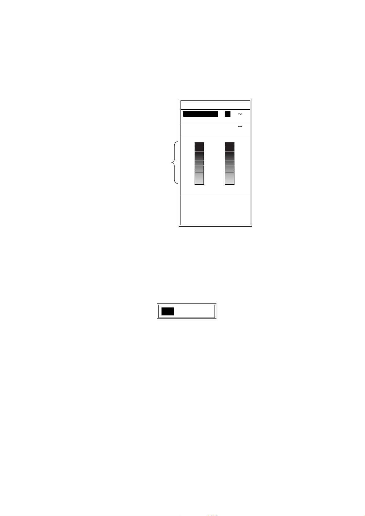
MARKER SELECT
Chooses the marker function, VRM or WHITE MARKER.
VRM: Measures depth to an echo.
WHITE MARKER: Display a specific echo color in white. This feature is useful
for discriminating bottom fish from the bottom.
(White marker operation)
1. After choosing EXIT with the [FUNCTION] switch to close the menu, press
the [▲] or [▼] key to show the white marker setting window.
WHITE MARKER
Color bar
The color selected
by this red arrow
changes to white.
OFF
/ : Select color
to enhance.
White marker setting window
2. Press the [▲] or [▼] key to choose the echo color which you want to
emphasize. The setting window disappears if there is no key operation within
five seconds. The color chosen to display in white is shown in white on the
color bar.
Note: Before changing from WHITE MARKER to VRM, you must choose OFF in
the white marker setting window.
ZOOM MARKER
Turns the zoom marker on/off.
DISPLAY DATA
2-4
Chooses the data to display at the left top corner of the screen among OFF, L/L*,
TD*, TIMER (Elapsed time from the moment the [MARKER/TLL] key is pressed),
GAIN (See note below), R/B* (range and bearing to the waypoint) and
COURSE*.
*: Requires navigation device.
Note: The gain setting shown on the display may not agree exactly with GAIN
control position. The gain setting shown on the display is the correct value.
Page 35

2. MENU OPERATION
SCROLL TIME
Turns the display scroll time on or off. Scroll time, shown at the bottom left
corner of the display, shows the amount of time a scan line stays on the screen
as it passes from one side of the screen to the other. Time varies with the range
and picture advancement speed.
ECHO STRETCH
Displays the strong echoes long though the pul selengt h setting is short. It is
useful for distinguishing individual fish (for example, squid) from plankton.
SMOOTHING-1
This function smoothes echo presentation, an d can only be changed when the
picture advance speed is set to 1/16, 1/8, 1/4, 1/2 or 1/1. (See page 1-18.) The
higher the number, the greater the smoothing. Adjust the setting when echoes
appear “spotty.”
SMOOTHING-2
This function smoothes the “mosaic-like” echo presentation, and can only be
changed when the picture advance speed is set to 2/1, 3/1 or 4/1. (See page
1-18.)
2-5
Page 36

2. MENU OPERATION
2.3 ALM Menu
The ALM menu sets the bottom, fish and water tem perature alarms. To silence
the alarm beep, press the [-] , [+], [▲] or [▼] key.
BOTTOM ALARM
When your ship comes in the area of the chosen depth, beeps sound and the
indication “BTM” flashes at the top right corner to draw your attention.
FISH ALARM
FISH ALARM: Fish echoes of yellow or stronger colors (default setting) trigger
the alarm.
BTM-FISH ALARM: When fish echoes come in the area which you set above the
bottom, beeps sound and the indication “F ISH” flashes at the top right corner of
the screen. (Available modes: bottom lock, discrim 1/2, discrim 1/ 3)
TEMP ALARM
Chooses temperature range which triggers temperat ure alarm. Audio and visual
(“TEMP”) alarms are released when water temperature is within the range or out
of the range of the preset value. This function requires a water temperature
sensor.
2.3.1 Setting the alarm
1. Rotate the [FUNCTION] switch fully clockwise to choose MENU.
2. Press the [▲] key to choose the menu title area.
3. Press the [-] or [+] key to choose ALM to display the ALM m enu.
DISP ALM TX/RX E/S SYSTEM
BOTTOM ALARM : OFF
ALARM DEPTH : 0 ft
ALARM ZONE : 10 ft
FISH ALARM : OFF
ALARM DEPTH : 0 ft
ALARM ZONE : 10 ft
ALARM LEVEL : MID
TEMP ALARM : OFF
TEMP LIMIT : 65.00°F(20~95)
ALARM ZONE : 1.00°F
*
*
*
2-6
Menu for alarm setting.
[-/+]: Change set, [EXIT]: Exit
*: The setting is not available when ALARM
is OFF.
ALM (Alarm) menu
Page 37

2. MENU OPERATION
4. Press the [▲] or [▼] key to choose the alarm which you want to set.
5. Press the [-] or [+] key to show the alarm setting window.
OFF ON
Bottom alarm
6. Press the [-] or [+] key to choose the alarm type desired.
7. Press the [▼] key twice to choose ALARM DEPTH (TEMP LIMIT for temp
8. Press the [-] or [+] key to show the alarm setting window.
9. For BOTTOM ALARM and FISH ALARM, press the [-] or [+] key to set the
OFF FISH BTM-FISH
Fish alarm
OFF WITHIN RANGE OUT OF RANGE
Temp alarm
Alarm setting window
alarm).
0 m
Starting depth setting window (example: bottom alarm)
starting point of alarm zone. Alarm marker appears (Depth alarm: green, Fish
alarm: white). The starting depth is measured from the transducer surface for
BOTTOM ALARM and FISH ALARM, from the bottom for BTM-FISH (bottom
fish) alarm.
Selected alarm (flashing)
BTM
Alarm area
12.5
ft
Start line
Alarm marker
Bottom alarm (green): right side
Fish alarm (white): right side
Bottom-fish alarm (white): left side (vertical screen division)
right side (horizontal screen division)
Setting of alarm zone (ex. Bottom alarm)
10. Press the [▼] key to choose ALARM ZONE.
11. Press the [-] or [+] key to show the alarm zone setting window.
10 ft
Alarm zone setting window (ex. Bottom alarm)
12.Press the [-] or [+] key to set the alarm zone. For depth alarm and temp alarm,
go to step 16. To set the fish alarm, go to step 13.
13. Press the [▼] key to choose ALARM LEVEL.
14. Press the [-] or [+] key to show the level setting window.
MIN MID MAX
Level setting window
2-7
Page 38

2. MENU OPERATION
15. Press the [-] or [+] key to set the alarm level.
MIN: Alarm triggered against light-blue or stronger fish echoes.
MID: Alarm triggered against yellow or stronger fish echoes.
MAX: Alarm triggered against red or stronger fish echoes.
16. Rotate the [FUNCTION] switch fully counterclockwise to choose EXIT.
To cancel an alarm, choose OFF at step 6, then rotate the [FUNCTIO N] switch to
choose EXIT.
Note: When multiple alarms are set, the buzzer sounds against the alarm set
second (or third).
2.4 TX/RX Menu
The TX/RX menu adjusts pulse repetition rate, STC, gain, RX band, TX pulse
and pulselength.
DISP ALM TX/RX E/S SYSTEM
PRR LEVEL : 20 (0~20,S)
<High Frequency>
STC : 0 (0~10)
GAIN ADJ : +0
RX BAND : STD
TX PULSE : STD
PULSE LENGTH : 0.2 msec (0.2~5.0)*
<Low Frequency>
STC : 0 (0~10)
GAIN ADJ : +0
RX BAND : STD
TX PULSE : STD
PULSE LENGTH : 0.2 msec (0.2~5.0)*
*: The setting is available when
MANUAL is selected at TX PULSE.
2-8
Menu for TX/RX setting.
[-/+]: Change set, [EXIT]: Exit
TX/RX menu
PRR LEVEL
Changes pulse repetition rate. Normally, the highest rate (20) is used. When in
shallow waters, second reflection echoes may appear between surface and
actual bottom echo. In t his case lower the PRR level. The option “S” means the
ship’s speed dependent mode, where the PRR changes automatically with ship’s
speed. (Requires speed input.) For further information about the ship’s speed
dependent mode, see page 1-19.
Note: When using the t ransducer pair 88F-126H and 28F-24H with the PRR
setting of 20, transmitter power will drop slightly on the LF/HF display
when the range is within 40 m.
Page 39

2. MENU OPERATION
STC (High and Low Frequencies)
Adjusts STC level for the high and low frequencies, and is useful for suppressing
surface noise. The setting range is 0 (OFF) to 10. “10” suppresses noise which
is up to 5 m distance from the face of the transducer. Turn off the STC when
there is no noise on the screen, otherwise weak echoes may be missed.
GAIN ADJ (High and Low Frequencies)
Adjusts gain of receiver unit chosen. Adjust the setting when the GAIN control
cannot effectively adjust the gain.
RX BAND (High and Low Frequencies)
Sets amplifier bandwidth of high and low frequency Rx amplifier. When
NARROW is chosen, the noise suppression is greater however resolution in
shallow water is lower. Normally, set to STD. For increased resolution, choose
WIDE.
TX PULSE (High and Low Frequencies)
Sets TX pulselength for high and low frequencies. The available choices are
SHORT1, SHORT2, STD, LONG, and MANUAL. Pulselengths except MANUAL
automatically change with range and shift .
PULSE LENGTH (High and Low Frequencies)
Sets pulselength, and is effective when TX PULSE setting is MANUAL. Choose
a low value for better detection resolution: a hig h value to increase detection
range.
2-9
Page 40

2. MENU OPERATION
2.5 E/S Menu
The E/S m enu s ets echo sounder-relat ed options.
DISP ALM TX/RX E/S SYSTEM
<High Frequency>
FREQ CHOICE : 75 kHz
<Low Frequency>
FREQ CHOICE : 50 kHz
PWR REDUCTION : OFF
BOTTOM SEARCH : AUTO
BOTTOM LEVEL : +0(-40 +0)
AUTO MODE : OFF
Menu for E/S function setting.
[-/+]: Change set, [EXIT]: Exit
E/S menu
FREQ CHOICE
You can change the transmitting frequencies for t he following transducers. This
function is useful when there i s interference from other vessel , or when targeting
certain fish species.
50kHz/75k Hz t ran sducer
Using the following transducers with 75 kHz provides high-resolution pictur es :
• 50B-6
• 50/200-1T (50kHz)
• 50/200-1ST(50 kHz)
• 50B-9
2-10
• 50B-12
Note 1: When using above transducers on 75 kHz the transmis s ion line (zero
line) may be longer than normal.
Note 2: 50 kHz a nd 75 kHz pictures are displayed on the dual frequency display
with connection of one of the above-m entioned transducers. However,
the actual picture is shown only f or the port where the t r ans ducer is
connected.
Page 41

2. MENU OPERATION
PWR REDUCTION
Reduces the power output on high and low f r equencies. “<P/R>” appears at the
bottom of the screen when turned on. W hen switching from OFF to ON, it takes
several seconds to reduce power.
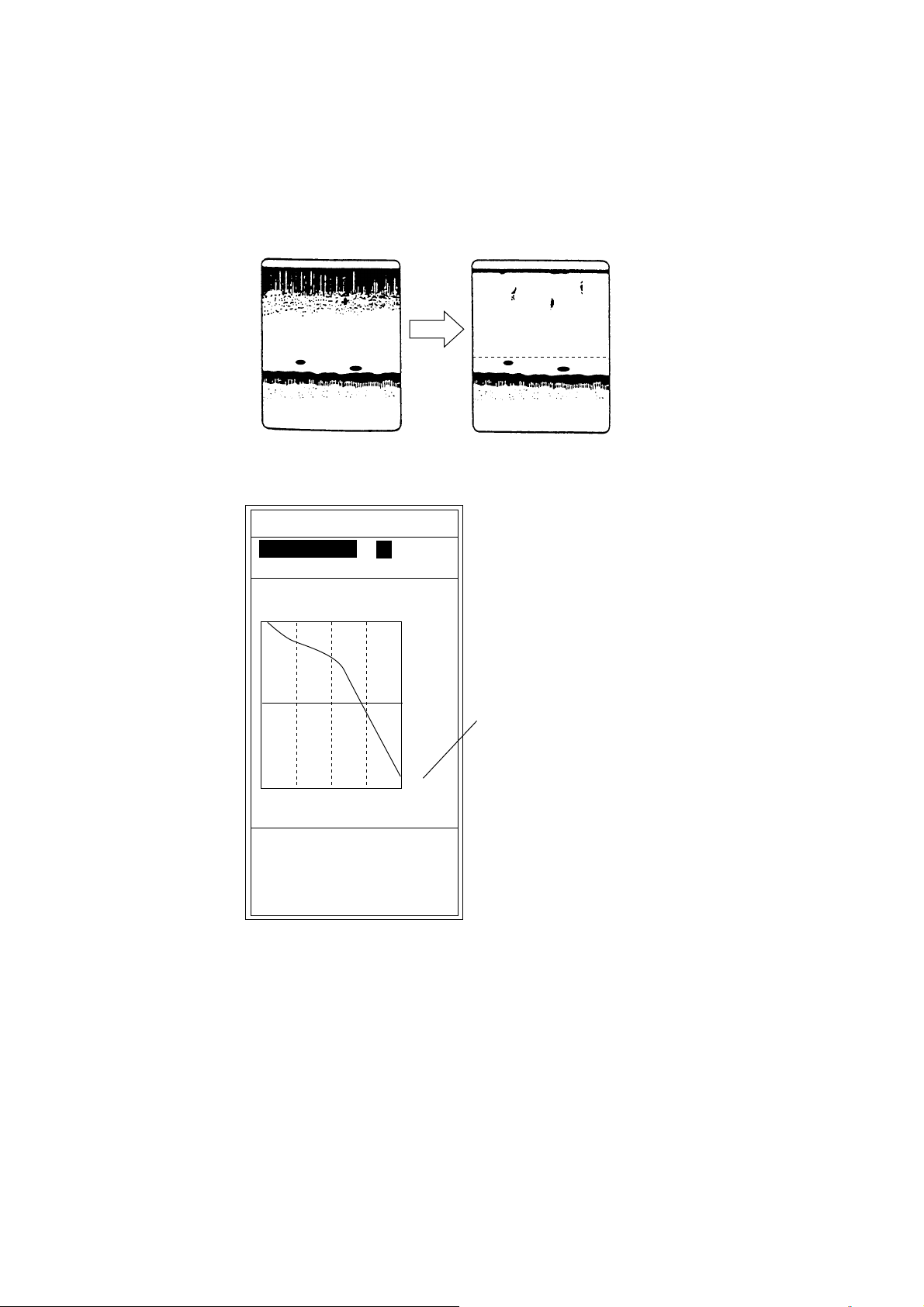
BOTTOM SEARCH
On the dual-frequency display, choose transducer which is to measure depth.
The choices are AUTO, low frequency and high frequency. “AUTO” gives priority
to high frequency transducer having greatest accuracy.
BOTTOM LEVEL
When the bottom depth readout is unstable, use this feature to stabilize it. The
setting range is –40 to 0.
1/1
5
Bottom-lock
display
4
0.0
LF
10
0
0
3
20
2
30
40
Set the bottom
search so these
vertical lines disappear.
21.7
1
m
0
Bottom
How to adjust bottom level
If this setting value is too small, fish echoes may be regarded as bottom, which
causes unstable depth readout.
AUTO MODE
Turns on/off the auto mode.
OFF: Turns off the auto mode. Gain, range and clutter may be adjusted
manually.
CRUISING: Suppresses weak echo es t o emphasize bottom echoes clearly. Use
this setting when going to a fishing ground.
FISHING: Displays weak echoes clearly. Use this setting for fishing.
In the auto mode, gain, display range and clutter are automatically adjus ted.
Gain is automatically adjusted so t he bottom echo is painted in reddish brown. (If
the gain appears to be too strong, it can be offset on t he TX/RX menu with
“GAIN ADJ.”) Display range is automatically adjusted to show the bottom echo
on the lower 1/2 of the screen. Clutter is automatically adjusted to suppress
weak echoes such as sediment in the water and plankton.
2-11
Page 42

2. MENU OPERATION
2.6 USER Menu
The USER menu sets up the user displays, user color and user clutt er, and
programs the [SHIFT /PROG] key. This menu can be shown by placing the
[FUNCTION] switch in the “PROG” position.
USER-1/2
<USER-1>
NAV DATA DISP : OFF
NAV DATA MODE : ALPHANUMERIC
<USER-2>
NAV DATA DISP : OFF
NAV DATA MODE : ALPHANUMERIC
SHIFT/PROG KEY : SHIFT
USER COLOR SETTING
USER
USER CLUTTER SETTING
Menu for user-preset mode setting.
[+]: Go to setting [EXIT]: Exit
USER menu
USER-1/2
Customizes the user displays.
<USER-1>
SCREEN LAYOUT
DISP MODE : [LF]+[HF]+[MIX]
ZOOM MODE : BOTTOM ZOOM *
TARGET ECHO: NORMAL
<USER-2>
SCREEN LAYOUT:
DISP MODE :
ZOOM MODE : BOTTOM ZOOM
TARGET ECHO: NORMAL
Select screen layout.
USER -1/2
:
[LF]Zm/Nor+[HF]Zm/Nor
2-12
[-/+]: Change set, [EXIT]: Exit
* = The setting is available when Zm (Zoom)
is selected at the DISP MODE field.
USER-1/2 menu
Page 43

2. MENU OPERATION
SCREEN LAYOUT
Chooses the screen division layout am ong t he patterns shown below.
The default settings are as follo ws:
USER-1:
USER-2:
( [LF]+[HF] +[MIX])
([LF]Zm/Nor+[HF]Zm/Nor)
DISP MODE
Chooses the picture to display in respective screen layout.
[HF]:Normal
[LF]:Normal
[HF]:Zoom
[LF]:Zoom
[MIX]:Normal
[HF]:Zm/Nor
[LF]:Zm/Nor
[LF]+[HF]
[LF]:Zm+[HF]:Zm
[HF]+[MIX]
[LF]+[MIX]
[LF]+[HF]:Zm/Nor
[LF]:Zm/Nor+[HF]
[LF]+[HF]+[MIX]
[LF]:Zm/Nor+[HF]:Zm/Nor
HF: high frequency LF: low frequency
NOR: normal ZM: zoom
MIX: mix
ZOOM MODE
Chooses the zoom mode to use.
BOTTOM LOCK BOTTOM ZOOM MARKER ZOOM DISCRIM-1/2 DISCRIM-1/3
Zoom mode choices
TARGET ECHO
Chooses the target echo from normal, surface, squid and deep sea. For details,
see page 3-10.
NORMAL SURFACE SQUID DEEP SEA
Target echo choices
NAV DATA DISP
Nav data may be displayed at the left or right half of the screen, or turned off.
2-13
Page 44

2. MENU OPERATION
NAV DATA MODE
Three nav data displays are available: alphanumeric, graphic1 and graphic2.
ALPHANUMERIC
The alphanumeric display provides position in latitude and longitude, course,
speed, depth, temperature, and range, bearing and cross-track error to the
destination waypoint. Appropriate sensors are required to show data other than
depth. If desired, you may enlarge one indication on one half of the screen.
Circumscribe the indication to enlarge by operating the [ ▲] or [▼] key, then
press the [+] key. To restore t he full nav data display, press t he [ - ] key.
POS
34°44.135’N
135°27.098’E
CSE SPD
135° 8.6
Cursor for choosing
data to enlarge
kt
DEP TMP
42.9ft 85.51
WP 001
RNG
BRG
XTE
79.03
135°
0.005
nm
nm
°F
Nav data display
GRAPHIC1
The GRAPHIC1 display mainly provides steering information. Appropriate
sensors are required.
Bearing to Destination Waypoint
Bearing*
Destination
Waypoint
Range to
Destination
Waypoint
Depth
* = Requires appropriate sensor.
W
1nm 1nm
WP
ABC
RNG
12.0
nm
DEP
69.4
ft
N
BRG
359
CSE
323
°
°
SPD
8.4
kt
TRIP
76.8
nm
TMP
85.51
°F
0
Course*
E
20
Cross-track Error
40
60
80
Speed*
Distance Run*
Note: Distance run may be
reset to zero by pressing
the [+] or [-] key for about
five seconds.
2-14
Water Temperature*
Graphic1 display
Page 45

2. MENU OPERATION
GRAPHIC2
The GRAPHIC 2 display provides a speedometer together with steering
information. Appropriate sensors are required.
Distance run since power was turned on
50
Speedometer*
Depth
Waypoint
Course
Waypoint Bearing
XTE
40
30
20
10
0
DEPTH
55.8ft
WPT: FOX1 35°23.119'N
122
CSE: 120
BRG: 135
XTE
0.50
nm
1 0.5
°
°
RNG
100.5nm
SPEED
TEMP
85.51°F
0
SHIFT/PROG KEY
TRIP
0
1182 nm
10.6 kt
20
°
46.970'E
1
0.5
Graphic2 display
40
60
80
Note: Distance run may be
reset to zero by pressing
the [+] or [-] key for about
five seconds.
Speed*
Water Temperature*
Position*
Waypoint Relative Bearing*
(In relation to course)
* = Requires appropriate sensor.
Chooses the function of the [S HIFT/PROG] key. The choices are shift, picture
advance, signal level, hue, white line, PRR level, bottom level, A-scope, auto
shift and auto mode.
Blue bar
SHIFT PIC ADVNC SIGNAL LEVEL HUE WHITE LINE
The blue bar shows the current cursor position in
relation to the option range.
This bar shifts with operation of [-] or [+] key.
SHIFT/PROG soft key program choices
2-15
Page 46

2. MENU OPERATION
USER COLOR SETTING
In addition to the standard and factory-programmed color sets, the user may set
and store display colors as desired.
COLOR NO. : BKGD
RED : 0 (0 15)
GREEN : 2
BLUE : 9
DEFAULT : NO
CUSTOM : NO
Color setting for 16-color presentation.
[-/+]: Change set, [EXIT]: Exit
USER COLOR SETTING
USER COLOR SETTING menu
1. Press the [-] or [+] key to show the color setting window. (In case of eight
colors, color is 1-6.)
BKGD ECHO1 ECHO2 ECHO3 ECHO4 ECHO5 ECHO6 ECHO7
Color setting window (16 colors)
2. Press the [-] or [+] key to select the color to change.
ECHO15
ECHO14
ECHO13
ECHO12
ECHO11
ECHO10
ECHO9
ECHO8
ECHO7
ECHO6
ECHO5
ECHO4
ECHO3
ECHO2
ECHO1
BKGD
Color bar (for 16 colors)
3. Press the [▲] or [▼] key to close the color setting window.
4. Press the [▼] key to select RED, GREEN or BLUE (level).
2-16
Page 47

2. MENU OPERATION
5. Press the [-] or [+] key to show the level setting window.
0
Level setting window
6. Press the [-] or [+] key to select color strength. The higher the number, the
darker the color.
7. Press the [▲] or [▼] key to close the level setting window.
8. Do steps 1-7 to set another color.
9. To use custom colors, select YES at CUSTOM.
10. To return to original color, select YES at DEFAULT.
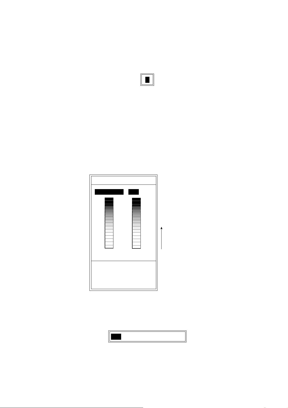
USER CLUTTER SETTING
The USER CLUTTER SETTING menu lets you emphasize weak to medium
strength echoes.
USER CLUTTER SETTING
COLOR-7 : 3 (1 14)
COLOR-6 : 3
COLOR-5 : 3
COLOR-4 : 3
COLOR-3 : 3
COLOR-2 : 3
COLOR-1 : 3
BACKGROUND : 3
DEFAULT : NO
When the value is not suitable,
weak level is automatically adjusted.
Set clutter level to be displayed.
[-/+]: Change set, [EXIT]: Exit
The larger the
setting, the wider
the ratio of the
color selected.
USER CLUTTER SETTING menu
1. Press the [▲] or [▼] key to select color or background to change. COLOR-7
is the strongest color.
2. Press the [-] or [+] key to show the setting window.
0
Setting window
2-17
Page 48

2. MENU OPERATION
3. Press the [-] or [+] key to set the level (1-14).
If…
you want to emphasize
COLOR-7 (reddish-brown, red)
you want to emphasize middle
color (yellow, green)
you want to remove the
weakest color
COLOR-7, COLOR-6: set large value.
COLOR-5 to COLOR-1: Set small value.
COLOR-7 to COLOR-5: Set small value.
COLOR-4 and COLOR-3: Set large value.
COLOR-2 and COLOR-1: Set small value.
COLOR-1: Set small value.
Then...
4. Press the [▲] or [▼] key to close the setting window.
5. Repeat steps 1 through 4 to set another color.
6. To use custom clutter settings, set the [FUNCTION] switch in the CLUTTER
position, then select CUSTOM from HF CURVE (LF CURVE).
To return to default settings, select YES at DEFAULT.
2-18
Page 49

3. SYSTEM MENU
3.1 SYSTEM Menu Operation
1. Rotate the [FUNCTION] switch fully clockwise to select MENU.
2. Press the [▲] key to select the menu title area.
3. Press the [+] key to choose SYSTEM to show the SYSTEM menu.
DISP ALM TX/RX E/S SYSTEM
SYSTEM SETTING
DRAFT SETTING
RANGE SETTING
TEMP SETTING
NAV DATA SETTING
TARGET ECHO
TEST MODE
DEFAULT SETTING
Menu for system setting.
[+]: Go to setting [EXIT]: Exit
System menu
4. Press the [▲] or [▼] key to select the item which you want to set.
5. Press the [+] key to show the sub menu.
6. Rotate the [FUNCTION] switch fully counterclockwise to select EXIT.
3-1
Page 50

3. SYSTEM MENU
3.2 SYSTEM SETTING Menu
The SYSTEM SETTING menu mainly sets picture layout options.
DISP ALM TX/RX E/S SYSTEM
SYSTEM SETTING
PICT ADV DIR : LEFT
DISP DIVISION :
DEPTH SCALE : RIGHT
DEPTH UNIT : ft
FREE SHIFT : OFF
AUTO SHIFT : OFF
ZOOM MODE : BOTTOM LOCK
LANGUAGE : ENGLISH
Select picture scrolling direction.
[-/+]: Change set, [EXIT]: Exit
SYSTEM SETTING menu
PICT ADV DIR
Chooses picture advance direction: right or left which advances the picture in
both right and left directions f r om the screen center.
DISP DIVISION
Sets display division for the dual frequency picture.
, vertical; , horizontal.
DEPTH SCALE
Chooses where to position the depth scale; right, center or off.
DEPTH UNIT
Chooses unit of depth measurement; met ers, feet, fathoms, hiro (Japanese),
passi/braza. Note that the Japanese characters for hiro appear when using hiro.
FREE SHIFT
3-2
Sets shift value independently for each range (ON) or commonly for all ranges
(OFF).
Page 51

3. SYSTEM MENU
AUTO SHIFT
Turns automatic depth shift on or off. The automatic shift function automatically
locates the bottom trace on the lower half of the screen; the range window jumps
up where the bottom trace rises over the center of the screen and jumps down
when it reaches the bottom of the screen. AUTO appears at the top right corner
of the screen when the auto shift function is on. Note that the [+] and [-] keys are
inoperative when the automatic shift function is turned on.
1/2
3/4
Range changes automatically to
locate the bottom on the lower half
of screen.
3/4
The equipment shifts to a deeper
range when the bottom comes to
the lower edge of the depth scale.
Automatic shift concept
ZOOM MODE
Chooses the zoom mode for the ZOOM position of the [FUNCTION] switch. The
choices are bottom lock, bottom zoom, marker zoom, discrimination-1/2 and
discrimination-1/3.
LANGUAGE
Chooses the language: ENGLISH or other languages. To switch language,
select language desired, then rotate the [FUNCTION] switch fully
counterclockwise to select EXIT.
3-3
Page 52

3. SYSTEM MENU
3.3 DRAFT SETTING Menu
The DRAFT SETTING menu sets draft value, when you require depth below the
surface.
DISP ALM TX/RX E/S SYSTEM
DRAFT SETTING
<High Frequency>
DRAFT : +0.0 ft (-15 +90)
<High Frequency>
DRAFT : +0.0 ft (-15 +90)
Set draft value if depth below surface
is needed.
[-/+]: Change set, [EXIT]: Exit
DRAFT SETTING menu
DRAFT
Sets draft depth for low and high frequencies.
3-4
Page 53

3.4 RANGE SETTING Menu
The RANGE SETTING m enu presets the range chosen with the [RANGE]
control.
DISP ALM TX/RX E/S SYSTEM
RANGE SETTING
RANGE1 : 30 ft (16 6000)
RANGE2 : 60 ft
RANGE3 : 120 ft
RANGE4 : 250 ft
RANGE5 : 500 ft
RANGE6 : 1000 ft
RANGE7 : 1600 ft
RANGE8 : 3000 ft
M/Z RANGE : 16 ft (16 600)
B/L RANGE : 16 ft
SPLIT RANGE: OFF
3. SYSTEM MENU
Set preset range scales.
[-/+]: Change set, [EXIT]: Exit
RANGE SETTING menu
RANGE1-RANGE8
Presets basic ranges for the [RANGE] switch. Ranges must be set from shallow
to deep, and a range may not be lower than a preceding one. (Setting ranges:
5-2000 m, 16-6000 ft, 2-1200 fa, 4-1600 hiro, 3-1200 P/B)
M/Z RANGE
Sets display range of marker zoom and bottom zoom pictures. (Setting ranges:
5-200 m, 16-600 ft, 2-120 fa, 4-160 hiro, 3-120 P/B)
Note: For the vertical split screen, halve the above values.
B/L RANGE
Sets display range of bottom-lock, discrim-1/2, discrim-1/3 pict ure. (5-200 m,
16-600 ft, 2-120 fa, 4-160 hiro, 3-120 P/B)
Note: For the vertical split screen, halve the above values.
3-5
Page 54

3. SYSTEM MENU
SPLIT RANGE
Select ON to set range for low frequency and high frequency individually.
1. Rotate the [RANGE] switch to show RANGE (LF or HF) window.
RANGE [LF]
30 ft
60 ft
120 ft
250 ft
500 ft
1000 ft
1600 ft
3000 ft
Switch [LF] and [HF] by
pressing the [RANGE]
switch.
RANGE [HF]
30 ft
60 ft
120 ft
250 ft
500 ft
1000 ft
1600 ft
3000 ft
Range window
2. Press the [RANGE] switch within five seconds to display the RANGE (LF)
window or RANGE (HF) window whichever desired.
3. Rotate the [RANGE] switch to select the range desired.
3-6
Page 55

3.5 TEMP SETTING Menu
The TEMP SETTING menu sets up the water temperature sensor (FURUNOsupplied sensor only).
DISP ALM TX/RX E/S SYSTEM
TEMP SETTING
TEMP UNIT : °F
TEMP INPUT : SENSOR
TEMP ADJUST : +0.00°F (-20 +20)
TEMP OUTPUT : ON
TEMP READOUT: ON
TEMP GRAPH : OFF
TEMP COLOR : STD
Select temperature unit.
3. SYSTEM MENU
[-/+]: Change set, [EXIT]: Exit
TEMP SETTING menu
TEMP UNIT
Chooses unit of temperature m easure, Celsius or Fahrenheit.
TEMP INPUT
Chooses source of water temperature data; sensor (FURUNO), or NMEA.
TEMP ADJUST
Offsets water temperature indication to improve accuracy. Effective only for
FURUNO-supplied water temperature sensor.
TEMP O UTPU T
Turn on/off water temperature data output.
TEMP READOUT
Turns on/off water temperature indication.
TEMP GRAPH
Turns on/off water temperature graph and chooses graph scale.
OFF: No water temperature graph
3-7
Page 56

3. SYSTEM MENU
TEMP COLOR
Chooses the color of the temperature graph (standard, white, red, black, yellow).
Note: Standard means the fifth color from the bottom of the color bar, including
background color in 16-color display; third color in 8-color display. Ye llow
means tenth (8-color display: sixth) color from the bot tom of the color bar.
3.6 NAV DATA SETTING Menu
The NAV DATA SETTING menu chooses source of position and heading data.
DISP ALM TX/RX E/S SYSTEM
NAV DATA SETTING
SPEED UNIT : kt
SPEED INPUT : SENSOR
SPEED ADJUST : +0% (-50 +50)
SPEED OUTPUT : ON
SPEED INFO : OFF
NMEA VERSION : Ver 2.0
NAV DATA : AUTO
COURSE : TRUE
TLL OUTPUT : OFF
Select speed unit.
[-/+]: Change set, [EXIT]: Exit
NAV DATA SETTING menu
SPEED UNIT
Chooses unit of speed measurement from knot, kilometer and statute
miles-per-hour.
SPEED INPUT
Chooses source of speed data, sensor or NMEA.
SPEED ADJUST
3-8
Further refines speed data accuracy.
SPEED OUTPUT
Turns speed data output on/off.
Page 57

3. SYSTEM MENU
NMEA VERSION
Chooses NMEA version of external navigator; Ver 1.5, Ver 2.0, Ver. 3.0 or
SPECIAL. If you are not sure of version number try both and select which one
successfully receives data. SPECIAL outputs the depth data at the rate of 600
bps.
NAV DATA
Chooses source of navigation data (NMEA talker); GPS, Loran C, Loran A,
Decca, DR or AUTO. Select AUTO when more than one talker data is input. The
order of priority is GPS, Loran C, Loran A, Decca, DR.
COURSE
Chooses heading reference (for heading data output from navigator); TRUE or
MAG (magnetic bearing).
TLL OUTPUT
Enables/disables output of L/L position to a navigation plotter when the
[MARKER/TLL] key is pressed.
3-9
Page 58

3. SYSTEM MENU
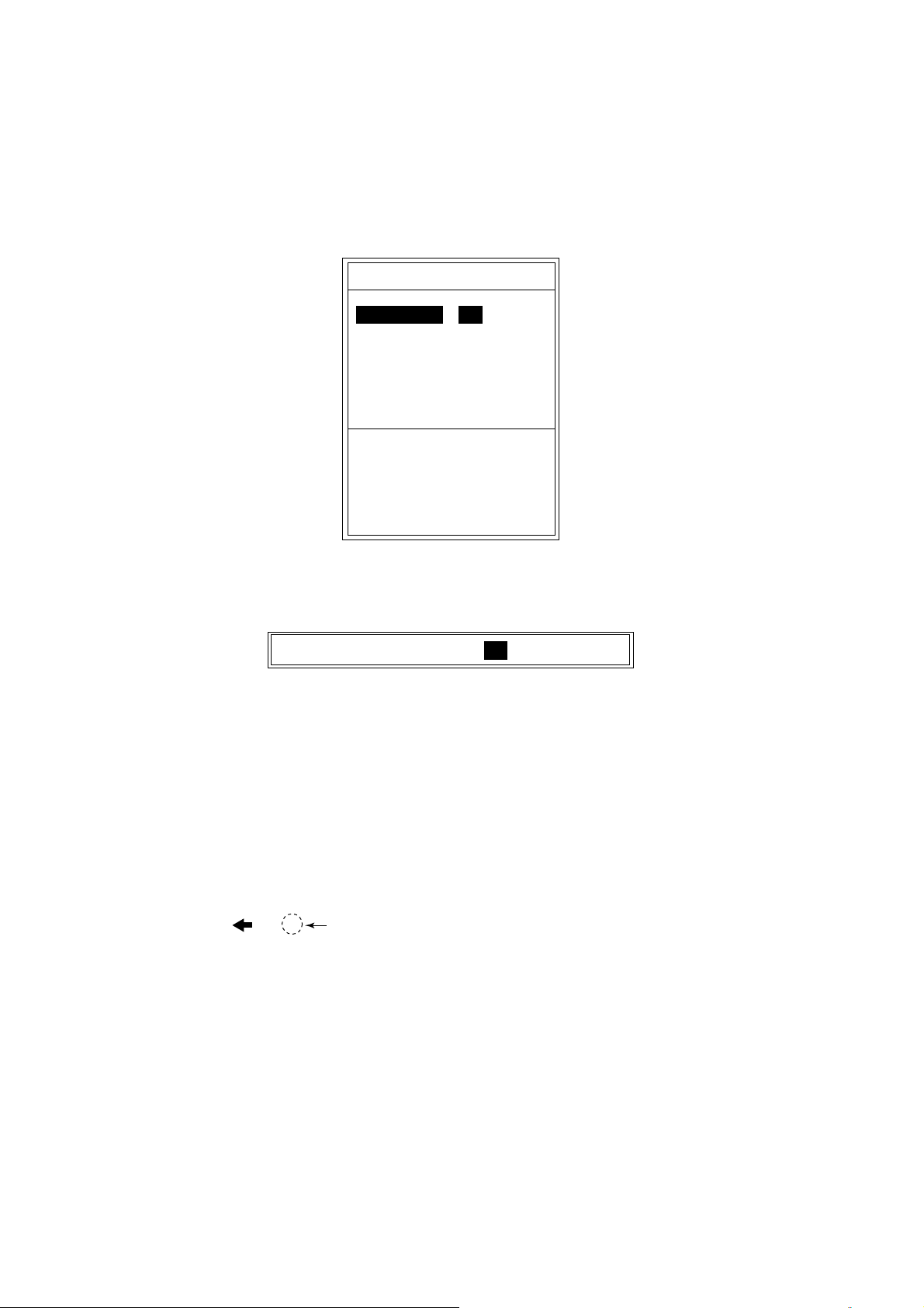
3.7 TARGET ECHO Menu
The TARGET ECHO menu sets fishing objective. Four choices are available:
NORMAL, SURFACE, SQUID and DEEP SEA.
DISP ALM TX/RX E/S SYSTEM
TARGET ECHO
TARGET ECHO : NORMAL
Select target echo to optimize
sounding parameters.
[-/+]: Change set, [EXIT]: Exit
TARG ET ECHO menu
TARGET ECHO
Sets up the equipment according to fishing objective
NORMAL: For general fishing.
SURFACE: For detecting surface fish. Pulse repetition rate is higher t han
“NORMAL” on 1 kW and 2 kW transducers (only those transducers
registered on the menu).
SQUID: For detecting squid and other individual fish. T he items below are
automatically set as follows:
TX pulselength: Short 1
Echo stretch: ON
Smoothing-1: OFF
DEEP SEA: Same as GENERAL.
3-10
Page 59

4. INTERPRETING THE DISPLAY
This section provides, using typical exam ples, the information necessary for
interpreting the display.
Minute marker
Surface
noise
Color bar
Bottom
49.6
Minute Marker: The minute marker displays a minute worth of time with two
colored bars, each bar 30 seconds in time. It is useful for estimating elapsed
time.
4.1 Color Bar
1/1
m
Typical display
LF
0.0
20
40
60
80
0
0
Zero line
Fish school
The color bar shows the relation between echo intensit y an d echo color on the
screen. The top color (reddish-brown) is the strongest color and the lower colors
the weakest. The bar can be used as a reference to estimate density of a fish
school, fish species and hardness of the bottom. The background color can be
selected on the menu screen.
STRONG
REDDISH-BROWN
RED
ORANGE
YELLOW
GREEN
LIGHT-BLUE
BLUE
DEEP BLUE
WEAK
No Signal
49.6
m
Color bar
4-1
Page 60

4. INTERPRETING THE DISPLAY
4.2 Zero Line
The zero line represents the transducer’s position. It moves off the screen when
a shifted range is used, or is shown at draft depth when ship’s draft is entered.
Zero Line
Range shifted
Zero line
4.3 Bottom Echoes
Bottom echoes are normally strongest and displayed in reddish-brown or red,
but colors and width will vary with bottom material, depth, sea condition,
installation, frequency, pulselength and sensitivity.
A hard and rough bottom appears with a longer tail because it reflects more of
the ultrasonic pulse. Because of their stronger return, shallow echoes appear
wider than deep ones even when all bottom conditions are equal. Also, a longer
bottom tail appears on slopes because of the difference in traveling time at both
edges of the beam angle. In the rugged bottom, echoes are reflected on many
different planes, overlapping to present a 3D effect.
Color difference
Second bottom
echo
Rugged
bottom
4-2
Bottom material and bottom profile
Page 61

4. INTERPRETING THE DISPLAY
The nature of the bottom is known from the intensity and length of the bottom tail.
Generally, when observing the bottom nature, the lower sounding frequency is
used, the pulselength is set to long, and the gain setting is not disturbed. In the
hard and craggy bottom, the bottom appears more reddish and with a long tail.
However, the bottom with sediment may give a short tail if a low frequency
sounding is used.
Rock base
Mud & sand
Bottom nature
4.4 Fish School Echoes
Fish quantity can be estimated to a certain extent from fish echoes on the screen
if fish school size and fish school density are kept in mind.
Usually the size of fish echoes on the screen is proportional to the actual size of
the fish school. However, if two fish echoes appear at different depths with the
same size, the fish school at shallower depth is smaller because the ultrasonic
beam widens as it propagates and a fish school in deep water is displayed
larger.
Deep fish school sounding time
Shallow fish school sounding time
Large
Size of
fish school
school
Small
school
Fish school size Difference of fish school sounding times
School depth
and sounding
time
4-3
Page 62

4. INTERPRETING THE DISPLAY
If two fish schools appear with the same color at different depths, the one in
deeper water is denser because the ultrasonic wave attenuates as it propagates
and the fish school in deep water tends to be displayed in a weaker color.
Less Reddish
(Sparse echo)
Fish Echo
Reddish
(Dense echo)
Fish school density
4.5 Other Echoes
4.5.1 Plankton
A plankton layer, a likely place to find fish, is displayed in green or blue dots. It
usually descends in the day and rises at night.
Plankton
Fish School
Difference in
signal strength
Weak Echo
Strong
Echo
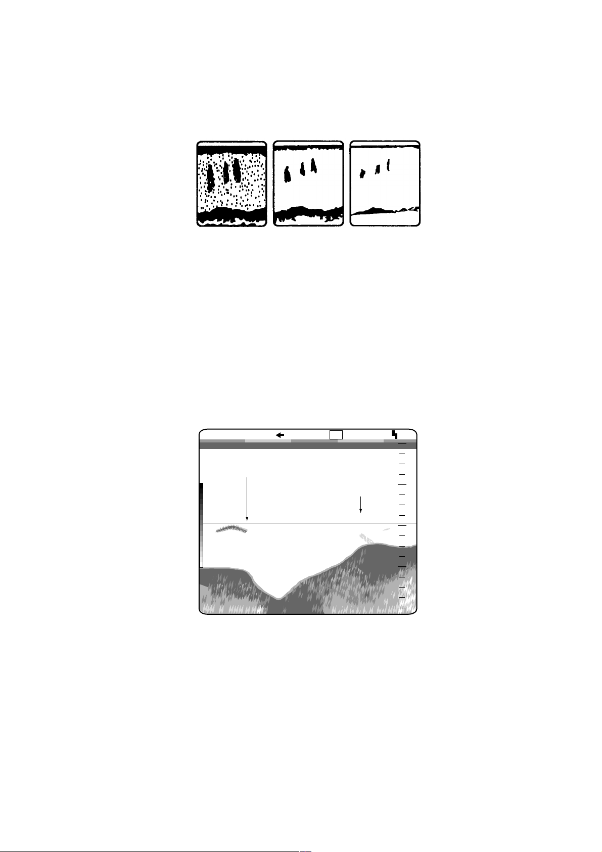
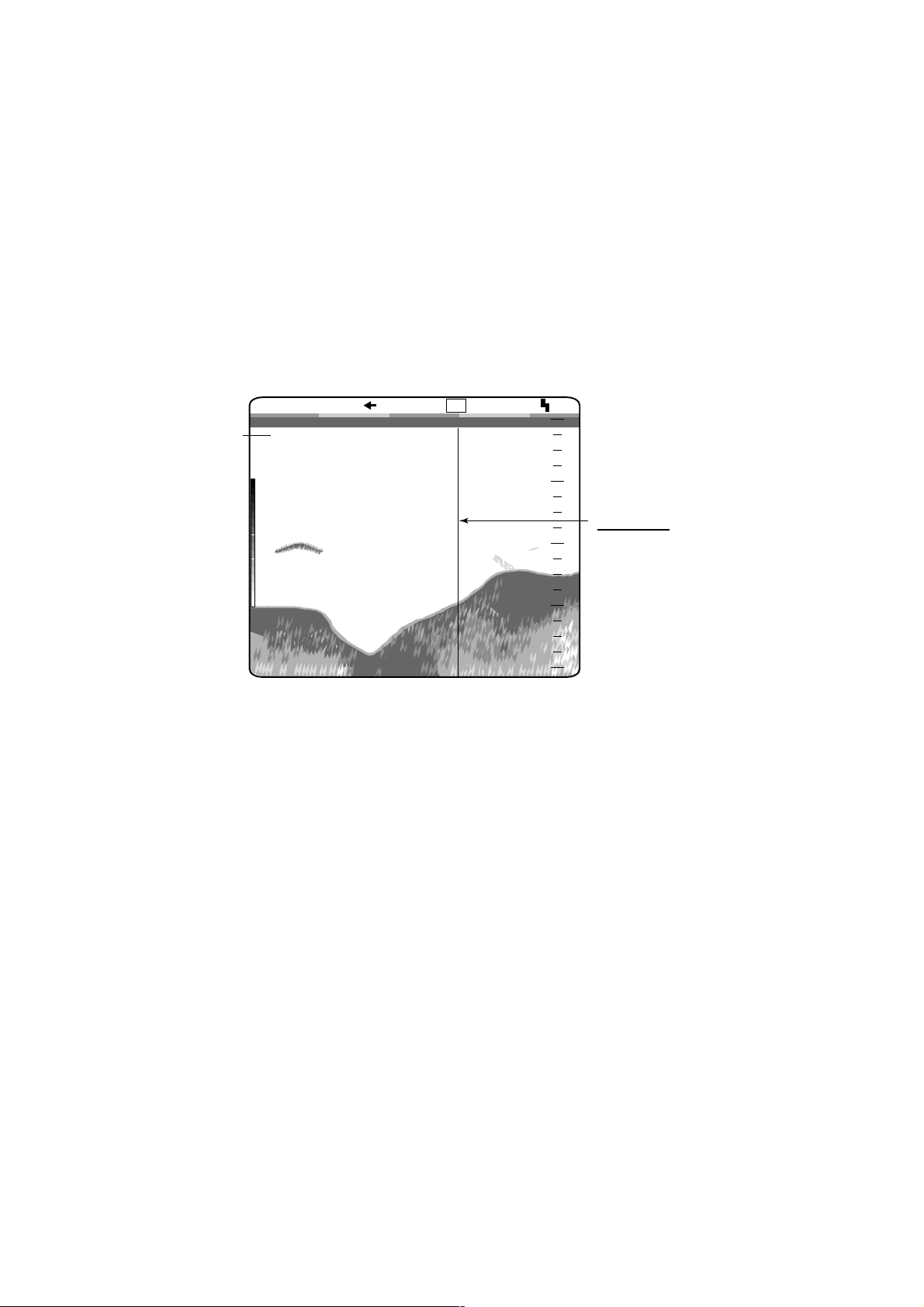
4.5.2 Current rip
A current rip develops when two ocean currents of different speeds, directions
and water temperatures meet. Its on-screen appearance is as shown below.
Plankton
Current Rip
Current rip
4-4
Page 63

4.5.3 Surface noise
When the sea is rough or the ship passes over a wake, surface noise may
appear at the top of the screen. It can be suppressed with the CLUTTER
function.
Surface Noise
4.5.4 Aerated water
When the sea is rough or the ship makes a quick turn, gaps in the bottom echo
on the screen may appear. This is caused by air bubbles which block
propagation of the sound wave. Generally low frequency ultrasonic waves are
interrupted more easily than high ones.
4. INTERPRETING THE DISPLAY
Surface noise
Ultrasonic wave
blocked by
aerated water
4.5.5 False image
Every time the ultrasonic pulse is transmitted, some radiation escapes on each
side of the beam, called “side lobes.” Echoes from side lobes show on the
display as false images as below.
False Image
Aerated water
Main
Lobe
Side
Lobe
False image
4-5
Page 64

4. INTERPRETING THE DISPLAY
This page is intentionally left blank.
4-6
Page 65

5. MAINTENANCE, TROUBLESHOOTING
WARNING
ELECTRICAL SHOCK HAZARD
Do not open the equipment.
Only qualified personnel
should work inside the
equipment.
5.1 Maintenance
Regular maintenance is important for continued perf or mance. Import ant points to
be checked fr om time to time are show n below.
Maint enanc e pr ogram
Check point Action Interval
Transducer cable If conductors are exposed, replace cable. Monthly
Power cable plug,
transducer cable
plug
Grounding If corroded, clean. Monthly
Ship’s mains
voltage
Display uni t
cleanliness
Transducer
cleanliness
If loosened, secure tightly. Monthly
If out of ra tings, correct problem. Monthly
Dust or dirt may be removed with a soft
clot h. Water-d iluted mild detergent m ay be
used if desired. DO NOT use chemical
cleaners to clean the display unit; they may
remove paint and mark ings. Use special care
when cleaning the LCD, since it scratches
easily.
Marine life on the transducer will resu lt in a
gradual decrease in sensitivity. Check the
transduc er fac e ea ch ti m e the boat is
dry-docked. Carefully remove any marine life
with piece of w ood or f ine sandpaper.
Monthly
At dry-dock
5-1
Page 66

5. MAINTENANCE, TROUBLESHOOTING
5.2 Fuse Replacement
A 5A fuse (type: FGBO-A 5A AC125V) in the power cable protects the equipment
against overcurrent, reverse polarity of the ship’s mains and internal fault. If the fuse
blows find the cause before replacing it. Contact your dealer about replacement. (A
7A fuse (type: FGMB 7A 125V) also is contained inside the display unit. Contact
your dealer about its replacement.)
CAUTION
Use the proper fuse.
Use of a wrong fuse can cause fire or
damage the equipment.
5.3 Troubleshooting
This section provides simple troubleshooting procedures which the user may
follow to restore normal operation.
Troubleshooting
If… Then…
there are no echoes but
the depth scale appears
there is no zero line or
zero line is not in correct
position
you suspect poor or low
sensitivity
the bottom is traced in
zigzag pattern or you
experience occasional
loss of echo
there is no depth readout • check to see if bottom is present on the normal picture range.
automatic shift is
inoperative
noise appear
intermittently
there is noise and
interference
• check if the transducer is properly connected.
• check if the range shifted. (Zero line does not appear when
the range is shifted.)
• press the [-] key so as the scale starts from 0.
• check that the [GAIN] control is properly set.
• the sea may be rough. Bottom is traced zigzag when the sea
is rough.
• own boat may have passed over other boat’s wake, which
blocks propagation of sound wave.
• check if bottom echo is painted in red, reddish-brown.
• check if bottom echo is painted in red, reddish-brown.
• check if the cables of pulse generating equipment are near
the equipment.
• check that GAIN and CLUTTER are properly adjusted.
• check the setting of the noise limiter.
• check the equipment’s ground.
5-2
Page 67

5.4 Diagnostic Test
The diagnostic test checks the equipment for proper operation.
1. Rotate the [FUNCTION] switch fully clockwise to select MENU.
2. Press the [▲] key to select the menu title area at the top of screen.
3. Press the [+] key to select SYSTEM.
4. Press the [▲] or [▼] key to select TEST MODE.
5. Press the [+] key to open the TEST menu.
DISP ALM TX/RX E/S SYSTEM
TEST MODE
DIAGNOSTICS : NO
TEST PATTERN: NO
HI FREQ
HI FREQ : 200 kHz : 200 kHz
LOW FREQLOW FREQ : 50 kHz : 50 kHz
5. MAINTENANCE, TROUBLESHOOTING
Press and hold [MARKER] key more than
3 sec to exit from TEST MODE.
Menu for diagnostics.
[-/+]: Change set, [EXIT]: Exit
Test menu
6. Press the [+] key twice to select YES in the setting window.
[ ] : YES[ ] : NO
Test setting window
7. The ROM, SRAM, DRAM and NMEA check results appear. Water
temperature and speed also appear if appropriate sensor is connected.
Program No. 0252307-03.XX
ROM OK
SRAM OK
DRAM OK
NMEA OK*
Temp. SENSOR +85.5˚F
Speed SENSOR 8.0 kt
ROM, SRAM, DRAM and NMEA test
results are shown as OK or NG (No Good).
O O O 238
O 8 O 6
* O O O 255
Press and hold [MARKER] key more than 3 sec to exit.
XX: Version No.
*: Requires special cable to check.
Panel window
For testing controls.
See next page.
Diagnosti c test results
5-3
Page 68

5. MAINTENANCE, TROUBLESHOOTING
5.4.1 Panel Test
The “panel window” at the bottom of the diagnostics display is used to check
keys and controls.
1. Press any key except the [PWR] key. The pressed key’s on-screen location
changes from 0 to 1 when the key is pressed.
2. Operate each control. The figure on the screen changes as below.
[FUNCTION]: 1 to 8
[RANGE]: 0 to 20
[MODE]: 1 to 7
[GAIN]: 0 to 255
3. To quit the diagnostic test, press the [MARKER/TLL] key more than three
seconds to return to the SYSTEM menu, then rotate the FUNCTION switch
fully counterclockwise to select EXIT.
5-4
Page 69

5.5 Test Pattern
The test pattern tests for proper display of colors.
1. Rotate the [FUNCTION] switch fully clockwise to select MENU.
2. Press the [▲] key to select the menu title area at the top of the screen.
3. Press the [+] key to select SYSTEM.
4. Press the [▲] or [▼] key to select TEST MODE.
5. Press the [+] key.
6. Press the [+] key to select TEST PATTERN.
7. Press the [+] key twice to select YES in the dialog box.
5. MAINTENANCE, TROUBLESHOOTING
[ ] : YES[ ] : NO
Test pattern selection dialog box
8. Press the [+] key successively to change the test pattern, in the sequence
below.
16 tones
of RED
16 tones
of GREEN
16 tones
of BLUE
BLUE GREENBLACK
WHITE
RED
Test pattern sequence
9. Press the [MARKER/TLL] key more than three seconds to return to the
SYSTEM menu.
10. Rotate the [FUNCTION] switch fully counterclockwise to select EXIT.
5-5
Page 70

5. MAINTENANCE, TROUBLESHOOTING
5.6 Restoring Default Settings
All menu options can be restored to their default settings. For your reference all
default settings are shown in the menu tree at the back of this manual.
Note: User color setting, language, target echo setting and user clutt er set ting
are not disturbed.
1. Rotate the [FUNCTION] switch fully clockwise to select MENU.
2. Press the [▲] key to select the menu titles at the top of the menu.
3. Press the [+] key to select SYSTEM.
4. Press the [▼] key to select DEFAULT SETTING.
5. Press the [+] key to show the DEFAULT SETTING menu.
DISP ALM TX/RX E/S SYSTEM
DEFAULT SETTING
DEFAULT SET : NO
[-/+]: Change set, [EXIT]: Exit
Default setting menu
6. Press the [+] key twice to select YES in the selection window.
[ ] : YES[ ] : NO
Default setting selection window
7. A beep sounds while the memory is being cleared.
8. After the beep stops, rotate the [ F UNCTION] switch fully counterclockwise to
select EXIT.
5-6
Page 71

A
APPENDIX
Menu Tree
[FUNCTION] switch
CLUTTER
TVG
SIG LEVEL
ADVANCE/A-SCOPE PIC ADVNC (STOP, 1/16, 1/8, 1/4, 1/2, 1/1, 2/1, 3/1, 4/1)
NL HF FREQ ADJ (-10.0-+10.0% , +0.0%)
HF CLUTTER (0-5, 2)
HF CURVE (STD, LINEAR, CUSTOM)
LF CLUTTER (0-5, 2)
LF CURVE (STD, LINEAR, CUSTOM)
HF TVG LEV (0-10, 5)
HF TVG DIST (100ft-3000ft, 600ft)
LF TVG LEV (0-10, 5)
LF TVG DIST (100ft-3000ft, 600ft)
SIGNAL LEV (OFF, 16 colors: 1-9, 8 colors: 1-4)
A-SCOPE (OFF, ON)
*1
HF NOISE LIM (OFF, N1, N2, N3)
LF FREQ ADJ (-10.0-+10.0%, +0.0%)
LF NOISE LIM (OFF, N1, N2, N3)
Underline: default setting
*1: The setting range is limited
because the following frequencies
can not be used:
54-64 kHz, 112-122 kHz, 171-181 kHz
(Continued on the next page)
-1
Page 72

APPENDIX
A
(Continued from previous page)
PROG USER-1
SCREEN LAYOUT ( )
DISP MODE
ZOOM MODE (BOTTOM LOCK, BOTTOM ZOOM, MARKER ZOOM,
DISCRIM-1/2, DISCRIM-1/3)
TARGET ECHO (NORMAL, SURFACE, SQUID, DEEP SEA)
([HF]:Normal, [LF]: Normal,
[HF]:Zoom, [LF]:Zoom, [MIX]:Normal)
([HF]:Zm/Nor, [LF]: Zm/Nor,
[LF]+[HF], [LF]Zm+[HF]Zm, [HF]+[MIX], [LF]+[MIX])
([LF]+[HF]:Zm/Nor, [LF]: Zm/Nor+[HF], [LF]+[HF]+[MIX])
([LF]Zm/Nor+[HF]Zm/Nor)
(Continued on next page)
USER-2
SCREEN LAYOUT (Same as USER-1, default setting: )
DISP MODE (Same as USER-1, default setting: [LF]Zm/Nor+[HF]Zm/Nor)
ZOOM MODE (Same as USER-1, default setting: BOTTOM ZOOM)
TARGET ECHO (Same as USER-1, default setting: NORMAL)
USER-1, USER-2 NAV DATA DISP (OFF, LEFT, RIGHT)
NAV DATA MODE* (ALPHANUMERIC, GRAPHIC1,
GRAPHIC2)
* = When LEFT or RIGHT is selected at NAV DATA DISP.
SHIFT/PROG KEY (SHIFT, PIC ADVNC, SIGNAL LEVEL, HUE, WHITE LINE,
PRR LEVEL, BOTTOM LEVEL, A-SCOPE, AUTO SHIFT,
AUTO MODE)
-2
Page 73

A
(Continued from previous page)
USER COLOR SETTING
APPENDIX
COLOR NO. (BKGD, 16 colors: ECHO1-ECHO15,
8 colors: ECHO1-ECHO7)
RED (0-15, 0)
GREEN (0-15, 2)
BLUE (0-15, 9)
DEFAULT (NO, YES)
CUSTOM (NO, YES)
MENU
USER CLUTTER SETTING
DISP
COLOR-7 (1-14, 3)
COLOR-6 (1-14, 3)
COLOR-5 (1-14, 3)
COLOR-4 (1-14, 3)
COLOR-3 (1-14, 3)
COLOR-2 (1-14, 3)
COLOR-1 (1-14, 3)
BACKGROUND (1-14, 3)
DEFAULT (NO, YES)
NO. OF COLORS (8, 16)
HUE (CUSTOM, STD, HUE1-7)
BACKGROUND (BLACK, DARK BLUE, BLUE,
LIGHTBLUE, WHITE)
WHITE LINE (OFF, 1-10)
DEPTH INFO (OFF, STD, LARGE, RIGHT)
MARKER SELECT (VRM, WHITE MARKER)
ZOOM MARKER (OFF, ON)
DISPLAY DATA (OFF, L/L, TD, TIMER, GAIN, R/B,
COURSE)
SCROLL TIME (OFF, ON)
ECHO STRETCH (OFF, ON)
SMOOTHING-1 (OFF, 1-4, 3)
SMOOTHING-2 (OFF, ON)
ALM BOTTOM ALARM (OFF, ON)
ALARM DEPTH (0-6000ft, 0ft)
ALARM ZONE (1-6000ft, 10ft)
FISH ALARM (OFF, FISH, BTM-FISH)
ALARM DEPTH (FISH: 0-6000ft, 0ft)
(BTM-FISH: 0.0-600.0ft, 0.0ft)
ALARM ZONE (FISH:1-6000ft, 10ft)
(BTM-FISH:0.1-600.0ft, 1.0ft)
ALARM LEVEL (MIN, MID, MAX)
TEMP ALARM (OFF, WITHIN RANGE, OUT OF RANGE)
TEMP LIMIT (20.00-95.00, 65.00°F)
ALARM ZONE (0.01-30.00, 1.00°F)
(Continued on next page)
-3
Page 74

APPENDIX
A
(Continued from the previous page)
TX/RX
E/S
SYSTEM
PRR LEVEL (0-20, S, 20)
STC (0-10, 0)
GAIN ADJ (-38-+12, +0)
RX BAND (NARROW, STD, WIDE)
TX PULSE (SHORT1, SHORT2, STD, LONG, MANUAL)
PULSE LENGTH (0.2msec-5.0msec, 0.2msec)
FREQ CHOICE (Set frequency of high and low frequencies.)
PWR REDUCTION (OFF, ON)
BOTTOM SEARCH (AUTO, LF, HF)
BOTTOM LEVEL (+0, -40 to +0)
AUTO MODE (OFF, CRUISING, FISHING)
SYSTEM SETTING
HF and LF should be set.
PICT ADV DIR (LEFT, RIGHT)
DISP DIVISION ( , )
DEPTH SCALE (RIGHT, CENTER, OFF)
DEPTH UNIT (m, ft, fa, hiro, P/B)
FREE SHIFT (ON, OFF)
AUTO SHIFT (ON, OFF)
ZOOM MODE (BOTTOM LOCK, BOTTOM ZOOM,
MARKER ZOOM,DISCRIM-1/2, DISCRIM-1/3)
LANGUAGE (ENGLISH, OTHER)
DRAFT SETTING DRAFT (+0.0, -15 to +90. Sets draft depth for both
high and low frequencies.)
RANGE SETTING
(Continued on the next page)
RANGE1 (16-6000ft, 30ft)
RANGE2 (16-6000ft, 60ft)
RANGE3 (16-6000ft, 120ft)
RANGE4 (16-6000ft, 250ft)
RANGE5 (16-6000ft, 500ft)
RANGE6 (16-6000ft, 1000ft)
RANGE7 (16-6000ft, 1600ft)
RANGE8 (16-6000ft, 3000ft)
M/Z RANGE (16-600ft, 16ft)
B/L RANGE (16-600ft, 16ft)
SPLIT RANGE (OFF, ON)
-4
Page 75

(Continued from previous page)
APPENDIX
TEMP SETTING
NAV DATA SETTING
TEMP UNIT (°C, °F)
TEMP INPUT (SENSOR, NMEA)
TEMP ADJUST (+0.00°F, -20 - +20)
TEMP OUTPUT (ON, OFF)
TEMP READOUT (OFF, ON)
TEMP GRAPH (OFF, NARROW, STD, EXPAND)
TEMP COLOR (STD, WHITE, RED, BLACK, YELLOW)
SPEED UNIT (kt, km/h, MPH)
SPEED INPUT (SENSOR, NMEA)
SPEED ADJUST (+0%, -50 - +50%)
SPEED OUTPUT (OFF, ON)
SPEED INFO (OFF, ON)
NMEA VERSION (Ver 1.5, Ver 2.0, Ver 3.0, SPECIAL)
NAV DATA (LC, LA, DECCA, GPS, DR, AUTO)
COURSE (TRUE, MAG)
TLL OUTPUT (OFF, ON)
TARGET ECHO TARGET ECHO (NORMAL, SURFACE, SQUID, DEEP SEA)
TEST MODE DIAGNOSTICS (NO, YES)
TEST PATTERN (NO, YES)
DEFAULT SETTING DEFAULT SET (NO, YES)
A-5
Page 76

APPENDIX
A
Screen Division
The screen may be divided as below with SCREEN LAYOUT on the USER-1/2 sub menu of
the USER menu.
Full screen
HIGH
NORMAL
[HF]: Normal
LOW
ZOOM
[LF]: Zoom
LOW
NORMAL
[LF]: Normal [HF]: Zoom
MIX
NORMAL
[MIX]: Normal
HIGH
ZOOM
-6
Page 77

A
Halves screen
APPENDIX
O
M
H
O
O
M
L
N
O
R
M
A
L
Z
M
I
X
N
O
R
LOW
NORMAL
LOW
ZOOM
HIGH
ZOOM
LOW
ZOOM
MIX
NORMAL
LOW
NORMAL
H
Z
O
O
M
L
N
O
R
M
A
L
H
N
R
A
L
H
N
O
R
M
A
L
[HF]: Zm/Nor [LF]: Zm/Nor
H
N
O
R
M
A
L
[LF]+[HF] [LF]:Zm+[HF]:Zm
M
I
X
N
O
R
HIGH
NORMAL
HIGH
ZOOM
HIGH
NORMAL
LOW
NORMAL
MIX
NORMAL
HIGH
NORMAL
L
Z
O
O
M
L
Z
O
O
M
L
N
O
R
M
A
L
[HF]+[MIX]
[LF]+[MIX]
-7
Page 78

APPENDIX
A
Thirds screen
L
N
O
R
M
A
L
L
N
O
R
M
A
L
H
H
N
O
Z
R
O
M
O
M
H
N
O
R
M
A
L
[LF]+[HF]: Zm/Nor [LF]: Zm/Nor+[HF]
M
I
X
N
O
A
R
L
[LF]+[HF]+[MIX]
Fourths screen
HIGH
NORMAL
HIGH
ZOOM
LOW
NORMAL
MIX
NORMAL
HIGH
NORMAL
LOW
NORMAL
O
O
M
L
O
M
H
N
N
O
R
R
M
A
A
L
L
L
Z
HIGH
NORMAL
LOW
NORMAL
LOW
ZOOM
LOW
NOR
LOW
ZOOM
[LF]: Zm/Nor+[HF]: Zm/Nor
HIGH
NOR
HIGH
ZOOM
-8
Page 79

APPENDIX
A
Display Division
The display may be divided vertically and horizontally as shown below with DISP DIVISION
on the SYSTEM SETTING menu.
Vertical divi sion
NORMAL
A-SCOPE
"ON"
LF or HF DUAL
LOW/HIGH
A
LOW/HIGH
S
C
O
P
E
LOW
LOW HIGH
HIGH
ZOOM
H
G
H
L
O
W
I
/
LOW/
HIGH
A
S
C
O
P
E
ZOOM
A
S
C
O
P
E
Z
O
O
M
-9
Page 80

APPENDIX
A
Horizontal division
NORMAL
A-SCOPE
"ON"
LF or HF DUAL
HIGH
LOW/HIGH
LOW
A
HIGH
LOW/
HIGH
S
C
O
P
E
LOW
ZOOM
LOW/HIGH
ZOOM
A
S
C
P
A
S
C
P
LOW/
HIGH
ZOOM
A
S
C
P
A
S
C
P
-10
Page 81

SPECIFICATIONS OF THE COLOR LCD VIDEO SOUNDER
FCV-1100L
1. ECHO SOUNDER
1.1.
TX Frequency 28/45/50/67/68/88/107/150/200 kHz, select 2 channels
1.2.
Output Power 1, 2 or 3 kWrms
1.3.
TX Rate Max. 2000 pulse/min (5 to 2000 m range, normal mode)
1.4.
Pulselength 0.2 to 5.0 msec
2. DISPLAY UNIT
2.1.
Display Mode 10.4 inch TFT color LCD, VGA: 640 x 480 pixels
2.2.
Echo Color 8 or 16 colors according to echo intensity.
2.3.
Background Color Selectable among 5 colors.
2.4.
Display Mode Single mode (high/low frequency), Dual-frequency, Zoom, Mix,
A-scope
2.5.
Zoom Display Marker zoom, Bottom zoom, Bottom-lock expansion
2.6.
Range Shift Range: 5-2000 m, Shift: 0-2000 m, Expansion range: 5-200 m
2.7.
Display Advance Speed 7 steps (Lines/TX: Freeze, 1/16, 1/8, 1/4, 1/2, 1/1, 2/1, 3/1, 4/1)
2.8.
Alarm Fish alarm, Water temperature alarm, Bottom alarm
2.9.
Noise Limiter Frequency adjustable range: ±10% or
-10.0 to +6% for 28 kHz, -4.0 to +10% for 67/68 kHz,
-10.0 to +4% for 107 kHz, -9.0 to +10% for 200 kHz
2.10.
Automatic Indication Full-auto, Automatic bottom tracking,
Water temperature graph (optional sensor required)
3. INTERFACE
3.1.
Data Format IEC 61162-1, NMEA0183 Ver.1.5/2.0/3.0
3.2.
Input Data GGA, GLC, GLL, GTD, MTW, RMA, RMB, RMC, BWC, VTG, VHW,
XTE. Any talker is availa ble
3.3.
Output Data SDDBS, SDDBT, SDDPT, SDTLL, YCMTW*, VWVHW
*: Optional sensor required
4. POWER SUPPLY
4.1.
Voltage and Current 12-24 VDC: 3.3-1.7 A
4.2.
Power Consumption 40 VA or less
4.3.
Rectifier (option) 100/110/220/230 VAC available
SP - 1 E2367S01C
Page 82

5. ENVI RONMENTAL CONDITI ON
5.1.
Temperature -15 °C to +55 °C
5.2.
Relative Humidity Less than 95% (at 40°C)
5.3.
Water Resistance Display Unit (Panel): IEC IPX5
6. COATING COLOR
6.1.
Display Unit Panel: N3.0 Sleektone No.535, Chassis: 2.5GY5/1.5
SP - 2 E2367S01C
Page 83

INDEX
A
Aerated water.............................................. 4-5
ALM menu................................................... 2-6
A-scope display ........................................ 1-20
Automatic mode .........................................2-11
B
Background color ........................................ 2-3
Bottom alarm............................................... 2-6
Bottom echo................................................ 4-2
Bottom level ...............................................2-11
Bottom search............................................2-11
Bottom-lock display
example .................................................. 1-6
range....................................................... 3-5
Bottom-zoom display .................................. 1-7
BRILL key.................................................... 1-3
BTM-FISH alarm ......................................... 2-6
C
Clutter
adjusting................................................ 1-15
customizing ........................................... 2-17
Color bar ..................................................... 4-1
Colors
customizing ........................................... 2-16
selection.................................................. 2-3
Controls....................................................... 1-1
Current rip ................................................... 4-4
D
Default settings ........................................... 5-6
Depth indication .......................................... 2-3
Depth scale ................................................. 3-2
Depth unit.................................................... 3-2
Diagnostic test ............................................ 5-3
Discrimination display ................................. 1-8
DISP menu.................................................. 2-3
Display data ................................................ 2-4
Display division .................................... 3-2, A-9
DRAFT SETTING menu ............................. 3-4
Dual frequency display ............................... 1-5
E
E/S menu .................................................. 2-10
Echo stretch ................................................ 2-5
F
False image .................................................4-5
Fish alarm....................................................2-6
Fish school echoes...................................... 4-3
Free shift......................................................3-2
Fuse replacement........................................ 5-2
G
GAIN control ..............................................1-13
Gain offset ...................................................2-9
H
Heading reference.......................................3-9
Hue ..............................................................2-3
I
Indications ...................................................1-2
L
Language.....................................................3-3
M
Maintenance ................................................ 5-1
Marker line.................................................1-14
MARKER/TLL key .....................................1-14
Marker-zoom display
example ...................................................1-7
range .......................................................3-5
Menu tree ................................................... A-1
Mix display.................................................1-10
MODE switch...............................................1-4
N
NAV DATA SETTING menu......................... 3-8
Navigation data source................................3-9
Noise limiter...............................................1-21
P
Panel test.....................................................5-4
Picture advance
direction ...................................................3-2
speed.....................................................1-18
speed dependent..................................... 2-8
Plankton.......................................................4-4
Power reduction ........................................ 2-11
Pulse repetition rate ....................................2-8
Index-1
Page 84

INDEX
Pulselength ................................................. 2-9
PWR key ..................................................... 1-2
R
RANGE SETTING menu ............................ 3-5
RANGE switch ...........................................1-11
RX band ...................................................... 2-9
S
Screen division ..................................2-13, A-6
Scroll time ................................................... 2-5
Shift
automatic ................................................ 3-3
manual .................................................. 1-12
SHIFT/PROG key
operating ............................................... 1-22
programming......................................... 2-15
Signal level................................................ 1-17
Smoothing................................................... 2-5
Speed data setup................................. 3-8, 3-9
STC............................................................. 2-9
Surface noise .............................................. 4-5
System configuration ......................................v
SYSTEM menu ........................................... 3-1
SYSTEM SETTING menu .......................... 3-2
T
TARGET ECHO menu...............................3-10
Temp alarm..................................................2-6
Temperature data setup .......................3-7, 3-8
Test pattern..................................................5-5
TLL output ...................................................3-9
Troubleshooting........................................... 5-2
TVG ...........................................................1-16
Tx pulse .......................................................2-9
TX/RX menu ................................................ 2-8
U
USER CLUTTER SETTING menu............2-17
USER COLOR SETTING menu................2-16
User display.................................................1-9
USER menu ..............................................2-12
V
VRM...........................................................1-13
W
White line.....................................................2-3
White marker ...............................................2-4
Z
Zero line.......................................................4-2
Zoom
displays....................................................1-6
mode preset ............................................3-3
Zoom marker ...............................................2-4
Index-2
 Loading...