

Page 1

OPERATOR'S MANUAL
MARINE RADAR
FCR-21x9
FCR-21x9-BB
Model
FCR-28x9
www.furuno.com
Page 2

The paper used in this manual
9-52 Ashihara-cho,
A:JUN
2012
.
B2:OCT.03, 2013
Pub. No.
(
)
Nishinomiya, 662-8580, JAPAN
is elemental chlorine free.
・FURUNO Authorized Distributor/Dealer
All rights reserved.
DAMI
FCR-2119-BB
Printed in Japan
OME-36040-B2
0 0 0 1 7 6 1 3 2 1 1
Page 3

IMPORTANT NOTICES
General
• This manual has been authored with simplified grammar, to meet the needs of international users.
• The operator of this equipment must read and follow the descriptions in this manual. Wrong operation or maintenance can cancel the warranty or cause injury.
• Do not copy any part of this manual without written permission from FURUNO.
• If this manual is lost or worn, contact your dealer about replacement.
• The contents of this manual and equipment specifications can change without notice.
• The example screens (or illustrations) shown in this manual can be different from the screens you
see on your display. The screens you see depend on your system configuration and equipment
settings.
• Save this manual for future reference.
• Any modification of the equipment (including software) by persons not authorized by FURUNO will
cancel the warranty.
• All brand and product names are trademarks, registered trademarks or service marks of their respective holders.
• “C-MAP” means “C-MAP by Jeppesen” in this manual.
• Windows is a registered trademark of the Microsoft Corporation of the USA and other countries.
How to discard this product
Discard this product according to local regulations for the disposal of industrial waste. For disposal
in the USA, see the homepage of the Electronics Industries Alliance (http://www.eiae.org/) for the
correct method of disposal.
How to discard a used battery
Some FURUNO products have a battery(ies). To see if your product has a battery, see the chapter
on Maintenance. Follow the instructions below if a battery is used. Tape the + and - terminals of
battery before disposal to prevent fire, heat generation caused by short circuit.
In the European Union
The crossed-out trash can symbol indicates that all types of batteries
must not be discarded in standard trash, or at a trash site. Take the
used batteries to a battery collection site according to your national
legislation and the Batteries Directive 2006/66/EU.
In the USA
The Mobius loop symbol (three chasing arrows) indicates that Ni-Cd
and lead-acid rechargeable batteries must be recycled. Take the used
batteries to a battery collection site according to local laws.
Ni-Cd Pb
In the other countries
Cd
There are no international standards for the battery recycle symbol. The number of symbols can
increase when the other countries make their own recycle symbols in the future.
i
Page 4
SAFETY INSTRUCTIONS
The operator must read the safety instructions before attempting to operate the equipment.
WARNING
CAUTION
Warning, Caution
Indicates a potentially hazardous situation which, if not avoided,
could result in death or serious injury.
Indicates a potentially hazardous situation which, if not avoided,
could result in minor or moderate injury.
Prohibitive Action
Mandatory Action
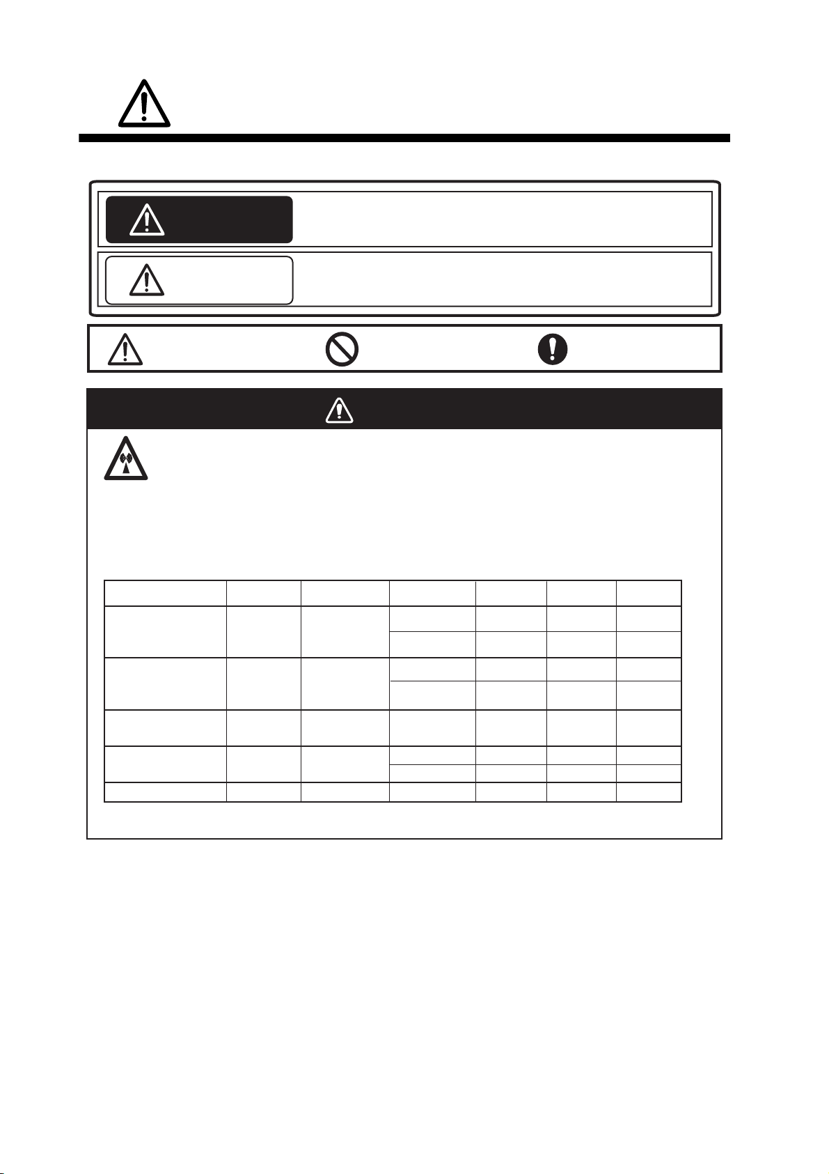
WARNING
Radio Frequency Radiation Hazard
The radar antenna emits electromagnetic radio frequency (RF) energy that can be harmful,
particularly to your eyes. Never look directly into the antenna aperture from a close distance
while the radar is in operation or expose yourself to the transmitting antenna at a close
distance. Distances at which RF radiation level of 100, 50 and 10 W/m
below.
Radar model
Transceiver Magnetron
Antenna*
100W/m
2
are given in the table
2
50W/m2
10W/m
2
FCR-2119(-BB)/
2819
FCR-2129(-BB)/
2829
FCR-2139S(-BB)/
2839S
FCR-2829W
FCR-2839SW
* XN20AF: 198cm, XN24AF: 243cm, SN36AF: 377cm
RTR-078A
RTR-079A MG5436
RTR-080
RTR-081A
RTR-082
MAF1565N
MG5223F
MG5436
MG5223F
XN20AF
XN24AF
XN20AF
XN24AF
SN36AF 0.1m 2.0m0.7m
XN20AF
XN24AF 0.2m 3.4m
SN36AF
0.1m
0.1m
0.5m
0.2m
0.4m
-
0.7m
0.4m
1.7m
1.0m
1.0m
0.5m
0.2m
2.2m
1.5m
4.6m
3.3m
5.6m
1.9m
ii
Page 5
SAFETY INSTRUCTIONS
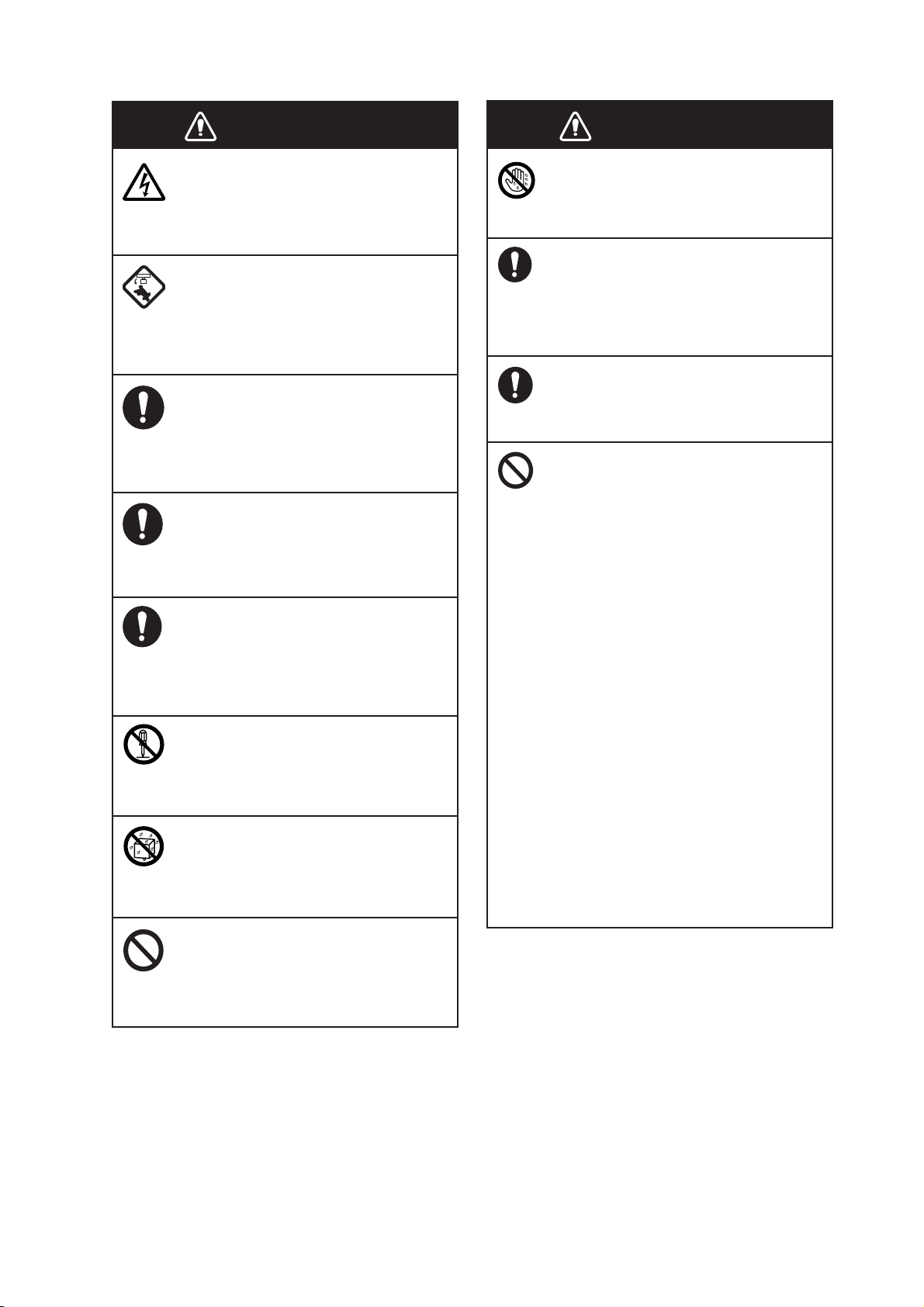
WARNING
Do not open the equipment.
The equipment uses high voltage that
can cause electrical shock. Refer any
repair work to a qualified technician.
Before turning on the radar, be sure
no one is near the antenna.
Prevent the potential risk of being
struck by the rotating antenna, which
can result in serious injury or death.
If water leaks into the equipment or
something is dropped into the
equipment, immediately turn off the
power at the switchboard.
Fire or electrical shock can result.
If the equipment is giving off smoke
or fire, immediately turn off the
power at the switchboard.
Fire or electrical shock can result.
If you feel the equipment is acting
abnormally or giving off strange
noises, immediately turn off the
power at the switchboard and
contact a FURUNO service technician.
Do not disassemble or modify the
equipment.
Fire, electrical shock or serious injury
can result.
Make sure no rain or water splash
leaks into the equipment.
Fire or electrical shock can result if
water leaks into the equipment.
WARNING
WARNING
Do not operate the equipment with
wet hands.
Electrical shock can result.
Keep objects away from the opentype antenna unit, so as not to
impede rotation of the antenna.
Fire, electrical shock or serious injury
can result.
Use the proper fuse.
Use of the wrong fuse can cause fire or
damage the equipment.
The TT function is a valuable aid to
navigation. However, the navigator
must check all aids available to
avoid collision.
- The TT automatically tracks an
automatically or manually acquired
radar target and calculates its course
and speed, indicating them with a
vector. Since the data generated by
the TT depends on the selected radar
targets, the radar must be optimally
tuned for use with the TT, to ensure
required targets will not be lost or
unnecessary targets, like sea returns
and noise, will not be acquired and
tracked.
- A target is not always a landmass,
reef, ship, but can also be returns
from the sea surface and from clutter.
As the level of clutter changes with
the environment, the operator must
correctly adjust the sea and rain
clutter controls and the gain control so
that the target echoes do not dis appear from the radar screen.
Do not place liquid-filled containers
on or near the equipment.
Fire or electrical shock can result if a
liquid spills into the equipment.
iii
Page 6
SAFETY INSTRUCTIONS
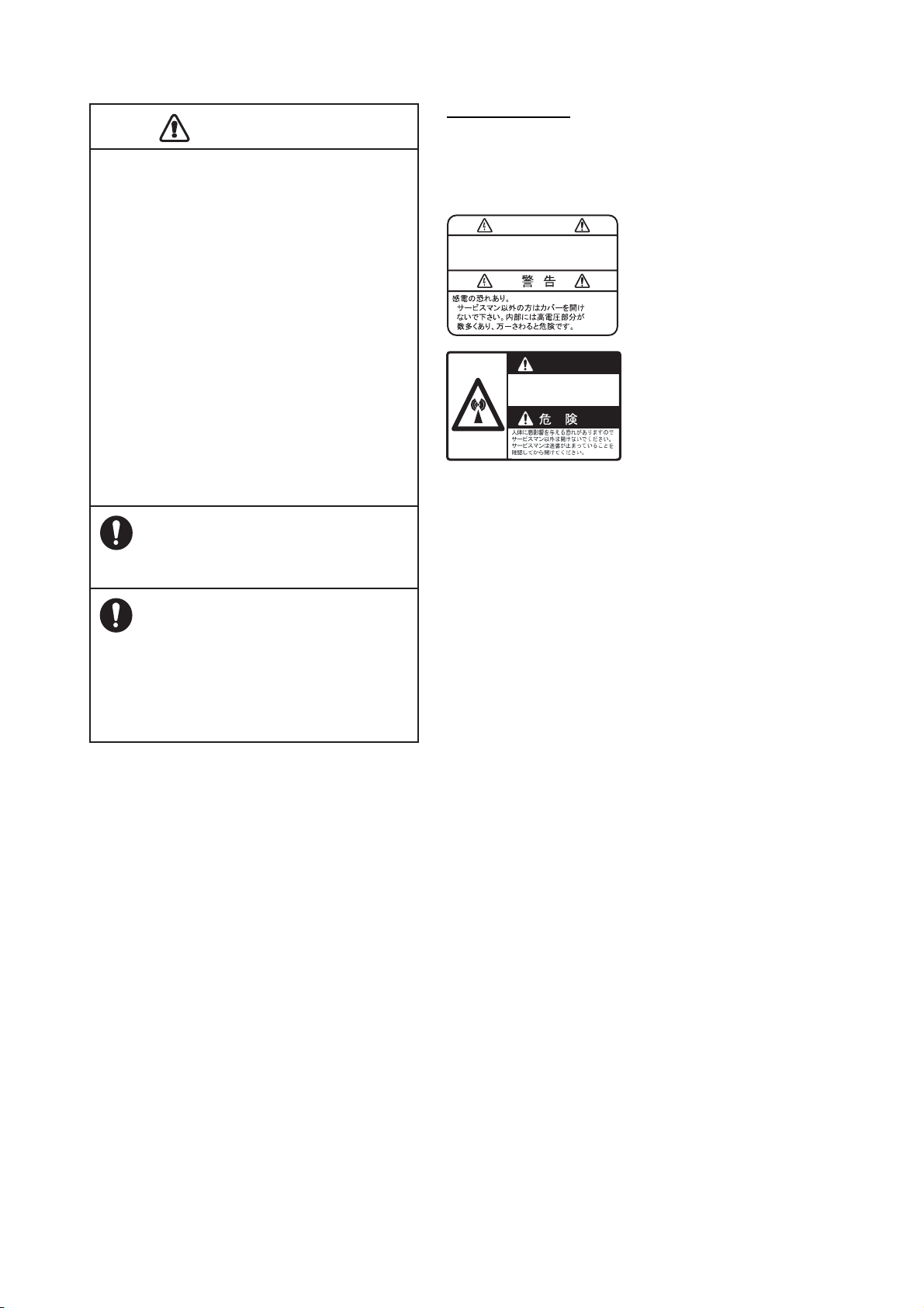
CAUTION
CAUTIO
The plotting accuracy and response of this
TT meets IMO standards. Tracking accuracy
is affected by the following:
•
Tracking accuracy is affected by course
change. One to two minutes is required to
restore vectors to full accuracy after an
abrupt course change. (The actual amount
depends on gyrocompass specifications.)
•
The amount of tracking delay is inversely
proportional to the relative speed of the
target. Delay is approx. 15-30 seconds for
the higher relative speed; approx. 30-60
seconds for the lower relative speed. The
following factors can affect accuracy:
- Echo intensity
- Radar transmission pulse length
- Radar bearing error
- Gyrocompass error
- Course change (own ship and targets)
Warning Label(s)
Warning label(s) is(are) attached to the
equipment. Do not remove the label(s). If a
label is missing or damaged, contact a
FURUNO agent or dealer about replacement.
WARNING
To avoid electrical shock, do not
remove cover. No user-serviceable
parts inside.
WARNING
Radiation hazard. Only qualified
personnel should work inside scanner.
Confirm that TX has stopped before
opening scanner.
Name: Warning Label 1
Type: 86-003-1011-1
Code No.: 100-236-231
Name: Warning Sticker
Type: 0
Code No.:
3-142-3201-0
100-266-890
Handle the LCD carefully.
The LCD is made of glass, which can
cause injury if broken.
The data presented by this equipment
is intended as a source of navigation
information.
The prudent navigator never relies
exclusively on any one source of
navigation information, for safety of
vessel and crew.
iv
Page 7

TABLE OF CONTENTS
FOREWORD................................................................................................................. xvi
SYSTEM CONFIGURATION ........................................................................................xix
1. OPERATIONAL OVERVIEW.................................................................................1-1
1.1 Units of the System ....................................................................................................1-1
1.1.1 Radar Control Unit RCU-025..........................................................................1-1
1.1.2 Trackball Control Unit RCU-026.....................................................................1-4
1.1.3 Processor Unit EC-3000.................................................................................1-5
1.2 How to Turn the System On/Off .................................................................................1-5
1.3 How to Adjust the Display Brilliance (FURUNO monitor) ...........................................1-6
1.3.1 Manual brilliance adjustment..........................................................................1-6
1.4 Operating Modes ........................................................................................................1-7
1.4.1 How to select an operating mode...................................................................1-7
1.4.2 Limitations when using the chart radar mode.................................................1-7
1.5 Display Screens..........................................................................................................1-8
1.5.1 Radar display .................................................................................................1-8
1.5.2 Chart radar display.......................................................................................1-10
1.5.3 Chart display ................................................................................................1-11
1.6 Status Bar.................................................................................................................1-12
1.6.1 Status bar for radar, chart radar mode.........................................................1-12
1.6.2 How to operate the buttons, slider bars on the Status bar ...........................1-13
1.7 InstantAccess Bar.....................................................................................................1-14
1.7.1 How to operate the buttons on the InstantAccess bar..................................1-16
1.8 Sensor Information, Datum Box ...............................................................................1-16
1.9 How to Select a Color Palette...................................................................................1-18
1.10 Menu Overview.........................................................................................................1-19
1.10.1 Basic menu operation...................................................................................1-19
1.10.2 How to enter numeric data ...........................................................................1-21
1.10.3 How to enter alphanumeric character data ..................................................1-21
1.11 Context-Sensitive Menus in the Radar Mode...........................................................1-22
1.11.1 Context-sensitive menus available with buttons and boxes .........................1-22
1.11.2 Context-sensitive menus in the display area in the radar and
chart radar modes ........................................................................................1-24
1.12 Cursor Position.........................................................................................................1-25
1.13 How to Select Sensor Settings.................................................................................1-25
1.14 How to Enter Ship Speed .........................................................................................1-26
1.15 How to Enter Heading ..............................................................................................1-28
1.16 How to Mark MOB Position ......................................................................................1-29
1.17 How to Offset Position..............................................................................................1-29
1.18 How to Select Time Format, Set Local Time............................................................1-30
1.19 How to Take a Screenshot of the Display ................................................................1-30
1.20 The Settings Menu ...................................................................................................1-31
1.21 User Profiles for Radar, Chart Radar .......................................................................1-31
1.21.1 How to create a profile .................................................................................1-31
1.21.2 How to disable a profile ................................................................................1-31
1.21.3 How to restore default settings to a profile ...................................................1-31
1.21.4 How to activate a profile ...............................................................................1-31
1.22 How to View Chart Software Version No., Chart System Information, and
Operator's Manual ....................................................................................................1-32
1.23 Tips (operational guidance) .....................................................................................1-32
v
Page 8

TABLE OF CONTENTS
2. RADAR, CHART RADAR OPERATION ...............................................................2-1
2.1 How to Transmit .........................................................................................................2-1
2.2 How to Tune the Radar Receiver...............................................................................2-1
2.2.1 How to initialize tuning ...................................................................................2-1
2.2.2 Automatic tuning ............................................................................................2-1
2.2.3 Manual tuning.................................................................................................2-1
2.3 Presentation Modes ...................................................................................................2-2
2.3.1 How to select a presentation mode................................................................2-2
2.3.2 Description of presentation modes................................................................. 2-3
2.4 How to Select the Range Scale .................................................................................2-6
2.5 Pulse Length ..............................................................................................................2-6
2.5.1 How to select a pulse length..........................................................................2-7
2.5.2 How to change the pulse length.....................................................................2-7
2.6 How to Adjust the Sensitivity ......................................................................................2-7
2.7 How to Suppress Sea Clutter.....................................................................................2-8
2.7.1 How to reduce sea clutter automatically ........................................................2-8
2.7.2 How to reduce sea clutter manually...............................................................2-8
2.8 How to Suppress Rain Clutter.................................................................................... 2-9
2.8.1 How to reduce rain clutter automatically ........................................................ 2-9
2.8.2 How to reduce rain clutter manually.............................................................2-10
2.9 How to Measure the Range to a Target ...................................................................2-11
2.9.1 How to measure the range by using a VRM ................................................2-11
2.9.2 How to set VRM attributes ...........................................................................2-12
2.10 How to Measure the Bearing to a Target .................................................................2-13
2.10.1 How to measure the bearing........................................................................ 2-13
2.10.2 How to select bearing reference ..................................................................2-14
2.11 Collision Assessment by Offset EBL........................................................................2-14
2.11.1 How to assess risk of collision ....................................................................2-14
2.11.2 Point of reference for origin point of offset EBL ........................................... 2-15
2.12 How to Measure the Range and Bearing Between Two Targets............................. 2-16
2.13 How to Off-center the Display ..................................................................................2-17
2.14 Interference Rejector................................................................................................2-18
2.15 Echo Stretch.............................................................................................................2-18
2.16 Echo Averaging........................................................................................................ 2-19
2.17 Noise Rejector..........................................................................................................2-20
2.18 Wiper........................................................................................................................ 2-21
2.19 Target Trails.............................................................................................................2-21
2.19.1 Target trails-related indications.................................................................... 2-21
2.19.2 True or relative target trails ..........................................................................2-22
2.19.3 Trail time ......................................................................................................2-22
2.19.4 How to reset target trails ..............................................................................2-22
2.19.5 How to temporarily remove all target trails from the display ........................ 2-23
2.19.6 Trail stabilization in true motion....................................................................2-23
2.19.7 Target trail attributes on the TRAIL menu.................................................... 2-23
2.20 Parallel Index (PI) Lines ...........................................................................................2-24
2.20.1 How to display, erase a PI line..................................................................... 2-24
2.20.2 How to adjust PI line orientation, PI line interval.......................................... 2-24
2.20.3 PI line attributes on the PI LINE menu......................................................... 2-25
2.20.4 How to reset PI lines ....................................................................................2-25
2.21 Zoom........................................................................................................................2-26
2.22 Markers ....................................................................................................................2-26
2.22.1 Heading line .................................................................................................2-26
2.22.2 Stern marker ................................................................................................2-26
2.22.3 North marker ................................................................................................2-27
2.22.4 Own ship marker.......................................................................................... 2-27
2.22.5 Vectors......................................................................................................... 2-27
vi
Page 9

TABLE OF CONTENTS
2.22.6 Barge marker................................................................................................2-28
2.22.7 Antenna marker............................................................................................2-28
2.22.8 Cursor...........................................................................................................2-29
2.23 How to Preset Controls for Specific Navigation Purpose .........................................2-29
2.23.1 How to select a picture preset ......................................................................2-31
2.23.2 User-programmable picture presets.............................................................2-31
2.23.3 How to restore user picture preset ...............................................................2-32
2.23.4 How to restore default picture preset options...............................................2-32
2.24 How to Suppress Second-trace Echoes...................................................................2-33
2.25 How to Adjust Brilliance of Screen Data...................................................................2-34
2.26 Watch Alert...............................................................................................................2-35
2.27 Information Box ........................................................................................................2-36
2.27.1 Information box contents ..............................................................................2-36
2.27.2 How to show the information box .................................................................2-37
2.27.3 How to turn NAV data on/off.........................................................................2-38
2.28 Interswitch ................................................................................................................2-39
2.28.1 Displaying antenna information ....................................................................2-39
2.28.2 How to preset antenna and display combinations........................................2-40
2.28.3 How to select an antenna.............................................................................2-42
2.29 Performance Monitor................................................................................................2-42
2.30 CCRP (Common Consistent Reference Point).........................................................2-44
2.31 Drop Mark.................................................................................................................2-46
2.31.1 How to show, hide the drop mark.................................................................2-46
2.31.2 How to inscribe a drop mark.........................................................................2-46
2.31.3 Drop mark bearing reference .......................................................................2-47
2.31.4 How to erase a drop mark ............................................................................2-47
2.32 Anchor Watch...........................................................................................................2-47
2.33 SART........................................................................................................................2-48
2.33.1 What is an SART?........................................................................................2-48
2.33.2 How to receive an SART ..............................................................................2-48
2.34 Alert Box, Alert List...................................................................................................2-50
2.34.1 Alert box .......................................................................................................2-50
2.34.2 Alert list.........................................................................................................2-50
2.34.3 Changing priority of primary alerts ...............................................................2-51
2.35 Echo Area.................................................................................................................2-51
2.36 Echo Color................................................................................................................2-52
2.37 Chart Radar Functions .............................................................................................2-52
2.37.1 How to switch between radar and chart radar modes ..................................2-52
2.37.2 How to show or hide chart objects ...............................................................2-53
2.37.3 How to create and recall custom sets of chart display objects.....................2-55
2.37.4 Chart database information ..........................................................................2-55
2.37.5 Chart scale indications .................................................................................2-56
2.37.6 Chart status ..................................................................................................2-56
2.37.7 Chart alert function .......................................................................................2-56
2.37.8 Notes details.................................................................................................2-57
2.38 Radar Observation ...................................................................................................2-58
2.38.1 General.........................................................................................................2-58
2.38.2 False echoes ................................................................................................2-60
2.38.3 RACON ........................................................................................................2-62
2.38.4 Radar Target Enhancer (RTE) .....................................................................2-62
3. TARGET TRACKING (TT)..................................................................................... 3-1
3.1 About TT.....................................................................................................................3-1
3.2 How to Show, Hide the TT Display.............................................................................3-1
3.3 How to Input Your Ship's Speed.................................................................................3-2
3.3.1 Echo-referenced speed input .........................................................................3-2
vii
Page 10

TABLE OF CONTENTS
3.4 Automatic Acquisition.................................................................................................3-3
3.4.1 How to enable auto acquisition...................................................................... 3-3
3.4.2 How to set an automatic acquisition zone...................................................... 3-4
3.5 Manual Acquisition .....................................................................................................3-5
3.5.1 How to set manual acquisition conditions ...................................................... 3-5
3.5.2 How to manually acquire a target................................................................... 3-5
3.6 How to Terminate Tracking of Targets (including reference targets) .........................3-6
3.6.1 How to cancel tracking on individual tracked targets..................................... 3-6
3.6.2 How to cancel tracking on all TTs ..................................................................3-6
3.7 TT Symbols and TT Symbol Attributes ......................................................................3-7
3.7.1 TT symbols.....................................................................................................3-7
3.7.2 TT symbol brilliance ....................................................................................... 3-8
3.7.3 Color for TT symbol........................................................................................ 3-8
3.8 How to Display TT Data .............................................................................................3-9
3.8.1 How to display target data for individual TT...................................................3-9
3.8.2 TT pop-up information..................................................................................3-10
3.8.3 Target list .....................................................................................................3-10
3.9 Vector Modes ...........................................................................................................3-11
3.9.1 Description of vectors................................................................................... 3-11
3.9.2 Vector motion and length............................................................................. 3-12
3.10 Past Position Display ...............................................................................................3-13
3.10.1 How to enable/disable the past position display, select past
position reference.........................................................................................3-13
3.10.2 Past position points...................................................................................... 3-13
3.11 How to Enter Set and Drift .......................................................................................3-14
3.12 TT CPA/TCPA Alarm ...............................................................................................3-15
3.12.1 How to set the CPA and TCPA limits........................................................... 3-15
3.12.2 How to enable, disable the TT CPA/TCPA alarm ........................................ 3-15
3.12.3 How to acknowledge the TT CPA/TCPA alarm............................................3-15
3.13 TT Lost Target Alarm ...............................................................................................3-16
3.13.1 How to enable, disable the TT lost target alarm...........................................3-16
3.13.2 How to set the TT lost target filter ................................................................3-16
3.14 Trial Maneuver .........................................................................................................3-17
3.14.1 Types of trial maneuvers.............................................................................. 3-17
3.14.2 How to do a trial maneuver ..........................................................................3-18
3.15 TT Performance Test ...............................................................................................3-20
3.16 TT Alerts...................................................................................................................3-21
3.17 Criteria for Selecting Targets for Tracking ...............................................................3-22
3.18 Factors Affecting Target Tracking............................................................................ 3-23
4. AIS OPERATION ...................................................................................................4-1
4.1 How to Deactivate the AIS Function ..........................................................................4-2
4.2 How to Show, Hide the AIS Display ...........................................................................4-3
4.3 AIS Symbols...............................................................................................................4-3
4.4 How to Filter AIS Targets ........................................................................................... 4-4
4.5 How to Activate Targets .............................................................................................4-5
4.5.1 How to activate specific target ....................................................................... 4-5
4.5.2 How to automatically activate targets.............................................................4-5
4.6 How to Sleep Targets.................................................................................................4-6
4.6.1 How to sleep an activated AIS target.............................................................4-6
4.6.2 How to sleep all activated AIS targets............................................................ 4-6
4.7 How to Display AIS Target Data ................................................................................4-7
4.7.1 AIS pop-up information ..................................................................................4-7
4.7.2 Basic AIS target data .....................................................................................4-7
4.7.3 Expanded AIS data ........................................................................................4-8
4.8 AIS CPA/TCPA Alarm ................................................................................................4-9
viii
Page 11

TABLE OF CONTENTS
4.9 AIS Symbol Brilliance .................................................................................................4-9
4.10 AIS Symbol Color .....................................................................................................4-10
4.11 AIS Lost Targets.......................................................................................................4-10
4.11.1 How to enable, disable the AIS lost target alarm .........................................4-10
4.11.2 How to set the AIS lost target filter ...............................................................4-11
4.12 How to Display AIS Target Past Positions................................................................4-11
4.12.1 How to enable/disable the past position display, select past
position reference.........................................................................................4-11
4.12.2 Past position points ......................................................................................4-12
4.13 How to Display True or Relative Speed Vectors ......................................................4-12
4.14 Association of TT and AIS Targets...........................................................................4-12
4.14.1 How to select association method................................................................4-12
4.14.2 How to set the conditions for association .....................................................4-13
4.15 Voyage Data.............................................................................................................4-14
4.16 AIS Messages ..........................................................................................................4-15
4.16.1 How to create and transmit a new AIS message .........................................4-15
4.16.2 How to transmit a saved AIS message ........................................................4-16
4.16.3 How to display received AIS messages .......................................................4-16
4.17 Other AIS Features...................................................................................................4-18
5. RADAR MAP AND TRACK ...................................................................................5-1
5.1 What is a Radar Map?................................................................................................5-1
5.2 Presentation Modes....................................................................................................5-1
5.3 How to Show, Hide the Radar Map Display ...............................................................5-1
5.4 How to Enter Radar Map Marks and Lines.................................................................5-2
5.5 How to Find Number of Map Points Used ..................................................................5-3
5.6 How to Select the Radar Map to Display....................................................................5-4
5.7 How to Attach a Comment to a Radar Map, Find Comment for a Map ......................5-4
5.8 How to Erase Radar Map Marks and Lines................................................................5-5
5.8.1 How to erase individual radar map marks and lines.......................................5-5
5.8.2 How to erase map marks and lines in an area...............................................5-5
5.8.3 How to erase all radar map marks and lines in a map file..............................5-6
5.9 How to Copy Radar Map Marks and Lines.................................................................5-7
5.9.1 How to copy individual radar map marks and lines to another map file .........5-7
5.9.2 How to copy radar map marks and lines within an area to another map file..5-7
5.9.3 How to copy all radar map marks and lines in a map file to another map file 5-8
5.10 How to Show, Hide Radar Map Features...................................................................5-8
5.11 Track...........................................................................................................................5-9
5.11.1 How to set up ship's track...............................................................................5-9
5.11.2 How to erase track .......................................................................................5-10
5.12 Route Display ...........................................................................................................5-10
5.13 User Chart Display ...................................................................................................5-11
6. CHART OVERVIEW ..............................................................................................6-1
6.1 Chart Screen Overview ..............................................................................................6-1
6.1.1 Electronic chart area ......................................................................................6-2
6.1.2 Status bar.......................................................................................................6-3
6.1.3 InstantAccess bar...........................................................................................6-5
6.1.4 Sensor information box ..................................................................................6-8
6.1.5 Own ship functions box ..................................................................................6-8
6.1.6 Route information box ....................................................................................6-9
6.1.7 Overlay/NAV Tools box ................................................................................6-10
6.1.8 Alert box .......................................................................................................6-10
6.1.9 Permanent warning box ...............................................................................6-10
6.1.10 EBL, VRM boxes ..........................................................................................6-11
6.1.11 Context-sensitive menus ..............................................................................6-11
ix
Page 12

TABLE OF CONTENTS
6.1.12 How to enter alphanumeric data ..................................................................6-12
6.2 How to Select the Operating Mode ..........................................................................6-13
6.3 How to Select the Chart Operating Mode ................................................................6-13
6.4 How to Select the Chart Scale .................................................................................6-14
6.5 How to Select the Presentation Mode......................................................................6-14
6.6 Cursor Position Box .................................................................................................6-15
6.7 The Standby Mode................................................................................................... 6-15
6.8 True Motion Reset....................................................................................................6-16
6.9 How to Control Route and User Charts in Voyage Navigation and
Voyage Planning Modes ..........................................................................................6-17
6.10 How to Use the VRM and EBL.................................................................................6-18
6.10.1 How to hide/show an EBL, VRM.................................................................. 6-18
6.10.2 How to measure the range and bearing....................................................... 6-18
6.10.3 How to select bearing reference ..................................................................6-18
6.10.4 EBL, VRM functions available with the context-sensitive menu...................6-19
6.11 Split Screen..............................................................................................................6-20
6.12 Datum.......................................................................................................................6-21
6.12.1 General ........................................................................................................ 6-21
6.12.2 Paper charts................................................................................................. 6-21
6.12.3 Electronic sea charts....................................................................................6-21
6.12.4 Positioning devices and datum .................................................................... 6-21
6.12.5 Chart radar and datum................................................................................. 6-21
6.13 Set up Before Departure ..........................................................................................6-22
6.13.1 Updates before departure ............................................................................6-22
6.13.2 Create or update a route.............................................................................. 6-23
6.13.3 How to check and prepare route to monitor................................................. 6-24
6.13.4 Check configuration of navigation sensors .................................................. 6-26
6.13.5 How to reset odometer and trip meter..........................................................6-27
7. HOW TO MANAGE CHARTS ................................................................................7-1
7.1 How to Install Licenses ..............................................................................................7-1
7.1.1 Automatic installation of license..................................................................... 7-1
7.1.2 Manual installation of license ......................................................................... 7-3
7.1.3 How to backup, restore licenses ....................................................................7-3
7.1.4 How to display ENC permit ............................................................................ 7-3
7.1.5 How to export the ENC license list.................................................................7-3
7.2 How to Install Public Keys for S57 Charts..................................................................7-4
7.3 How to Install Charts from a CD-ROM, Other Media ................................................ 7-5
7.4 Manual Installation of S57 Charts that are not Fully Compliant with IMO Standards. 7-7
7.5 How to View Permit Status.........................................................................................7-8
7.6 How to Display Install/Update History ........................................................................7-9
7.7 Catalog of Chart Cells ..............................................................................................7-10
7.7.1 How to group chart cells............................................................................... 7-12
7.7.2 How to view status of chart cells..................................................................7-13
7.8 How to Open Charts.................................................................................................7-14
7.9 How to Delete Charts ...............................................................................................7-14
7.10 How to Show Publishers Notes for S57 Charts........................................................7-14
7.11 How to Export a List of Charts .................................................................................7-14
7.12 How to Find the Chart Type .....................................................................................7-15
7.13 How to Update Charts Manually ..............................................................................7-15
7.13.1 How to insert update symbols...................................................................... 7-16
7.13.2 How to delete update symbols..................................................................... 7-17
7.13.3 How to modify existing update symbols....................................................... 7-18
8. HOW TO CONTROL CHART OBJECTS..............................................................8-1
8.1 How to Browse Your Charts .......................................................................................8-1
x
Page 13

TABLE OF CONTENTS
8.2 How to Control Visibility of Chart Objects...................................................................8-1
8.2.1 How to set value for shallow contour, safety depth, safety contour and
deep contour ..................................................................................................8-1
8.2.2 Basic Setting menu ........................................................................................8-3
8.2.3 Chart Display menu........................................................................................8-4
8.2.4 Display base...................................................................................................8-5
8.3 How to Control Visibility of Symbols, Features...........................................................8-5
8.3.1 General page..................................................................................................8-5
8.3.2 Tracking page.................................................................................................8-7
8.3.3 Route page.....................................................................................................8-8
8.3.4 Mariner page ..................................................................................................8-8
8.3.5 Targets page ..................................................................................................8-9
8.4 Control of Predefined IMO Chart Display Settings ...................................................8-10
9. VECTOR (S57) CHARTS.......................................................................................9-1
9.1 Introduction to S57 Charts..........................................................................................9-1
9.1.1 Definitions of terms.........................................................................................9-2
9.1.2 Chart legend for S57 charts ...........................................................................9-2
9.1.3 Permanent warnings for S57 charts...............................................................9-3
9.2 Sailing Directions, Tidal Tables, etc., Features of S57 Charts ...................................9-4
9.3 Chart Viewing Dates and Seasonal Features of the S57 Chart .................................9-4
9.3.1 Introduction.....................................................................................................9-4
9.3.2 How to approve and highlight S57 chart updates...........................................9-4
9.3.3 How to set Display date and Approved until dates.........................................9-5
9.3.4 About chart viewing date dependency of S57 standard.................................9-5
9.4 Symbology Used in S57 Charts..................................................................................9-7
9.4.1 Presentation library used for S57 chart features............................................9-7
9.5 How to Find Information About S57 Chart Objects....................................................9-8
9.5.1 How to set visible S57 chart features .............................................................9-8
9.5.2 How to find information about a chart object ..................................................9-8
9.6 Admiralty Information Overlay (AIO)...........................................................................9-9
9.6.1 Installation ......................................................................................................9-9
9.6.2 How to display the AIO...................................................................................9-9
9.6.3 Catalog of AIO cells......................................................................................9-10
9.6.4 How to find AIO chart object information......................................................9-11
9.6.5 How to select the information to display.......................................................9-12
10. C-MAP CHARTS..................................................................................................10-1
10.1 C-MAP Cartographic Service ...................................................................................10-1
10.2 How to Register the System at C-MAP Norway .......................................................10-1
10.3 How to Order Charts.................................................................................................10-1
10.4 How to Apply for Licenses........................................................................................10-1
10.5 Troubleshooting........................................................................................................10-2
10.6 Chart Subscription Services .....................................................................................10-2
10.6.1 C-MAP services............................................................................................10-2
10.6.2 What is ENC delivery? .................................................................................10-2
10.7 Chart Display............................................................................................................10-3
10.7.1 Introduction...................................................................................................10-3
10.8 Permanent Warnings................................................................................................10-4
11. CHART ALERTS .................................................................................................11-1
11.1 Chart Alerts...............................................................................................................11-2
11.1.1 How to set safety contour.............................................................................11-2
11.1.2 How to select objects used in chart alerts ....................................................11-3
11.2 How to Activate Own Ship Check.............................................................................11-3
xi
Page 14

TABLE OF CONTENTS
11.3 Route Planning.........................................................................................................11-5
11.3.1 Chart alerts for route planning......................................................................11-5
11.4 Route Monitoring......................................................................................................11-6
12. ROUTES...............................................................................................................12-1
12.1 Route Planning Overview.........................................................................................12-1
12.2 Main Menu for Route Planning.................................................................................12-2
12.3 How to Create a New Route ....................................................................................12-2
12.3.1 How to use the Waypoints page .................................................................. 12-4
12.3.2 How to use the User Chart page.................................................................. 12-5
12.3.3 How to use the Optimize page..................................................................... 12-5
12.3.4 How to use the Alert parameters page.........................................................12-6
12.3.5 How to use the Check results page ............................................................. 12-8
12.4 How to Import a Route Created with ECDIS FEA-2x07........................................... 12-8
12.5 How to Modify an Existing Route .............................................................................12-9
12.5.1 How to change waypoint position.................................................................12-9
12.5.2 How to change other waypoint data........................................................... 12-10
12.5.3 How to add a new waypoint at the end of a route...................................... 12-10
12.5.4 How insert a waypoint between waypoints ................................................ 12-10
12.5.5 How to delete a waypoint........................................................................... 12-10
12.5.6 Geometry check of route............................................................................ 12-11
12.6 SAR Operations .....................................................................................................12-11
12.7 Route Bank ............................................................................................................12-14
12.8 Route Optimization.................................................................................................12-15
12.8.1 Available route optimization strategies.......................................................12-15
12.8.2 How to optimize a route ............................................................................. 12-16
12.8.3 How to plan a speed profile........................................................................12-17
12.9 Reports...................................................................................................................12-18
12.10How to Delete Routes............................................................................................12-22
13. USER CHARTS....................................................................................................13-1
13.1 Introduction ..............................................................................................................13-1
13.1.1 Objects of user charts .................................................................................. 13-1
13.2 How to Create a User Chart.....................................................................................13-2
13.3 How to Import a User Chart Created with ECDIS FEA-2x07 ...................................13-6
13.4 How to Edit Objects on a User Chart .......................................................................13-7
13.4.1 How to edit objects on the chart area...........................................................13-7
13.4.2 How to edit objects from the User Chart dialog box..................................... 13-7
13.5 How to Delete Objects from a User Chart................................................................13-8
13.6 How to Select the User Chart Objects to Display.....................................................13-8
13.7 How to Delete User Charts ......................................................................................13-9
13.8 User Chart Reports ..................................................................................................13-9
14. HOW TO MONITOR ROUTES.............................................................................14-1
14.1 How to Select the Route to Monitor .........................................................................14-1
14.2 How to Stop Monitoring a Route ..............................................................................14-3
14.3 How to Select What Parts of a Route to Display...................................................... 14-3
14.4 How to View Waypoint Information ..........................................................................14-4
14.5 How to View User Chart Information........................................................................14-5
14.6 How to Monitor a Route ...........................................................................................14-5
14.7 How to Change Monitored Route to Planned Route................................................ 14-6
15. NAV TOOLS.........................................................................................................15-1
15.1 How to Access the Nav Tools ..................................................................................15-1
15.2 Parallel Index (PI) Lines ...........................................................................................15-2
15.2.1 How to activate, deactivate PI lines ............................................................. 15-2
xii
Page 15

TABLE OF CONTENTS
15.2.2 PI line bearing reference ..............................................................................15-2
15.2.3 Number of PI lines to display........................................................................15-2
15.2.4 PI line mode .................................................................................................15-2
15.2.5 How to adjust PI line orientation, PI line interval ..........................................15-3
15.2.6 How to reset the PI lines ..............................................................................15-3
15.3 Check Area...............................................................................................................15-4
15.4 Ring ..........................................................................................................................15-4
15.5 Predictor ...................................................................................................................15-5
15.6 Anchor Watch...........................................................................................................15-6
15.7 UKC (Under Keel Clearance) ...................................................................................15-7
15.7.1 UKC overview...............................................................................................15-7
15.7.2 How to set UKC............................................................................................15-7
15.7.3 UKC window.................................................................................................15-8
16. NAVIGATION SENSORS ....................................................................................16-1
16.1 CCRS .......................................................................................................................16-1
16.2 How to Select Navigation Sensors ...........................................................................16-2
16.2.1 Sensors menu description............................................................................16-2
16.3 Source of Position ....................................................................................................16-6
16.4 Primary and Secondary Positions of Own Ship........................................................16-7
16.5 Source of Navigation Data........................................................................................16-8
16.6 Switching of Sensor and Resulting Indication ........................................................16-10
16.7 Filter Status ............................................................................................................16-10
16.8 Position Alignment..................................................................................................16-12
16.8.1 How to align position ..................................................................................16-12
16.8.2 How to cancel position alignment...............................................................16-12
16.9 Wind Sensor...........................................................................................................16-13
16.10Depth Sensor.........................................................................................................16-14
17. AIS SAFETY, NAVTEX MESSAGES .................................................................. 17-1
17.1 AIS Safety Messages ...............................................................................................17-1
17.1.1 How to send an AIS safety message ...........................................................17-1
17.1.2 How to manage received and sent AIS safety messages ............................17-2
17.2 Navtex Messages.....................................................................................................17-3
17.2.1 How to receive Navtex messages ................................................................17-3
17.2.2 How to manage received Navtex messages ................................................17-4
18. TT AND AIS DISPLAYS ......................................................................................18-1
18.1 TT Display ................................................................................................................18-1
18.1.1 TT symbols...................................................................................................18-1
18.1.2 TT symbol color and size .............................................................................18-2
18.1.3 How to display tracked target data ...............................................................18-3
18.1.4 Past position point attributes ........................................................................18-4
18.1.5 How to set the TT lost target alarm filter ......................................................18-5
18.1.6 TT recording functions..................................................................................18-5
18.2 AIS Display...............................................................................................................18-6
18.2.1 AIS symbols .................................................................................................18-6
18.2.2 Voyage data .................................................................................................18-7
18.2.3 How to filter AIS targets................................................................................18-8
18.2.4 How to set conditions for automatic activation of sleeping targets...............18-9
18.2.5 How to sleep all activated targets.................................................................18-9
18.2.6 How to set the AIS lost target alarm filter ...................................................18-10
18.2.7 How to display AIS target data ...................................................................18-10
18.2.8 How to display own ship data.....................................................................18-12
xiii
Page 16

TABLE OF CONTENTS
19. RECORDING FUNCTIONS..................................................................................19-1
19.1 How to Record User, Position Events......................................................................19-1
19.1.1 User events.................................................................................................. 19-1
19.1.2 Position events............................................................................................. 19-2
19.2 Details Log ...............................................................................................................19-3
19.3 Voyage Log.............................................................................................................. 19-4
19.3.1 How to set conditions of logging .................................................................. 19-5
19.4 Chart Usage Log ......................................................................................................19-6
19.5 Danger Targets Log .................................................................................................19-7
19.5.1 How to set the conditions for logging danger targets................................... 19-8
20. ALERTS ...............................................................................................................20-1
20.1 Alerts, Alert System..................................................................................................20-1
20.1.1 Alert box description.....................................................................................20-1
20.1.2 Alert messages ............................................................................................20-1
20.1.3 Alert state icons............................................................................................20-4
20.1.4 Buzzer stop icon...........................................................................................20-4
20.2 Alert List ................................................................................................................... 20-5
20.3 Alert Log................................................................................................................... 20-7
20.4 Alert Reception from Connected Sensors................................................................ 20-7
20.5 List of Alerts .............................................................................................................20-8
21. PARAMETERS.....................................................................................................21-1
21.1 Ship and Route Parameters.....................................................................................21-1
21.2 Cost Parameters ......................................................................................................21-2
22. MINI CONNING DISPLAY....................................................................................22-1
23. SETTINGS MENU ................................................................................................23-1
23.1 How to Access the Settings Menu ...........................................................................23-1
23.2 File Export ................................................................................................................23-2
23.3 File Import ................................................................................................................23-3
23.4 Self Test ................................................................................................................... 23-4
23.5 Data Sharing ............................................................................................................23-5
23.6 Customize ................................................................................................................23-6
23.7 Display Test .............................................................................................................23-7
23.8 Keyboard Test..........................................................................................................23-8
23.9 Screenshots ...........................................................................................................23-10
23.9.1 How to export screenshots.........................................................................23-11
23.9.2 How to delete screenshots......................................................................... 23-11
23.10User Default...........................................................................................................23-12
23.11CCRP .................................................................................................................... 23-13
24. COMMON REFERENCE SYSTEM ......................................................................24-1
24.1 Installation of the System......................................................................................... 24-1
24.2 Accuracy of the System ...........................................................................................24-1
25. MAINTENANCE AND TROUBLESHOOTING.....................................................25-1
25.1 Maintenance.............................................................................................................25-2
25.2 How to Replace the Fuses....................................................................................... 25-3
25.3 Trackball Maintenance............................................................................................. 25-4
25.4 How to Clean the Filter in the Processor Unit ..........................................................25-4
25.5 Troubleshooting .......................................................................................................25-5
25.6 Consumable Parts....................................................................................................25-7
25.7 Color Differentiation Test for S57 Charts .................................................................25-8
xiv
Page 17

TABLE OF CONTENTS
APPENDIX 1 MENU TREE .......................................................................................AP-1
APPENDIX 2 ABBREVIATIONS, SYMBOLS........................................................... AP-9
APPENDIX 3 DIGITAL INTERFACE ......................................................................AP-23
APPENDIX 4 DATA COLOR AND MEANING........................................................AP-33
SPECIFICATIONS .....................................................................................................SP-1
INDEX ......................................................................................................................... IN-1
Declaration of Conformity
xv
Page 18

FOREWORD
Congratulations on your choice of the FURUNO FCR-21x9(-BB), FCR-28x9 Series Marine Radar.
We are confident you will see why the FURUNO name has become synonymous with quality and
reliability.
Since 1948, FURUNO Electric Company has enjoyed an enviable reputation for innovative and
dependable marine electronics equipment. This dedication to excellence is furthered by our extensive global network of agents and dealers.
This equipment is designed and constructed to meet the rigorous demands of the marine environment. However, no machine can perform its intended function unless installed, operated and
maintained properly. Please carefully read and follow the recommended procedures for operation
and maintenance.
Features
This radar series meets the requirements of IEC 62388 (Marine navigation and radiocommunication equipment and systems - Shipborne radar - Performance requirements, method of testing and
required test results) and IMO MSC.192(79), IMO Resolution A.817(19), and IEC 61174. This radar displays radar targets, electronic charts, nav lines, Tracked Target (TT) data, AIS targets and
other navigation data on a 23.1-inch display (FCR-28x9).
The main features of this series are
• The FCR-21x9
Model
FCR-2119(-BB) X-band Local supply 12 kW Antenna unit
FCR-2129(-BB) 25 kW Antenna unit
FCR-2139S(-BB) 30 kW Antenna unit
FCR-2819 X-band 23.1”* 12 kW Antenna unit
FCR-2829 X-band 25 kW Antenna unit
FCR-2829W X-band 25 kW Transceiver unit
FCR-2839S S-band 30 kW Antenna unit
FCR-2839SW Transceiver unit
* Viewing distance: 1020 mm
• New HMI (Human Machine Interface) gives improved operability.
• Accepts SXGA, UXGA video inputs.
• SOLAS category 2 compatible display (320 mm). (Category 1 compatible display optionally available.)
• Radar, chart and chart radar modes. (The chart radar mode does not meet the criteria for navigation aid for Japanese flag vessels as defined by Japanese law.)
• Many warning features to support safer and more efficient navigation.
• Grounding warnings, safe depth contours.
• Chart database loaded and updated using CD-ROMs.
• Tracked Target (TT) data and AIS data to aid in collision avoidance.
• AIS messaging.
• Route created in chart mode can be displayed on the radar.
• Route planning and route monitoring facilities in the chart mode.
(-BB), FCR-28x9 series consists of the following models and configurations:
Frequency
Band
Size of
Monitor Unit
Output
Power
Transceiver
location
xvi
Page 19

FOREWORD
Signal Processing Functions
This radar has the signal processing functions described in the table below. All signal processing
functions are set with the picture preset feature.
Signal processing function Description Section
Interference rejector Suppress interference transmitted by other radars. Inter-
ference received simultaneously from many radars can
be difficult to reduce.
Echo stretch Enlarge target echoes, especially small echoes. Sup-
press interference, sea clutter and rain clutter before using echo stretch, to prevent the enlargement of unwanted
echoes.
Echo averaging The radar samples echoes with each scan. Targets that
show a large change with each scan are judged as clutter
and are reduced to display only echoes from legitimate
targets.
Noise rejector Suppress white noise and increase the S/N ratio to im-
prove picture clarity.
2.14
2.15
2.16
2.17
Standards Used in this Manual
• Three types of Control Units are available: Radar Control Unit RCU-025 (radar controls with
trackball module), ECDIS Control Unit RCU-024 (alphabet keyboard, controls, trackball module) and Trackball Control Unit RCU-026 (trackball module only). Unless noted otherwise, “Control Unit” refers to the RCU-025.
• The system can be operated with the controls of the Radar Control Unit, ECDIS Control Unit or
a trackball module. The descriptions in this manual use the trackball module.
• Unless noted otherwise, "click" means to push the left button on a trackball module.
• The keys and controls of the Radar Control Unit are shown in bold face; for example, the EN-
TER key.
• The buttons on the InstantAccess bar, Status bar and menu items are shown in brackets; for
example, the [TUNE] button.
• Context-sensitive menus are available with many buttons, and boxes and objects. Right-click
an item to display the related context-sensitive menu.
• This radar is available in three types of specifications: IMO, A, or B. This manual provides the
descriptions for the B type, of which some functions are not available with the IMO or A type.
See the menu tree in Appendix 1 for function availability.
• “C-MAP” means “C-MAP by Jeppesen”.
xvii
Page 20

FOREWORD
Program Number
System Program no. Version no.
Radar
SPU 0359204 03
RFC 0359202 01
EC-3000
Main 0359266 01
Virus Prevention
The ECDIS is not equipped with a virus checker. The ECDIS operates in real time; therefore, having a virus checker that periodically checks the equipment for viruses would increase the processing load, which can affect operation. However, you can avoid viruses by following the instructions
in this section.
When you update a chart
The PC and medium (USB flash memory, etc.) used to download and store an update for an existing chart or a new chart may be infected with a virus. Check the PC and the medium for viruses
with a commercial virus checker - BEFORE you connect them to the ECDIS. Be sure the virus
checker contains the latest virus definition files.
Network connection
The ECDIS receives and displays information from various navigation equipment and radar via a
LAN. A PC and other equipment connected to a network can carry viruses. To prevent the introduction of a virus to the LAN, DO NOT connect the ECDIS or HUB to an external network, including other shipboard LAN.
Do not install 3rd party programs in the ECDIS
Programs installed via an external network can carry viruses that can cause the ECDIS to mal-
®
function. Do not install any Windows
software.
Open Source Software
This product includes software to be licensed under the GNU General Public License (GPL), GNU
Lesser General Public License (LGPL), BSD, Apache, MIT and others. The program(s) is/are free
software(s), and you can copy it and/or redistribute it and/or modify it under the terms of the GPL
or LGPL as published by the Free Software Foundation. Please access to the following URL if you
need source codes: https://www.furuno.co.jp/cgi/cnt_oss_e01.cgi
This product uses the software module that was developed by the Independent JPEG Group.
Reverse engineering
Reverse engineering (reverse assemble, reverse compiler) of the software of this equipment is
prohibited.
xviii
Page 21
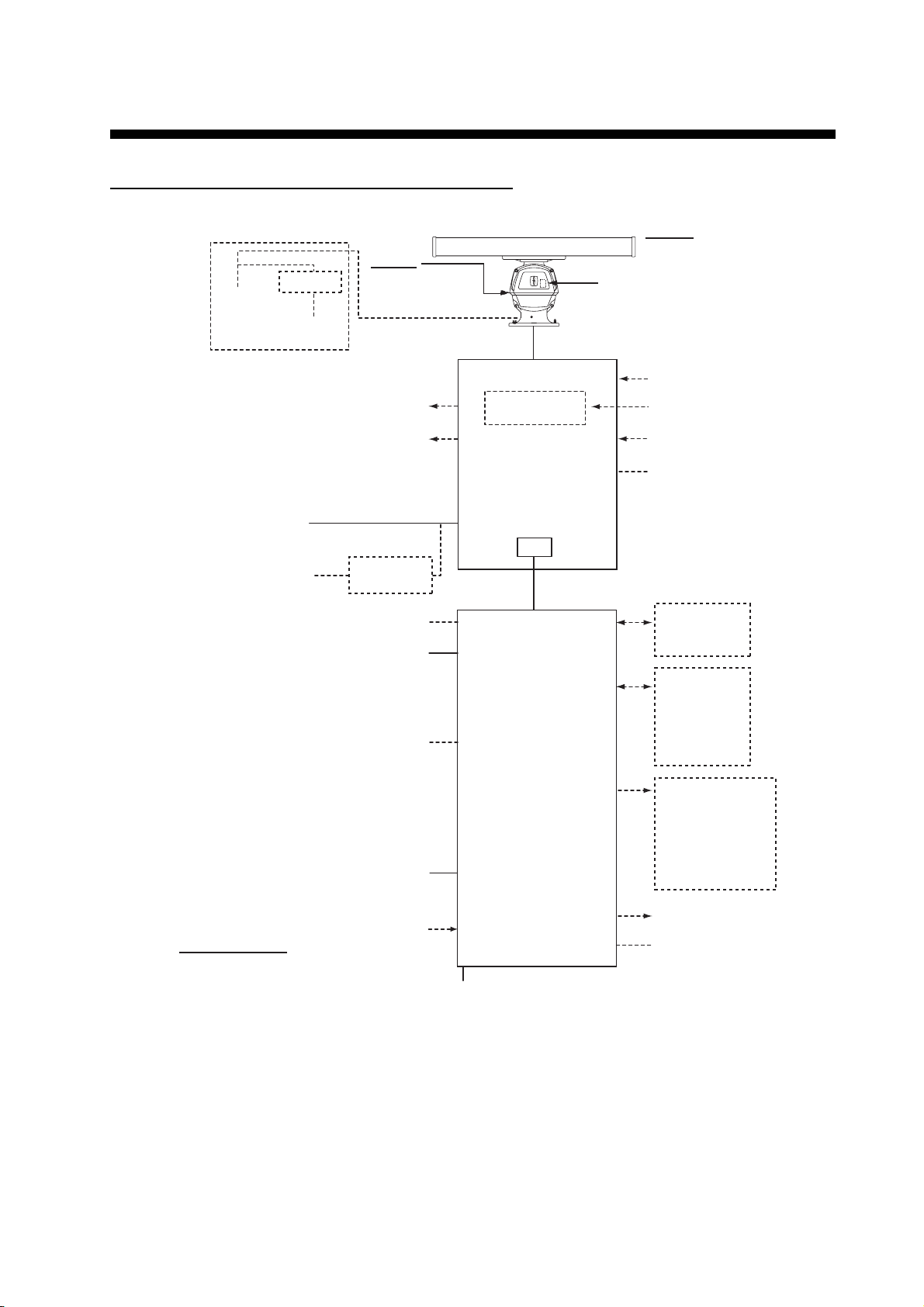
SYSTEM CONFIGURATION
FCR-2119(-BB)/2129(-BB)/2139S(-BB)/2819/2829
DE-ICER
110 VAC
1ø, 50/60 Hz
RU-3305
ANTENNA UNIT
Chassis
RSB-096-078A
RSB-097-078A
RSB-096-079A
RSB-097-079A
Radiator
XN-20AF (6 ft)
XN-24AF (8 ft)
Performance Monitor
PM-31
110/115/220/230 VAC
1ø, 50/60 Hz
A-D Converter
Sub Display 1
Sub Display 2
Gyro Converter
GC-10
RPU-013
RADAR
Gyrocompass
Heading Sensor
Brake Unit
BR-001/002
PROCESSOR
110-115/
220-230 VAC
1ø, 50/60 Hz
440 VAC
1ø, 50/60 Hz
Sensor Adapter
Radar Control
Unit RCU-025
Trackball Control Unit
ECDIS Control Unit
Radar Control
Unit RCU-025
Trackball Control Unit
Transformer
RU-1803
*2
OR
RCU-026
RCU-024
OR
OR
RCU-026
UNIT
LAN
EC-3000
PROCESSOR
UNIT
Serial 1, 2
IEC-61162-2
(Gyro, AIS)
Serial 3 - 8
IEC-61162-1
(GPS, Log,
Echo sounder,
Wind, Alarm,
Navtex, etc.)
Digital Out 1 - 6
1: System Fail
2: Power Fail
3: Normal Close 1
4: Normal Close 2
5: Normal Open 1
Monitor Unit
*1
6: Normal Open 2
FCR-21x9-BB series: MU-190 (option)
FCR-28x9 series: MU-231
VDR
Digital In (ACK IN)
Category of Units
Antenna Unit: Exposed to the weather
All other units: Protected from the weather
100-115/220-230 VAC
1ø, 50/60 Hz
EPFS must meet MSC.112(73); SMDE must meet MSC.96(72). GPS speed data does not meet IMO
requirements unless type approved for compliance with IMO resolution MSC.96(72). The update rate of
the gyrocompass must be better than 40 Hz (HSC) or 20 Hz (other than HSC).
*1
These monitors have been approved by the IMO, MU-190 for CAT 2C and CAT 2HC, MU-231
for CAT 1C and CAT 1HC. If a different monitor is to be used on IMO vessels, its effective
diameter must meet the applicable Category requirements:
CAT 1C and CAT 1HC: effective diameter 320 mm or higher
CAT 2C and CAT 2HC: effective diameter 250 mm or higher
For installation, operation and viewing distance of other monitor, see its manuals.
*2
Control Serial MC-3010S, Analog IN MC-3010A, Digital IN MC-3020D, Digital OUT MC-3030D
Intelligent Hub
HUB-3000
Dashed lines indicate
optional or local supply
equipment.
xix
Page 22
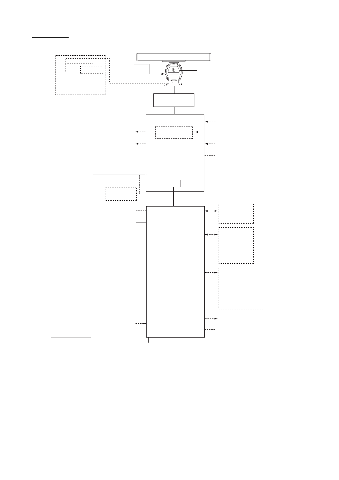
SYSTEM CONFIGURATION
FCR-2829W
DE-ICER
110 VAC
RU-3305
1ø, 50/60 Hz
110/115/220/230 VAC
1ø, 50/60 Hz
110-115/
220-230 VAC
1ø, 50/60 Hz
440 VAC
1ø, 50/60 Hz
Sensor Adapter
Trackball Control Unit
ECDIS Control Unit
Trackball Control Unit
Chassis
RSB-103
Sub Display 1
Sub Display 2
Transformer
RU-1803
Radar Control
Unit RCU-025
OR
RCU-026
RCU-024
OR
Radar Control
Unit RCU-025
OR
RCU-026
Monitor Unit
MU-231
ANTENNA UNIT
Radiator
XN-20AF (6 ft)
XN-24AF (8 ft)
Performance Monitor
PM-31
Transceiver Unit
RTR-081A
A-D Converter
Gyro Converter
GC-10
Gyrocompass
Heading Sensor
RPU-013
RADAR
Brake Unit
BR-001/002
PROCESSOR
UNIT
LAN
*2
Serial 1, 2
IEC-61162-2
(Gyro, AIS)
Serial 3 - 8
IEC-61162-1
(GPS, Log,
Echo sounder,
Wind, Alarm,
Navtex, etc.)
EC-3000
PROCESSOR
UNIT
Digital Out 1 - 6
1: System Fail
2: Power Fail
3: Normal Close 1
4: Normal Close 2
5: Normal Open 1
6: Normal Open 2
*1
xx
Digital In (ACK IN)
VDR
Intelligent Hub
Category of Units
Antenna Unit: Exposed to the weather
All other units: Protected from the weather
EPFS must meet MSC.112(73); SMDE must meet MSC.96(72). GPS speed data does not meet IMO
requirements unless type approved for compliance with IMO resolution MSC.96(72). The update rate of the
gyrocompass must be better than 40 Hz (HSC) or 20 Hz (other than HSC).
*1
The MU-231 monitor meets the Category requirements for CAT 1C and CAT 1HC. If a different monitor
is to be used on IMO vessels, its effective diameter must meet the applicable Category requirements:
CAT 1C and CAT 1HC: effective diameter 320 mm or higher
CAT 2C and CAT 2HC: effective diameter 250 mm or higher
For installation, operation and viewing distance of other monitor, see its manuals
*2
Control Serial MC-3010S, Analog IN MC-3010A, Digital IN MC-3020D, Digital OUT MC-3030D
100-115/220-230 VAC,
1ø, 50/60 Hz
HUB-3000
Dashed lines indicate
optional or local supply
equipment.
Page 23
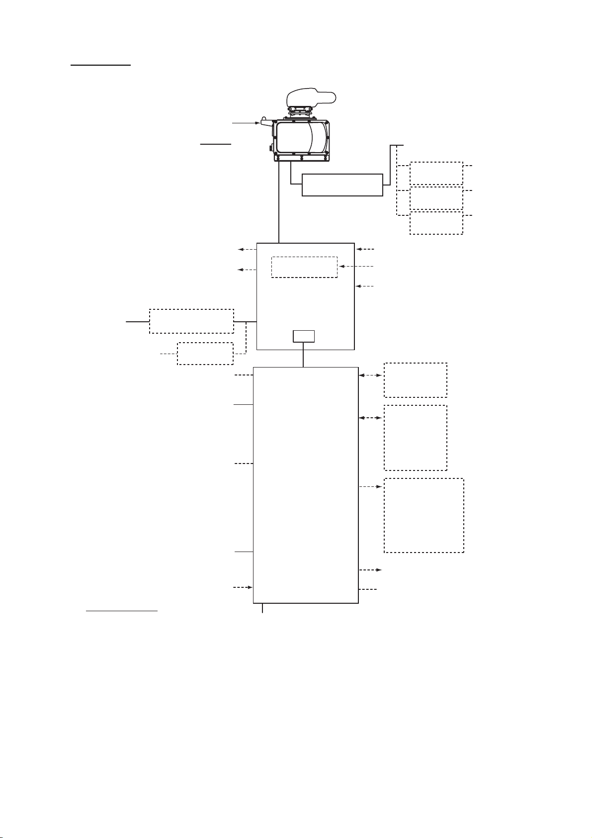
FCR-2839S
SYSTEM CONFIGURATION
ANTENNA UNIT
Performance Monitor
PM-51
Chassis
RSB-098/099
RSB-100/101/102
Sub Display 1
Sub Display 2
110-115/
220-230 VAC
Power Supply Unit
PSU-011
1ø, 50/60 Hz
440 VAC
1ø, 50/60 Hz
Transformer
RU-1803
Sensor Adapter
*2
Radar Control
Unit RCU-025
OR
Trackball Control Unit
RCU-026
ECDIS Control Unit
RCU-024
OR
Radar Control
Unit RCU-025
OR
Trackball Control Unit
RCU-026
Monitor Unit
MU-231
*1
Digital In (ACK IN)
Category of Units
Antenna Unit: Exposed to the weather
All other units: Protected from the weather
Radiator
SN36AF (12 ft)
Power Supply Unit
PSU-007
Gyro Converter
GC-10
RPU-013
RADAR
PROCESSOR
UNIT
LAN
EC-3000
PROCESSOR
UNIT
100-115/220-230 VAC
1ø, 50/60 Hz
200/380 VAC, 3ø, 50 Hz
220/440 VAC, 3ø, 60 Hz
Transformer
RU-5693
Transformer
RU-6522
Transformer
RU-5466
A-D Converter
Gyrocompass
Heading Sensor
Serial 1, 2
IEC-61162-2
(Gyro, AIS)
Serial 3 - 8
IEC-61162-1
(GPS, Log,
Echo sounder,
Wind, Alarm,
Navtex, etc.)
Digital Out 1 - 6
1: System Fail
2: Power Fail
3: Normal Close 1
4: Normal Close 2
5: Normal Open 1
6: Normal Open 2
VDR
Intelligent Hub
HUB-3000
Dashed lines indicate
optional or local supply
equipment.
110 VAC,
3ø, 60 Hz
220 VAC,
3ø, 50 Hz
440 VAC,
3ø, 50 Hz
EPFS must meet MSC.112(73); SMDE must meet MSC.96(72). GPS speed data does not meet IMO
requirements unless type approved for compliance with IMO resolution MSC.96(72). The update rate of the
gyrocompass must be better than 40 Hz (HSC) or 20 Hz (other than HSC).
*1
The MU-231 monitor meets the Category requirements for CAT 1C and CAT 1HC. If a different monitor
is to be used on IMO vessels, its effective diameter must meet the applicable Category requirements:
CAT 1C and CAT 1HC: effective diameter 320 mm or higher
CAT 2C and CAT 2HC: effective diameter 250 mm or higher
For installation, operation and viewing distance of other monitor, see its manuals
*2
Control Serial MC-3010S, Analog IN MC-3010A, Digital IN MC-3020D, Digital OUT MC-3030D
xxi
Page 24
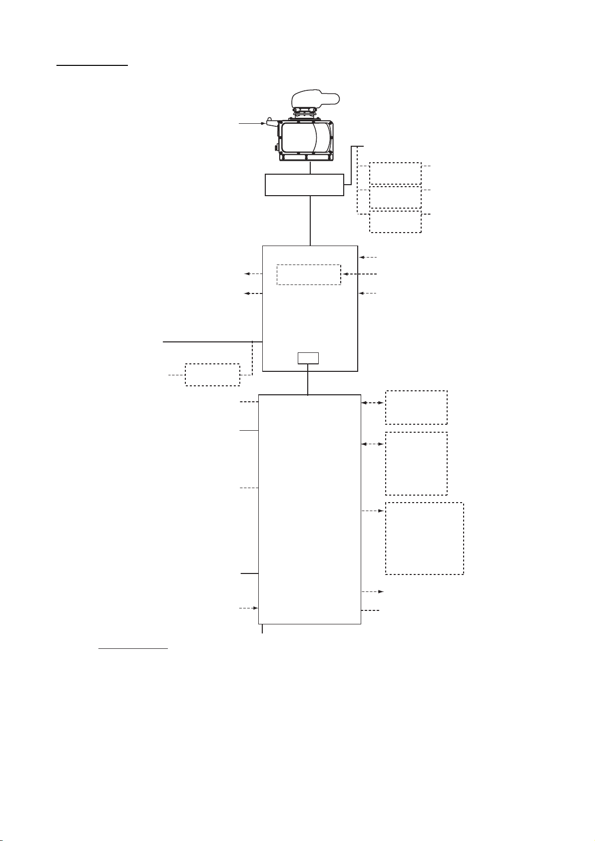
SYSTEM CONFIGURATION
FCR-2839SW
Performance Monitor
PM-51
110-115/
220-230 VAC
1ø, 50/60 Hz
440 VAC
1ø, 50/60 Hz
Sensor Adapter
Trackball Control Unit
ECDIS Control Unit
Trackball Control Unit
ANTENNA UNIT
Chassis
RSB-104/105
Sub Display 1
Sub Display 2
Transformer
RU-1803
Radar Control
Unit RCU-025
OR
RCU-026
RCU-024
OR
Radar Control
Unit RCU-025
OR
RCU-026
Monitor Unit
MU-231
Radiator
SN36AF (12 ft)
200/380 VAC, 3ø, 50 Hz
220/440 VAC, 3ø, 60 Hz
110 VAC,
3ø, 60 Hz
220 VAC,
3ø, 50 Hz
440 VAC,
3ø, 50 Hz
Transceiver Unit
RTR-082
Transformer
RU-5693
Transformer
RU-6522
Transformer
RU-5466
A-D Converter
Gyro Converter
GC-10
Gyrocompass
Heading Sensor
RPU-013
RADAR
PROCESSOR
UNIT
LAN
*2
Serial 1, 2
IEC-61162-2
(Gyro, AIS)
Serial 3 - 8
IEC-61162-1
(GPS, Log,
Echo sounder,
Wind, Alarm,
Navtex, etc.)
EC-3000
PROCESSOR
UNIT
Digital Out 1 - 6
1: System Fail
2: Power Fail
3: Normal Close 1
4: Normal Close 2
5: Normal Open 1
6: Normal Open 2
*1
VDR
xxii
Digital In (ACK IN)
Intelligent Hub
HUB-3000
Dashed lines indicate
optional or local supply
equipment.
Category of Units
Antenna Unit: Exposed to the weather
100-115/220-230 VAC
1ø, 50/60 Hz
All other units: Protected from the weather
EPFS must meet MSC.112(73); SMDE must meet MSC.96(72). GPS speed data does not meet IMO
requirements unless type approved for compliance with IMO resolution MSC.96(72). The update rate of
the gyrocompass must be better than 40 Hz (HSC) or 20 Hz (other than HSC).
*1
The MU-231 monitor meets the Category requirements for CAT 1C and CAT 1HC. If a different monitor
is to be used on IMO vessels, its effective diameter must meet the applicable Category requirements:
CAT 1C and CAT 1HC: effective diameter 320 mm or higher
CAT 2C and CAT 2HC: effective diameter 250 mm or higher
For installation, operation and viewing distance of other monitor, see its manuals
*2
Control Serial MC-3010S, Analog IN MC-3010A, Digital IN MC-3020D, Digital OUT MC-3030D
Page 25
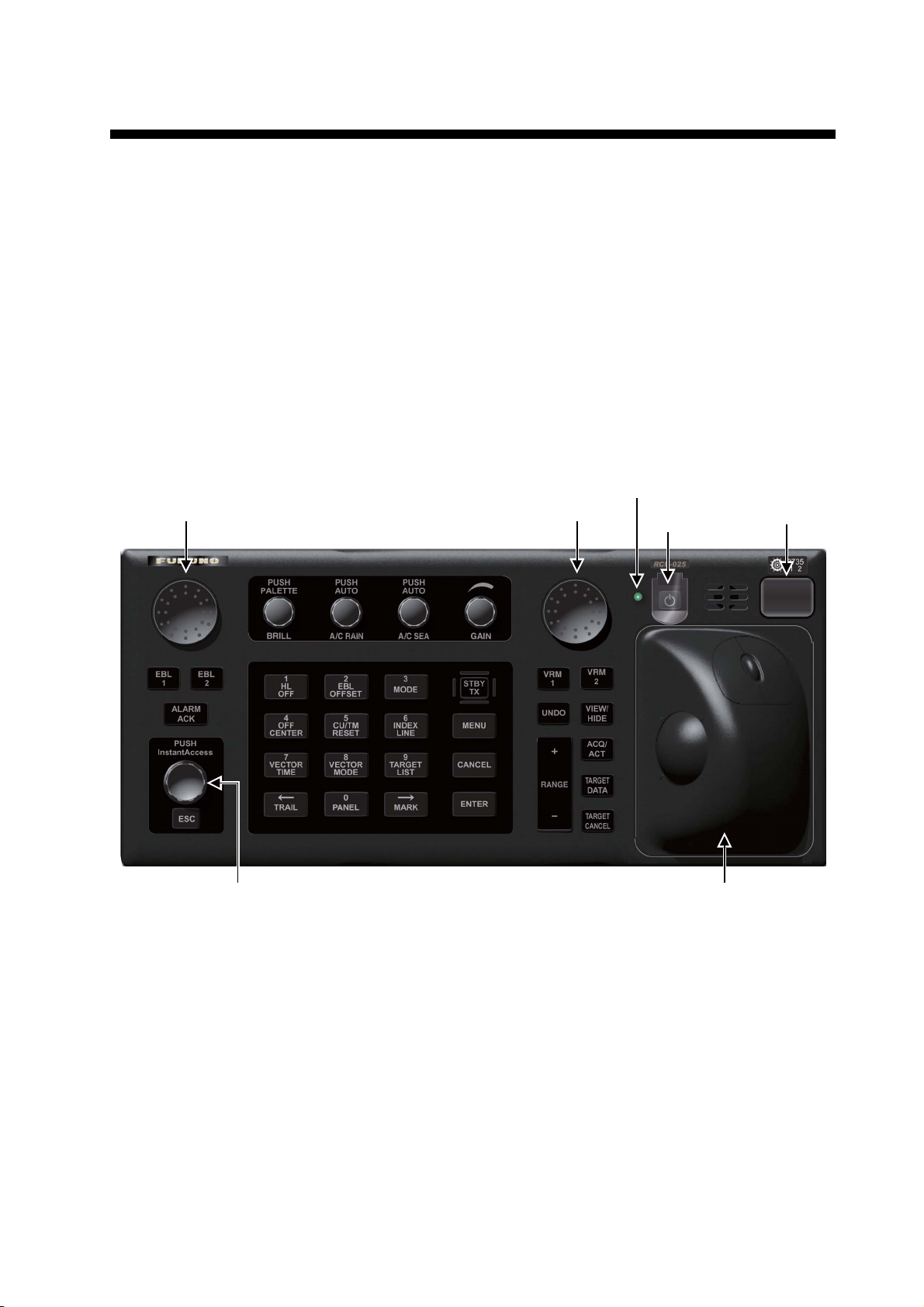
1. OPERATIONAL OVERVIEW
1.1 Units of the System
1.1.1 Radar Control Unit RCU-025
The Radar Control Unit RCU-025 consists of various controls and a trackball module
(trackball, scrollwheel and left and right buttons). The trackball module functions like
a PC mouse. The user rolls the trackball and operates the left and right buttons and
the scrollwheel to do various functions.
The RCU-025 has 28 direct access keys, five knob-type controls, two rotary encoders,
a power switch, a USB port, and a trackball module. The system can be operated with
the keys and controls or with the trackball module.
Rotary encoder
for EBL
InstantAccess knob
When you press the correct key, a single beep sounds to alert you to correct operation. For wrong operation, several beeps sound. You can select the loudness of the
beep or deactivate the beep on the [OPERATION] menu.
Rotary encoder
for VRM
Status LED
Power switch
Trackball module
USB
port
1-1
Page 26

1. OPERATIONAL OVERVIEW
Control Description
Turns the system on or off. (With a FURUNO monitor unit, the monitor is also
turned on or off with this switch.)
Status LED The color and state of the LED change according to system or alert status.
Green, lighting: Normal operation status; no alerts generated.
Green, flashing: The heater on the CPU board is on, because ambient tem-
perature is not at least 0°C. The heater takes about two minutes to warm the
equipment. The LED lights green after the heater goes off.
Red, lighting: Acknowledged alert or SYSTEM FAIL. SYSTEM FAIL occurs
when there is trouble in the Processor Unit or communication failure between
the Processor Unit and an ECDIS Control Unit. Each Control Unit detects trouble and its lamp flashes in red and the buzzer sounds. If this condition occurs
at the No. 1 ECDIS Control Unit, the SYSTEM FAIL signal is output.
Red, flashing: Unacknowledged alert or SYSTEM FAIL.
Rotary control
EBL1, EBL2
ALARM ACK • Silences the aural alarm.
InstantAccess
knob
ESC Goes back one step in current operating sequence on the InstantAccess bar.
BRILL Rotate: Adjusts the brilliance of the display (FURUNO-supplied monitor only).
A/C RAIN Rotate: Suppresses rain clutter.
A/C SEA Rotate: Suppresses sea clutter.
GAIN Adjusts the sensitivity of the radar receiver.
HL OFF • Temporarily erases everything but radar echoes when held down.
OFFSET EBL • Activates or deactivates the offset EBL.
MODE • Selects a presentation mode.
STBY/TX Toggles the radar between standby and TX.
OFF CENTER • Re-centers radar position at the cursor location.
CU/TM RESET • Course-up: Resets heading line to 000°.
INDEX LINE • Selects an index line (in the PI line box).
MENU Opens, closes the menu.
VECTOR TIME • Sets the vector time (length) for TT and AIS targets.
Rotary control: Rotates the active EBL.
EBL1, EBL2: Activates or deactivates the respective EBL.
• Acknowledges unacknowledged alert.
Selects the buttons on the InstantAccess bar.
Push: Selects a color palette.
Push: Toggles between manual and automatic rain clutter adjustment.
Push: Toggles between manual and automatic sea clutter adjustment.
• Enters the numeric 1.
• Selects like-numbered menu item.
• Enters the numeric 2.
• Selects like-numbered menu item.
• Enters the numeric 3.
• Selects like-numbered menu item.
• Enters the numeric 4.
• Selects like-numbered menu item.
• True motion: Moves own ship position 75% of the radius in stern direction.
• Enters the numeric 5.
• Selects like-numbered menu item.
• Long press to activate or deactivate selected index line.
• Enters the numeric 6.
• Selects like-numbered menu item.
• Enters the numeric 7.
• Selects like-numbered menu item.
1-2
Page 27

1. OPERATIONAL OVERVIEW
Control Description
VECTOR MODE • Sets the vector mode (relative, true).
• Enters the numeric 8.
• Selects like-numbered menu item.
TARGET LIST • Displays AIS, TT data in the target list.
• Enters the numeric 9.
• Selects like-numbered menu item.
CANCEL Cancels the changes made on the currently selected menu.
TRAIL • Goes back one page in the menu.
• Moves cursor leftward in text box.
• Turns the echo trail display on or off.
• Long-push to reset all trails.
PANEL • Adjusts the backlighting of the keys.
• Enters the numeric 0.
• Selects like-numbered menu item.
MARK • Goes forward one page in the menu.
• Moves cursor rightward in text box.
• Inputs selected mark on the radar screen, at the position selected.
ENTER Confirms selection on menu.
Rotary control
VRM1, VRM2
UNDO Undo edit or text input on radar map.
VIEW/HIDE Radar mode, chart radar mode: Shows or hides the AZ box, Drop mark box-
RANGE Selects radar range (radar and chart radar modes), chart scale (chart mode).
ACQ/ACT • TT: Acquires target selected with cursor, for target tracking.
TARGET DATA Displays the detailed data for selected TT, AIS target, in the TT/AIS informa-
TARGET
CANCEL
Trackball
module
USB port For connection of USB flash memory (FAT16 or FAT32 format). Do not con-
Rotary control: Adjusts the diameter of the active VRM.
VRM1, VRM2: Activates or deactivates the respective VRM.
es, EBLs, Mark box, PI line box, Trial box, VRMs.
Chart mode: Shows or hides the EBLs, InstantAccess bar, [Overlay/NAV
Tools] box, [Route information] box, VRMs.
• AIS: Activates cursor-selected sleeping AIS target.
tion box.
• TT: Stops tracking the cursor-selected tracked target.
• AIS: Sleeps cursor-selected activated AIS target.
• Long-push to erase all displayed TT target data.
The trackball module is the same as that used in the Trackball Control Unit
RCU-026. See the description in the next section.
nect a USB HDD or PC keyboard. The DVD drive (Maker: TEAC, Type: PUDRV10) is for chart updates.
1-3
Page 28
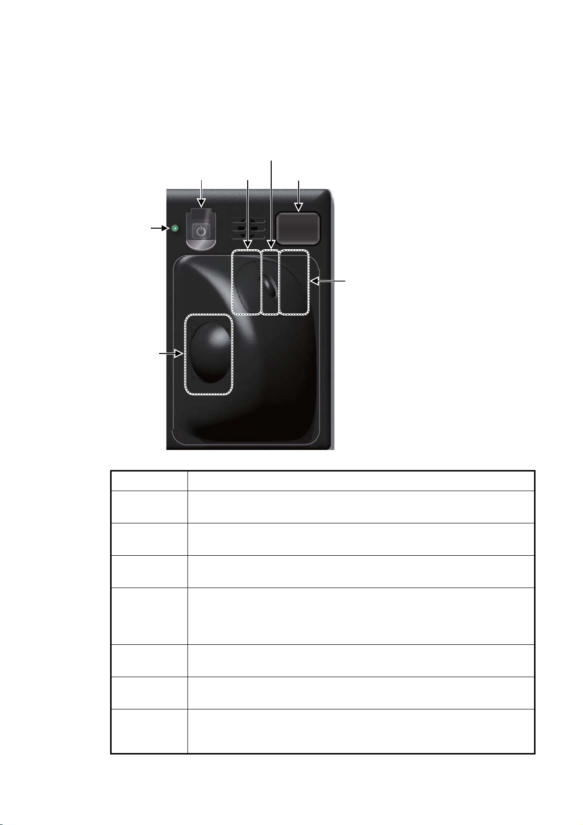
1. OPERATIONAL OVERVIEW
1.1.2 Trackball Control Unit RCU-026
The Trackball Control Unit RCU-026 has a power switch, a trackball module (trackball,
scrollwheel and left and right mouse buttons), a status LED, and a USB port. The
trackball module functions like a PC mouse; the user rolls the trackball and operates
the left and right buttons and the scrollwheel to do various functions.
Scrollwheel
Power
switch
Status
LED
Left
button
USB port
Right
button
Trackball
Control Description
Power switch Turns the system on or off. (With a FURUNO monitor unit, the monitor is
also turned on/off with this switch.)
Status LED The color and state of the LED change according to system or alert status.
See the Status LED description on page 1-2.
Left button • Does the operation related to the object selected.
• Confirms the operation done for the object selected.
Scrollwheel • Selects menu options.
• Selects chart scale.
• Sets numeric data.
• The scrollwheel does not have a "push" function.
1-4
Right button • Displays context-sensitive menu.
• Cancels operation done on the object selected.
Trackball • Moves the cursor.
• Selects an object.
USB port For connection of USB flash memory (FAT16 or FAT32 format). Do not con-
nect a USB HDD or PC keyboard. The DVD drive (Maker: TEAC, Type: PUDRV10) is for chart updates.
Page 29
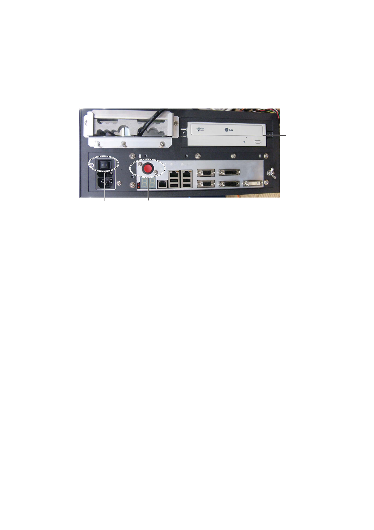
1.1.3 Processor Unit EC-3000
The Processor Unit is the heart of the chart system, and is mainly responsible for the
chart management, route planning and route navigation.
The Processor Unit has two power switches. The Mains switch controls the power
from the switchboard, and the Power switch controls the power to the chart radar system.
1. OPERATIONAL OVERVIEW
DVD
drive
Mains switch
Note 1: Do not operate the chart radar with a DVD or CD inserted in the DVD drive,
to prevent damage to the drive and media. Remove media from the drive after usage.
Insert media only to update charts. After completion of an update, remove the media
from its drive and store it in its case. Store media out of direct sunlight, in a place
where temperature and humidity are moderate and stable
Note 2: To keep the system stable, restart the unit at least once every two weeks.
Note 3: Close the lid of the DVD drive when the drive is not in use.
Power switch
1.2 How to Turn the System On/Off
Normally, leave the power switches at the front of the Processor Unit on and control
the power with the power switch on a Control Unit (RCU-025, RCU-026). The monitor
unit is powered independently.
How to power the system
Push the mains switch on the Processor Unit for the "I" position. Turn on the power
switch on the Processor Unit or a Control Unit. The start-up display appears on the
monitor.
After the power is applied, the program starts up and about one minute later the bearing scale appears. The radar then goes into three minutes of warm-up time to warm
the magnetron, which transmits radar pulses. The timer at the center of the screen
counts the time remaining for warm-up. When the timer shows 0:00, the indication
"ST-BY" appears at the screen center. The radar is now ready to transmit radar pulses. In the stand-by condition, no radar pulses are transmitted and TT nor AIS is active.
The settings on the menus are stored in a non-volatile memory (hard disk) and are
preserved when the power is turned off.
1-5
Page 30

1. OPERATIONAL OVERVIEW
Note: If the ambient temperature is less than 0°C (32°F) when the power is applied,
nothing appears on the display and the Status LED on the Control Unit flashes. This
is because the heater is warming the unit. The display appears in approx. two minutes.
How to power off the system
Press the power switch on the Processor Unit or a Control Unit. Push the Mains switch
for the "O" position.
Note: Provided that the radar was once in use with the transmitter tube (magnetron)
still warm, you can put the radar in transmit state without three minutes of warm-up. If
the Power switch was turned off by mistake or the like and you wish to restart the radar
promptly, turn on the Power switch not later than 10 seconds after power-off.
1.3 How to Adjust the Display Brilliance (FURUNO monitor)
The brilliance setting is defined according to the color palette setting. However, manual adjustment of the brilliance is also possible.
Note 1: The brilliance of the FURUNO monitor can only be adjusted from the Control
Unit. Use a serial cable for brilliance adjustment to make the connection between the
Processor Unit and the Control Unit.
Note 2: Improper brilliance may affect the visibility of information, especially on the
night display.
1.3.1 Manual brilliance adjustment
How to adjust the brilliance manually with the BRILL control
Operate the BRILL control to adjust brilliance. Turn it clockwise to increase the brilliance; counterclockwise to decrease the brilliance. Watch the brilliance level indication on the [BRILL] button (see the illustration below) to see the current brilliance level.
How to adjust the brilliance manually with the InstantAccess knob
1. Push the InstantAccess knob.
2. Rotate the knob to select the [BRILL] button then push the knob to show the bril-
liance adjustment window.
Current brilliance level
1-6
[BRILL]
button
Calibration state
(CALIB or UNCALIB)
3. Push the knob, rotate the knob to set the brilliance then push the knob to confirm
the setting. The calibration state indication changes to "UNCALIB".
4. Rotate the knob to select the [CALIB] button then push the knob to calibrate the
brilliance. The calibration state indication changes to "CALIB".
[CALIB]
button
Page 31

How to adjust the brilliance manually using the trackball module
1. Click the [BRILL] button on the InstantAccess bar to show the brilliance adjustment window.
2. For coarse adjustment, put the cursor on a location within the slider bar area
then push the left button. For fine adjustment, put the cursor on the end of the
slider bar and roll the trackball while holding down the left button.
3. Release the left button to confirm setting. The calibration state indication changes
to "UNCALIB".
4. Click the [CALIB] button to calibrate the brilliance. The calibration state indication
changes to "CALIB".
1.4 Operating Modes
This chart radar has three operating modes:
• The radar mode provides the traditional radar display.
• The chart radar mode overlays the electronic chart on the radar image.
1. OPERATIONAL OVERVIEW
• The chart for radar mode shows the electronic charts.
1.4.1 How to select an operating mode
Click the [Operating Mode] button to select desired mode from the pull-down list. Select [ RADAR] for the radar or chart radar mode (see section 1.5.2), or [CHART for RADAR] for the chart mode.
[Operating Mode] button
1.4.2 Limitations when using the chart radar mode
The presentation mode can be course-up RM, north-up RM, or north-up TM. The presentation mode is automatically switched to north-up RM if the mode is head-up at the
time the chart radar mode is selected.
1-7
Page 32

1. OPERATIONAL OVERVIEW
1.5 Display Screens
All display screens have operational buttons, boxes and indications, and display markers. Click a button or indication to execute the related operation. Context-sensitive
menus are available with several boxes outside the display area and objects inside the
display area. Right-click the appropriate box or object to show the related context-sensitive menu.
Monitor viewing distance
The optimal viewing distance for the FURUNO-supplied monitors is 1020 mm.
1.5.1 Radar display
The illustration below shows the markers, data, etc. as they appear on the FURUNO
19-inch monitor unit. The layout for the 23-inch monitor unit is similar.
Message
area
35
26
34
32
33
31
29
28
12
27
11
30
24
NAV data
-30 -20 -10 min m
N
W
S
Route 1 Route 2
0
Depth :
10
20
Water
30
TEMP :
40
50
REL :
Wind : 12.1 m/s
E
Current :
22.5 m
10.5°C
006.3°R
121.3°R
1.7 kn
No. Name Description
1 Status bar • Selects an antenna.
• Selects the mode.
• Adjusts the radar picture.
• Displays radar operational messages. See section 1.6.
2 Sensor information
box
Shows your ship's heading, heading source, ship's speed, water
tracking speed, speed source, course over ground, speed over
ground, position source.
Note: Position source shall meet the requirements of IMO
MSC.112(73).
1-8
Page 33

1. OPERATIONAL OVERVIEW
No. Name Description
3 Menu Drop-down menu with various radar and chart functions.
4 Information box Provides various navigation data and route information.
5 TT/AIS setting box Sets the parameters for TT and AIS targets.
6 Trail box Sets the parameters for the target trails.
7 Alert box Shows alert messages by alert name and alert number.
• Unacknowledged or regenerated warning alerts flash in red
(alarm) or yellow-orange (warning).
• Acknowledged alerts are shown in normal video.
8 Acquisition zone box Sets an acquisition zone for TT, AIS.
9 VRM boxes Show the range and TTG to the VRM1, VRM2.
10 Target list button Displays the TT and AIS target list.
11 Trial maneuver box Sets the parameters for the trial maneuver.
12 Drop mark 2 box Shows the bearing and range to the drop mark 2.
13 EBL boxes Show the bearing to the EBL1, EBL2.
14 Mark box Selects the mark to inscribe on the radar display.
15 Drop mark1 box Shows the bearing and range to the drop mark 1.
16 PI line box • Adjusts the direction and width of the parallel index lines.
• Activates or deactivates the parallel index lines.
17 Watch box Counts down the time remaining until the buzzer sounds to alert the
operator to view the radar picture.
18 InstantAccess bar Quick access to often-used radar, chart radar and chart functions.
For radar and chart radar functions, see section 1.7. For chart func-
tions, see section 6.1.3.
19 Tuning bar Shows tuning status.
20 Range/Presentation
mode box
21 REF point box Selects the reference point (antenna or CCRP) for measurements
22 Heading line Indicates ship's heading.
23 Bearing scale The bearing scale provides an estimate of the bearing to a target.
24 Cursor position box This box shows
25 EBL1 Measures the bearing to a target.
26 EBL2 Measures the bearing to a target.
27 VRM1 Measures the range to a target.
28 VRM2 Measures the range to a target.
29 Drop mark 1 Find the range and bearing to drop mark position.
30 Drop mark 2 Find the range and bearing to drop mark position.
31 Antenna marker A cross marks antenna position.
32 Own ship marker An inverted “T” marks your ship’s position.
33 Stern marker Marks location of stern.
34 North marker Marks North.
35 Range rings Provide an estimate of the range to a target.
• Selects the radar range.
• Selects the presentation mode.
(range, bearing, etc.) and markers (position, etc.)
• Latitude and longitude of the cursor position.
• Range and bearing to the cursor position.
• TTG to the cursor position.
1-9
Page 34

1. OPERATIONAL OVERVIEW
How to minimize, maximize the boxes at the bottom of the screen
The boxes at the bottom of the screen that contain an arrow can be minimized. Click
the arrow to minimize the box. To restore maximum size, click the minimized box.
Click arrow
to minimize.
Note: The respective VRM or EBL is erased from the screen when the corresponding
VRM or EBL box is minimized.
1.5.2 Chart radar display
The chart radar display overlays an electronic chart on the radar picture. To switch between the radar and chart radar displays, click the [Chart ON/OFF] button on the InstantAccess bar.
Click here
to maximize.
Click to hide,
show chart.
1-10
Page 35

1.5.3 Chart display
The chart display shows only the electronic chart. Click the [Operating Mode] button
to select [CHART for RADAR] to activate this display. See Chapter 6 for a description
of the chart display.
Select [CHART for RADAR]
1. OPERATIONAL OVERVIEW
1-11
Page 36

1. OPERATIONAL OVERVIEW
1.6 Status Bar
The Status bar is displayed at the top of screen in all modes. This bar provides, in the
radar and chart radar modes, buttons for selection of the mode, antenna and chart database, and adjustment of the radar picture.
For a description of the Status bar used in the chart mode, see section 6.1.2.
1.6.1 Status bar for radar, chart radar mode
No. Button name Description
1 Display Mode Selects a mode: radar or chart for radar.
2 STBY TX Toggles the radar between stand-by and transmit.
3 Antenna Selects an antenna.
4 Picture preset Presets the radar controls for specific navigation purpose; for example,
congested waters.
5 Chart database Selects the IMO chart database (base, primary, standard or all). Available
in the chart radar mode.
6 RAIN Reduces rain clutter.
7 SEA Reduces sea clutter.
8 GAIN Adjusts the gain of the radar receiver.
9 Settings Manages user profiles; opens the Settings menu.
10 Date Displays the date and whether the time indication is local or UTC.
11 Time • Displays the date.
• Selects the time to use, local or UTC.
• Sets the time difference between local and UTC (to use local time).
12 Spinner Rotates clockwise if the system is working properly.
1-12
Picture freeze
If the picture freezes, the picture is not updated. After the picture freezes,
the buzzer sounds and the Status LED blinks in red. Reset the power to re-
store normal operation.
Page 37

1. OPERATIONAL OVERVIEW
1.6.2 How to operate the buttons, slider bars on the Status bar
The Status bar has three types of controls: toggle button, drop-down list button and
slider bar. You operate the buttons and bars with the trackball module.
Control type Example of control
Toggle button
A toggle button alternately selects one of two
functions assigned to the button. For example,
the [STBY TX] button toggles the radar between
stand-by and TX. The background color of the
[STBY TX] button momentarily changes to lightblue when switching from standby to TX.
Drop-down list button
A drop-down list button provides a list from which
to select an option related to the label on the button. A drop-down list button is identified by a triangle on the button’s bottom-right corner. The
[Chart database] button, shown in the right figure,
is an example of a drop-down list button.
Click button to show
drop-down list.
Slider bar
The slider bars provide for adjustment of the radar picture. [GAIN], [SEA] and [RAIN] are slider
bar buttons. To adjust the bar coarsely, put the
cursor at any location within the slider bar area
then push the left button. For fine adjustment, put
the cursor at the end of the slider bar and roll the
trackball while holding down the left button. Release the button to finish.
1-13
Page 38

1. OPERATIONAL OVERVIEW
1.7 InstantAccess Bar
The InstantAccess bar runs vertically along the
left edge of the screen and is displayed always.
This bar provides, in the radar and chart radar
modes, buttons for adjustment of the radar picture
and chart, AIS operations, display brilliance control (FURUNO monitor only), MOB, screenshot,
etc.
For a description of the InstantAccess bar used in
the chart mode, see section 6.1.2.
1-14
13
Radar
mode,
map
ON
Radar
mode,
chart
ON
Page 39

1. OPERATIONAL OVERVIEW
No. Button name Description
1 PULSE Selects radar pulse length.
2 TUNE Select the radar receiver tuning method, automatic or manual, and man-
ually tunes the radar receiver.
3 IR Activates or deactivates the interference rejector.
4 ES Activates or deactivates the echo stretch.
5 EAV Activates or deactivates the echo averaging.
6 HL OFF Temporarily erases everything but radar echoes.
7 CU/TM reset Resets ship's position in course-up and true motion modes.
8 MAP ON/OFF Shows or hides the radar map marks on the radar display, in the radar
mode.
9 CHART ON/OFF Shows or hides the electronic chart.
10 Chart Disp Shows, hides various chart objects. Shown in the chart radar mode. See
section 2.37.2.
11 OWN AIS Shows the [VOYAGE DATA] menu, to set your ships AIS data.
12 Displays screen for “received AIS message.”
13 Selects a color palette.
14 Adjusts the brilliance of a FURUNO monitor.
15 MOB Enters the MOB mark at the current position.
16 Takes a screenshot.
17 Restore previous condition in radar map and text input.
1-15
Page 40

1. OPERATIONAL OVERVIEW
1.7.1 How to operate the buttons on the InstantAccess bar
The InstantAccess bar has three types of buttons: toggle button, drop-down list button,
and slider bar button. (The MOB and Capture buttons are special buttons.) The buttons can be operated with the trackball module or the InstantAccess knob. This section shows you how to use the InstantAccess knob.
Toggle button Drop-down list button Slider bar button
A drop-down list button provides the
PUSH
functions related to the label on the
button. This type of button is identified by the triangle at the bottom-right
corner of the button.
[Palette]
button
Palette list
1. Push the InstantAccess knob to enable its use with the InstantAccess bar.
2. Rotate the InstantAccess knob to select a button. The background color of the
button selected is light-blue.
3. Do one of the following depending on button type.
1) Toggle button: Push the knob to select setting.
2) Drop-down list button or slider bar: Rotate the knob to select an item or ad-
just the slider bar. Push the knob to confirm your selection.
Note: You can use the ESC key to go back one step in the current operating
sequence.
1.8 Sensor Information, Datum Box
The Sensor, datum information box displays
the sensor data and the name of the datum in
use. The sensor indications and names are
colored according to sensor state. See the table on the next page.
• HDG: Heading and its source.
• SPD: Longitudinal speed and its source.
The direction of transverse speed is indicated with arrows, X, Starboard, W, Port.
• COG: Course over ground and its source.
• SOG: Speed over ground and its source.
• POSN: Latitude and longitude position of
own ship and its source.
• Datum: Chart datum (WGS84, WGS72,
etc.) in use. No datum appears when there
is no datum sentence.
Note: The position source shall meet
the requirements of IMO MSC.112(73).
1-16
Page 41

1. OPERATIONAL OVERVIEW
Color of nav data indications and sensor name
The color of the nav data indications and sensor names changes according to the
state of the sensor data. The table shown below provides basic indication and color
meanings. For detailed information, see Appendix 4. When no sensor data is received,
the sensor source indication is blank and the related indication shows asterisks.
Nav data indication
Color of nav data
indication
Green White Sensor is normal.
Yellow White Validity of data is low or offset
is applied.
Red Red Validity of data is critically low.
Green, data shown
with asterisks
(***.*)
Yellow Yellow Data is input manually (dead
Color of
sensor name
No display Data is not being received.
reckoning).
State
1-17
Page 42

1. OPERATIONAL OVERVIEW
1.9 How to Select a Color Palette
This radar provides three sets of color and brilliance sets (palette), day, dusk and
night, to match any ambient lighting condition. The default specifications of each palette are as shown in the table below. The panel dimmer setting is automatically
changed, and the number of steps depends on the color palette selected.
Palette
Day-gray
Day-blue
Dusk-gray
Dusk-blue
Night-gray
Night-blue
Brilliance
Panel dimmer
19" monitor 23" monitor
110 cd/m
110 cd/m
50 cd/m
50 cd/m
5 cd/m
5 cd/m
2
120 cd/m
2
120 cd/m
2
2
2
2
50 cd/m
50 cd/m
5 cd/m
5 cd/m
2
2
2
2
2
2
To select a palette, do the following:
1. Click the [Palette] button.
[Palette]
button
(step)
Text
color
Background
color
15 White Gray
15 White Blue
7 Light gray Dark gray
7 Light gray Dark blue
3 Orange Dark gray
3 Light gray Dark blue
2. Click[Day], [Dusk] or [Night] as appropriate. For example, select [Day] to show its
options.
3. Click the palette (gray, blue) desired.
Note: A palette can also be selected by pushing the BRILL control on the Control Unit.
1-18
Page 43

1.10 Menu Overview
The menu consists of eight main menus and several sub menus. You can operate the
menu with the Radar Control Unit or trackball module. The system closes open menus
whenever there is no menu operation for 30 seconds.
1.10.1 Basic menu operation
1. Open the main menu.
Control Unit: Press the MENU key.
Trackball module: Click the menu title bar at the right side of the display.
1. OPERATIONAL OVERVIEW
Menu title bar
2. Select a menu.
Control Unit: Press the corresponding numeric key. For example, press the 3 key
to show the [NAV TOOL] menu.
Trackball module: Click the menu desired. The current selection is highlighted in
green.
Click
[3 NAV TOOL]
OR
press the
3 key.
3. Select a menu item.
Control Unit: Press the corresponding numeric key.
Trackball module: Click the menu item desired. The current selection is highlighted in green.
4. Select a menu option.
Control Unit: Press the corresponding numeric key. The current selection is highlighted in orange.
Trackball module: Spin the scrollwheel. The current selection is highlighted in orange.
5. Confirm your selection.
Control Unit: Press the ENTER key.
Trackball module: Push the left button.
Note: Hereafter, "select" in a menu operating procedure means to press the applica-
ble numeric key on the Control Unit or push the left button on the trackball module.
1-19
Page 44

1. OPERATIONAL OVERVIEW
Keys, buttons to use for navigation in menus
Control Unit
MENU key: Open main menu, or close menu when main menu is displayed.
CANCEL key: Go back one layer in menu, or close menu when main menu is dis-
played.
←key: Return to main menu, in no. 2 layer or higher.
Trackball module
Right button: Go back one layer, or close menu when main menu is displayed.
Left button: (1) Click menu title bar to go back one layer, or close menu when main
menu is displayed, (2) Click the left arrow on the menu title bar to return to the main
menu, in no.2 layer or higher.
Menu history feature
This chart radar remembers the 10 last-used menus to help you go to recently used
menus quickly. The memorized menus are cleared when the power is turned off. Installation- and service-related menus and menus where no operation occurred are not
memorized. Menus accessed multiple times are counted as one menu.
Click the memory history buttons on the menu title bar to navigate through the lastused menus.
Menu history buttons
History back
button
History forward
button
For example, the last two used menus are [NAV TOOL] and [AIS].
Click
Click
1-20
Memorized menu no. 1
Memorized menu no. 2
Page 45

1. OPERATIONAL OVERVIEW
1.10.2 How to enter numeric data
Select the numeric data, then do one of the following:
Control Unit: Use the ten keys to enter data.
Trackball module: Spin the scrollwheel to set data then push the left button.
1.10.3 How to enter alphanumeric character data
Some operations display a software keyboard to enter alphanumeric character data.
Click to switch between
letters and symbols.
To enter characters, click applicable characters on the software keyboard. You can
switch between letter input and symbol input by clicking the key shown in the illustration above:
1-21
Page 46

1. OPERATIONAL OVERVIEW
1.11 Context-Sensitive Menus in the Radar Mode
Context-sensitive menus are available with many of the boxes and buttons surrounding the display area and objects within the display area. Right-click the boxes and buttons marked with numerals in the illustration below to show the related contextsensitive menus. If a menu is not operated within 30 seconds it is automatically closed.
For context-sensitive menus in the chart mode, see the chapter on chart overview.
1.11.1 Context-sensitive menus available with buttons and boxes
37
36
35
34
38
33
32
31
39
3229
40
30
29
°
41
28
240.8
1
2
3
RADAR
FUNCTIONS
(see next page)
4
5
6
8
23
25
°
0.088
2627
24
13
15
17
11
18
7
10
9
12
14
16
20
21
2019
22
No. Box name Menu No. Box name Menu
1 Adjust Local Time Set Local Time 6 TT TT OFF / MAN /
AUTO / MAN/AUTO,TT Menu, Symbol Menu
2 Cursor Position Range-Bearing Po-
sition, X-Y Position,
Cursor Menu
3 Sensor Information Select Sensor, OS
INFO Menu
4 AIS Info Expanded AIS Data,
AIS Message
7 AIS DISP OFF / FILT /
ALL, AIS Menu,
Symbol Menu
8 Vector OS Vector Menu,
Target Vector Menu
9 Vector Time Vector Time (30 s -
60 min), OS Vector
Menu, Target Vector
Menu
1-22
Page 47

1. OPERATIONAL OVERVIEW
No. Box name Menu No. Box name Menu
5 Association Association OFF/
TT/AIS, Association
Menu
11 CPA Range CPA Range
(0.5 - 6.0 NM)
12 CPA time CPA Time
(1 - 15 min)
13 AIS CPA Auto Activate Menu 29 EBL1 EBL1 OFF, EBL-
14 Auto Activate OFF, AUTO ACT
FILT, AUTO ACT
ALL, Auto Activate
Menu
15 Lost TGT TT Lost Filter Menu,
AIS Lost Filter Menu
16 Lost TGT Filter OFF, FILT, ALL, TT
Lost Filter Menu,
AIS Lost Filter Menu
17 Past POSN Past POSN Menu 33 Watch Watch Time
18 Past POSN time Past POSN Time
(OFF, 30 s - 6
min)Past POSN
Menu
19 Trail Trail All Clear, Trail
Menu
20 Trail Time Past POSN Time
(OFF, 30 s - 6 min),
Past POSN Menu
21 Trail/Past POSN
Reference
22 Alert List Alert List/Log Win-
23 Trial Trial Mode, Trial
24 AZ Acquisition Zone
25 Drop Mark2 Drop 2 Off 41 Customize Echo Customize Echo
26 VRM2 VRM2 OFF, EBL-
True-G(S), REL,
Past POSN Menu,
Trail Menu
dow
Maneuver Menu
Menu
VRM Menu
10 Vector Reference True-G(S), REL, OS
Vector Menu, Target
Vector Menu
27 VRM1 VRM1 OFF,
EBL-VRM Menu
28 EBL2 EBL2 OFF,
EBL-VRM Menu
VRM Menu
30 Drop Mark1 Drop 1 Off
31 Mark Mark Color (B-type
only), Mark Position,
MAP File, Edit Map
Comment, Map
Mark Menu
32 PI Line Number of PI Line,
Reset PI Line,
PI Menu
(OFF, 6 - 20 min)
34 Brill Menu Brill Menu
35 Chart ON/OFF Chart Display Menu
36 MAP ON/OFF Radar Map Menu,
Route Menu, Event
Menu, User Chart
Menu
37 TUNE Tune Initialize
38 PULSE Pulse Menu
39 RANGE Range Scales
(0.125 - 96 NM)
40 Antenna Selection ANT Select Menu
Menu
1-23
Page 48

1. OPERATIONAL OVERVIEW
1.11.2 Context-sensitive menus in the display area in the radar and chart radar modes
Right-click anywhere in the display area in the radar and chart radar modes to show
the context-sensitive menu.
Target Data/ACQ/ACT: For cursor-selected TT or
AIS target, display target data, acquire target for TT,
or activate sleeping AIS target.
Target Cancel: Cancel tracking on selected tracked
target (erase target), sleep activated AIS target.
Off Center: Off center the display.
EBL Offset: Offset EBL1, EBL2 (to measure range
and bearing between two targets).
Zoom Set: Select zoom area.
Area Select: Specify the area where to delete, copy
marks.
Mark Delete: Delete cursor-selected mark. Greyed
out when radar map is off.
Mark Copy: Copy cursor-selected mark. Greyed out
when radar map is off.
Own Ship Offset: Apply an offset to own ship
position.
REF Mark: Make cursor-selected target a reference
Radar mode, map ON
target (for use in TT). Greyed out unless TT is active.
Cursor Size: Select cursor size, large or small.
Notes Detail: Show details about cursor-selected
Notes.
MOB Delete: Delete selected MOB mark.
Radar mode, map OFF or chart ON
Area selected
This context-sensitive menu is available when an
area is created to cancel tracking on specific targets,
or delete or copy marks.
Area Target Cancel: Cancel tracking on targets within the area selected.
Area Mark Delete: Delete all marks within the area
selected.
Area Mark Copy: Copy all marks within the area selected.
Area Cancel: Cancel the area created.
1-24
Page 49

1.12 Cursor Position
Cursor data appears in the Cursor position box at the top-right position on the display.
The appearance of the box is slightly different between the 23-inch and 19-inch displays, although the content is the same.
1. OPERATIONAL OVERVIEW
Cursor position
(lat/lon)
Bearing and
range to cursor
position
x and y
coordinates of
cursor position
Time to go to
cursor position
Click indication to switch
between bearing and range and
x and y coordinates.
The indication below the cursor position can show the range and bearing to the cursor
or x-y coordinates of the cursor position. Click that indication and select [Range-Bearing position] or [x-y position] as appropriate. For the X-Y coordinate display, the
Y-axis is the heading line, right/top is "plus" and left/lower is "minus".
Note 1: The cursor bearing can be selected to true or relative with [1 CURSOR BEARING] in the [CURSOR] menu. Right-click the indication and select [Cursor Menu] to
open the [CURSOR] menu.
Note 2: The cursor position is shown as "---.-" when the cursor is not within the effective display area.
Note 3: For the Cursor position box that appears in the Chart mode, see section 6.6.
1.13 How to Select Sensor Settings
This radar system accepts navigation data input two ways: System or Local. System
shares sensor data among multiple radars in a network. Sensor priority is also commonly shared among the radars. Local selects a sensor outside the network.
1. Right-click anywhere in the Sensor information box to show the context-sensitive
menu.
g]
Select Sensor
[OS Info Menu]
2. Click [Local] or [System] as applicable.
Note: The sensor system can also be selected in the chart mode through this pro-
cedure and through the menu. Open the menu then select [7 OWN SHIP INFO]
followed by [1 SENSOR].
System
Local
[Setting]
1-25
Page 50

1. OPERATIONAL OVERVIEW
1.14 How to Enter Ship Speed
The TT and azimuth stabilized presentation modes require own ship speed input and
compass signal. The speed can be entered automatically from a speed log (STW,
SOG) or GPS (SOG), or manually on the menu. Note that the FURUNO GPS Navigator GP-150 provides COG and SOG.
1. Right-click anywhere in the Sensor information box to show the context-sensitive
menu.
g]
Select Sensor
[OS Info Menu]
System
Local
[Setting]
2. Click [Select Sensor] then click [Setting].
3. Use the arrow buttons to select the [SPD] page.
Stablilization
mode
Sensor type
selection
Check for automatic
speed input
Speed
sensor
list
1-26
Check for manual
speed input
Select to use radar as
source for speed and course
Set speed and course of drift
SPD page
4. For automatic input, follow the procedure below. For manual input, go to step
5.
1) Check [Sensors].
2) Set the priority for the speed sensors in case of Local sensor. Click the triangle
on any line then select the sensor to set as the primary source of speed. All
other sensors are then set as secondary source. Only one sensor can be pri-
Page 51

1. OPERATIONAL OVERVIEW
mary while the others can be secondary. If a speed sensor is changed from
secondary to primary state and another speed sensor was selected as primary, then that sensor previously selected to primary state is then automatically
selected to secondary state.
3) Select [Bottom] or [Water] at [Stabilization Mode] to set the stabilization method. Select [Bottom] for GPS or [Water] for a speed log.
4) Check [LOG] or [GPS] at [Sensor Type] to select the source of speed data.
5) Go to step 6.
5. For manual input, set the stabilization mode for [Water] and check [Manual].
Click the manual box to show the up and down arrows then click appropriate arrow
to set speed.
Note: For set and drift, see chapter 16.
6. Click the [OK] button to save the settings then click the [MENU] bar to close the
menu.
Notes on speed input
• IMO Resolution A.823(19) for TT requires that a speed log to be interfaced with a
TT should be capable of providing through-the-water speed (forward speed).
• A single-axis water log cannot measure speed when the wind is coming from the
leeway direction.
• When AIS is active, "Manual", "Reference SPD" and "Set Drift" are shown in gray
to indicate that they are not available for selection.
1-27
Page 52

1. OPERATIONAL OVERVIEW
1.15 How to Enter Heading
Choose manual or automatic heading input as follows:
1. Right-click anywhere in the Sensor information box to show the context-sensitive
menu.
2. Click [Select Sensor] then click [Setting].
3. Use the arrow buttons to select the [HDG] page.
Check for automatic
heading input
GY001
Heading
sensor
list
Analog gyro
heading
Manual heading
input (not shown
on IMO type)
GY002
HDG page
4. For automatic input, follow the procedure below. For manual input, go to step
5.
1) Check [Sensors].
2) Set the priority for the heading sensors. Click the triangle on any line then se-
lect the sensor to set as the primary source of heading. All other sensors are
then set as secondary source. Only one sensor can be primary while the others can be secondary. If a heading sensor is changed from secondary to primary state and another heading sensor was selected as primary, then that
sensor previously selected to primary state is then automatically selected to
secondary state.
3) Go to step 6.
5. For manual input, check the [Manual] box. Click the heading input box to show
the up and down arrows. Click the arrows to set heading.
6. Click the [OK] button to save the settings then click the [MENU] bar to close the
menu.
1-28
Page 53

1.16 How to Mark MOB Position
Use the MOB (man overboard) feature to mark the position of man overboard on the
display screen. Click the [MOB] button (in any mode) on the InstantAccess bar.
[MOB]
button
The MOB mark instantly appears at the geographical position of your ship when the
button is clicked.
1. OPERATIONAL OVERVIEW
Up to 100 MOB marks can be saved. When the capacity for MOB marks is reached,
the oldest mark is automatically erased to make room for the latest.
To delete an MOB mark, right-click the mark to show the context-sensitive menu then
select [MOB Delete].
Exercise caution when using this feature in strong tide or current. The person will not
be at the MOB position for a very long time.
1.17 How to Offset Position
The position shown in the Sensor information box may be different from the actual position. This error affects the positioning accuracy of radar echoes, radar map and TT
and AIS symbols. If there is a difference, apply an offset to position as shown below
to compensate for the error.
1. Right-click the display area to show the
context-sensitive menu.
2. Select [Own Ship Offset] and push the
left button. The color of the cursor becomes blue.
Offset value
range, bearing)
3. Roll the trackball until the cursor is at the "correct position".
4. Push the left button to confirm.
To cancel the offset, show the context-sensitive menu then select [Reset Own Ship
Offset]. The indication [Offset] and the offset values are then erased from the display.
1-29
Page 54

1. OPERATIONAL OVERVIEW
1.18 How to Select Time Format, Set Local Time
The GPS navigator feeds time and date data to the chart radar and they appear on the
Status bar. Neither the time nor the date can be adjusted, however you can select between UTC time (default) and local time. You can switch between the local time and
the UTC time by left-clicking the Current time format indication.
Current time format
Left click: Switch between local
and UTC times
Right click: Adjust local time
To use the local time, enter the time difference between the local time and the UTC
time as shown below.
1. Right-click the Current time format indication to show the context-sensitive menu
then click [Set Local Time] to display the [Adjust Local Time] dialog box.
2. Enter the time difference between the local time and the UTC time, in hours and
minutes. Use the button on the left to select the time offset direction. Select "+" if
the local time is ahead of the UTC time, or "-" if it is behind the UTC time.
Time
1.19 How to Take a Screenshot of the Display
1-30
Click the [Capture] button on the InstantAccess bar to take a screenshot and save it
to the SSD (Solid State Drive). You can save a maximum of 100 screenshots. When
the memory for screenshots becomes full, you cannot take any more screenshots. In
this case, delete unnecessary screenshots. You cannot take a screenshot when a
menu or a dialog box is opened.
[Capture]
button
Screenshots can be copied to a USB flash memory. For how to process screenshots,
see section 23.9.
Page 55

1. OPERATIONAL OVERVIEW
1.20 The Settings Menu
The [Settings] button gives you access to the user profiles and the [Settings] menu.
The [Settings] menu has facilities for screenshot management, file management, diagnostic tests and customizing. See chapter 23.
[Settings]
button
1.21 User Profiles for Radar, Chart Radar
The [Settings] button lets you store ten sets of custom settings for brilliance settings
and color settings (echoes, TT and AIS symbols and echo trails). This allows individual
users to quickly set the system according to their preferences.
1.21.1 How to create a profile
1. Set the color settings (echoes, TT and AIS symbols, echo trail) as desired.
2. Click [ ] on the Status bar then click [Manage Profile].
3. Select a profile number from the “Profile” drop-down
list.
Note: Profiles 06-10 are disabled in the default setting. To enable a disabled profile, select the profile
to enable from the “Profile” drop-down list then uncheck [Disable this profile].
4. Click [Save Current Settings].
1.21.2 How to disable a profile
Select the profile to disable from the “Profile” drop-down list then check [Disable this
profile]. Profile 01 cannot be disabled.
1.21.3 How to restore default settings to a profile
Select the applicable profile from the “Profile” drop-down list then click [Restore Default Settings].
1.21.4 How to activate a profile
1. Click [ ] on the Status bar.
2. Click the profile number to activate.
Profiles
(enabled)
1-31
Page 56

1. OPERATIONAL OVERVIEW
1.22 How to View Chart Software Version No., Chart System Information, and Operator's Manual
You can show chart (ECDIS) program no., chart system information, and the operator's manual as follows:.
1. Click the [Operating Mode] button at the left end of the Status bar to select [Chart
for Radar].
2. Click the [?] button on the Status bar.
[?] button
3. Select [Manual] to show the operator's manual, or [About] to show chart and sys-
tem information.
On the [About] screen, click the [Version] tab to show the chart (ECDIS) software version no., conning software version no., S52 presentation library version, ENC user
permit no., and C-MAP SDK software version no. Click the [System] tab to show system information: CPU type, RAM capacity, SSD free/SSD capacity and Unified ID. The
numbers you see may be different from those in the illustration below.
XXXXXXXXXXXXXXXXXXXXXXXXXXXX
1.23 Tips (operational guidance)
This chart radar provides operational tips for the display area, InstantAccess bar and
Mark box. To get a tip, simply put the cursor on the object. For example, put the cursor
on the [Capture] button on the InstantAccess bar. The tip "Capture screenshot" appears.
1-32
Tip
If you do not need the tips, you can turn them off with [TIPS GUIDANCE] in the [INITIAL SETTING] menu.
Page 57

2. RADAR, CHART RADAR
r
OPERATION
2.1 How to Transmit
After the power is turned on and the magnetron has warmed,
"ST-BY" appears at the screen center, meaning the radar is
ready to transmit radar pulses. You can transmit by pushing
the STBY/TX key on the Control Unit, or clicking the [STBY
TX] button on the Status bar.
The radar is initially set to previously used range and pulse length. Other settings such
as brilliance levels, VRMs, EBLs and menu option selections are also set to previous
settings.
The STBY/TX key (or [STBY TX] button) toggles the radar between STBY and
TRANSMIT state. The antenna is stopped in stand-by and rotates in transmit. Set the
radar in standby when its use is not required, to conserve the life of the magnetron.
2.2 How to Tune the Radar Receiver
After the radar is transmitting, adjust the receiver to the exact frequency of the transmitter, automatically or manually. The current tuning method and tuning status is
shown at the top-left position.
[STBY TX] button
[TUNE] button
TUNE MAN: Manual tuning
TUNE AUTO: Automatic tuning
2.2.1 How to initialize tuning
Automatic tuning is initialized during the installation. However, if you feel that automatic tuning is not working properly try re-initializing the tuning. Right-click the [TUNE] button then select [Tune initialize] to start the initialization.
2.2.2 Automatic tuning
Click the [TUNE] button on the InstantAccess bar to display [TUNE AUTO].
2.2.3 Manual tuning
To tune the radar, start by setting the brilliance to a comfortable level, adjusting the
gain until the background speckle just disappears, and selecting the 48-mile range.
Then, do the following:
Tuning ba
2-1
Page 58

2. RADAR, CHART RADAR OPERATION
1. Choose a weak contact somewhere near the edge of the screen and concentrate
on that, while adjusting the gain control in small steps - allowing at least two seconds between each step - until the chosen contact is as big, bright and consistent
as possible.
2. Click the [TUNE] button on the InstantAccess bar to display [TUNE MAN].
3. Put the cursor on the tuning bar.
4. Spin the scrollwheel to tune. The best tuning point is where the bar swings maxi-
mum. The arrow below the bar shows the tuning control position; not the tuning
condition.
2.3 Presentation Modes
This radar has the following presentation modes in the radar mode:
Relative Motion (RM)
Head-up: Unstabilized.
Head-up TB: Head-up with compass-stabilized bearing scale (True Bearing) where
the bearing scale rotates with the compass reading.
Course-up: Compass-stabilized relative to ship's orientation at the time of selecting
course-up.
North-up: Compass-stabilized with reference to North.
True Motion (TM)
North-up: Ground- or sea-stabilized with compass and speed inputs.
Mode availability
Presentation
mode
Course-up Yes Yes
Head-up RM Yes No
Head-up TB RM Yes No
North-up RM Yes Yes
North-up TM Yes Yes
Stern-up* Yes No
*Not available with IMO or A type.
Availability
Radar Chart radar
2.3.1 How to select a presentation mode
2-2
How to select a presentation mode from the Control Unit
Push the MODE key consecutively to select radar presentation mode desired. The
Range/Presentation mode box shows the current presentation mode.
Page 59

2. RADAR, CHART RADAR OPERATION
How to select a presentation mode from the Range/Presentation mode box
Selection method 2
Click to show drop-down list.
Click desired mode on list.
Selection method 1
Click indication to select mode.
IMPORTANT
Loss of gyrocompass signal
When the gyrocompass signal is lost, the Alert
“Gyro xxx COM1 Error” (xxx=a number between 250 and 259 according to gyro no.) appears in the [Alert] box. After all signals are lost,
the Alert 450 “Heading Sensor Not Available”
appears, the presentation mode becomes
head-up and all TT and AIS are erased. Check
the gyrocompass and select the presentation
mode with the MODE key or the Range/Presentation mode box.
2.3.2 Description of presentation modes
Head-up mode
The head-up mode is a display in which the line
connecting own ship and the top of the display indicates own ship's heading.
The target pips are painted at their measured distances and in their directions relative to own ship's
heading.
The short line on the bearing scale is the north
marker, which indicates heading sensor north. A
failure of all the heading sensor inputs will cause
the heading readout to disappear, and the Alert 450 "Heading Sensor Not Available"
or "Gyro xxx COM1 Error" (a number between 250-259 according to gyro no.) appears
in the [Alert] box.
North marker
Heading
line
2-3
Page 60

2. RADAR, CHART RADAR OPERATION
Course-up mode
The course-up mode is an azimuth stabilized display in which a line connecting the center with the
top of the display indicates own ship's intended
North marker
Heading
line
course (namely, own ship's previous heading just
before this mode has been selected).
Target pips are painted at their measured distances and in their directions relative to the intended course, which is maintained at the 0degree position. The heading line moves in accordance with ship's yawing and course change. This mode is useful for avoiding
smearing of the picture during course change.
Head-up TB (True Bearing) mode
Radar echoes are shown in the same way as in the head-up mode. The difference
from the normal head-up presentation lies in the orientation of the bearing scale. The
bearing scale is heading sensor stabilized. That is, it rotates in accordance with the
heading sensor signal, enabling you to know own ship's heading at a glance.
This mode is available when the radar is interfaced with a gyro heading sensor. If the
gyro heading sensor fails, the bearing scale returns to the state of head-up mode.
North-up mode
The north-up mode paints target pips at their measured distances and in their true (heading sensor) directions from own ship, north bearing maintained at
North marker
Heading
line
the top of the screen. The heading line changes its direction according to the ship's heading. Requires
heading signal.
If the compass fails, the presentation mode changes
to head-up and the north marker disappears. A failure
of the heading sensor input will cause the heading
readout to disappear, and the Alert 450 "Heading
Sensor Not Available" or "Gyro COM1 Error" (a number between 250-259 according
to gyro no.) appears in the [Alert] box.
True motion mode
Own ship and other moving objects move in accordance
with their true courses and speed. In ground stabilized
North marker
Heading
line
TM, all fixed targets, such as landmasses, appear as stationary echoes. In the sea stabilized TM without set and
drift inputs, the landmass can move on the screen. Note
that true motion is not available on the 96 nm or higher
range scale range scale. If COG and SOG (both over the
ground) are not available on the TM mode, enter the set
(tide direction) and drift (tide speed) manually referring to
a Tide Table.
2-4
Page 61

2. RADAR, CHART RADAR OPERATION
If the position of the CCRP results in a part of the bearing scale not being distinguishable, that part of the bearing scale is indicated with appropriate reduced detail.
A failure of the heading sensor input will cause the heading readout to disappear, and
the Alert 450 "Heading Sensor Not Available" or "Gyro COM1 Error" (a number between 250-259 according to gyro no.) appears in the [Alert] box.
When own ship reaches a point corresponding to 50% of the radius of the display, own
ship position is automatically reset to a point of 75% radius opposite to the extension
of the heading line passing through the display center. You can also reset the own ship
symbol manually by pushing the CU/TM RESET key, or click the [CU/TM reset] button
on the InstantAccess bar.
Heading
line
(a) True motion
is selected
North marker
(b) Own ship has reached a
point 50% of display radius
(c) Own ship is automatically
reset to 75% of display radius
2-5
Page 62

2. RADAR, CHART RADAR OPERATION
2.4 How to Select the Range Scale
The selected range scale, range ring interval and pulse length are shown at the topleft position on the screen. When a target of interest comes closer, reduce the range
scale so that it appears in 50-90% of the display radius.
Range ring interval
Range scale
Note: The IMO- and A-type radars do not have the 1 nm, 2 nm, 4 nm, 8 nm, 16 nm,
32 nm and 120 nm ranges.
How to select a range scale from the Control Unit
Use the RANGE key to select range desired. Hit the "+" part of the key to raise the
range; the "-" part to lower the range.
How to select a range scale from the Range/Presentation mode box
Method 1: Click the range scale indication.
Method 2: Click the appropriate range selection button. Click the "+" button to raise
the range; the "-" button to lower the range.
Method 3: Right-click the range scale indication to show a drop-down list of available
ranges then click a range.
2.5 Pulse Length
Range selection
buttons
The pulse length in use is displayed at the top-left position on the screen, using the
indications shown in the table below.
Pulse length
indication
L Long pulse 1.2
M1 Medium pulse 1 0.3
M2 Medium pulse 2 0.5
M3 Medium pulse 3 0.7
S1 Short pulse 1 0.07
S2 Short pulse 2 0.15
Appropriate pulse lengths are preset to individual range scales and function keys. If
you are not satisfied with the current pulse length settings, you can change them as
shown below.
Meaning Pulse length (μs)
2-6
Page 63

2.5.1 How to select a pulse length
You can select the pulse length for the 0.5 to 24 nm range
scales as shown below.
1. Open the menu then select [1 ECHO], [1 CUSTOMIZE
ECHO] and [8 PULSE] menus to show the [PULSE]
menu.
2. Do one of the following:
Control Unit: Press appropriate numeric key to select
corresponding item number.
Trackball module: Click appropriate item.
3. Select desired option by pressing the numeric key
pressed at step 2 or spinning the scrollwheel.
4. To confirm selection, press the ENTER key on the Control Unit, or push the left button.
2.5.2 How to change the pulse length
2. RADAR, CHART RADAR OPERATION
1. Click the [Pulse] button at the top of the InstantAccess bar.
2. Click a pulse length.
2.6 How to Adjust the Sensitivity
The GAIN control (or [Gain] button) adjusts the sensitivity of the receiver. The proper
setting is such that the background noise is just visible on the screen. If you set up for
too little sensitivity, weak echoes may be missed. On the other hand excessive sensitivity yields too much background noise; strong targets may be missed because of the
poor contrast between desired echoes and the background noise on the display.
Adjust the gain so background noise is just visible on the screen.
How to adjust the sensitivity from the Control Unit
While monitoring the radar image and the gain slider bar, operate the GAIN control to
adjust the sensitivity.
How to adjust the sensitivity from the trackball module
For coarse adjustment, put the cursor within the slider bar area then push the left
button. For fine adjustment, put the cursor at the end of the slider bar then roll the
trackball while pushing and holding down the left button. Release the button to finish.
Put cursor on slider bar and push and
hold left button. Drag cursor to new
location then release left button.
2-7
Page 64

2. RADAR, CHART RADAR OPERATION
2.7 How to Suppress Sea Clutter
Echoes from waves cover the central part of the display with random signals known
as sea clutter. The higher the waves, and the higher the antenna above the water, the
further the clutter will extend. When sea clutter masks the picture, suppress it with the
A/C SEA control (or [SEA] on the Status bar), either manually or automatically.
When both sea clutter and rain clutter are reduced, the sensitivity is decreased more
than when only one is adjusted. For that reason adjust them carefully.
The echo average is useful for reducing reflections from the sea surface. However,
high-speed targets are harder to detect than stationary ones when the echo average
is active.
2.7.1 How to reduce sea clutter automatically
Auto A/C SEA allows for fine-tuning of the A/C SEA circuit, within ±20 dB. Accordingly,
with the bar reading set to 100, gain is not lowered to minimum as with manual A/C
SEA on close-in ranges. Further, the auto A/C SEA level is low because the average
value of the original input echo is low in areas where there are no sea surface reflections. For example, when the ship is alongside a quay and the radar picture shows
echoes from both land and sea, you can observe the size of echoes because the STC
curve is different depending size of echoes.
To get automatic adjustment of sea clutter, do one of the following:
Control Unit: Push the A/C SEA control to display
[AUTO] on the [SEA] mode indication on the Status
bar.
Trackball module: Click the [SEA] mode indication
to display [AUTO].
2.7.2 How to reduce sea clutter manually
The A/C SEA control reduces the amplification of echoes at short ranges (where
clutter is the greatest) and progressively
increases amplification as the range increases, so amplification will be normal
at those ranges where there is no sea
clutter.
The proper setting of the A/C SEA
should be such that the clutter is broken
up into small dots, and small targets become distinguishable. If the setting is set too
low, targets will be hidden in the clutter, while if the setting is too high, both sea clutter
and targets will disappear from the display. In most cases adjust the control until clutter has disappeared to leeward, but a little is still visible windward.
Sea clutter at
screen center
SEA mode indication
A/C SEA adjusted; sea
clutter suppressed
2-8
Be careful not to remove all sea clutter, because you may erase weak echoes. Further, the possibility of losing weak echoes is greater when you use both A/C SEA and
A/C RAIN to reduce clutter.
To reduce sea clutter manually, do one of the following:
Page 65

2. RADAR, CHART RADAR OPERATION
Control Unit: Push the A/C SEA control to display [MAN] on the [SEA] mode indication on the Status bar. Rotate the A/C SEA control to adjust the sea clutter.
Trackball module: Click the [SEA] mode indication on the Status bar to display
[MAN]. For coarse adjustment, put the cursor within the slider bar area then push the
left button. For fine adjustment, put the cursor at the end of the slider bar then roll the
trackball while pushing and holding down the left button. Release the button to finish.
2.8 How to Suppress Rain Clutter
The vertical beam width of the antenna is designed to see surface targets even when
the ship is rolling. However, by this design the unit will also detect rain clutter (rain,
snow, or hail) in the same manner as normal targets.
The A/C RAIN control adjusts the receiver sensitivity as the A/C SEA control does but
rather in a longer time period (longer range). The higher the setting, the greater the
anti-clutter effect. When echoes from precipitation mask solid targets, adjust the A/C
RAIN control to split up these unwanted echoes into a speckled pattern, making recognition of solid targets easier.
Be careful not to remove all rain clutter, because you can erase weak echoes. Further,
the possibility of losing weak echoes is greater when you use both A/C RAIN and A/C
SEA to reduce clutter.
Note 1: When both sea clutter and rain clutter are reduced the sensitivity is decreased
more than when only one is adjusted. For that reason adjust them carefully.
Note 2: The echo average (see 2.16) is useful for reducing reflections from the sea
surface. However, high-speed targets are harder to detect than stationary ones when
the echo average is active.
2.8.1 How to reduce rain clutter automatically
Control Unit: Push the RAIN control to display
[AUTO1], [AUTO2], [AUTO3] or [AUTO4] on RAIN
mode indication on the Status bar. The higher the
number the greater the degree of rain clutter reduction.
Trackball module: Click the [RAIN] mode indication
on the Status bar to display [AUTO1], [AUTO2],
[AUTO3] or [AUTO4]. The higher the number the
greater the degree of rain clutter reduction.
RAIN mode indication
2-9
Page 66

2. RADAR, CHART RADAR OPERATION
2.8.2 How to reduce rain clutter manually
Control Unit: Push the RAIN control to display [MAN] on the [RAIN] mode indication
on the Status bar. While watching the radar picture, adjust the RAIN control to reduce
the clutter.
Trackball module: Click the [RAIN] mode indication on the Status bar to show [MAN].
For coarse adjustment, put the cursor within the slider bar area then push the left button. For fine adjustment, put the cursor at the end of the slider bar then roll the trackball
while pushing and holding down the left button. Release the button to finish.
Note: The detection range is reduced when the RAIN is used to show targets in rain.
Generally, the amount of rain, TX pulse length and TX frequency are factors in determining how the detection range is affected. The figures shown below illustrate this occurrence.
16
14
12
10
16 mm/h rain - short pulse
4 mm/h rain - short pulse
16 mm/h rain - long pulse
4 mm/h rain - long pulse
Reduction of Range of First Detection (NM)Reduction of Range of First Detection (NM)
Reduction of range of first detection (NM)
16 mm/h rain - short pulse
4 mm/h rain - short pulse
16 mm/h rain - long pulse
4 mm/h rain - long pulse
8
6
4
2
0
0 2 4 6 8 10 12 14 16
Original range of first detection (NM)
Reduction of rain to first detection due to rain at S-band
16
14
12
10
8
6
16 mm/h rain - short pulse
4 mm/h rain - short pulse
16 mm/h rain - long pulse
4 mm/h rain - long pulse
4 mm/h rain (short pulse)
16 mm/h rain (short pulse)
4 mm/h rain (short pulse)
16 mm/h rain (long pulse)
4 mm/h rain (short pulse)
4 mm/h rain (long pulse)
16 mm/h rain (short pulse)
2-10
4
2
0
0 2 4 6 8 10 12 14 16
Original range of first detection (NM)
16 mm/h rain (long pulse)
Reduction of rain to first detection due to rain at X-band
The author thanks the International Electrotechnical Commission (IEC) for permission to reproduce
Information from its Interantional Standard IEC 62388 ed.1.0 (2007). All such extracts are copyright of
IEC, Geneva, Switzerland. All rights reserved. Further information on the IEC is available from
www.iec.ch. IEC has no responsibility for the placement and context in which the extracts and
contents are reproduced by the author, or is IC in any way responsible for the other content or
accuracy therein.
Page 67

2. RADAR, CHART RADAR OPERATION
How to read the graph
Using the X-band graph as an example, a radar target detected in rain on the 8 nm
range scale can only be detected at the ranges shown below:
4 mm/h rain (short pulse): approx 7.5 nm
16 mm/h rain (short pulse): approx 5.6 nm
4 mm/h rain (long pulse): approx 2.6 nm
16 mm/h rain (long pulse): approx 0.9 nm
2.9 How to Measure the Range to a Target
The range to a target may be measured three ways: with the fixed range rings, with
the cursor, or with the VRM.
Use the range rings to obtain a rough estimate of the range to a target. They are the
concentric solid circles about own ship, or the sweep origin. The number of rings is
automatically determined by the selected range scale and their interval is displayed in
the Range/Presentation mode box at the top-left position on the screen. Count the
number of rings between the center of the display and the target. Check the range ring
interval and judge the distance of the echo from the inner edge of the nearest ring.
The range rings can be turned on/off with [RANGE RING] on the [NAV TOOL] menu.
2.9.1 How to measure the range by using a VRM
There are two VRMs, No. 1 and No. 2, which appear as dashed rings so that you can
distinguish them from the fixed range rings. The two VRMs can be distinguished from
each other by the different lengths of their dashes; the dashes on the No. 2 VRM are
longer.
000
010
VRM1
280
270
260
350
340
330
320
310
300
290
250
240
230
220
210
200
190
020
030
150
160
170
180
040
050
130
140
VRM1
TTG 45:02
0.66
Target
060
070
080
090
100
110
120
NM
VRM2
VRM2
TTG 99:59
1.18
NM
How to measure the range from the Control Unit
1. Press the VRM 1 or VRM 2 key to display desired VRM.
2. Rotate the VRM rotary control to align the active variable range marker with the
inner edge of the target of interest and read its distance at the bottom-right position on the screen. Each VRM remains at the same geographical distance when
you operate the range control. This means that the apparent radius of the VRM
ring changes in proportion to the selected range scale.
To erase a VRM, press the VRM 1 or VRM 2 key to erase corresponding VRM.
2-11
Page 68

2. RADAR, CHART RADAR OPERATION
How to measure the range from the trackball module
1. Click the title bar on a VRM box to activate the corresponding VRM.
2. Spin the scrollwheel or use the trackball to align the active variable range marker
with the inner edge of the target of interest and read its distance at the bottomright position on the screen. Each VRM remains at the same geographical distance when you operate the range control. This means that the apparent radius of
the VRM ring changes in proportion to the selected range scale set the outer edge
of the VRM on the inner edge of the target.
3. To anchor the VRM, push the left button.
To turn off a VRM, click the arrow in the applicable VRM box. The VRM disappears
and the VRM box is minimized.
2.9.2 How to set VRM attributes
You can customize the VRMs to suit
your needs.
1. Open the menu then select [3
NAV TOOL] and [2 EBL VRM] (B
type) or [2 EBL/VRM CURSOR]
(IMO and A types) to display the
[EBL/VRM] menu (EBL/VRM/
CURSOR menu for the IMO and
A types).
2. For the B-type radar, select [3
VRM1] or [4 VRM2] as appropriate. Spin the scrollwheel to select
desired unit then push the left
button.
3. S el ec t [ 6 V RM TT G] (B ty pe ) or [2
VRM TTG] (IMO and A types) and then select the VRM(s) that are to show/hide
the TTG indication. [OFF] shows no TTG indication.
IMO- and A-type radars
B-type radar
2-12
4. The [LINK EBL] option for [7 VRM OFFSET] automatically activates the corresponding VRM when the offset
EBL is enabled.
5. Close the menu.
000
010
350
340
330
320
310
VRM
300
290
280
270
260
250
240
230
220
210
200
020
030
040
050
060
070
080
Offset
EBL
160
190
170
180
090
100
110
120
130
140
150
Page 69

2. RADAR, CHART RADAR OPERATION
2.10 How to Measure the Bearing to a Target
Use the Electronic Bearing Lines (EBLs) to take bearings of targets. There are two
EBLs, No. 1 and No. 2. Each EBL is a straight dashed line extending from the own
ship position up to the circumference of the radar picture. The two EBLs can be distinguished from each other by the different lengths of their dashes; the dashes on the
No. 2 EBL are longer.
Each EBL carries a range marker, or a short line crossing the EBL at right angles. Its
distance from the EBL origin is indicated at the VRM readout whether or not the corresponding VRM is displayed. The range marker changes its position along the EBL
with the rotation of the VRM control. To operate this marker, rotate the VRM rotary
control on the Control Unit, or put the cursor in the applicable VRM box and roll the
scrollwheel.
000
010
EBL bearing
EBL2
320
310
300
290
280
270
260
250
240
230
220
EBL1
128.0°R100.8°
EBL2
350
340
330
Range marker
210
200
190
R
020
030
040
140
150
160
170
180
Target
050
060
070
080
090
100
EBL1
110
120
130
EBL reference
2.10.1 How to measure the bearing
How to measure the bearing from the Control Unit
1. Press the EBL 1 or EBL 2 key to display desired EBL.
2. Rotate the EBL rotary control to bisect the target with the EBL. Read the bearing
to the target at the appropriate EBL box.
To erase an EBL, press the EBL 1 or EBL 2 key to erase appropriate EBL.
How to measure the bearing from the trackball module
1. Click the title bar on a EBL box to activate the corresponding EBL.
2. Spin the scrollwheel or use the trackball to bisect the target with the EBL.
3. To anchor the EBL, push the left button.
To turn off an EBL, click the arrow in applicable EBL box. The EBL disappears and the
EBL box is minimized.
2-13
Page 70

2. RADAR, CHART RADAR OPERATION
2.10.2 How to select bearing reference
An EBL box has an "R" (relative) if the EBL bearing is relative to own ship's heading;
"T" (true) if it is referenced to the north. True or relative indication is available regardless of presentation mode.
To change the bearing reference, click the EBL reference indication to display R or T
as appropriate. The bearing reference can also be selected on the [EBL/VRM] menu
([EBL/VRM/CURSOR] menu with the IMO- and A-type radars).
Note: When the gyrocompass heading changes, the EBL and its indication change as
follows:
Course-up, relative:
Course-up, true:
Head-up, relative:
Head-up, true:
North-up, relative:
North-up, true:
EBL indication remains the same, EBL moves.
EBL indication and EBL remain unchanged.
EBL indication and EBL remain unchanged.
EBL indication remains the same; EBL moves.
EBL indication remains the same, EBL moves.
EBL indication and EBL remain unchanged.
2.11 Collision Assessment by Offset EBL
The origin of the EBL can be placed anywhere with the trackball to enable measurement of range and bearing between two targets. This function is also useful for assessment of the potential risk of collision. It is possible to read CPA (Closest Point of
Approach) by using a VRM as shown in Figure (a) on the next page. If the EBL passes
through the sweep origin (own ship) as illustrated in Figure (b), the target ship is on a
collision course.
2.11.1 How to assess risk of collision
How to assess risk of collision from the Control Unit
1. Press the EBL1 or EBL2 key to activate an EBL.
2. Put the cursor on a target that appears as a threatening target (A in the figure on
the next page).
3. Press the EBL OFFSET key to shift the EBL origin to the cursor location.
4. Wait approx. three minutes. Operate the EBL rotary control to bisect the target at
the new position (A'). The EBL indication shows the target ship's course, which
may be true or relative depending on the EBL bearing reference setting.
5. If relative motion is selected, it is also possible to read CPA by using a VRM as
shown in the left figure on the next page. If the EBL passes through the sweep
origin (own ship) as illustrated in the right figure on the next page, the target ship
is on a collision course.
To return the EBL origin to the center of the screen, press the EBL OFFSET key.
2-14
Page 71

2. RADAR, CHART RADAR OPERATION
How to assess risk of collision from the context-sensitive menu
1. Right-click the display area to show the context-sensitive menu.
2. Select [EBL Offset] and then [EBL1] or [EBL2].
3. Put the cursor on a target that appears as a threat (A in the figure below).
4. Push the left button to shift the EBL origin to the cursor location.
5. Spin the scrollwheel or use the trackball to bisect the target at the new position
(A'). The EBL indication shows the target ship's course, which may be true or relative depending on the EBL bearing reference setting.
6. It is also possible to read CPA by using a VRM as shown in left-hand figure below.
If the EBL passes through the sweep origin (own ship) as illustrated in the righthand figure below, the target ship is on a collision course.
To return the EBL origin to the center of the screen, put the cursor on the EBL origin
then right-click.
000
010
210
330
340
350
020
030
040
050
A’
130
140
200
190
180
T
170
150
160
VRM1
TTG 10:00
0.850 NM
290
280
270
260
250
EBL1
300
240
310
230
EBL1
150.3°
220
320
000
010
350
340
330
A
A’
210
200
190
T
180
170
020
160
VRM1
TTG 10:00
0.850 NM
030
040
050
060
070
080
090
100
110
120
130
140
150
(a) (b)
EBL1
270
280
260
290
250
320
310
300
A
240
230
220
EBL1
138.2°
060
070
080
090
100
110
120
2.11.2 Point of reference for origin point of offset EBL
The origin point of the offset EBL can be ground stabilized (geographically fixed), north
stabilized (true) or referenced to your ship's heading (relative).
1. Open the menu then select the [3 NAV TOOL] and [2 EBL VRM] (B type) or [2
EBL/VRM/CURSOR] (IMO and A types) menus to display the [2 EBL VRM] (B
type) or [2 EBL/VRM/CURSOR] (IMO and A types) menu.
2. Select [5 EBL OFFSET BASE POINT] (B type) or [1 EBL OFFSET BASE POINT]
(IMO and A types).
3. Select [STAB GND], [STAB HDG], or [STAB NORTH] as appropriate.
STAB GND: Reference to latitude and longitude. Origin position is always fixed
regardless of your ship's movement.
STAB HDG: Reference to heading. The relationship between origin position and
own position is kept always.
STAB NORTH: Reference to North. The origin position changes with North position.
4. Close the menu.
2-15
Page 72

2. RADAR, CHART RADAR OPERATION
2.12 How to Measure the Range and Bearing Between Two Targets
How to measure the range and bearing between two targets from the Control
Unit
1. Press the EBL1 to activate EBL1.
2. Operate the trackball to place the origin of the EBL1 on a target of interest.
3. Press the EBL OFFSET key.
4. Operate the EBL rotary control to bisect the other target of interest.
5. Operate the VRM rotary control until the range marker on the EBL is on the inside
edge of target 2.
You can repeat the same procedure on third and fourth targets (targets 3 and 4) by
using the EBL2 and the VRM2.
Bearing is shown relative to own ship with suffix "R" or as a true bearing with suffix "T".
To return the EBL origin to the screen center, push the EBL OFFSET key.
How to measure the range and bearing between two targets from the trackball module
1. Right-click the display area to show the context-sensitive menu.
2. Select [EBL Offset] then [EBL1].
3. Put the origin of the EBL on a target of interest.
4. Push the left button to anchor the EBL.
5. Spin the scrollwheel or use the trackball to bisect the other target of interest.
6. Put the cursor on the VRM1 box then spin the scrollwheel to put the range marker
on the EBL on the inside edge of target 2.
You can repeat the same procedure on third and fourth targets (targets 3 and 4) by
using the EBL2 and the VRM2.
Bearing is shown relative to own ship with suffix "R" or as a true bearing with suffix "T".
To return the EBL to its origin, open the context-sensitive menu then select [Reset
EBL].
030
040
R2
Target 3
140
150
EBL2
050
060
120
130
VRM1
TTG 45:02
0.50
Range
marker
070
080
090
100
110
NM
VRM2
TTG 99:59
0.98
NM
EBL1
EBL1
140.0
R
°
Range
marker
290
280
270
260
250
EBL2
335.2
320
310
300
EBL origin
240
230
220
R
°
340
330
Target 2
Target 1
210
200
350
190
000
010
Target 4
170
180
020
160
2-16
Range/bearing
between targets
1 and 2
Range/bearing
between targets 3 and 4
Page 73

2. RADAR, CHART RADAR OPERATION
2.13 How to Off-center the Display
Own ship position, or sweep origin, can be displaced to expand the view field without
switching to a larger range scale. The sweep origin can be off-centered to the cursor
position, but not more than 75% of the range in use; if the cursor is set beyond 75%
of the range scale, the sweep origin will be off-centered to the point of 75% of the limit.
Cursor
Normal display
This feature is available on the ranges between 0.125 and 48 NM and any presentation mode other than true motion.
If the position of the CCRP results in a part of the bearing scale not being distinguishable, that part of the bearing scale is indicated with appropriate reduced detail.
Off-centered display
How to off-center the display from the Control Unit
1. Put the cursor on the position within the display area where you want to move the
sweep origin.
2. Press the OFF CENTER key to move the sweep origin to the cursor position.
To cancel off-centering, press the OFF CENTER key again.
How to off-center the display from the context-sensitive menu
1. Put the cursor where you want to off-center the display then right-click to show the
context-sensitive menu.
2. Select [Off Center].
3. Push the left button. Then, the sweep origin is off-centered to the cursor position.
To cancel the off-center display, put the cursor on the sweep origin and right-click.
If you cannot cancel off-center…
When the conditions shown below are met, offcenter cannot be cancelled. This is because the radar antenna position is located at a position greater than 75% of the effective radar display.
• Own ship marker is large.
• The distance between the antenna position and the conning position is large.
• Short-distance display range.
To cancel the off-center in the above-mentioned conditions, first select a larger range,
then cancel the off-center.
2-17
Page 74

2. RADAR, CHART RADAR OPERATION
2.14 Interference Rejector
Mutual radar interference may occur in the vicinity of another shipborne radar operating in the same frequency
band. It is seen on the screen as a number of bright
spikes either in irregular patterns or in the form of usually curved spoke-like dotted lines extending from the center to the edge of the picture. Activating the interference
rejector circuit can reduce this type of interference.
The interference rejector is a kind of signal correlation
circuit. It compares the received signals over successive transmissions and reduces randomly occurring signals. There are three levels of interference rejection depending on the number of
transmissions that are correlated.
Click the [IR] button on the InstantAccess bar then click desired rejection level. The
higher the number the greater the degree of interference rejection.
IR button
2.15 Echo Stretch
The echo stretch feature enlarges targets in the range and bearing directions to make
them easier to see, and it is available on any range. There are three levels of echo
stretch, 1, 2 and 3. The higher the number the greater the amount of stretching.
The echo stretch magnifies not only small target pips but also returns from the sea surface, rain and radar interference. For this reason, suppress those types of interference
before activating the echo stretch.
Click the [ES] button on the InstantAccess bar then click desired echo stretch level.
ES button
2-18
Page 75

2.16 Echo Averaging
The echo averaging feature, which requires heading, position and speed data, effectively reduces sea clutter. Echoes received from stable targets such as ships appear
on the screen at almost the same position every rotation of the antenna. On the other
hand, unstable echoes such as sea clutter appear at random positions.
To distinguish real target echoes from sea clutter, echoes are averaged over successive picture frames. If an echo is solid and stable over successive frames, it is presented in its normal intensity. Sea clutter is averaged over successive scans and its
brilliance reduced, making it easier to discriminate real targets from sea clutter.
Echo averaging uses scan-to-scan signal correlation technique based on the true motion over the ground of each target. Thus, small stationary targets such as buoys will
be shown while reducing random echoes such as sea clutter. True echo averaging is
not however effective for picking up small targets running at high speeds over the
ground.
Note 1: With echo average active it is harder to detect high-speed targets than stationary ones.
2. RADAR, CHART RADAR OPERATION
Note 2: Do not use echo averaging under heavy pitching and rolling; loss of targets
can result.
Before using the echo averaging function, reduce sea clutter with the A/C SEA control.
Leave a little sea clutter on the screen so as not to erase weak targets. Then, do as
follows:
Click the [EAV] button on the InstantAccess bar then click desired setting.
OFF: Echo averaging OFF.
1, 2: Detects targets hidden in sea clutter. "2" is more effective than "1" in detecting
targets hidden in strong sea clutter. However, "1" is more effective than "2" in displaying high-speed targets. Select the setting best suited to your objective.
3: Stably displays unstable targets; distinguishes high-speed craft from sea clutter.
EAV button
2-19
Page 76

2. RADAR, CHART RADAR OPERATION
2.17 Noise Rejector
White noise may show itself on the screen as random "speckles" spread over the entire radar image. You can remove this noise as follows:
1. Open the menu then select the [1 ECHO] and [1 CUSTOMIZE ECHO] menus to
show the [CUSTOMIZE ECHO] menu.
2. Select [4 NOISE REJECT].
3. Select [OFF] or [ON] as appropriate.
4. Close the menu.
The status of the noise rejector is indicated at the top-left position, [NR: ON] or [NR:
OFF].
Noise Rejector ON Noise Rejector OFF
2-20
Page 77

2.18 Wiper
The wiper feature automatically reduces the brilliance of unwanted weak echoes, such
as noise, sea clutter and rain clutter, to clear the picture. There are two wiper settings,
1 and 2. The difference between 1 and 2 is that the brilliance is lowered more slowly
in 2.
To use the wiper feature, do the following:
1. Open the main menu.
2. Select [1 ECHO] to show the [1 ECHO] menu.
3. Select [8 WIPER] (B type) or [7 WIPER] (IMO and A types).
4. Select [OFF], [1] or [2] as appropriate.
5. Close the menu.
2.19 Target Trails
The trails of the radar echoes of targets may be displayed in the form of synthetic afterglow. Target trails are selected either relative or true and may be sea or ground stabilized. True motion trails require a compass signal, and position and speed inputs.
2. RADAR, CHART RADAR OPERATION
2.19.1 Target trails-related indications
Trail-related indications are located at the bottom-right position on the screen. Several
trail-related operations can be done from the [TRAIL] menu, which you can show by
right-clicking the Trail time indication.
Elapsed trail time
TRAIL COLOR not available
with IMO or A type.
Trail time
Right-click to
show the
TRAIL menu.
Trail mode
2-21
Page 78

2. RADAR, CHART RADAR OPERATION
2.19.2 True or relative target trails
You may display echo trails in true or relative motion. Relative trails show relative
movements between targets and own ship. True motion trails present true target
movements in accordance with their over-the-ground speeds and courses. The trail
and past position modes in the North-up true motion are fixed to True.
Click the Trail mode indication to select [True-G] or [REL] as appropriate.
True target trails
(No smearing of
stationary targets)
2.19.3 Trail time
Trail time, the trail plotting interval, can be selected with the scrollwheel, left button or
right button.
The trail timer counts up the trail time and is erased once the terminal count is
reached. For example, if the trail time is six minutes, the timer is erased when trails
have been plotted six minutes. The maximum time for continuous plotting is 99:59.
How to select a trail time
Four controls are available to select a trail time. The times available depend on the
control used as shown in the table below.
• Left button, right button or scrollwheel: Put the cursor on the Trail time indication
at the bottom-right position then operate the control. For the right button, a contextsensitive menu appears. Click the desired time.
• Control Unit: Push the TRAIL key.
Relative target trails
(Targets moving
relative to own ship)
Control Available setting
Left button, right button,
TRAIL key
Scrollwheel OFF, 15 sec, 30 sec, 1-30 min (30 sec intervals), CONT(inuous)
OFF, 15 sec, 30 sec, 1 min, 3 min, 6 min, 15 min, 30 min,
CONT(inuous)
2.19.4 How to reset target trails
All trails may be erased (including those in the memory) and restarted to start trails
fresh.
Control Unit: Press and hold down the TRAIL key until trails disappear.
Context-sensitive menu: Right-click the display area to show the context-sensitive
menu then select [Delete All Trails].
2-22
Page 79

2. RADAR, CHART RADAR OPERATION
2.19.5 How to temporarily remove all target trails from the display
You may wish to temporarily remove all trails from the display. Trails are removed but
are continued internally.
Control Unit: Press the TRAIL key to show [OFF] in the trail time indication.
Trackball module: Click the trail time indication to display [OFF].
2.19.6 Trail stabilization in true motion
True motion trails may be ground stabilized or sea stabilized. The [Trail time] indication shows current stabilization as [True-G] or [True-S]. To change the stabilization
mode, open the [SPEED] menu and set [SHIP SPEED] to [BT] (ground stabilization)
or [WT] (sea stabilization). When the stabilization mode is changed, true trails are reset. (Relative trails are not reset.)
2.19.7 Target trail attributes on the TRAIL menu
TRAIL GRAD: The afterglow of the target trails can be
shown in a single tone or gradual shading.
Monotone
(Single)
TRAIL COLOR: The trail color can be selected from
the colors shown in the left figure. This feature is not
available with the IMO or A type.
TRAIL LEVEL: The level (intensity) of the afterglow that
extends from radar targets can be adjusted. The higher
the number the greater the intensity of the afterglow.
OS TRAIL: Show or hide trail for own ship.
SUPPRESS TRAIL AROUND OS: You can prevent the
display of sea clutter in true trails about your ship, to clear
the radar picture.
Gradual shading
(Multi)
Note: [SUPPRESS TRAIL AROUND OS] is automatically turned on when [OS TRAIL]
is activated. The possible ON/OFF combinations between [OS TRAIL] and [SUPPRESS TRAIL AROUND OS] are as shown in the table below.
Setting ON/OFF pairings available
OS TRAIL*
SUPPRESS TRAIL
AROUND OS
1
OFF ON OFF ON
OFF ON ON OFF
Remarks No OS trail - - Setting not
possible
1
*
When activated, [SUPPRESS TRAIL AROUND OS] automatically turns on.
2-23
Page 80

2. RADAR, CHART RADAR OPERATION
2.20 Parallel Index (PI) Lines
PI lines are useful for keeping a constant distance between own ship and a coastline or a partner ship when
navigating. Up to six sets of PI lines are available depending on the maximum number of PI lines selected on the
menu.
Control of the orientation and interval of the PI lines is
done from the PI line box, which is at the bottom-left position.
PI
lines
Minimize button
PI line no.
PI line angle
PI line interval
PI line ON/OFF
PI line reference
2.20.1 How to display, erase a PI line
How to display, erase a PI line from the Control Unit
Displaying a PI line: Press the INDEX LINE key until desired PI line no. appears.
Erasing a PI line: Press the INDEX LINE key until desired PI line no. appears. Press
and hold down the INDEX LINE key to erase the PI line.
How to display, erase a PI line from the trackball module
Click the PI line no. indication to select a PI line. Click the PI line status indication (ON,
OFF) to display or erase a PI line.
2.20.2 How to adjust PI line orientation, PI line interval
2-24
1. If not already displayed, display a PI line.
2. Put the cursor on the PI line angle indication then spin the scrollwheel to set the
angle (000-359.9). Enter a negative value to move the PI line to the opposite side
of the PI line that passes through your position.
3. Put the cursor on the PI line interval indication then spin the scrollwheel to adjust
the PI line interval.
Page 81

2. RADAR, CHART RADAR OPERATION
2.20.3 PI line attributes on the PI LINE menu
Various PI line attributes (bearing reference, mode, etc.) can be set from the [1 PI
LINE] menu. Open the menu then select the [3 NAV TOOL] and [1 PI LINE] menus to
show the [PI LINE] menu.
PI LINE BEARING: PI line bearing reference may be relative to your ship's heading (Relative) or referenced to
North (True).
SET ALL PI LINE: The maximum number of PI lines to
display may be selected among 1, 2, 3 or 6 lines. The actual number of lines visible may be less depending on line
interval.
PI LINE MODE: PI lines orientation may be selected from
parallel or perpendicular. This function is available when
[2 SET ALL PI LINE] is set for other than "1".
2.20.4 How to reset PI lines
You can automatically return all or selected PI lines to default orientation, 0-degrees
for parallel orientation, 90-degrees for perpendicular orientation. This is faster than doing it manually.
1. Open the menu.
2. Select [3 NAV TOOL] and [1 PI LINE] to show the [1 PI LINE] menu.
3. Select [4 RESET PI LINE] (reset currently displayed line) or [5 RESET ALL PI
LINE] as appropriate. You are asked if you are sure to reset the PI line(s). Click
the [OK] button to reset the PI line(s).
4. Close the menu.
2-25
Page 82

2. RADAR, CHART RADAR OPERATION
2.21 Zoom
The zoom function enlarges an area of interest twice the normal viewing size, in the
information area. To use the zoom display, right click the operational area to show the
context-sensitive menu then select [Zoom Set]. Roll the trackball to put the zoom cursor on the area to zoom. See the zoom display at the right side of the screen.
Zoom
cursor
Zoomed
echo
Zoom
display
2.22 Markers
2.22.1 Heading line
The heading line indicates the ship's heading in all presentation modes. The heading
line is a line from the own ship position to the outer edge of the radar display area and
appears at zero degrees on the bearing scale in head-up mode. It changes its orientation in the north-up and true motion modes according to orientation.
Temporarily erasing the heading line
To temporarily extinguish the heading line (and anything but radar echoes within the
display area) to look at targets existing dead ahead of own ship, push the HL OFF key
on the Control Unit, or click the [HL OFF] button on the InstantAccess bar. Release
the respective control to redisplay the heading line, etc.
2.22.2 Stern marker
The stern marker, which is a dot-and-dash line, appears opposite to the heading line
and marks your ship’s stern. To display or erase this marker, do the following:
1. Open the main menu.
2-26
2. Select [5 MAP MARK] and [1 MARK SETTING].
3. Select [6 STERN MARK] (B type) or [5 STERN MARK] (IMO and A types).
4. Select [ON] or [OFF] as appropriate.
Page 83

2.22.3 North marker
A
The north marker appears as a short dashed line. In the head-up mode, the north
marker moves around the bearing scale in accordance with the compass signal.
2.22.4 Own ship marker
The own ship marker is displayed at your ship's position. It can be turned on or off and
its configuration selected from the [MARK SETTING] menu. Two configurations are
available: minimized marker and scaled marker. The scaled marker is scaled according to the length and beam of the vessel. If the beam width or length of the marker (set
at installation) gets smaller than 6 mm, the marker is replaced with the minimized
marker. Ship's dimensions should be entered at installation to use the scaled marker.
2. RADAR, CHART RADAR OPERATION
ntenna
position
Scaled marker
1. Open the main menu.
2. Select [5 MAP MARK] and [1 MARK SETTING].
3. Select [4 OWN SHIP MARK] (B type) or [3 OWN SHIP MARK] (IMO and A types).
4. Select [MIN] or [SCALED] as appropriate.
MIN: Show the minimized own ship marker.
SCALED: Show the scaled own ship marker.
2.22.5 Vectors
You can show or hide the vector for own ship and reference targets, on the [NAV
TOOL] menu.
Heading line
X
Beam line
Minimized marker
Heading line
Beam line
TARGET VECTOR menu
REF SHIP VECTOR: Turn the vector for
the reference target on or off.
OWN SHIP VECTOR menu
VECTOR STAB IND: Turn ON to show
double arrow for ground tracking; single
arrow for water tracking.
TIME INCREMENTS: A short horizontal
line may be marked on the own ship vector
in one-minute intervals to show approximate later positions.
OWN SHIP VECTOR: Turn vector OFF, or
show ship's heading or course with a vector.
2-27
Page 84

2. RADAR, CHART RADAR OPERATION
2.22.6 Barge marker
The length and breadth of the total barge size can be displayed as a simple rectangle
on the radar display. Up to five rows of barges and nine barges per row can be shown.
This feature is available with an installation preset. Set up barge information as follows:
1. Open the main menu.
2. Select the [3 NAV TOOL] and [7 BARGE] (B type) or [6
BARGE] (IMO and A types) to show the [BARGE] menu.
Barge mark
3. Select [1 BARGE MARK].
4. Select [ON] to turn on the barge mark.
5. At [2 BARGE SIZE], enter length (three digits) and width
(two digits) of the total number of barges.
6. Select [3 ARRANGEMENT].
7. Enter the number of barges that will be in front of your
vessel, row by row:
1) Select a barge row.
2) Spin the scrollwheel to set the number of barges in the row. (The maximum
number is nine.) The numerical indication to the right of the squares changes
with scrollwheel operation.
3) Push the left button to confirm your selection. The squares on the row are
“filled” according to the number of barges selected at step 2).
8. Close the menu.
The radar display now shows the barge mark on the display.
2.22.7 Antenna marker
The antenna marker appears as a small blue circle at the antenna location. The marker can be shown or hidden as follows:
2-28
1. Open the main menu.
2. Select [5 MAP MARK] and [1 MARK SETTING].
3. Select [5 ANTENNA MARK] (B type) or ([4 ANTENNA MARK] (IMO and A types).
4. Select [ON] or [OFF] as appropriate.
Page 85

2.22.8 Cursor
The cursor measures the range and bearing to an object, selects menu items, selects
location for mark entry, etc. For the B-type radar, you can select cursor attributes
(bearing reference, range unit and size for the cursor) on the [CURSOR] menu in the
[NAV TOOL] menu. For the IMO- and A-type radars you can select only the cursor
bearing reference, with [EBL/CURSOR BEARING] in the [EBL/VRM/CURSOR] menu
of the [NAV TOOL] menu.
2. RADAR, CHART RADAR OPERATION
CURSOR BEARING: Show cursor bearing reference in true
or relative.
CURSOR RANGE: Show the cursor range indication in the
NM, SM, km or kyd. Not available with either IMO- or A-type
radar.
CURSOR SIZE: Select the cursor size for small or large. The
large cursor covers the entire echo area. Not available with
either IMO- or A-type radar.
2.23 How to Preset Controls for Specific Navigation Purpose
Every time your navigating environment or task changes, you must adjust the radar,
which can be a nuisance in a busy situation. Instead of changing radar settings case
by case, it is possible to assign the function keys to provide optimum settings for oftenencountered situations.
The radar's internal computer offers several picture preset options to be assigned to
each function key for your specific navigating requirements. For instance, one of the
presets is labelled HARD RAIN, and is designed to be used in heavy rain.
Two user-programmable presets are also provided (labeled CUSTOM1, CUSTOM2),
so that you can have the radar automatically adjusted to those conditions that are not
covered by the provided setup options.
Below are the preset options provided with this radar.
Label Description Label Description
OCEAN Optimum setting for long
range detection, on a range
scale of 6 nm or larger.
CANAL Optimum setting for operating
in a canal.
BERTHING Optimum setting when
berthing.
CONGESTION Optimum setting for short
range navigation (for example, a harbor) using a range
scale of 1.5 nm or less.
Each picture option defines a combination of several radar settings for achieving optimum setup for a particular navigating situation. These include interference rejector,
echo stretch, echo average, noise rejector, automatic anti-sea and anti-rain clutters,
video contrast, pulse length and sea and radar conditions.
ROUGH SEA Optimum setting for operation
in rough seas.
HARD RAIN Optimum setting for rough
weather or heavy rain.
CUSTOM1 User-defined custom
settings.
CUSTOM2 User-defined custom
settings.
2-29
Page 86

2. RADAR, CHART RADAR OPERATION
Adjusting these features from the [CUSTOMIZE ECHO] menu changes the original
function key settings. To restore the original settings for a particular customize option,
it is necessary to select the default setting. For this reason, we recommended that you
use the user-programmable presets when frequent adjustment of the radar image is
necessary.
INT
REJECT
OCEAN 2 2 3 ON OFF* OFF* 3-B
CANAL 2 OFF OFF OFF OFF* OFF* 2-B
BERTHING 2 OFF OFF OFF OFF* OFF* 2-B
CONGESTION 2 OFF 2 OFF OFF* OFF* 1-B
ROUGH SEA 2 OFF 2 OFF OFF* OFF* 2-A
HARD RAIN 2 OFF OFF OFF OFF* AUTO2 2-A
CUSTOM1 2 OFF OFF OFF OFF* OFF* 1-B
CUSTOM2 2 2 1 OFF OFF* OFF* 2-B
ECHO
STRETCH
ECHO
AVERAGE
NOISE
REJ
AUTO
SEA
AUTO
RAIN
VIDEO
CONTRAST
* Manual
8 PULSE
P/L on
0.5 nm
OCEAN S2 M1 M1 M3 L L
CANAL S1 S2 M1 M2 M3 L
BERTHING S1 S1 S2 M1 M3 L
CONGESTION S1 S2 S2 M1 M2 L
ROUGH SEA S1 S1 S2 M1 M2 M3
HARD RAIN S1 S2 S2 M1 M2 L
CUSTOM1 S1 S2 S2 M1 M1 L
CUSTOM2 S2 S2 M1 M2 M3 L
P/L on
0.75 nm
P/L on
1.5 nm
P/L on 3 nmP/L on 6 nmP/L on
12, 24 nm
9 CONDITION
SEA
COND.
OCEAN 3 Set at inCANAL 2 0 ±0 80 MAN-30 MAN-0
BERTHING 2 0 ±0 80 MAN-30 MAN-0
CONGESTION 3 0 ±0 80 MAN-30 MAN-0
ROUGH SEA 4 0 ±0 80 MAN-60 MAN-0
HARD RAIN 2 0 ±0 80 MAN-60 MAN-0
CUSTOM1 2 0 ±0 80 MAN-30 MAN-0
CUSTOM2 2 0 ±0 80 MAN-30 MAN-0
ANT.
HEIGHT
stallation
LOW
LEVEL
ECHO
0 ±0 80 MAN-30 MAN-0
STC
RANGE
GAIN SEA RAIN
2-30
Page 87

2.23.1 How to select a picture preset
Click the [Picture preset] button on the Status bar to select a picture preset option from
the drop-down list.
[Picture preset] button
Click to show
drop-down list.
2. RADAR, CHART RADAR OPERATION
2.23.2 User-programmable picture presets
Two user-programmable picture setups are provided and they are labeled CUSTOM1
and CUSTOM2 on the [Picture preset] button. You can program them as below.
1. Right-click the [Picture preset] button on the Status bar
then click [Customize Echo Menu].
2. Set the items below referring to the sections shown.
Int Reject: section 2.14
Echo Stretch: section 2.15
Echo Average: section 2.16
Noise Reject: section 2.17
3. Click [7 VIDEO CONTRAST].
Auto Sea: section 2.7
Auto Rain: section 2.8
Pulse Length: section 2.5
2-31
Page 88

2. RADAR, CHART RADAR OPERATION
4. Spin the scrollwheel to select 1, 2, 3 or 4 (Dynamic Range) or A, B, C (Curve) as
appropriate then push the left button. Refer to the description and illustration below.
1-4: Control dynamic range. 1 provides
the widest dynamic range; 4 is the narrowest dynamic range.
A: The mid-level in the curve is low, so
this setting is suitable for suppressing
rain clutter.
B: Curve between A and C.
C: The mid-level in the curve is high, so this setting is suitable for detecting distant
targets.
5. Click [9 CONDITION].
6. Spin the scrollwheel to select appropriate sea condition then push the left button.
The larger the number the rougher the sea state.
7. Click [2 STC ANT HEIGHT].
8. Spin the scrollwheel to select appropriate radar antenna height (above the waterline) then push the left button.
CONTRAST
C
B
A
CONTRAST
4
3
2
1
9. If necessary, select [3 LOW LEVEL ECHO] to reject low level echoes. The setting
range is 0-8. The higher the figure, the stronger the low level echo that is erased.
10. To save the custom settings, select [SAVE] from [0 DEFAULT].
11. Click the Close button (X) to close the menu.
2.23.3 How to restore user picture preset
If you get lost in operation while adjusting the settings for a user picture preset, you
can easily restore the default settings for that user picture preset. Note that user settings are deleted when default settings are restored.
1. Click the [Picture preset] button on the Status bar then click the picture preset option for which you want to restore its user settings.
2. Right-click then select [Customize Echo Menu].
3. Click the [User] button.
4. Click the Close button (X) to close the menu.
2.23.4 How to restore default picture preset options
Any of the radar functions programmed with the picture setup options may be adjusted
as desired. If you get lost in operation and want to restore the default settings for a
particular picture setup operation, do the following:
2-32
1. Click the [Picture preset] button on the Status bar to select the picture preset option for which you want to restore its user settings.
2. Right-click then select [Customize Echo Menu].
3. Click [0 DEFAULT].
4. Select [FACTORY].
5. Click the Close button (X) to close the menu.
Page 89

2. RADAR, CHART RADAR OPERATION
2.24 How to Suppress Second-trace Echoes
In certain situations, echoes from very distance targets may appear as false echoes
(second-trace echoes) on the screen. This occurs when the return echo is received
one transmission cycle later, or after a next radar pulse has been transmitted.
Tx repetition
Second-trace
echo
False echo
range
Actual range
To reject second-trace echoes, open the [1 ECHO] menu then set [5 2ND ECHO REJ]
(B type) or [4 2ND ECHO REJ] (IMO and A types) to [ON] then close the menu.
2-33
Page 90

2. RADAR, CHART RADAR OPERATION
2.25 How to Adjust Brilliance of Screen Data
You can adjust the relative brilliance levels of various markers and alphanumeric readouts displayed on the screen.
1. Right-click the [BRILL] button on the InstantAccess bar then select the [BRILL]
menu.
[BRILL] menu, page 2
[BRILL] menu, page 1
2. Click the brilliance adjustment bar of the item to adjust.
Page 1 Page 2
Item
1 CONTROL PANEL backlighting of keys on
Control Unit
2 CHARACTER Alphanumeric charac-
ters
3 CURSOR Cursor 3 PI LINE PI lines
4 ECHO Radar echoes 4 TT SYMBOL TT symbols, AZ area,
5 TRAIL Target trails 5 AIS SYMBOL AIS symbols, AIS vec-
6 HL Heading line, stern line 6 MARK Radar map marks
7 OS SYMBOL Own ship symbol,
barge mark, antenna
mark, own ship track,
own ship vector
8 RING Fixed range rings
9 BEARING CURSOR Bearing cursor
Adjusts
brightness of;
1EBL EBLs, blind sector
2 VRM VRMs
7 CHART Chart-related objects
Item
Adjusts
brightness of;
TT vector, TT past
posn
tor, AIS past posn
3. Spin the scrollwheel to set brilliance level.
2-34
4. Close the menu.
Page 91

2.26 Watch Alert
The watch alert provides a flashing visual alert at regular intervals to remind you to monitor the radar picture for safety or
other purposes.
To enable the watch alert, open the [8 INITIAL SETTING]
menu followed by the [4 ALERT] menu. Select [WATCH
ALERT] and set desired watch interval. The [Watch] box appears at the bottom-left position. (The watch interval can also
be selected from the [Watch] box when the watch alert feature is active. Right-click the time indication in the [Watch] box
to show a drop-down list of watch intervals. Select a watch interval from the list.)
2. RADAR, CHART RADAR OPERATION
Watch box
The timer counts down from the interval set (for example, "12:00") and when the time
interval elapses;
• the buzzer sounds
• the visual alert 500 “Watch Alert” flashes in yellow in the [Alert] box
• the watch alert timer freezes at "0:00."
Stop the flashing visual alert with the ALARM ACK key on the Control Unit or click the
[Alert] box. If the alert is not acknowledged within one minute, the alert category
changes to “warning” (the Alert 500 flashes in red in the [Alert] box and the buzzer
sounds).
After the alert is acknowledged the count-down sequence is repeated.
If you silence the buzzer before the selected time interval is reached, the watch alert
timer is reset to the initial value and the count-down sequence is restarted.
2-35
Page 92

2. RADAR, CHART RADAR OPERATION
2.27 Information Box
The information box shows navigation data and, when following a route set on the
chart display, route information is also shown.
2.27.1 Information box contents
Navigation data
• Depth, analog and graph
• Current (tide) speed and direction
• Waypoint data (waypoint no., range to waypoint, bearing to waypoint
• Wind speed and direction
• Water temperature
• Current and wind gauge
Nav data requires appropriate navigation sensors and NMEA0183 sentences output
from the sensor. If there is no sentence or data input, asterisks (**) appear at the corresponding indication.
Depth graph
Current and
wind gauge
(See inset.)
NAV data
-30 -20 -10 min m
N
W
S
Current and wind gauge
Wind
angle
(green)
Route 1 Route 2
0
Depth :
10
20
Water
30
TEMP :
40
50
REL :
006.3°R
Wind : 12.1 m/s
E
Current :
N
W
S
121.3°R
E
22.5 m
10.5°C
1.7 kn
Heading
Current
direction
(light-blue)
Depth
Water
temperature
Wind angle
and speed
Current direction
and speed
2-36
Page 93

2. RADAR, CHART RADAR OPERATION
Route information
The route information displays plan speed, plan course, course to steer, channel limit,
and off track of a maximum of two routes. Click a [Route] tab to find route information.
10.2kn
123.2
123.2
250.2m
45.4m
2.27.2 How to show the information box
1. Open the menu and select [4 INFORMATION BOX].
2. Select [1 DISP INFO BOX] then [ON].
3. Close the menu.
2-37
Page 94

2. RADAR, CHART RADAR OPERATION
2.27.3 How to turn NAV data on/off
Wind, depth, ocean current, water temperature, date and time
and waypoint data may be set up as follows:
1. Open the menu then select [4 INFORMATION BOX].
2. Select [2 SET NAV DATA].
3. Set up the nav data referring to the table below.
4. Close the menu.
Nav data menu description
Item Description
1 DEPTH Selects unit of depth measurement, or turn depth indica-
tion OFF.
2 DEPTH GRAPH SCALE Selects depth scale range. The depth for the last 30 min-
utes is plotted with a yellow line. The [AUTO] setting automatically adjusts the scale according to depth.
3 DEPTH MARK Selects the depth at which to show the depth mark.
4 CURRENT Turns the current (tide) display ON (current relative to
North) or OFF.
5 WIND Selects the unit of wind speed measurement.
6 WIND STAB Selects Wind vector format, among three choices:
APPARENT: Apparent wind measured by wind meter,
with ship's bow as reference.
NORTH: Apparent wind minus ship's movement, with
North as reference
THEORETICAL: Apparent wind minus ship's movement,
with ship's bow as reference.
7 TEMPERATURE Turns water temperature indication ON or OFF and se-
lects the unit of measurement.
8 WPT DATA Turns waypoint data OFF, or selects waypoint data refer-
ence, true or relative.
2-38
Note: Appropriate sensors are required to display any data. The wind vector shows a
direction from which the wind blows in, relative to own ship heading, and is labeled "T
*." Wind velocity is a true wind speed as a result of compensating for own ship's speed
and orientation. Ocean current (tide) is shown relative to bow in head-up, cursor gyro
and course-up, and reference to North in north-up and true motion.
Page 95

2.28 Interswitch
The interswitch uses a network to transfer multiple radar signals to the monitor units
connected in the network. A master/slave relation can be set for a single radar signal
and that signal can be shown on multiple displays. Up to four antennas and four display units can be connected. Set the radar display and antenna groups from the [Antenna] button on the Status bar.
When you switch to a different antenna, the heading skew and timing adjustment (set
at installation) for that antenna are automatically applied.
The [Antenna] button on the Status bar shows current antenna selection.
[Antenna] button
- ANT-3(M): Antenna no. 3, (M)=Master (or (S)=Slave)
- X-BAND (or S-BAND)
2. RADAR, CHART RADAR OPERATION
2.28.1 Displaying antenna information
The [ANT SELECT] display shows:
• Radar band, output power and antenna position of each antenna currently powered.
(If an antenna is not powered, its data area is blank.)
• Current antenna and display combinations.
To show antenna information, open the menu then select the [8 INITIAL SETTING]
and [5 ANT SELECT] menus.
2-39
Page 96

2. RADAR, CHART RADAR OPERATION
←
←
←
ANT 1 : X-BAND
25UP Main Top
ANT 2 : S-BAND
30UP Main 2nd
ANT 3 : X-BAND
12 Fore
ANT 4 : X-BAND
12 Aft
Using the information displayed in this example the antenna system configuration would
look something like this.
ANT1 ANT2 ANT3 ANT4
DISP1 DISP2 DISP3 DISP4
HUB-3000
Processor Unit
2.28.2 How to preset antenna and display combinations
Antenna Unit
Radar Processor Unit
You can preset the antenna and display combinations for each antenna and display
in the radar system. As an example, the procedure below shows how to select the no.
1 antenna unit for the no. 2 display unit.
1. Open the menu then select the [8 INITIAL SETTING] and [5 ANT SELECT]
menus.
2. Select the display unit for which to select an antenna (at the next step). For example, select [DISP2] to select the no. 2 display unit.
3. Select [ANT1] and [M].
4. Repeat steps 2 and 3 to set other display and antenna combinations.
5. Click [STORE INT-SW] and select [YES] to save your selections.
6. Close the menu.
2-40
Page 97

2. RADAR, CHART RADAR OPERATION
Antenna selection considerations
• An antenna unit cannot be controlled from multiple display units. Select one Master
display unit for one antenna unit. If two antenna units are set as masters, the display
last-set as master becomes the master and all other displays are automatically
changed to slave.
• An antenna unit without a Master display cannot be selected on the sub display
units. If there is no antenna unit set as master, the lowest number display is automatically set as master.
• Radar functions are controlled independently, dependently or commonly depending
on selection as Master or Slave.
Radar Functions Control Master Display Option Slave Display Option
AIS function
Brilliance
Echo trails
EBL
Lat/long data
Presentation mode
Speed data
TT, AIS on/off
TT, AIS track interval
Vector mode
Vector time
VRM
Range
Reference Point
(Sampling at Master)
A/C SEA
A/C RAIN
Auto Rain
Gain
Echo stretch
Echo averaging
ER
Picture setting
STBY/TX
Tuning
TT Lost alert
TT CPA/TCPA alert
TT ALARM ACK
TT acquire
TT/AIS AZ
Independent
Independent
Independent
Independent
Independent
Independent
Independent
Independent
Independent
Independent
Independent
Independent
Independent
Independent
Dependent control
Dependent control
Dependent control
Dependent control
Dependent control
Dependent control
Dependent control
Dependent control
Dependent control
Dependent control
Dependent control
Common control
Common control
Common control
Common control
Common control
Desired value can be set
Desired value can be set
Desired value can be set
Desired value can be set
Desired value can be set
Desired value can be set
Desired value can be set
Desired value can be set
Desired value can be set
Desired value can be set
Desired value can be set
Desired value can be set
Desired value can be set
Desired value can be set
Echo sampling at master
range)
Desired value can be set
Desired value can be set
Desired value can be set
Desired value can be set
Desired value can be set
Desired value can be set
Desired value can be set
Desired value can be set
Desired value can be set
Desired value can be set
Item commonly controlled
Item commonly controlled
Item commonly controlled
Item commonly controlled
Item commonly controlled
Desired value can be set
Desired value can be set
Desired value can be set
Desired value can be set
Desired value can be set
Desired value can be set
Desired value can be set
Desired value can be set
Desired value can be set
Desired value can be set
Desired value can be set
Desired value can be set
Desired value can be set
Desired value can be set
Cannot control
Cannot control
Cannot control
Cannot control
Cannot control
Cannot control
Cannot control
Cannot control
Cannot control
Cannot control
ltem commonly controlled
Item commonly controlled
Item commonly controlled
Item commonly controlled
Item commonly controlled
• If the Alert 750 “EXT Radar COM Error” appears, do one of the following as applicable:
• If only your antenna is not displayed on the [ANT SELECT] display, the LAN line
in the Processor Unit may be faulty. In this case, use the standalone mode.
• If the antenna that was in use does not appear on the [ANT SELECT] display, the
LAN line in other Processor Unit may be faulty. In this case, see the preceding
page for how to select a different antenna unit.
• When the Network fails, the Interswitch does not work, but standalone operation is
possible.
2-41
Page 98

2. RADAR, CHART RADAR OPERATION
2.28.3 How to select an antenna
For the ship that carries multiple antennas, you can select the antenna to use. Click
the [Antenna] button to select the antenna.
2.29 Performance Monitor
A performance monitor, installed in the antenna unit, is required for a radar installed
on a vessel of 300 GT and upward engaged in international voyages. Two units are
available:
X-band radar: PM-31 (9410 ± 45 MHz)
S-band radar: PM-51 (3050 ± 30 MHz)
How to activate, deactivate the performance monitor
To activate, deactivate the performance monitor, do the following:
1. Open the menu then select the [1 ECHO] menu. Select [6 PERFORMANCE MON]
(B type) or [5 PERFORMANCE MON] (IMO and A types).
2. Select [OFF] or [ON] as appropriate.
3. Close the menu. The message "PM" appears in the message area when the performance monitor is active.
The radar is automatically set as follows when the performance monitor is activated.
Item
CONDITION Setting stored No Setting before activation
CUSTOMIZE
ECHO
EAV OFF No Setting before activation
ES OFF No Setting before activation
GAIN
IR OFF No Setting before activation
LOW LEVEL
ECHO
NEAR STC
CURVE
MID STC
CURVE
FAR STC
CURVE
NOISE
REJECT
OFF center OFF Yes Setting at deactivation
Presentation Mode
PULSE LONG No Setting before activation
QV ECHO
LEVEL
RAIN 0 No Setting before activation
RAIN AUTO MAN No Setting before activation
Setting at activation
of PM
Grayed out, setting
stored
1
70 *
Setting stored No Setting before activation
Setting stored No Setting before activation
OFF No Setting before activation
Setting stored *
Setting stored Yes Setting at deactivation
Adjustable while PM
is active
2
Setting at deactivation
of PM
No Return to active display
3
Yes*
Yes Setting at deactivation
Setting before activation
2-42
Page 99

2. RADAR, CHART RADAR OPERATION
Item
Setting at activation
of PM
RANGE 24 NM, 24 SM,
Adjustable while PM
is active
4
Yes *
Setting at deactivation
of PM
Setting at deactivation
48 km, 48 kyd
SEA 0 No Setting before activation
SEA AUTO MAN No Setting before activation
STC RANGE Setting stored No Setting at deactivation
TUNE AUTO No Setting before activation
VIDEO
4B No Setting before activation
CONTRAST
WIPER OFF No Setting before activation
*1 Gain is automatically set according to [PM GAIN ADJUST] if it was adjusted at installation.
2
*
North-up RM is selected when the mode is North-up TM.
3
The setting is not memorized.
*
4
The performance monitor is deactivated if the range is changed.
*
How to check radar performance
The range scale is automatically set to 24 nm. The radar screen will show one or two
arcs. If the radar transmitter and receiver are in good working order in as much as the
original state when the monitor was turned on, the innermost arc should appear between 13.5 and 18.5 nm. The performance monitor can observe a total of 10 dB loss
in the transmitter and receiver.
Note: The lengths and location of the arcs may vary according to the direction in which
the antenna unit is installed. Judge the strength of the echo that appears within 60°
from arc location to confirm if the radar is working properly or not.
Turn off the performance monitor when finished.
Display Transmitter, receiver state
Transmitter: Normal
Receiver: Normal
13.5 nm
to 18.5 nm
Transmitter and receiver:
No arc indicates 10 db loss.
13.5 nm
to 18.5 nm
Have a technician check the magnetron.
2-43
Page 100

2. RADAR, CHART RADAR OPERATION
2.30 CCRP (Common Consistent Reference Point)
The reference position for measurements (range, bearing, etc.) and markers (heading
line, stern mark, etc.) can be antenna position or CCRP, which is a location on own
ship to which all horizontal measurements, for example range, bearing, relative
course, relative speed, closest point of approach (CPA) or time to closest point of approach (TCPA), are normally referenced.
To select the reference position, click the button below [REF point] at the top-left position to select [ANT] or [CCRP] as applicable.
Click button
to switch
Radar antenna
position at center
of display
ANT position CCRP position
The position of the own ship marker changes according to reference position as
shown on the next page. If the CCRP is positioned outside of the effective display area, the bearing scale is indicated with the appropriate reduced detail.
Conning position at
center of display
2-44
 Loading...