

Page 1
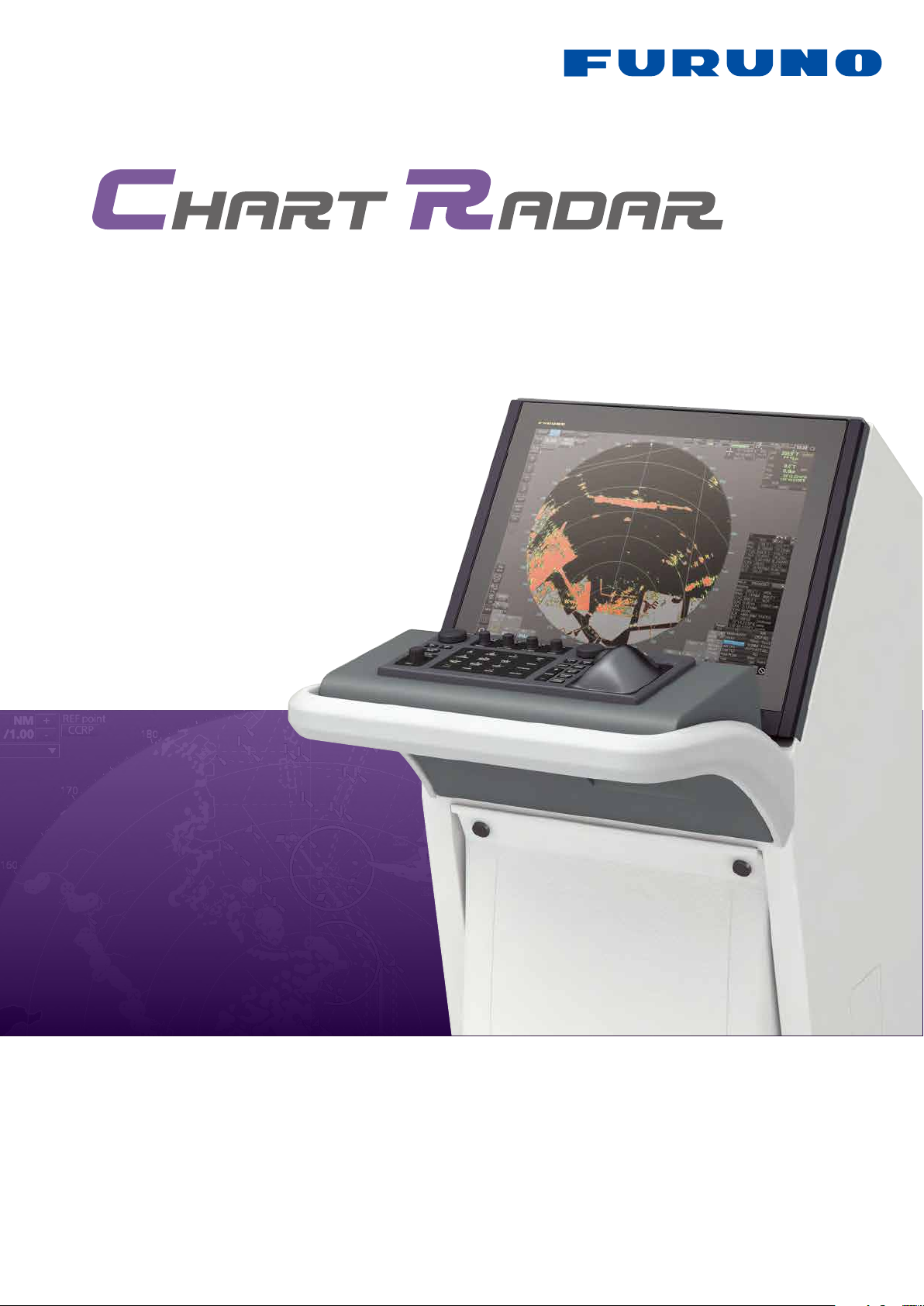
Models:
FAR-3000 series
with an optional pedestal
www.furuno.com
Page 2
FURUNO FAR-3000 Chart Radar offers the reliable situation awareness
and navigation safety by greatly enhanced target detection
FURUNO FAR-3000 Chart Radar offers the reliable situation awareness
and navigation safety by greatly enhanced target detection
Solid State transceiver available
(
for S-band
)
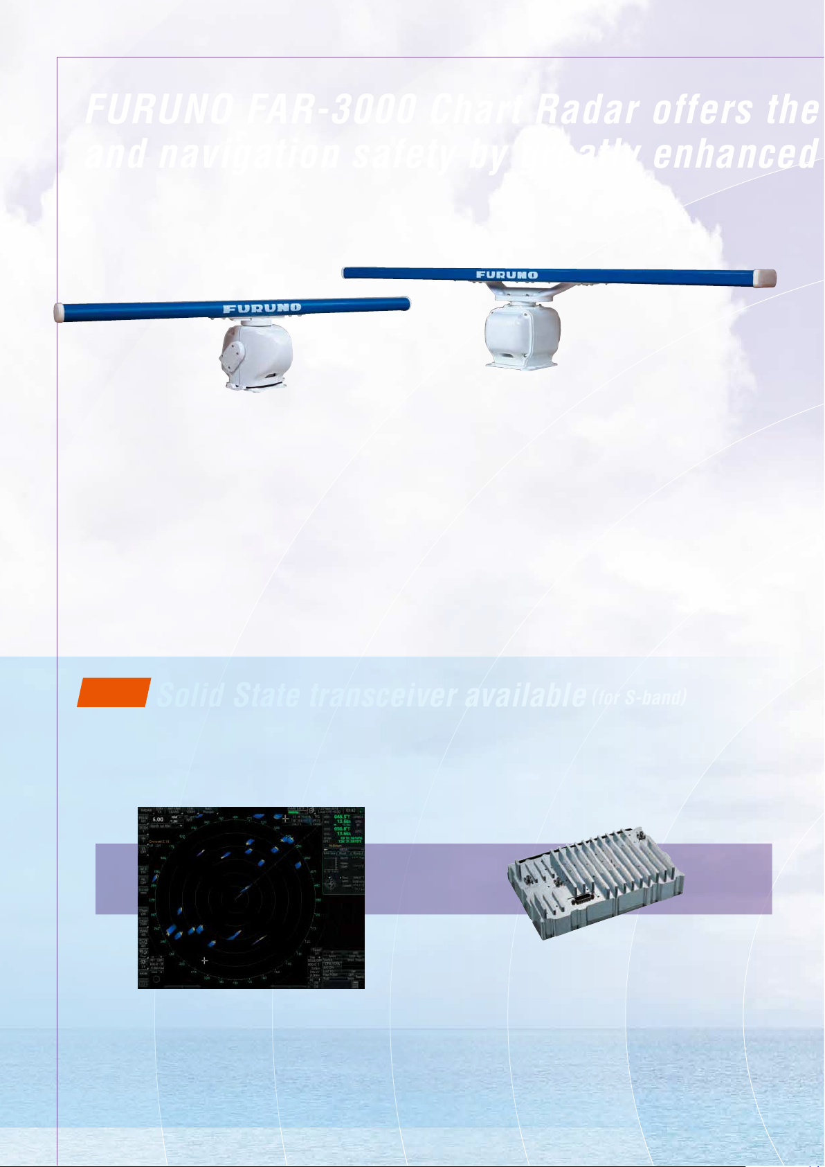
Newly developed antennas with enhanced high durability and reliability
for S-band
for X-band
▲
Newly designed antenna scanners to suppress the aerodynamic drag and prevent a spike in temperature
▲
Less maintenance required through use of the DC brushless motor
▲
Ethernet network link between antenna unit and below deck processor unit
The analog signals are converted into the digital signals within the antenna unit and sent to the below deck
processor unit via Ethernet network. This network technology eliminates loss of signal gain between antenna unit
and processor unit that may be seen in conventional Radar system.
▲
Optional LAN Signal Converter enables users to extend the cable between antenna unit and processor
unit or to utilize the existing cables when retrotting
NEW
▲
Less noise and much clearer targets
FURUNO’s Solid State Radar technology generates clearer echo images,
which allows users to obtain clearer picture of what are around their
vessel, including weak targets from small craft.
Solid State transceiver available
(
for S-band
The newly developed Power Amplier generates properly modulated
radio frequency to the targets around the vessels. Also, the receiver
catches the weak signals, which are processed inside the Power
Amplier module to reduce the clutters.
Power Amplier Module
of the Solid State transceiver
)
Solid State
▲
Fan-less antenna design requires less maintenance
▲
Lower maintenance hours and costs compared to Magnetron radar
No need to replace the Magnetron
Page 3
▲
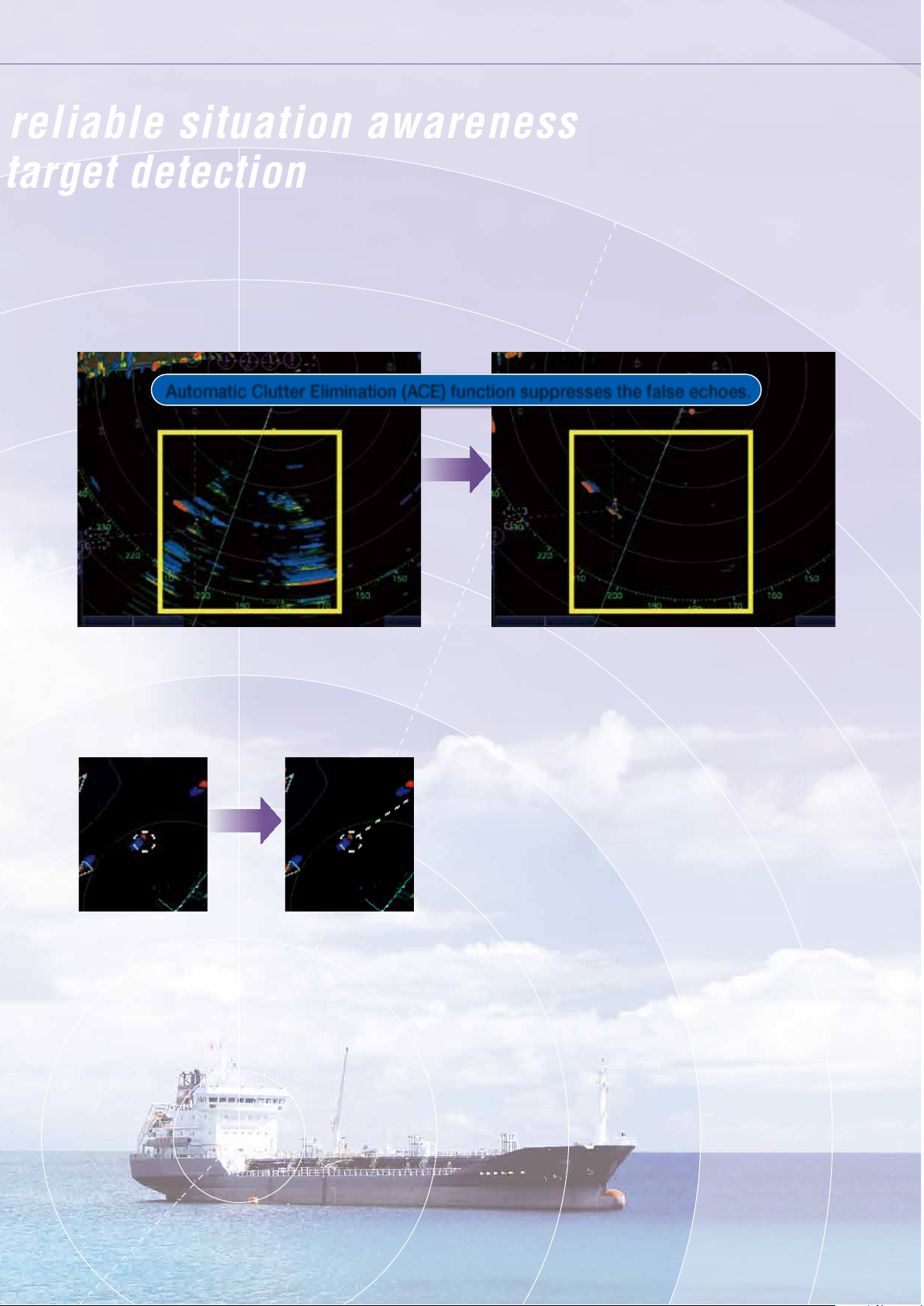
Automatic Clutter Elimination (ACE) function provides clear echoes
Users can quickly adjust the radar image with a single action. When Automatic Clutter Elimination (ACE) function is activated, the system automatically adjusts
the clutter reduction lter and gain control according to the sea and weather conditions selected (Calm/Rough Sea/Hard Rain).
Our advanced echo averaging architecture is also incorporated into Automatic Clutter Elimination (ACE) function. Users can avoid complicated adjustment
processes, resulting in clear echo images.
Automatic Clutter Elimination (ACE) function suppresses the false echoes.
Automatic Clutter Elimination (ACE)
OFF
Automatic Clutter Elimination (ACE)
ON
▲
Improved Target Tracking (TT) function
• Target acquisition takes only a few seconds • Acquired target does not jump to adjacent target
• Reliable and stable tracking of high-speed and
rapidly maneuvering vessels
a few
seconds
▲
Advanced Interference Reduction (IR) function
Target Echo does not become smaller even with IR on
▲
26" Wide LCD monitor compatibility
▲
Complies with the following regulations:
• IEC62388 Ed. 2.0
• IEC61174 Ed. 3.0
• IEC62288
• IEC61162-1 Ed. 4.0
• IEC61162-2
Page 4
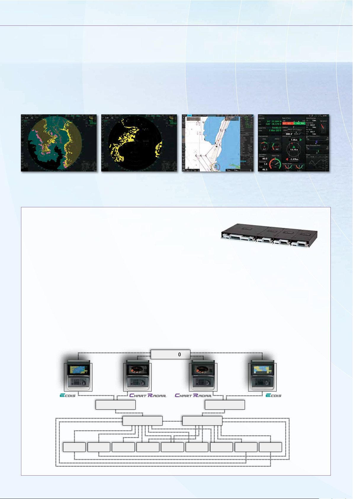
Multifunction display (MFD) capability*
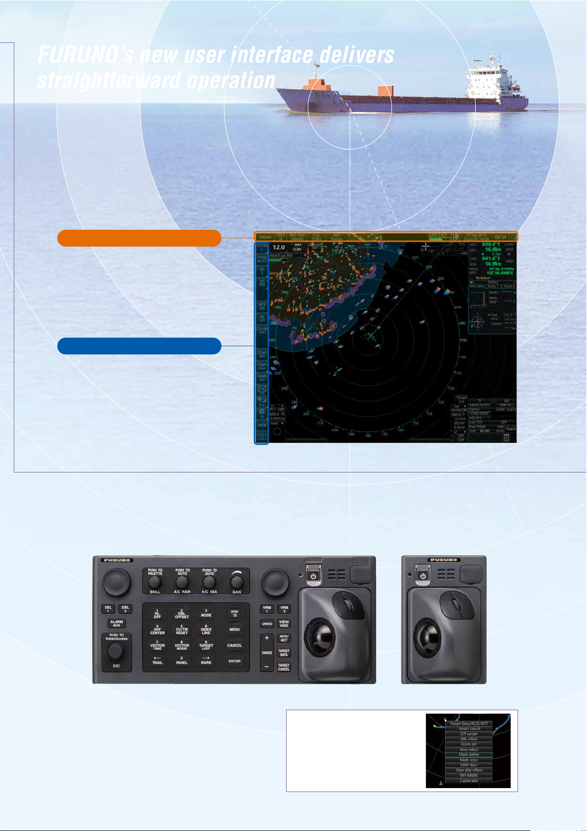
FURUNO’s new user interface delivers
straightforward operation
FURUNO offers workstations that combine exibility and redundancy. Users may easily select ECDIS, Chart Radar,
Conning display or Alert Management System at any multi-function display. Navigators will enjoy reduced workload
and signicant freedom to move about the bridge. All necessary information is available on a variety of displays and
at locations that may be altered as required.
*MFD capability is to be implemented as software update
Radar (Chart ON
)
Radar (Chart OFF
)
ECDIS
Conning Information Display
Sensor Adapter
▲
Common sensor adaptor makes installation and maintenance easy
The Sensor Adapter acts as a central medium to gather all of the sensor data and collectively feed
it to all FAR-3000 Chart Radar and FMD-3200/3300 ECDIS in the network. Since the sensor adapter
can be extended to interface with all the sensors within the network, individual cable connections
in the sensor-to-Chart Radar/ECDIS interface can be greatly reduced.
Navigation sensors can be directly interfaced with the processor’s 8 serial I/0 ports.
Sensor adapters are required under the following conditions:
• The sensor data is to be shared amongst multiple networked Chart Radar and ECDIS systems,
• The number of sensors interfaced is more than the number of the ports the processor has (8 serial I/O ports, 1 digital IN and 6 digital OUT), and/or
• The networked sensors include analog sensors.
In order to integrate onboard sensors into the navigation network, the sensor adapter may be interfaced with the switching
hub HUB-100 from which distribution of the sensor data throughout the network is possible. Alternatively, multiple sensor
adapters may be interfaced via Ethernet to integrate onboard sensors for use in the shipboard network.
System diagram for the new Chart Radar
Model:
FAR-3000
HUB-3000
HUB-100 HUB-100
Sensor AdapterSensor Adapter
Gyro 1 Gyro 2GPS 1 GPS 2HCS Speed log
Anemometer
Nav. E.S. AIS
Page 5
FURUNO’s new user interface delivers
straightforward operation
FURUNO’s new user interface delivers
straightforward operation
Unique & smart operation tool – “Status bar” and “InstantAccess bar”
The user interface of the Radar utilizes carefully organized operational tools: The Status bar and The InstantAccess bar.
These operational tools deliver straightforward, task-based operation by which the operator can quickly perform tasks
without having to navigate an intricate menu tree.
Status bar
Status bar contains information about
the operating status, i.e., MFD operating
mode, main tasks assigned to each
MFD operating mode.
InstantAccess bar
InstantAccess bar contains all the tasks
(functions or actions) corresponding to
the operation mode currently selected
so that quick access to necessary
functions/actions can be made.
Stress-free operation with the well-designed control unit
Intuitive operation
All operations can be controlled with the trackball.
Contextual menu
The context menu contains all the
available actions related to the selected
icon or area, it provides quick access to
tasks.
Page 6
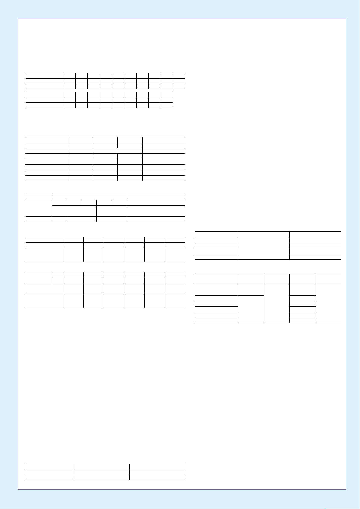
SPECIFICATIONSSPECIFICATIONS
PRODUCT NAME
MARINE RADAR
GENERAL
Range Scales and Ring Intervals
Range scales (NM)
Ring intervals (NM)
Number of Rings
Range scales (NM)
Ring intervals (NM)
Number of Rings
1, 2, 4, 8, 16, 32, 72, 120 NM cannot be selected on IMO radar.
ANTENNA UNIT
Radiator Type
Beamwidth and Sidelobe
Radiator Type
Length
Frequency
Beamwidth (H) (-3 dB)
Beamwidth (H) (-20 dB)
Beamwidth (V)
Sidelobe (within ±10°)
Sidelobe (outside ±10°)
TRANSCEIVER UNIT
Transceiver Unit
Frequency
Output Power
Pulselength, Pulse Repetition Rate (PRR) and Range scale
Magnetron
Pulselength (μs)
PRR (Hz)
Range scale (NM)
0.125
0.025
5
8
2
4
RTR-105 RTR-106 RTR-108 RTR-107 RTR-109
X band: 9410±30 MHz
12 kW 25 kW 30 kW
0.07
3000*
0.125/0.25/
0.5/0.75/1/
1.5/2
0.5
0.25
0.1
0.05
5
5
16
12
4
2
4
6
Slotted waveguide array
XN12CF
4 ft
1.9°
4.5°
20°
-24 dB
-30 dB
Magnetron
XN20CF
X band: 9410±30 MHz
S band: 3050±30 MHz
0.15
3000*
0.5/0.75/
1/1.5/2/3/4
0.75
0.25
3
24
4
6
6.5 ft
1.23°
2.9°
20°
-28 dB
-32 dB
0.75/1/1.5/
2/3/4/6/
1
0.25
4
32
8
4
0.3
1500
8/12
XN24CF
1. 5
0.25
6
48
8
6
8 ft
0.95°
2.4°
20°
-28 dB
-32 dB
①P0N: 3043.75 MHz/Q0N: 3063.75±5 MHz
②P0N: 3053.75 MHz/Q0N: 3073.75±5 MHz
0.5
1200
1.5/2/3/
4/6/8/12/
16/24
0.5
0.5
6
4
96
72
16
12
6
6
SN36CF
S band: 3050±30 MHz
-24 dB
-30 dB
Solid State
RTR-111
250 W
0.7
1000
3/4/6/8/
12/16/24
1
4
120
20
6
12 ft
1.8°
4.5°
25°
1
6
1. 2
600**
6/8/12/16/
24/32/48/
96/120
6
4
3
2
INTERFACE
Processor Unit
DVI
LAN
USB
COM
Serial I/O
Sentences
Input
Output
Digital Input
Contact Closure
Sensor Adapter
Control and Serial Input
LAN
Serial
Analog Input
Digital Input
Digital Output
POWER SUPPLY
Monitor unit
MU-231
MU-190
Processor unit
Power Supply Unit
PSU-014
PSU-015
PSU-016
PSU-018
2 ports, DVI-D (Video signal from DVI-1 and DVI-2 is identical)
1 port, DVI-I Ver. 1.1 (RGB for VDR)
2 ports, Ethernet 1000 Base-T (for Interswitch and Sensor Adapter)
1 port, 100 Base-TX (for Radar sensor)
4 ports, USB 2.0 type-A
2 ports, RS232C/RS-485 (for brilliance control)
8 ports
IEC61162-1/2 (2 ports), IEC61162-1 (6 ports)
ABK, ACK, ACM, ALR, CUR, DBT, DPT, DTM, GGA, GLL, GNS,
HBT, HDT, MTW, MWV, RMC, THS, VBW, VDM, VDO, VDR,
VHW, VTG, ZDA
ABM, ACK, ALC, ALF, ALR, ARC, BBM, EVE, HBT, OSD, RSD,
TLB, TTD, TTM, VSD
1 port (for ACK signal input)
6 ports
1 port for system fail, 1 port for power fail, 2 ports for normal close,
and 2 ports for nomal open
1 port, Ethernet 100 Base-TX
8 ports
IEC 61162-1/2 (4 ports), IEC 61162-1 (4 ports)
3 ports/per unit, -10 to +10 V/0 to 10 V, 4 to 20 mA selectable
8 ports/per unit, normal close or open, selectable
8 ports/per unit, normal close or open, selectable
100-230 VAC; 1.0-0.6 A, 1 phase, 50/60Hz
100-230 VAC; 0.7-0.4 A, 1 phase, 50/60Hz
100/230 VAC, 1 phase, 50/60 Hz
Input CurrentInput Voltage
100-230 VAC
1 phase
50/60 Hz
3.7 A
6.4 A
2.8 A
5.6 A
Solid State
Pulselength (μs)
PRR (Hz)
Range scale (NM)
* 2200 Hz on TT range = 32 NM
** 500 Hz on 96/120 NM range
*** 1800 Hz on TT range = 32 NM
**** 1500 Hz on TT range = 32 NM
PROCESSOR UNIT
Chart Materials
Data Presentation
Own Ship
Target Data
Position Calculation
Navigation Planning
Route Monitoring
User Chart
Notes Data
MOB (Man Overboard)
DISPLAY UNIT
Display Unit
Display Type
Resolution
(TT: ARPA, AIS)
P0N
Q0N
0.07
5.0
2400***
0.125/0.25/
0.5/0.75/1/
1.5/2
0.18
7. 5
2000****
0.5/0.75/
1/1.5/2/3/4
IMO/IHO S57 edition-3 ENC vectorized material
(IHO S-63 ENC data protection scheme),
C-MAP and CM-93/3 vectorized materials
Own ship's mark and numeral position in lat/lon,
speed and course
Range, bearing, speed, course, CPA/TCPA, BCR/BCT
Target information from AIS
Navigation by result from external position sensor
Dead reckoning with gyro and log data from gyro, log,
and position sensors to be fed to mathmatical filter to
generate highly accurate position and speed
Planning by rhumb line, great circle
Off-track display, waypoint arrival alarm, shallow depth alarm
User chart creation and display
Create and display notes data
Position, and other data at time of man overboard are
recorded MOB mark is displayed on the screen
19" color LCD
SXGA(1280×1024 pixels
MU-190
0.3
12.5
1500
0.75/1/1.5/
2/3/4/6/8
0.5
1 7. 5
1060
3/4/6/8/
12/16/24
(waypoint, ship's hull and status)
)
0.7
18.3
600 (96 NM)
1000
450 (120 NM)
6/8/12/16/
3/4/6/8/
12/16/24
23.1" color LCD
UXGA(1600×1200 pixels
24/32/48/
MU-231
1. 2
18.3
96/120
ENVIRONMENTAL CONDITIONS
Unit Ambient
Antenna Unit
Power Supply Unit
Processor Unit
Control Unit
Sensor Adapter
Monitor Unit
Temperature
-25°C to +55°C
(storage +70°C)
-15°C to +55°C
EQUIPMENT LIST
Standard
Display Unit
Processor Unit
Control Unit
Radar Control Unit
Trackball Control Unit
Antenna Radiator
Transceiver
Gear Box
Performance Monitor
Power Supply Unit
Cable between Power Supply Unit and Antenna Unit
LAN Cable between Processor Unit and Power Supply Unit
Standard Spare Parts and Installation Materials
Option
Sensor Adapter
Sub Display Radar Cable
Deicer
Junction Box (for foremast mounting)
Composite Cable between Junction Box and Antenna/
Power Supply Unit (for foremast mounting)
LAN Signal Converter (for foremast mounting)
Switching Hub for sensor network
)
Intelligent Hub for interswitch network
MU-190/231
EC-3000
RCU-025
RCU-026
XN12CF/XN20CF/XN24CF/
SN36CF
RTR-105/106/107/108/109/111
RSB-128/129/130/131/133
PM-32A/52A/52B
PSU-014/015/016/018
Relative
Humidity
93 %
or less at
40°C
Degree of
protection
IP56
IP20
IP20
IP22
IP22
IP22
1 unit (specify when ordering)
MC-3000S/3010A/
3020D/3030D
RW-00136
OP03-226/227
RJB-001
RW-9600
OP03-223
HUB-100
HUB-3000
Vibration
IEC 60945
Ed. 4
1 unit
1 unit
1 unit
1 unit
1 unit
1 unit
1 unit
1 unit
1 pc
1 pc
1 set
Page 7
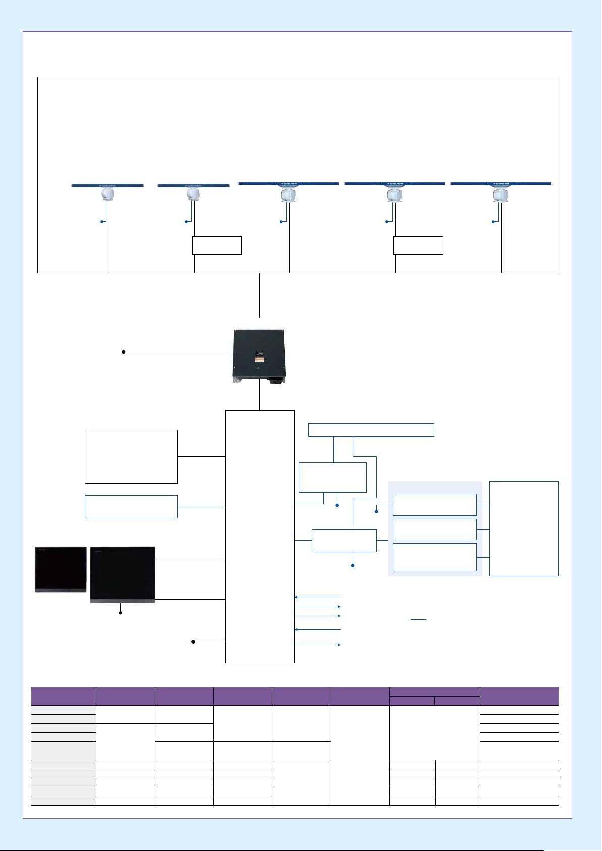
INTERCONNECTION DIAGRAMINTERCONNECTION DIAGRAM
FAR-3210/3310/3220/3320 FAR-3320W FAR-3230S/3330S FAR-3230S-SSD/3330S-SSDFAR-3330SW
Radiator
XN12CF (4 ft)
XN20CF (6.5 ft)
XN24CF (8 ft)
Gear Box
RSB-128
(24/42 rpm)
Performance Monitor
PM-32A
Deicer Kit OP03-226
Radiator
XN20CF (6.5 ft)
XN24CF (8 ft)
Gear Box
RSB-130
(24/42 rpm)
Performance Monitor
PM-32A
Deicer Kit OP03-226
Radiator
SN36CF (12 ft)
Gear Box
RSB-129
(24/42 rpm)
Performance Monitor
PM-52A
Deicer Kit OP03-227
Radiator
Gear Box
Performance Monitor
PM-52A
Deicer Kit OP03-227
SN36CF (12 ft)
RSB-131
(24/42 rpm)
Radiator
SN36CF (12 ft)
Gear Box
RSB-133
(24/42 rpm)
Performance Monitor
PM-52B
Deicer Kit OP03-227
100-115/220-230 VAC
1ø, 50/60 Hz
for Deicer
100-230 VAC
1ø, 50/60 Hz
Monitor Unit
MU-190
19"
100-230 VAC 1ø, 50-60 Hz
Transceiver
RTR-105 (12 kw)
RTR-106 (25 kw)
100-115/220-230 VAC
1ø, 50/60 Hz
for Deicer
Control Unit
RCU-025
or
Trackball Control Unit
RCU-026
USB Keyboard
USB Mouse
DVI cable
MU-231
23.1"
WUXGA monitor: 2 m (max.)
MU-190: 5/10 m (max.)
MU-231: 5 m (max.)
RS-485
MU-190: 10 m (max.)
MU-231: 5 m (max.)
for Brill control
100-115/220-230 VAC
1ø, 50-60 Hz
100-115/220-230 VAC
Transceiver Unit
RTR-108 (25 kW)
1ø, 50/60 Hz
for Deicer
Power Supply Unit
Processor Unit
EC-3000
Transceiver
RTR-107 (30 kW)
100-115/220-230 VAC
1ø, 50/60 Hz
for Deicer
Transceiver Unit
RTR-109 (30 kW)
Note:
1. Length of LAN cable is 50 m (max.)
2. Cable between Sensor Adapter components
should be no longer than 6 m.
FAR-3210/3310/3220/3320/3320W:
FAR-3230S/3330S/3330SW (24 rpm) :
FAR-3230S/3330S/3330SW (42 rpm) :
FAR-3230S-SSD/3330S-SSD (24 rpm):
FAR-3230S-SSD/3330S-SSD (42 rpm):
Processor Unit EC-3000 for ECDIS and Radar*
* Up to 8 EC-3000 Processor Units can be
interfaced through single HUB-3000.
Intelligent Hub
HUB-3000
8 ports
100-230 VAC
1ø, 50/60 Hz
24 VDC
Switching Hub
HUB-100
100-230 VAC
1ø, 50/60 Hz
Navigation Sensors
System Fail
Power Fail
ACK IN
DVI-RGB Cable
VDR
PSU-014
PSU-014
PSU-015
PSU-016
PSU-018
Sensor Adapter
Serial MC-3000S (8 ports)
Analog MC-3010A (3 ports)
MC-3020D/3030D
100-115/220-230 VAC
1ø, 50/60 Hz
for Deicer
Digital IN/OUT
(8 ports each)
Option or connectable equipment
Transceiver
RTR-111 (250 W)
Navigation Sensors
Gyrocompass
AIS
GPS
NAVTEX
Wind Indicator
Echo Sounder
Speed Log
Water Temp. Sensor
etc.
Model Output Power
FAR-3210
FAR-3310
X band 12 kW
FAR-3220
FAR-3320
X band 25 kW
FAR-3320W
FAR-3230S
FAR-3230S-SSD
FAR-3330S
FAR-3330SW
FAR-3330S-SSD
S band 30 kW
S band 250 W
S band 30 kW
S band 30 kW
S band 250 W
Transceiver Unit Radiator Length Rotation
RTR-105
RTR-106
RTR-108
RTR-107
RTR-111
RTR-107
RTR-109
RTR-111
Gear Box
RSB-128
RSB-130
RSB-129
RSB-133
RSB-129
RSB-131
RSB-133
4 ft (XN12CF)
6.5 ft (XN20CF)
8 ft (XN24CF)
6.5 ft (XN20CF)
8 ft (XN24CF)
12 ft (SN36CF)
24/42 rpm
Power Supply Unit
24 rpm 42 rpm
PSU-014
PSU-014
PSU-016
PSU-014
PSU-014
PSU-016
PSU-015
PSU-018
PSU-015
PSU-015
PSU-018
Display Unit
19.0" SXGA (MU-190)
23.1" UXGA (MU-231)
19.0" SXGA (MU-190)
23.1" UXGA (MU-231)
23.1" UXGA (MU-231)
19.0" SXGA (MU-190)
19.0" SXGA (MU-190)
23.1" UXGA (MU-231)
23.1" UXGA (MU-231)
23.1" UXGA (MU-231)
Page 8
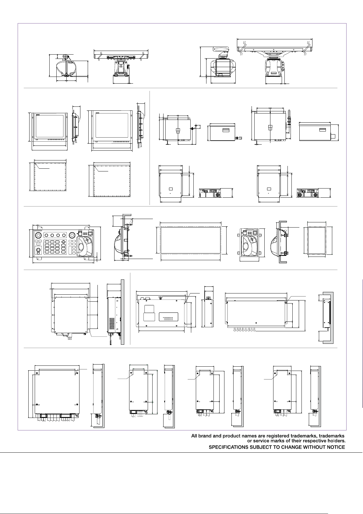
Antenna Unit for FAR-3210/3310/3220/3320/3320W
Radiator
XN12CF 46.2 kg 101.9 lb
XN20CF 48.1 kg 106.1 lb
XN24CF 49.3 kg 108.7 lb
4.3"
109
575 22.7"
255 10.0" 257 10.1"
15
395 15.6"
0.6"
XN12CF: 1297 51.1"
XN20CF: 2097 82.6"
XN24CF: 2597 102.2"
9
409 16.1"
0.35"
Antenna Unit for FAR-3230S/3330S/3330SW/3230S-SSD/3330S-SSD
Radiator SN36CF 144 kg 317.5 lb
769 30.3"
457 18.0"
12
0.5"
640 25.2"
3822 150.5"
420 16.5" 69 2.7"
Monitor Unit
MU-190 8.8 kg 19.4 lb
397 15.6"
450 17.7"
489 19.3"
448 17.6"
4-Ø18
389 15.3"
Cutout for ush mount
Control Unit
RCU-025 3.1 kg 6.84 lb
180 7.09"
339 13.3"32 1.26"
398 15.7"
MU-231 12.8 kg 28.2 lb
110
4.3"
484.9 19"
4-R10
471 18.5"
Cutout for ush mount
216 8.50"
553 21.8"
592 23.3"
554 21.8"
no less than 70 2.76"
55 2.17"
38 1.50"
112
4.4"
72 2.83" max.
10 to 20
0.39" to 0.79"
Transceiver Unit for FAR-3320W
RTR-108 17 kg 37.5 lb
200 7.9"
200 7.9"
37 1.5"
384 15.1"
8 0.3"
12 0.5"
422 16.6"
279.5 11.0"
70
2.8"
70 2.8"
484 19.1"
291 11.5"
Power Supply Unit
PSU-014/016 8.5 kg 18.7 lb
392 15.4"
370 14.6"
350 13.4"
170 6.69"
32
1.3"
340 13.4"
405 15.9"
398 15.7"
388 15.3"
Cutout for ush mount Cutout for ush mount
Transceiver Unit for FAR-3330SW
RTR-109 22 kg 48.5 lb
260 10.2"
15 0.6"
546 21.5"
10 0.4"
PSU-015/018 10 kg 22.0 lb
392 15.4"
370 14.6"
150
5.9"
350 13.4"
Trackball Control Unit
RCU-026 1.5 kg 3.31 lb
180 7.09"
120 4.72"
180 7.09"
260 10.2"
no less than
70 2.76"
606 23.9"
65
2.6"
94
3.7"
32
1.3"
340 13.4"
405 15.9"
Max 70
2.76"
120 4.72"
170 6.69"
110 4.33"
150
313 12.3"
5.9"
180 7.09"
Processor Unit
EC-3000
14 kg 30.9 lb
15 0.59"
426 16.77"
396 15.59"
360 14.17"
Sensor Adapter
Serial : MC-3000S 1.5 kg 3.3 lb
220 8.66"
180 7.09"
150 5.91"64 2.52"
235.5 9.27"
4-ø5
Fixing
Hole
153 6.02"
150 5.9"
45 1.77"150 5.9" 150 5.9"
3-ø8
Fixing hole
48 1.88"
41 1.61"
no less than 150 5.91"
Switching Hub
HUB-100 1.5 kg 3.31 lb
270 10.63"
255 10.03"
242 9.53"
4-ø5
Fixing Hole
162 6.38"
115 4.53"
15 0.59"
47 1.85"
45
1.77"
145 5.71"
Intelligent Hub
HUB-3000
1.5 kg 3.31 lb
350 13.79"
336 12.23"
324 12.76"
4-ø5
Fixing hole
153 6.02"
103 4.06"
33
1.3"
no less than
172 6.77"
no less than
42 1.65"
100 3.94"
150 5.91"
Analog : MC-3010A 0.8 kg 1.8 lb Digital In : MC-3020D 0.8 kg 1.76 lb Digital Out : MC-3030D 0.8 kg 1.76 lb
48 1.88"
41 1.61"
150 5.91"64 2.51"
235.5 9.25"
no less than 150 5.91"
4-ø5
Fixing
Hole
100 3.94"
60 2.36"
48 1.88"
41 1.61"
150 5.91"64 2.52"
235.5 9.25"
no less than 150 5.91"
4-ø5
Fixing
Hole
100 3.94"
60 2.36"
150 5.91"64 2.52"
235.5 9.25"
48 1.88"
41 1.61"
no less than 150 5.91"
4-ø5
Fixing
Hole
100 3.94"
60 2.36"
FURUNO ELECTRIC CO., LTD.
Nishinomiya, Hyogo, Japan
www.furuno.com
FURUNO U.S.A., INC.
Camas, Washington, U.S.A.
www.furunousa.com
FURUNO (UK) LIMITED
Havant, Hampshire, U.K.
www.furuno.co.uk
FURUNO NORGE A/S
Ålesund, Norway
www.furuno.no
FURUNO DANMARK A/S
Hvidovre, Denmark
www.furuno.dk
FURUNO SVERIGE AB
Västra Frölunda, Sweden
www.furuno.se
FURUNO FINLAND OY
Espoo, Finland
www.furuno.
FURUNO POLSKA Sp. Z o.o.
Gdynia, Poland
www.furuno.pl
FURUNO DEUTSCHLAND GmbH
Rellingen, Germany
www.furuno.de
FURUNO FRANCE S.A.S.
Bordeaux-Mérignac, France
www.furuno.fr
FURUNO ESPAÑA S.A.
Madrid, Spain
www.furuno.es
FURUNO ITALIA S.r.l.
Genoa, Italy
FURUNO HELLAS S.A.
Glyfada, Greece
www.furuno.gr
FURUNO (CYPRUS) LTD
Limassol, Cyprus
www.furuno.com.cy
FURUNO EURUS LLC
St. Petersburg, Russian Federation
www.furuno.com.ru
FURUNO SHANGHAI CO., LTD.
Shanghai, China
www.furuno.com/cn
FURUNO KOREA CO., LTD.
Busan, Korea
RICO (PTE) LTD
Singapore
www.rico.com.sg
14075SK Printed in Japan
Catalogue No. R-204b
 Loading...